US5862968A - Separator for linerless labels - Google Patents
Separator for linerless labels Download PDFInfo
- Publication number
- US5862968A US5862968A US08/736,089 US73608996A US5862968A US 5862968 A US5862968 A US 5862968A US 73608996 A US73608996 A US 73608996A US 5862968 A US5862968 A US 5862968A
- Authority
- US
- United States
- Prior art keywords
- web
- rolls
- infeed
- outfeed
- pair
- Prior art date
- Legal status (The legal status is an assumption and is not a legal conclusion. Google has not performed a legal analysis and makes no representation as to the accuracy of the status listed.)
- Expired - Fee Related
Links
Images


Classifications
-
- B—PERFORMING OPERATIONS; TRANSPORTING
- B65—CONVEYING; PACKING; STORING; HANDLING THIN OR FILAMENTARY MATERIAL
- B65C—LABELLING OR TAGGING MACHINES, APPARATUS, OR PROCESSES
- B65C9/00—Details of labelling machines or apparatus
- B65C9/08—Label feeding
- B65C9/18—Label feeding from strips, e.g. from rolls
- B65C9/1896—Label feeding from strips, e.g. from rolls the labels being torn or burst from a strip
-
- B—PERFORMING OPERATIONS; TRANSPORTING
- B26—HAND CUTTING TOOLS; CUTTING; SEVERING
- B26D—CUTTING; DETAILS COMMON TO MACHINES FOR PERFORATING, PUNCHING, CUTTING-OUT, STAMPING-OUT OR SEVERING
- B26D5/00—Arrangements for operating and controlling machines or devices for cutting, cutting-out, stamping-out, punching, perforating, or severing by means other than cutting
- B26D5/20—Arrangements for operating and controlling machines or devices for cutting, cutting-out, stamping-out, punching, perforating, or severing by means other than cutting with interrelated action between the cutting member and work feed
- B26D5/30—Arrangements for operating and controlling machines or devices for cutting, cutting-out, stamping-out, punching, perforating, or severing by means other than cutting with interrelated action between the cutting member and work feed having the cutting member controlled by scanning a record carrier
- B26D5/32—Arrangements for operating and controlling machines or devices for cutting, cutting-out, stamping-out, punching, perforating, or severing by means other than cutting with interrelated action between the cutting member and work feed having the cutting member controlled by scanning a record carrier with the record carrier formed by the work itself
-
- B—PERFORMING OPERATIONS; TRANSPORTING
- B65—CONVEYING; PACKING; STORING; HANDLING THIN OR FILAMENTARY MATERIAL
- B65C—LABELLING OR TAGGING MACHINES, APPARATUS, OR PROCESSES
- B65C9/00—Details of labelling machines or apparatus
- B65C9/08—Label feeding
- B65C9/18—Label feeding from strips, e.g. from rolls
- B65C9/1803—Label feeding from strips, e.g. from rolls the labels being cut from a strip
-
- B—PERFORMING OPERATIONS; TRANSPORTING
- B65—CONVEYING; PACKING; STORING; HANDLING THIN OR FILAMENTARY MATERIAL
- B65C—LABELLING OR TAGGING MACHINES, APPARATUS, OR PROCESSES
- B65C9/00—Details of labelling machines or apparatus
- B65C9/40—Controls; Safety devices
- B65C9/42—Label feed control
- B65C9/44—Label feed control by special means responsive to marks on labels or articles
-
- B—PERFORMING OPERATIONS; TRANSPORTING
- B65—CONVEYING; PACKING; STORING; HANDLING THIN OR FILAMENTARY MATERIAL
- B65H—HANDLING THIN OR FILAMENTARY MATERIAL, e.g. SHEETS, WEBS, CABLES
- B65H35/00—Delivering articles from cutting or line-perforating machines; Article or web delivery apparatus incorporating cutting or line-perforating devices, e.g. adhesive tape dispensers
- B65H35/04—Delivering articles from cutting or line-perforating machines; Article or web delivery apparatus incorporating cutting or line-perforating devices, e.g. adhesive tape dispensers from or with transverse cutters or perforators
- B65H35/08—Delivering articles from cutting or line-perforating machines; Article or web delivery apparatus incorporating cutting or line-perforating devices, e.g. adhesive tape dispensers from or with transverse cutters or perforators from or with revolving, e.g. cylinder, cutters or perforators
-
- B—PERFORMING OPERATIONS; TRANSPORTING
- B65—CONVEYING; PACKING; STORING; HANDLING THIN OR FILAMENTARY MATERIAL
- B65H—HANDLING THIN OR FILAMENTARY MATERIAL, e.g. SHEETS, WEBS, CABLES
- B65H35/00—Delivering articles from cutting or line-perforating machines; Article or web delivery apparatus incorporating cutting or line-perforating devices, e.g. adhesive tape dispensers
- B65H35/10—Delivering articles from cutting or line-perforating machines; Article or web delivery apparatus incorporating cutting or line-perforating devices, e.g. adhesive tape dispensers from or with devices for breaking partially-cut or perforated webs, e.g. bursters
-
- G—PHYSICS
- G07—CHECKING-DEVICES
- G07F—COIN-FREED OR LIKE APPARATUS
- G07F11/00—Coin-freed apparatus for dispensing, or the like, discrete articles
- G07F11/68—Coin-freed apparatus for dispensing, or the like, discrete articles in which the articles are torn or severed from strips or sheets
-
- B—PERFORMING OPERATIONS; TRANSPORTING
- B65—CONVEYING; PACKING; STORING; HANDLING THIN OR FILAMENTARY MATERIAL
- B65C—LABELLING OR TAGGING MACHINES, APPARATUS, OR PROCESSES
- B65C9/00—Details of labelling machines or apparatus
- B65C9/08—Label feeding
- B65C9/18—Label feeding from strips, e.g. from rolls
- B65C9/1803—Label feeding from strips, e.g. from rolls the labels being cut from a strip
- B65C2009/1834—Details of cutting means
- B65C2009/1857—Details of cutting means two co-acting knifes
- B65C2009/1861—Details of cutting means two co-acting knifes whereby one knife remains stationary
-
- B—PERFORMING OPERATIONS; TRANSPORTING
- B65—CONVEYING; PACKING; STORING; HANDLING THIN OR FILAMENTARY MATERIAL
- B65H—HANDLING THIN OR FILAMENTARY MATERIAL, e.g. SHEETS, WEBS, CABLES
- B65H2511/00—Dimensions; Position; Numbers; Identification; Occurrences
- B65H2511/50—Occurence
- B65H2511/51—Presence
- B65H2511/512—Marks, e.g. invisible to the human eye; Patterns
-
- Y—GENERAL TAGGING OF NEW TECHNOLOGICAL DEVELOPMENTS; GENERAL TAGGING OF CROSS-SECTIONAL TECHNOLOGIES SPANNING OVER SEVERAL SECTIONS OF THE IPC; TECHNICAL SUBJECTS COVERED BY FORMER USPC CROSS-REFERENCE ART COLLECTIONS [XRACs] AND DIGESTS
- Y10—TECHNICAL SUBJECTS COVERED BY FORMER USPC
- Y10T—TECHNICAL SUBJECTS COVERED BY FORMER US CLASSIFICATION
- Y10T225/00—Severing by tearing or breaking
- Y10T225/10—Methods
- Y10T225/16—Transversely of continuously fed work
-
- Y—GENERAL TAGGING OF NEW TECHNOLOGICAL DEVELOPMENTS; GENERAL TAGGING OF CROSS-SECTIONAL TECHNOLOGIES SPANNING OVER SEVERAL SECTIONS OF THE IPC; TECHNICAL SUBJECTS COVERED BY FORMER USPC CROSS-REFERENCE ART COLLECTIONS [XRACs] AND DIGESTS
- Y10—TECHNICAL SUBJECTS COVERED BY FORMER USPC
- Y10T—TECHNICAL SUBJECTS COVERED BY FORMER US CLASSIFICATION
- Y10T225/00—Severing by tearing or breaking
- Y10T225/30—Breaking or tearing apparatus
- Y10T225/35—Work-parting pullers [bursters]
-
- Y—GENERAL TAGGING OF NEW TECHNOLOGICAL DEVELOPMENTS; GENERAL TAGGING OF CROSS-SECTIONAL TECHNOLOGIES SPANNING OVER SEVERAL SECTIONS OF THE IPC; TECHNICAL SUBJECTS COVERED BY FORMER USPC CROSS-REFERENCE ART COLLECTIONS [XRACs] AND DIGESTS
- Y10—TECHNICAL SUBJECTS COVERED BY FORMER USPC
- Y10T—TECHNICAL SUBJECTS COVERED BY FORMER US CLASSIFICATION
- Y10T83/00—Cutting
- Y10T83/202—With product handling means
- Y10T83/2092—Means to move, guide, or permit free fall or flight of product
- Y10T83/2094—Means to move product at speed different from work speed
-
- Y—GENERAL TAGGING OF NEW TECHNOLOGICAL DEVELOPMENTS; GENERAL TAGGING OF CROSS-SECTIONAL TECHNOLOGIES SPANNING OVER SEVERAL SECTIONS OF THE IPC; TECHNICAL SUBJECTS COVERED BY FORMER USPC CROSS-REFERENCE ART COLLECTIONS [XRACs] AND DIGESTS
- Y10—TECHNICAL SUBJECTS COVERED BY FORMER USPC
- Y10T—TECHNICAL SUBJECTS COVERED BY FORMER US CLASSIFICATION
- Y10T83/00—Cutting
- Y10T83/242—With means to clean work or tool
-
- Y—GENERAL TAGGING OF NEW TECHNOLOGICAL DEVELOPMENTS; GENERAL TAGGING OF CROSS-SECTIONAL TECHNOLOGIES SPANNING OVER SEVERAL SECTIONS OF THE IPC; TECHNICAL SUBJECTS COVERED BY FORMER USPC CROSS-REFERENCE ART COLLECTIONS [XRACs] AND DIGESTS
- Y10—TECHNICAL SUBJECTS COVERED BY FORMER USPC
- Y10T—TECHNICAL SUBJECTS COVERED BY FORMER US CLASSIFICATION
- Y10T83/00—Cutting
- Y10T83/465—Cutting motion of tool has component in direction of moving work
- Y10T83/4766—Orbital motion of cutting blade
- Y10T83/4795—Rotary tool
- Y10T83/4821—Side cutting helical blade
-
- Y—GENERAL TAGGING OF NEW TECHNOLOGICAL DEVELOPMENTS; GENERAL TAGGING OF CROSS-SECTIONAL TECHNOLOGIES SPANNING OVER SEVERAL SECTIONS OF THE IPC; TECHNICAL SUBJECTS COVERED BY FORMER USPC CROSS-REFERENCE ART COLLECTIONS [XRACs] AND DIGESTS
- Y10—TECHNICAL SUBJECTS COVERED BY FORMER USPC
- Y10T—TECHNICAL SUBJECTS COVERED BY FORMER US CLASSIFICATION
- Y10T83/00—Cutting
- Y10T83/525—Operation controlled by detector means responsive to work
- Y10T83/541—Actuation of tool controlled in response to work-sensing means
- Y10T83/543—Sensing means responsive to work indicium or irregularity
-
- Y—GENERAL TAGGING OF NEW TECHNOLOGICAL DEVELOPMENTS; GENERAL TAGGING OF CROSS-SECTIONAL TECHNOLOGIES SPANNING OVER SEVERAL SECTIONS OF THE IPC; TECHNICAL SUBJECTS COVERED BY FORMER USPC CROSS-REFERENCE ART COLLECTIONS [XRACs] AND DIGESTS
- Y10—TECHNICAL SUBJECTS COVERED BY FORMER USPC
- Y10T—TECHNICAL SUBJECTS COVERED BY FORMER US CLASSIFICATION
- Y10T83/00—Cutting
- Y10T83/929—Tool or tool with support
- Y10T83/9372—Rotatable type
- Y10T83/9394—Helical tool
Definitions
- the present invention relates to a handling system for linerless labels and particularly relates to a cutting or bursting system for separating linerless labels with exposed adhesive on one side from a web thereof.
- a separation device for processing linerless labels from a web typically emanating from a roll of linerless label material, the web having adhesive exposed along one side and a slick surface along the opposite side.
- the mechanism of the present invention forms the label from the web by a cutting or bursting operation. In either mode, the cut or burst position is controlled by a preprinted timing mark on the label web. For example, when cutting, the timing mark on the web controls the cut line position. When bursting successive labels from the web, the timing mark is used to initiate the bursting mechanism.
- the web of labels is preprinted with a timing mark and, in the case of bursting, is additionally preperforated in synchronization with the timing mark. Note that marginal punchings are not used with the label stock or with the separation mechanism to advance the web through the mechanism.
- the separating mechanism hereof includes a pair of infeed rolls which are maintained in pressure contact with the label web passing through the nip of the rolls.
- the upper roll is a high friction elastomer or grit roll for positively contacting the slick surface of the label web, while the lower roll has either a silicone elastomer-covered or non-stick plasma-covered surface which is non-cohesive with the adhesive side of the label web.
- the infeed rolls are driven by a first motor responsive to a controller which, upon reading the timing mark, stops the infeed rolls in position for the cutting operation.
- a pair of outfeed rolls, disposed downstream from the infeed rolls, are operated by a second motor independently of the first motor driving the infeed rolls.
- a cutting mechanism comprised of a cylinder mounting a transversely extending blade, preferably in a slight helix orientation relative to the axis of the cylinder, and mounted on one side of the web preferably in opposition to the slick upper side of the web.
- a fixed cutting blade lies preferably on the opposite side of and below the web.
- the cylinder-mounted cutting blade may rotate a full 360° to cut the web or may be oscillated between successive cuts through the web. In either case, the web is cut from one side edge to the other because of the helix configuration of the movable blade.
- a wicking roll is provided to oil the movable blade and prevent the build-up of adhesive along the blades.
- the infeed and outfeed rolls are driven in synchronism and the movable cutting blade rotates in position to effect the cut through the web from one side edge to the opposite side edge.
- the infeed and outfeed rolls are stopped in a position locating the web for a transverse cut at a predetermined longitudinal location along the web in alignment with the fixed blade.
- the infeed rolls are backed or reversed to a slight degree to break the fugitive adhesive bond of the web from the fixed blade of the cut-off mechanism, while the outfeed roll pair are advanced forwardly to discharge the cut label.
- both infeed and outfeed rolls may be stopped after the cut to hold the cut label in cut position and then the outfeed rolls can be programmed to rotate at a second rotational speed, effecting a clean transfer of the severed label to a receiving device and without the need for cooperation with the infeed pair of rolls.
- the cut cylinder may rotate 360°, an alternative form of the invention provides for the cut cylinder to oscillate between a home position and a cut position.
- a smooth breaker bar is used in conjunction with the perforated web.
- the outfeed rolls can be accelerated upon sensing the timing mark to effect separation of the labels along the perforations against the breaker bar.
- a separator having a pair of infeed rolls with a nip therebetween, a pair of outfeed rolls with a nip therebetween and a separating member between the pairs of rolls, a method of separating linerless labels disposed in a web wherein the web has a first surface that will not readily adhere to adhesive on a second surface thereof, comprising the steps of (a) advancing a leading portion of the web through the nips of the infeed and outfeed pairs of rolls in a first direction and past the separating member between the pairs of rolls with the second surface facing away from the separating member as the web moves in the first direction, (b) sensing timing marks on the web and (c) sequentially separating the web into linerless labels by moving the separating member to engage the web in response to periodically sensing the timing marks.
- apparatus for detaching linerless labels from a web having a slippery surface coating on one side and an adhesive coating exposed along its opposite side comprising a pair of infeed rolls rotatable about parallel axes and forming a nip therebetween, with at least one roll thereof having a high friction surface for engaging the slippery coated side of the web and another roll thereof having a substantially non-stick surface for contact with the adhesive coating of the web, a pair of outfeed rolls rotatable about axes parallel to one another and to the axes of the infeed rolls with at least one roll thereof having a substantially non-stick surface for contact with the adhesive coating, a separation device between the pairs of infeed and outfeed rolls for separating the web into linerless labels, a sensor for sensing a mark on the web and providing an output signal in response thereto and means responsive to the output signal for actuating the separation device for forming the linerless labels.
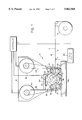
- FIG. 1 is a schematic side elevational view of a separator according to the present invention
- FIG. 2 is a schematic end elevational view of the infeed rolls
- FIG. 3 is an end elevational view illustrating the cutting mechanism on a cut roller
- FIGS. 4 and 5 are illustrative of the helically oriented cutting blade at the beginning and end of the cut, respectively;
- FIG. 6 is a schematic illustration of the infeed rolls backing up to break the fugitive adhesive bond between the cut label and the web;
- FIG. 7 is a schematic illustration of a separator hereof in a bursting mode.
- a separator for forming discrete linerless labels from a web W of label material.
- the separator may be employed in a cutting mode or in a bursting mode.
- the web of labels is provided with preprinted timing marks T along one side for purposes of controlling the cutting or bursting position of the web, as will become apparent from the ensuing description.
- the timing marks are used to initiate the separating mechanism.
- the web W of labels In the bursting mode, the web W of labels has transversely extending lines of perforation which are severed on bursting to form discrete linerless labels.
- the web W is preferably taken from a roll R of web material.
- the web has an exposed adhesive surface A along its underside and a slippery surfaces, i.e., a silicone-coated surface, along its upper side.
- the slippery surface does not readily adhere to the adhesive surface when the web is in roll form. As indicated previously, marginal punching is not used with the label stock.
- the separator mechanism 10 includes a pair of input rolls 12 and 14 defining a nip through which the web W is passed.
- the rolls are mounted for rotation between a pair of opposed frames 16, only one being illustrated in FIG. 1, and are maintained in pressure contact with web W by means of a garter spring 18.
- Spring 18 extends about the end axles 20 and 22 of the rolls 12 and 14, respectively, and a dead post 24.
- the dead post 24 retains the spring on the assembly while facilitating removal of either roll 12 or 14 for jam clearance or cleaning.
- a motor M1 is mounted on a side frame 16 and includes a pulley or belt 26 for connection with the rollers 12 and 14 for driving the rollers in forward and reverse directions as described below.
- the upper roll 12 preferably has high friction elastomer or grit roll surface for effecting positive contact with the slick silicone-coated side of the web W.
- the lower roll 14 has either a silicone elastomer or a non-stick plasma surface, both of which effect little or no cohesion with the adhesive A along the underside of the label web W. It will be appreciated that the orientation of the web and infeed rolls can be reversed with the adhesive on top of the web in contact with the roll 14 and the slick surface on the bottom of the web in contact with the roll 12.
- a pair of outfeed rolls 30 and 32 are similarly positioned downstream from the infeed rolls 12 and 14 and define a nip between which the cut labels are advanced for dispensing from the separator 10.
- the rolls 30 and 32 are mounted similarly as the infeed rolls, employing a garter spring 34.
- the outfeed rolls 30 and 32 are driven by a separate motor M2 through a pulley arrangement 36.
- the rolls 30 and 32 are of substantially identical construction with the rolls 12 and 14, respectively, of the infeed rolls.
- a cylinder assembly 37 on which is mounted a fixed blade 40 in opposition to a cylinder 38 carrying a blade 42 movable with the cylinder 38.
- the blade 40 serves as a fixed anvil in opposition to the movable blade 42, the fixed and movable blades 40 and 42 extending along the underside and upper sides of the web W, respectively.
- Cylinder 38 is mounted for rotation about an axis in the opposite supporting walls 16 and is driven by a separate motor M3. As illustrated in FIG. 3, movable blade 42 forms a helix angle with the axis of rotation of cylinder 38.
- the cylinder 38 is mounted for complete 360° rotation which facilitates the oiling of the blade by a wicking cylinder 50.
- the wicking cylinder includes a felt roll assembly 52 having an outside diameter which slightly interferes with the periphery of the rotary blade 42 as it sweeps past the felt roll 52.
- the felt roll 52 is supported on ball bearings, not shown and is not driven. Oiling is accomplished by a series of oil drip positions comprising passages 53 through a top bar 54.
- the cylinder 38 may be mounted for oscillatory motion about its axis. Oscillatory motion is preferred for improved cycle times where label lengths are relatively short.
- an optical reader 60 for sensing the timing marks T as they pass a predetermined position.
- An output signal from the optical reader 60 responsive to sensing a timing mark, is input to a controller C which, in turn, controls the operation of motors M1, M2 and M3.
- the roll pairs are driven in synchronism by motors M1 and M2, respectively.
- the controller stops the motors M1 and M2 so that the cut cycle may proceed.
- the motor M3 rotating the cut cylinder 38 through 360° or oscillating the movable blade 42, the blade 42 cooperates with the fixed blade 40 to sever the web W at a location providing a predetermined length of cut label.
- the motor M1 is reversed by the controller C.
- the infeed rolls 12 and 14 This reverses or backs up the infeed rollers 12 and 14 to break the fugitive bond of the advancing web W from the fixed blade 40, while the outfeed rolls are again advanced by operation of motor M2 to discharge the cut label from the separator 10.
- the motor M1 reverses direction to rotate the infeed rolls in a direction to advance the web W through the cutting assembly and the outfeed rolls.
- the outfeed rolls may be driven at one rotational speed for infeeding, matching the speed of the infeed rolls, braked to then hold the cut label in its cut position and rotated at a second rotational speed following cut-off to effect clean transfer of the severed label to a receiving means, not shown, and without the need to cooperate with the infeed rolls 12 and 14.
- the infeed and outfeed rolls can be advanced essentially on demand for predetermined intervals as desired.
- a breaker bar 80 is substituted for the rotatable blade.
- the fixed blade 40 may remain in place or be replaced with a smooth edged arbor, not shown against which the advancing web would impinge, while the rotary breaker bar processes to effect separation.
- the web is manufactured with transversely extending perforations such that the discrete labels are formed by breaking the perforations separating the label from the web.
- the bursting operation the movement of the web need not be stopped when forming each discrete label. That is, the bursting operation may be continuous. Additionally, the bursting operation may use the controller to speed up the outfeed rolls once the timing mark has been sensed to effect bursting of the label from the web along the line of perforations.
Abstract
Description
Claims (8)
Priority Applications (1)
| Application Number | Priority Date | Filing Date | Title |
|---|---|---|---|
| US08/736,089 US5862968A (en) | 1995-10-31 | 1996-10-24 | Separator for linerless labels |
Applications Claiming Priority (2)
| Application Number | Priority Date | Filing Date | Title |
|---|---|---|---|
| US08/550,622 US5853117A (en) | 1995-10-31 | 1995-10-31 | Separator for linerless labels |
| US08/736,089 US5862968A (en) | 1995-10-31 | 1996-10-24 | Separator for linerless labels |
Related Parent Applications (1)
| Application Number | Title | Priority Date | Filing Date |
|---|---|---|---|
| US08/550,622 Division US5853117A (en) | 1995-10-31 | 1995-10-31 | Separator for linerless labels |
Publications (1)
| Publication Number | Publication Date |
|---|---|
| US5862968A true US5862968A (en) | 1999-01-26 |
Family
ID=24197932
Family Applications (2)
| Application Number | Title | Priority Date | Filing Date |
|---|---|---|---|
| US08/550,622 Expired - Fee Related US5853117A (en) | 1995-10-31 | 1995-10-31 | Separator for linerless labels |
| US08/736,089 Expired - Fee Related US5862968A (en) | 1995-10-31 | 1996-10-24 | Separator for linerless labels |
Family Applications Before (1)
| Application Number | Title | Priority Date | Filing Date |
|---|---|---|---|
| US08/550,622 Expired - Fee Related US5853117A (en) | 1995-10-31 | 1995-10-31 | Separator for linerless labels |
Country Status (12)
| Country | Link |
|---|---|
| US (2) | US5853117A (en) |
| EP (1) | EP0858422B1 (en) |
| JP (1) | JPH11514618A (en) |
| CN (1) | CN1075031C (en) |
| AU (1) | AU708026B2 (en) |
| BR (1) | BR9611413A (en) |
| CA (1) | CA2235582A1 (en) |
| DE (1) | DE69612392T2 (en) |
| MX (1) | MX9803415A (en) |
| NZ (1) | NZ321813A (en) |
| PT (1) | PT858422E (en) |
| WO (1) | WO1997016369A1 (en) |
Cited By (17)
| Publication number | Priority date | Publication date | Assignee | Title |
|---|---|---|---|---|
| FR2792301A1 (en) * | 1999-04-19 | 2000-10-20 | Protection Decoration Conditio | Handling of labels or sleeves for labelling and presentation of bottles |
| US6173597B1 (en) * | 1996-03-26 | 2001-01-16 | Robert Bosch Gmbh | Tubular plate |
| EP1106514A1 (en) * | 1999-12-03 | 2001-06-13 | Irplastnastri Industria Nastri Adesivi S.p.A. | Machine and process for cutting easy-open seals from an adhesive tape |
| US20010034263A1 (en) * | 1998-04-14 | 2001-10-25 | Roberts Brian J. | Gaming system and method |
| US20030056902A1 (en) * | 1999-03-25 | 2003-03-27 | Alan Constantine | Labeling apparatus |
| US20030085249A1 (en) * | 2001-04-06 | 2003-05-08 | Zih Corp., A Delware Corporation | Carrier-less patch protection including cassette and separation device |
| US20030233168A1 (en) * | 1998-08-03 | 2003-12-18 | Interlott Technologies, Inc. | Item vending machine and method |
| WO2004002695A1 (en) * | 2002-06-28 | 2004-01-08 | Interlott Technologies, Inc. | Ticket dispensing apparatus and method |
| US6932258B1 (en) * | 1998-04-14 | 2005-08-23 | Gtech Corporation | Gaming device and method |
| US20060035698A1 (en) * | 1998-04-14 | 2006-02-16 | Roberts Brian J | Gaming device and method |
| US20060071046A1 (en) * | 1998-04-14 | 2006-04-06 | Roberts Brian J | Ticket dispensing modules and method |
| US20060081674A1 (en) * | 1998-04-14 | 2006-04-20 | Roberts Brian J | Ticket dispensing device, installation and displays |
| US20070241160A1 (en) * | 2006-04-12 | 2007-10-18 | Kenney James W | Automated dispenser |
| EP1862391A1 (en) * | 2006-06-02 | 2007-12-05 | Impaxx Machine Systems, Inc. | Device and method for applying pressure-sensitive adhesive linerless labels to articles |
| US20140053514A1 (en) * | 2012-08-21 | 2014-02-27 | Larry C. Gess | Method and apparatus for changing a strip of sealed bag precursors in to open bags |
| US9139317B2 (en) | 2012-08-21 | 2015-09-22 | Intertape Polymer Corp. | Method and apparatus for opening bags while maintaining a continuous strip of bag precursors |
| US9902079B2 (en) | 2015-01-09 | 2018-02-27 | Boe Technology Group Co., Ltd. | Cutting apparatus for tape |
Families Citing this family (34)
| Publication number | Priority date | Publication date | Assignee | Title |
|---|---|---|---|---|
| US6886728B2 (en) * | 1993-09-30 | 2005-05-03 | Gtech Corporation | Ticket dispensing modules and method |
| US6609644B1 (en) * | 1997-09-26 | 2003-08-26 | Instant Technologies, Inc. | Method of dispensing perforated tickets |
| DE19983972T1 (en) * | 1998-12-14 | 2003-04-17 | Sanjiu Medical & Pharmaceutica | Method and arrangement comprising an electronic control for mixing Chinese herbal medicine |
| DE19958274B4 (en) * | 1999-12-03 | 2006-11-23 | Hengstler Gmbh | Cutter for adhesive labels |
| JP4815059B2 (en) * | 2001-02-28 | 2011-11-16 | 株式会社サトー | Label transport device |
| GB2379918B (en) * | 2001-09-21 | 2004-12-08 | Sovereign Labelling Sys Ltd | Labelling machine |
| DE10208446C1 (en) * | 2002-02-27 | 2003-08-14 | Innotech Innovative Technik | Adhesive tape applicator has additional driven roller between feed roller and pressure roller cooperating with curring blade for separation of adhesive tape |
| US7021214B2 (en) * | 2003-01-27 | 2006-04-04 | Ricoh Company, Ltd. | Method for issuing label with thermosensitive adhesive |
| US7293592B1 (en) | 2003-03-03 | 2007-11-13 | George Schmitt & Co., Inc | Forming and applying linerless labels |
| US6910820B2 (en) * | 2003-07-25 | 2005-06-28 | 3M Innovative Properties Company | Apparatus and method for handling linerless label tape |
| DE102004024340A1 (en) | 2004-05-17 | 2005-12-15 | Mettler-Toledo (Albstadt) Gmbh | Method and device for printing on a surface of a strip-shaped medium |
| DE102005009827B4 (en) * | 2005-03-01 | 2009-05-07 | Josef Gack | Device for applying an adhesive tape unwound from a dispenser roll onto a surface to be bonded |
| JP4452691B2 (en) * | 2005-08-04 | 2010-04-21 | リンテック株式会社 | Sheet cutting device and cutting method |
| ES2388070T3 (en) * | 2006-12-29 | 2012-10-08 | Sidel International Ag | Device for cutting labels on a labeling machine |
| DE102007058765A1 (en) * | 2007-12-06 | 2009-06-25 | Pago Ag, Grabs | Labeling machine for linerless labels |
| DE102010011388A1 (en) * | 2010-03-12 | 2011-09-15 | Krones Ag | Device for processing label strips with position detection |
| JP2012000727A (en) * | 2010-06-17 | 2012-01-05 | Nissan Motor Co Ltd | Workpiece cutting apparatus and method for cleaning cutting blade of workpiece cutting apparatus |
| ITTO20110008U1 (en) * | 2011-02-11 | 2012-08-12 | Sidel Spa Con Socio Unico | STATIC BLADE GROUP |
| KR20140070622A (en) * | 2011-09-28 | 2014-06-10 | 팜 | Cutting head assembly for centrifugal cutting apparatus and centrifugal apparatus equipped with same |
| WO2014201072A1 (en) | 2013-06-12 | 2014-12-18 | The Procter & Gamble Company | A nonlinear line of weakness formed by a perforating apparatus |
| WO2014201070A1 (en) | 2013-06-12 | 2014-12-18 | The Procter & Gamble Company | The method of perforating a nonlinear line of weakness |
| MX2015017171A (en) | 2013-06-12 | 2016-03-16 | Procter & Gamble | A perforating apparatus for manufacturing a nonlinear line of weakness. |
| JP6408789B2 (en) * | 2014-05-26 | 2018-10-17 | サトーホールディングス株式会社 | Label feeder |
| WO2016148894A1 (en) | 2015-03-17 | 2016-09-22 | The Procter & Gamble Company | Method for perforating a nonlinear line of weakness |
| WO2016148899A1 (en) | 2015-03-17 | 2016-09-22 | The Procter & Gamble Company | Apparatus for perforating a web material |
| WO2016148900A1 (en) | 2015-03-17 | 2016-09-22 | The Procter & Gamble Company | Apparatus for perforating a nonlinear line of weakness |
| WO2018051722A1 (en) * | 2016-09-14 | 2018-03-22 | 吉野石膏株式会社 | Cutting device, device for producing sheet member, and device for producing gypsum-based building material |
| EP3318412B1 (en) * | 2016-11-08 | 2019-10-16 | Mettler-Toledo (Albstadt) GmbH | Label printer for carrier-free labels |
| JP6908882B2 (en) * | 2017-04-28 | 2021-07-28 | ブラザー工業株式会社 | Adhesive device |
| US11268243B2 (en) | 2017-09-11 | 2022-03-08 | The Procter & Gamble Company | Sanitary tissue product with a shaped line of weakness |
| US11806889B2 (en) | 2017-09-11 | 2023-11-07 | The Procter & Gamble Company | Perforating apparatus and method for manufacturing a shaped line of weakness |
| US11806890B2 (en) | 2017-09-11 | 2023-11-07 | The Procter & Gamble Company | Perforating apparatus and method for manufacturing a shaped line of weakness |
| CN111531466B (en) * | 2020-05-14 | 2022-06-07 | 那曲市草原站 | Bidirectional cutting slicing device |
| US20220204205A1 (en) * | 2020-12-15 | 2022-06-30 | Toshiba America Business Solutions, Inc. | Liner-less label pre-feed system |
Citations (34)
| Publication number | Priority date | Publication date | Assignee | Title |
|---|---|---|---|---|
| US2285228A (en) * | 1940-07-31 | 1942-06-02 | Potdevin Machine Co | Method of and apparatus for making bags |
| US2545667A (en) * | 1944-07-26 | 1951-03-20 | Malnati Cesare | Apparatus for separating closely adjacent strips of dough |
| US2958365A (en) * | 1953-05-29 | 1960-11-01 | Molins Machine Co Ltd | Apparatus for feeding and laminating strip material in desired spaced relationship |
| US2971414A (en) * | 1959-11-04 | 1961-02-14 | Blaw Knox Co | Constant gap control for sheet shearing lines |
| US3543623A (en) * | 1968-04-02 | 1970-12-01 | Orbo Ab | Machine for cutting strips |
| US3606813A (en) * | 1970-07-16 | 1971-09-21 | Hallden Machine Co | Rotary shear |
| US3658614A (en) * | 1969-12-22 | 1972-04-25 | Ppg Industries Inc | Method for wrapping molded pipe insulation |
| US3741451A (en) * | 1971-01-04 | 1973-06-26 | Standard Register Co | Burster apparatus |
| US3754370A (en) * | 1972-03-24 | 1973-08-28 | N Hanson | Bag dispensing apparatus and method |
| US3813976A (en) * | 1973-06-20 | 1974-06-04 | Guardian Industries | Photographic print cutter |
| US3822625A (en) * | 1973-02-09 | 1974-07-09 | Westvaco Corp | Rotary cutter with quick change knife |
| USRE30398E (en) * | 1978-12-14 | 1980-09-09 | American/Durein Company | Burster mechanism |
| US4261236A (en) * | 1978-02-20 | 1981-04-14 | Arenco-Decoufle, Societe Anonyme Francaise | Device for converting the axial movement of cylindrical rod-shaped objects into a lateral translation |
| US4284221A (en) * | 1978-11-30 | 1981-08-18 | Agfa-Gevaert Aktiengesellschaft | Apparatus for breaking weakened portions of running webs or the like |
| US4289052A (en) * | 1979-10-05 | 1981-09-15 | Molins Machine Company, Inc. | Web gap control for corrugator |
| US4341334A (en) * | 1978-12-11 | 1982-07-27 | Ppg Industries, Inc. | Apparatus for spacing sheets and moving groups of spaced sheets |
| US4375189A (en) * | 1981-04-30 | 1983-03-01 | Hobart Corporation | Label printer |
| US4519868A (en) * | 1982-11-12 | 1985-05-28 | Wolfgang Hoffmann | Computer controlled labelling machine |
| US4529114A (en) * | 1983-09-09 | 1985-07-16 | Moore Business Forms, Inc. | Form burster |
| US4572686A (en) * | 1983-11-21 | 1986-02-25 | Kanzaki Paper Mfg. Co., Ltd. | Apparatus for making labels |
| US4574817A (en) * | 1983-04-05 | 1986-03-11 | The Japan Tobacco & Salt Public Corporation | Cork knife cleaning apparatus |
| US4630514A (en) * | 1985-03-04 | 1986-12-23 | Mitsubishi Jukogyo Kabushiki Kaisha | Rotary drum shear |
| US4688708A (en) * | 1984-01-09 | 1987-08-25 | Pitney Bowes Inc. | Bursting machine |
| US4978415A (en) * | 1985-10-20 | 1990-12-18 | John Waddington Plc | Apparatus for applying labels to articles |
| US4997119A (en) * | 1988-11-21 | 1991-03-05 | Industria Gafica Meschi S.R.L. | Tearing device for bands of sheet materials, such as paper bands |
| US5024128A (en) * | 1989-02-21 | 1991-06-18 | Campbell Jr Gaines P | Sheeter for web fed printing press |
| US5100040A (en) * | 1989-08-23 | 1992-03-31 | Texpak, Inc. | Apparatus for separating labels from a perforated sheet |
| US5141142A (en) * | 1989-08-28 | 1992-08-25 | Pitney Bowes Inc. | Method and apparatus for bursting perforated web material |
| US5167301A (en) * | 1989-11-21 | 1992-12-01 | A.W.A.X. Progettazione E Ricerca S.R.L. | Supermarket checkout counter incorporating dual bag feeding apparatus for dispensing, delivering, opening and retaining flexible bags for purchased articles |
| US5279195A (en) * | 1992-03-03 | 1994-01-18 | Heidelberg Harris, Inc. | Apparatus for continuously transporting, separating, and changing the path of webs |
| US5293797A (en) * | 1989-12-22 | 1994-03-15 | John Brown, Inc. | Multiple point delivery apparatus for separating of sheet-like elements |
| US5417783A (en) * | 1992-11-30 | 1995-05-23 | Moore Business Forms, Inc. | Linerless label dispenser |
| US5540369A (en) * | 1993-12-07 | 1996-07-30 | Moore Business Forms, Inc. | Detaching linerless labels |
| US5573621A (en) * | 1994-11-30 | 1996-11-12 | Moore Business Forms, Inc. | Non-quadrate linerless label construction, methods of use and application |
Family Cites Families (9)
| Publication number | Priority date | Publication date | Assignee | Title |
|---|---|---|---|---|
| IT1145778B (en) * | 1981-06-03 | 1986-11-12 | Gd Spa | FEEDING AND CUTTING DEVICE IN CUTS A CONTINUOUS TAPE WITH AUTOMATIC CHANGE OF THE TAPE UNWINDING REEL |
| AU2110883A (en) * | 1982-11-12 | 1984-05-17 | B & H Manufacturing Company, Inc. | Computer controlled labeller |
| FI894177A (en) * | 1988-09-22 | 1990-03-23 | Ancker Joergensen As | FOERFARANDE OCH ANORDNING FOER ETIKETTERING. |
| US5000812A (en) * | 1989-07-28 | 1991-03-19 | Imtec, Inc. | Printer cutter laminator |
| US5241884A (en) * | 1991-10-11 | 1993-09-07 | F. L. Smithe Machine Company, Inc. | Apparatus for changing the length of envelope blanks cut from a continuous web |
| US5470300A (en) * | 1992-09-09 | 1995-11-28 | Ro-An Industries Corporation | Web registration system and method |
| US5431763A (en) * | 1992-11-19 | 1995-07-11 | Boss Systems, L.L.C. | Linerless labeling system |
| DE4334094A1 (en) * | 1993-10-06 | 1995-04-20 | Mtl Modern Tech Lizenz | Method and apparatus for the grouping and/or separation of material segments, preferably labels, arranged in material webs |
| US5427294A (en) * | 1993-11-12 | 1995-06-27 | Reynolds Consumer Products Inc. | Method and apparatus for breaking film perforations |
-
1995
- 1995-10-31 US US08/550,622 patent/US5853117A/en not_active Expired - Fee Related
-
1996
- 1996-10-24 US US08/736,089 patent/US5862968A/en not_active Expired - Fee Related
- 1996-10-28 CN CN96197974A patent/CN1075031C/en not_active Expired - Fee Related
- 1996-10-28 BR BR9611413A patent/BR9611413A/en not_active IP Right Cessation
- 1996-10-28 PT PT96937767T patent/PT858422E/en unknown
- 1996-10-28 CA CA002235582A patent/CA2235582A1/en not_active Abandoned
- 1996-10-28 AU AU75233/96A patent/AU708026B2/en not_active Ceased
- 1996-10-28 WO PCT/US1996/017210 patent/WO1997016369A1/en active IP Right Grant
- 1996-10-28 EP EP96937767A patent/EP0858422B1/en not_active Expired - Lifetime
- 1996-10-28 DE DE69612392T patent/DE69612392T2/en not_active Expired - Fee Related
- 1996-10-28 NZ NZ321813A patent/NZ321813A/en unknown
- 1996-10-28 JP JP9517438A patent/JPH11514618A/en not_active Ceased
-
1998
- 1998-04-30 MX MX9803415A patent/MX9803415A/en not_active IP Right Cessation
Patent Citations (34)
| Publication number | Priority date | Publication date | Assignee | Title |
|---|---|---|---|---|
| US2285228A (en) * | 1940-07-31 | 1942-06-02 | Potdevin Machine Co | Method of and apparatus for making bags |
| US2545667A (en) * | 1944-07-26 | 1951-03-20 | Malnati Cesare | Apparatus for separating closely adjacent strips of dough |
| US2958365A (en) * | 1953-05-29 | 1960-11-01 | Molins Machine Co Ltd | Apparatus for feeding and laminating strip material in desired spaced relationship |
| US2971414A (en) * | 1959-11-04 | 1961-02-14 | Blaw Knox Co | Constant gap control for sheet shearing lines |
| US3543623A (en) * | 1968-04-02 | 1970-12-01 | Orbo Ab | Machine for cutting strips |
| US3658614A (en) * | 1969-12-22 | 1972-04-25 | Ppg Industries Inc | Method for wrapping molded pipe insulation |
| US3606813A (en) * | 1970-07-16 | 1971-09-21 | Hallden Machine Co | Rotary shear |
| US3741451A (en) * | 1971-01-04 | 1973-06-26 | Standard Register Co | Burster apparatus |
| US3754370A (en) * | 1972-03-24 | 1973-08-28 | N Hanson | Bag dispensing apparatus and method |
| US3822625A (en) * | 1973-02-09 | 1974-07-09 | Westvaco Corp | Rotary cutter with quick change knife |
| US3813976A (en) * | 1973-06-20 | 1974-06-04 | Guardian Industries | Photographic print cutter |
| US4261236A (en) * | 1978-02-20 | 1981-04-14 | Arenco-Decoufle, Societe Anonyme Francaise | Device for converting the axial movement of cylindrical rod-shaped objects into a lateral translation |
| US4284221A (en) * | 1978-11-30 | 1981-08-18 | Agfa-Gevaert Aktiengesellschaft | Apparatus for breaking weakened portions of running webs or the like |
| US4341334A (en) * | 1978-12-11 | 1982-07-27 | Ppg Industries, Inc. | Apparatus for spacing sheets and moving groups of spaced sheets |
| USRE30398E (en) * | 1978-12-14 | 1980-09-09 | American/Durein Company | Burster mechanism |
| US4289052A (en) * | 1979-10-05 | 1981-09-15 | Molins Machine Company, Inc. | Web gap control for corrugator |
| US4375189A (en) * | 1981-04-30 | 1983-03-01 | Hobart Corporation | Label printer |
| US4519868A (en) * | 1982-11-12 | 1985-05-28 | Wolfgang Hoffmann | Computer controlled labelling machine |
| US4574817A (en) * | 1983-04-05 | 1986-03-11 | The Japan Tobacco & Salt Public Corporation | Cork knife cleaning apparatus |
| US4529114A (en) * | 1983-09-09 | 1985-07-16 | Moore Business Forms, Inc. | Form burster |
| US4572686A (en) * | 1983-11-21 | 1986-02-25 | Kanzaki Paper Mfg. Co., Ltd. | Apparatus for making labels |
| US4688708A (en) * | 1984-01-09 | 1987-08-25 | Pitney Bowes Inc. | Bursting machine |
| US4630514A (en) * | 1985-03-04 | 1986-12-23 | Mitsubishi Jukogyo Kabushiki Kaisha | Rotary drum shear |
| US4978415A (en) * | 1985-10-20 | 1990-12-18 | John Waddington Plc | Apparatus for applying labels to articles |
| US4997119A (en) * | 1988-11-21 | 1991-03-05 | Industria Gafica Meschi S.R.L. | Tearing device for bands of sheet materials, such as paper bands |
| US5024128A (en) * | 1989-02-21 | 1991-06-18 | Campbell Jr Gaines P | Sheeter for web fed printing press |
| US5100040A (en) * | 1989-08-23 | 1992-03-31 | Texpak, Inc. | Apparatus for separating labels from a perforated sheet |
| US5141142A (en) * | 1989-08-28 | 1992-08-25 | Pitney Bowes Inc. | Method and apparatus for bursting perforated web material |
| US5167301A (en) * | 1989-11-21 | 1992-12-01 | A.W.A.X. Progettazione E Ricerca S.R.L. | Supermarket checkout counter incorporating dual bag feeding apparatus for dispensing, delivering, opening and retaining flexible bags for purchased articles |
| US5293797A (en) * | 1989-12-22 | 1994-03-15 | John Brown, Inc. | Multiple point delivery apparatus for separating of sheet-like elements |
| US5279195A (en) * | 1992-03-03 | 1994-01-18 | Heidelberg Harris, Inc. | Apparatus for continuously transporting, separating, and changing the path of webs |
| US5417783A (en) * | 1992-11-30 | 1995-05-23 | Moore Business Forms, Inc. | Linerless label dispenser |
| US5540369A (en) * | 1993-12-07 | 1996-07-30 | Moore Business Forms, Inc. | Detaching linerless labels |
| US5573621A (en) * | 1994-11-30 | 1996-11-12 | Moore Business Forms, Inc. | Non-quadrate linerless label construction, methods of use and application |
Cited By (33)
| Publication number | Priority date | Publication date | Assignee | Title |
|---|---|---|---|---|
| US6173597B1 (en) * | 1996-03-26 | 2001-01-16 | Robert Bosch Gmbh | Tubular plate |
| US6209373B1 (en) * | 1996-03-26 | 2001-04-03 | Robert Bosch Gmbh | Tubular plate and method of producing the same |
| US7665394B2 (en) | 1998-04-14 | 2010-02-23 | Gtech Corporation | Ticket dispensing modules and method |
| US6932258B1 (en) * | 1998-04-14 | 2005-08-23 | Gtech Corporation | Gaming device and method |
| US7032793B2 (en) | 1998-04-14 | 2006-04-25 | Gtech Corporation | Ticket dispensing device, installation and displays |
| US20010034263A1 (en) * | 1998-04-14 | 2001-10-25 | Roberts Brian J. | Gaming system and method |
| US20060081674A1 (en) * | 1998-04-14 | 2006-04-20 | Roberts Brian J | Ticket dispensing device, installation and displays |
| US7850257B2 (en) | 1998-04-14 | 2010-12-14 | Roberts Brian J | Ticket dispensing device, installation and displays |
| US20060071046A1 (en) * | 1998-04-14 | 2006-04-06 | Roberts Brian J | Ticket dispensing modules and method |
| US7381132B2 (en) | 1998-04-14 | 2008-06-03 | Gtech Corporation | Gaming system and method |
| US20060035698A1 (en) * | 1998-04-14 | 2006-02-16 | Roberts Brian J | Gaming device and method |
| US7548797B2 (en) | 1998-08-03 | 2009-06-16 | Gtech Corporation | Item vending machine and method |
| US20030233168A1 (en) * | 1998-08-03 | 2003-12-18 | Interlott Technologies, Inc. | Item vending machine and method |
| US20040194891A9 (en) * | 1999-03-25 | 2004-10-07 | Alan Constantine | Labeling apparatus |
| US7021353B2 (en) * | 1999-03-25 | 2006-04-04 | Sinclair International Limited | Labeling apparatus |
| US20030056902A1 (en) * | 1999-03-25 | 2003-03-27 | Alan Constantine | Labeling apparatus |
| FR2792301A1 (en) * | 1999-04-19 | 2000-10-20 | Protection Decoration Conditio | Handling of labels or sleeves for labelling and presentation of bottles |
| WO2000063101A1 (en) * | 1999-04-19 | 2000-10-26 | Protection Decoration Conditionnement Europe S.A. | Installation for treating parts such as labels or sleeves for labelling and presentation of bottles |
| US7343949B1 (en) | 1999-04-19 | 2008-03-18 | Jean-Claude Vandevoorde | Installation for treating parts such as labels or sleeves for labeling and presentation of bottles |
| EP1106514A1 (en) * | 1999-12-03 | 2001-06-13 | Irplastnastri Industria Nastri Adesivi S.p.A. | Machine and process for cutting easy-open seals from an adhesive tape |
| US20030085249A1 (en) * | 2001-04-06 | 2003-05-08 | Zih Corp., A Delware Corporation | Carrier-less patch protection including cassette and separation device |
| US7201343B2 (en) | 2001-04-06 | 2007-04-10 | Zih Corp. | Carrier-less patch protection including cassette and separation device |
| WO2004002695A1 (en) * | 2002-06-28 | 2004-01-08 | Interlott Technologies, Inc. | Ticket dispensing apparatus and method |
| US7874509B2 (en) * | 2006-04-12 | 2011-01-25 | Kenney James W | Automated dispenser |
| US20070241160A1 (en) * | 2006-04-12 | 2007-10-18 | Kenney James W | Automated dispenser |
| US20100116408A1 (en) * | 2006-06-02 | 2010-05-13 | Impaxx Machine Systems, Inc. | Devices and methods for applying pressure-sensitive adhesive liner-less labels to articles |
| US20070295449A1 (en) * | 2006-06-02 | 2007-12-27 | Impaxx Machine Systems, Inc. | Devices and methods for applying pressure-sensitive adhesive liner-less labels to articles |
| EP1862391A1 (en) * | 2006-06-02 | 2007-12-05 | Impaxx Machine Systems, Inc. | Device and method for applying pressure-sensitive adhesive linerless labels to articles |
| US20140053514A1 (en) * | 2012-08-21 | 2014-02-27 | Larry C. Gess | Method and apparatus for changing a strip of sealed bag precursors in to open bags |
| US8904740B2 (en) * | 2012-08-21 | 2014-12-09 | Intertape Polymer Corp. | Method and apparatus for changing a strip of sealed bag precursors in to open bags |
| US9139317B2 (en) | 2012-08-21 | 2015-09-22 | Intertape Polymer Corp. | Method and apparatus for opening bags while maintaining a continuous strip of bag precursors |
| US9352525B2 (en) | 2012-08-21 | 2016-05-31 | Intertape Polymer Corp. | Method and apparatus for changing a strip of sealed bag precursors in to open bags |
| US9902079B2 (en) | 2015-01-09 | 2018-02-27 | Boe Technology Group Co., Ltd. | Cutting apparatus for tape |
Also Published As
| Publication number | Publication date |
|---|---|
| DE69612392T2 (en) | 2001-10-31 |
| US5853117A (en) | 1998-12-29 |
| NZ321813A (en) | 1999-04-29 |
| EP0858422B1 (en) | 2001-04-04 |
| EP0858422A1 (en) | 1998-08-19 |
| CN1201435A (en) | 1998-12-09 |
| MX9803415A (en) | 1998-11-30 |
| CN1075031C (en) | 2001-11-21 |
| CA2235582A1 (en) | 1997-05-09 |
| AU708026B2 (en) | 1999-07-29 |
| BR9611413A (en) | 1999-01-05 |
| AU7523396A (en) | 1997-05-22 |
| PT858422E (en) | 2001-09-28 |
| JPH11514618A (en) | 1999-12-14 |
| DE69612392D1 (en) | 2001-05-10 |
| WO1997016369A1 (en) | 1997-05-09 |
Similar Documents
| Publication | Publication Date | Title |
|---|---|---|
| US5862968A (en) | Separator for linerless labels | |
| US5797305A (en) | On demand cross web perforation | |
| US6471802B1 (en) | Labeling apparatus and method | |
| EP1390178B1 (en) | Apparatus and method for rotary pressure cutting | |
| JPH05278909A (en) | Method and machine for forming roll or log of web material | |
| CN1226116C (en) | Cutting machine | |
| GB2123737A (en) | Device for severing webs by contrarotating knives | |
| US4533586A (en) | Web of adhesive labels | |
| EP0142855A2 (en) | Label-making apparatus | |
| AU731306B2 (en) | Adhesive station and labeling machine | |
| US6047642A (en) | Process and device for producing printed matter | |
| US4651605A (en) | Double blade rotary cutter apparatus | |
| US5522588A (en) | Linerless label stacking | |
| CN110640837A (en) | Processing technology for asynchronous feeding | |
| US3707424A (en) | Adjustable label form slitter for addressing machines | |
| JPH0648429A (en) | Method and device for feeding belt-like materail | |
| JP2706024B2 (en) | Die-cut sheet peeling device | |
| EP0715586B1 (en) | Thread removal apparatus and method | |
| WO2006041435A1 (en) | Bander apparatus and method of using same | |
| KR200259598Y1 (en) | Cutting apparatus of Diazo-printer | |
| EP0089642B1 (en) | A printing machine for labels, tags, cards or the like either for distributing the printed labels or separating such labels from the siliconized support | |
| JPH01153298A (en) | Punching relay device in rotary type puncher | |
| HU187091B (en) | Parting and dispensing unit for device suitable for parting intermittently perforated paper tapes | |
| JPH05154793A (en) | Film cutting device |
Legal Events
| Date | Code | Title | Description |
|---|---|---|---|
| FPAY | Fee payment |
Year of fee payment: 4 |
|
| AS | Assignment |
Owner name: CITICORP USA, INC., DELAWARE Free format text: SECURITY AGREEMENT;ASSIGNOR:MOORE NORTH AMERICA, INC.;REEL/FRAME:013211/0296 Effective date: 20020802 |
|
| AS | Assignment |
Owner name: MOORE NORTH AMERICA, INC., CANADA Free format text: CHANGE OF NAME;ASSIGNOR:MOORE U.S.A. INC.;REEL/FRAME:014090/0607 Effective date: 19980915 Owner name: MOORE NORTH AMERICA, INC., ILLINOIS Free format text: PATENT RELEASE;ASSIGNOR:CITICORP USA, INC.;REEL/FRAME:014083/0906 Effective date: 20030514 Owner name: MOORE U.S.A. INC., CANADA Free format text: CHANGE OF NAME;ASSIGNOR:MOORE BUSINESS FORMS, INC.;REEL/FRAME:014097/0159 Effective date: 19961104 |
|
| AS | Assignment |
Owner name: CITICORP NORTH AMERICA, INC., NEW YORK Free format text: SECURITY AGREEMENT;ASSIGNOR:MOORE NORTH AMERICA, INC.;REEL/FRAME:014108/0136 Effective date: 20030515 |
|
| REMI | Maintenance fee reminder mailed | ||
| LAPS | Lapse for failure to pay maintenance fees | ||
| STCH | Information on status: patent discontinuation |
Free format text: PATENT EXPIRED DUE TO NONPAYMENT OF MAINTENANCE FEES UNDER 37 CFR 1.362 |
|
| FP | Lapsed due to failure to pay maintenance fee |
Effective date: 20070126 |