US5860015A - Detachable palm rest with backup battery - Google Patents
Detachable palm rest with backup battery Download PDFInfo
- Publication number
- US5860015A US5860015A US08/572,313 US57231395A US5860015A US 5860015 A US5860015 A US 5860015A US 57231395 A US57231395 A US 57231395A US 5860015 A US5860015 A US 5860015A
- Authority
- US
- United States
- Prior art keywords
- battery
- computer
- palm rest
- portable computer
- coupled
- Prior art date
- Legal status (The legal status is an assumption and is not a legal conclusion. Google has not performed a legal analysis and makes no representation as to the accuracy of the status listed.)
- Expired - Fee Related
Links
Images


Classifications
-
- G—PHYSICS
- G06—COMPUTING; CALCULATING OR COUNTING
- G06F—ELECTRIC DIGITAL DATA PROCESSING
- G06F1/00—Details not covered by groups G06F3/00 - G06F13/00 and G06F21/00
- G06F1/26—Power supply means, e.g. regulation thereof
- G06F1/263—Arrangements for using multiple switchable power supplies, e.g. battery and AC
-
- G—PHYSICS
- G06—COMPUTING; CALCULATING OR COUNTING
- G06F—ELECTRIC DIGITAL DATA PROCESSING
- G06F1/00—Details not covered by groups G06F3/00 - G06F13/00 and G06F21/00
- G06F1/16—Constructional details or arrangements
- G06F1/1613—Constructional details or arrangements for portable computers
- G06F1/1632—External expansion units, e.g. docking stations
Definitions
- the present invention is in the field of portable computers and in particular to attaching a backup battery to a portable computer.
- lap-tops are confronted with two major problems: the relatively short amount of time a lap-top can operate without external power, and size limitations that require trade-offs among typing efficiency, user comfort and portability.
- the size of the lap-top case is also a limiting factor in incorporating a palm rest in front of the keyboard on which users ray rest their palms and wrists while typing.
- the smaller lap-top cases have very little surface area remaining after the keyboard has been installed Therefore in order to provide a palm rest, the manufacturer must choose between using a larger case or reducing the size of the keyboard. Using a larger case increases the weight of the lap-top and makes it more difficult to fit in a brief case. It may also add to the minimum operating weight. Reducing the size of the keyboard avoids these problems but introduces its own drawbacks. Whether the manufacturer combines several key functions into one key, eliminates certain keys and/or makes the keys themselves smaller, the user's typing becomes more error-prone.
- palm rests make typing more comfortable and therefore more efficient, any benefit gained by having a palm rest on the lap-top is offset by the increase in key stroke errors.
- palm rests on lap-tops remain a desirable feature because they may help prevent discomfort and potential long term injury to the user.
- a portable computer contains a primary battery, a palm rest containing a backup battery, an arrangement for attaching the palm rest to the lap-top, and the necessary electrical connections to enable the backup battery in the palm rest to power the lap-top.
- the present invention provides the ability to extend the amount of time the lap-top can operate without external power and at the same time, provides a palm rest attachable to a small size lap-top case without incurring inefficiencies associated with a smaller keyboard
- the design of the palm rest is such that it is easily attached or detached at the user's option. When attached, it becomes an integral and continuous part of the lap-top and provides a second battery, thereby increasing both the comfort and usability of the lap-top. When the palm rest is detached, the lap-top becomes more easily transported due to its smaller size while maintaining the ability to operate without external power by using the primary battery as its power source.
- the present invention adapts standard computer power controller functions to take advantage of having two batteries.
- the power controller comprises power distribution circuitry, and standard battery monitoring and charging circuitry in the lap-top that detect when a battery is present in the attached palm rest.
- the battery monitoring circuit then monitors the discharge state of the battery powering the laptop and switches to the other battery when the discharge state reaches a pre-defined level. This operation is automatic and transparent to the user.
- the power controller distributes power from both batteries, to minimize the peak current flow from any one battery.
- the primary battery is charged whenever the palm rest battery is available for supplying power. This provides the benefit of optimizing the ability to power the lap-top when the palm rest is detached for increased portability.
- the charging circuit determines which battery is currently inactive and recharges that battery if necessary, giving the primary battery priority.
- the charging circuit reverts to its industry standard operation and recharges the active battery if necessary. In either case, the user is ensured of having a charged battery available to power the lap-top.
- One embodiment of the computer system is a palm top housing molded to conform to industry accepted ergonomic standards, having an opening sized to hold a standard lap-top battery.
- the palm rest battery is a backup to the primary battery in the lap-top itself
- Positive and negative contacts are provided in the housing to couple to the positive and negative terminals of the backup battery. These contacts extend through the housing so that they will connect with corresponding contacts coupled to the power controller in the lap-top itself Once coupled together, these contacts provide a complete electrical circuit between the lap-top power controller and the backup battery:
- a latching mechanism coupled to the housing attaches the palm rest to the portable computer in front of the computer at the natural resting location of the user's palms while typing, thereby providing a comfortable and supportive base for the user's hands.
- the latching mechanism comprising two latch hooks, fits into slots located on the lap-top and automatically locks into those slots when the palm rest is attached onto the computer.
- the palm rest is detached from the lap-top when the user presses a quick release button(s) that disengages the hooks from the slots.
- a protruding structure on the palm rest housing is formed during the molding process.
- This protruding structure is formed to fit tightly into a cutout molded into the computer case.
- the electrical contacts coupled to the backup battery are then positioned on this protruding structure. These electrical contacts mate to corresponding electrical contacts positioned within the cutout which are coupled to the power controller of the lap-top.
- This tight interlocking arrangement provides a firm electrical connection between the two sets of electrical contacts and ensures a steady flow of power from the backup battery to the computer.
- a door sized to fit over the cutout in the computer case is attached to the case in a fashion that permits it to slide into a recess in the case when open so it does not interfere with the tight fit between the lap-top and the palm rest.
- this invention provides the lap-top user with many advantages over previous solutions.
- the palm rest provides more comfort, greater typing efficiency, and a longer operating time without external power.
- FIG. 1 is a perspective view of the present invention illustrating a palm rest detached from a portable computer.
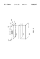
- FIG. 2 is an exploded perspective view of the bottom of the palm rest of FIG. 1, illustrating the insertion of a battery into an opening in the bottom of the palm rest.
- FIG. 3 is a block circuit diagram of the electrical connections between the components of the palm rest of FIG. 1.
- FIG. 4 is a block diagram of the connections between the components of the computer of FIG. 1.
- FIG. 1 shows a front perspective of a portable computer 110 generally small enough to carry in a briefcase, such as a Gateway 2000 ColorbookTM 2 , and a detachable palm rest 150 that locks into position in front of the computer 110 at the natural resting location of the user's palms while typing.
- a briefcase such as a Gateway 2000 ColorbookTM 2
- a detachable palm rest 150 that locks into position in front of the computer 110 at the natural resting location of the user's palms while typing.
- the electrical contacts 115 and 116 are be disposed anywhere on the edge of the computer case 111 so long as they mate with corresponding electrical contacts disposed on the palm rest 150 which are described below. Further embodiments comprise a single electrical contact, or more than two contacts for additional signal connections, such as an additional ground, depending on the arrangement and location of the electrical circuitry of the computer 110 and the palm rest 150 as shown in FIGS. 3 and 4.
- Palm rest 150 comprises a palm rest housing 151 having latch hooks 152 and 153 formed to fit and automatically lock into the latch slots 112 and 113 on the computer case 111.
- the latch hooks 151 and 152 are disengaged by two quick release buttons 154 and 155 (shown in FIG. 2.), one release button is positioned on each side of the housing 151, and operate as a fulcrum to lift the latches against a spring located within housing 151 which biases the latches in place.
- a battery status indicator 156 is bonded into the housing 151.
- latches 152 and 153 are hinged to fold toward each other, thereby reducing the space required to store the palm rest.
- FIG. 2 shows a perspective view of the back and bottom of palm rest housing 151.
- a protruding structure 213 is molded on the back of the housing 151 to fit into cutout 117.
- Electrical contacts 211 and 212 are positioned on the protruding structure 213 so that they mate with electrical contacts 115 and 116 in cutout 117 on the computer case 111 to form a firm electrical connection.
- the contacts are spring biased such that the springs compress when the palm rest is attached to the lap-top, providing better electrical contact.
- the molding process also creates an opening 214 in the housing 151 sized and shaped to hold a standard lap-top battery 215 such as a nickel-metal hydride rechargeable battery model number 10HR4/SAU-KSO-2 (Sanyo Electric Co., Ltd.).
- a removable cover 216 fastens to the housing 151 to secure the battery 215 and seal the opening 214.
- the battery 215 and the housing 151 are molded as a single unit and the palm rest 150 itself becomes a replaceable component.
- the palm reset 150 in one embodiment is then covered in a suitable well padded fabric to enhance comfort for the user, leaving open the side of the palm rest which connects to the lap-top computer 110.
- electrical contacts 211 and 212 are provided integral to or along the outside edges of latch hooks 152 and/or 153. Mating electrical contacts 115 and 116 are then disposed within slots 112 and 113 to correspondingly couple to the palm rest contacts 211 and 212.
- FIG. 3 is a block diagram of the circuitry of palm top 150. Electrical contacts 211 and 212 are coupled to the positive and negative terminals of a battery 215.
- a standard power monitoring circuit 310 is coupled to the battery 215 and to a standard battery status indicator 156. The power monitoring circuit 310 constantly checks the power level of the battery 215 and relays the power status to the status indicator 156.
- the power monitoring circuit 310 and status indicator 156 are located in computer case 111 and coupled to electrical contacts 115 and 116. Suitable power monitoring circuitry and status indicators are in common use today for laptop computers.
- a connector and appropriate circuitry (not shown) is also provided for independently coupling the backup battery to AC power and charging it separately from the computer 110.
- FIG. 4 is a block diagram of the electrical circuitry of portable computer 110 showing industry standard connections between standard components of a personal computer, whether an Apple or an IBM-compatible machine, or some variant thereof comprising a system address/data and power bus 410, for distributing power and communicatively linking a central processing unit 411, a random access memory 412, a hard disk data storage device 413, a keyboard 119, and a display unit 120.
- a power controller 417 is also provided to select between batteries for use and for recharging.
- the power controller 417 is configured to receive external power via a standard jack coupled to an AC power adapter which is not shown.
- Power monitoring circuit 310 and status indicator 156 form a part of the power controller 417 in one embodiment.
- the power controller 417 comprises a standard power switching circuit 414 coupled to the system bus 410, to a primary battery 415 and to electrical contacts 115 and 116.
- the power switching circuit 414 detects and becomes active when a palm rest 150 containing a battery 215 is attached to the computer 110.
- the power switching circuit 414 also monitors the discharge state of the primary battery, and receives information about the discharge state of the palm rest battery from monitoring circuit 310. It switches distribution of power to the non-active battery when the active battery reaches a pre-defined discharge level.
- the power controller 417 further comprises a standard battery charging circuit 416 coupled to the primary battery 415, to the electrical contacts 115 and 116, and to the power switching circuit 414.
- the battery charging circuit 416 is activated when the computer 110 is connected to an external power source and recharges the non-active battery when both the primary battery 415 and battery 215 are present. When only the primary battery 415 is present, the battery charging circuit reverts to its standard function and recharges the primary battery 415.
- the power controller distributes power from both batteries, to utilize the peak current flow from any one battery.
- the primary battery becomes non-active whenever the palm rest battery is available for supplying power. If external power is available, the primary battery receives priority for recharging. This provides the benefit of optimizing the ability to power the lap-top when the palm rest is detached for increased portability.
Abstract
Description
Claims (15)
Priority Applications (1)
| Application Number | Priority Date | Filing Date | Title |
|---|---|---|---|
| US08/572,313 US5860015A (en) | 1995-12-14 | 1995-12-14 | Detachable palm rest with backup battery |
Applications Claiming Priority (1)
| Application Number | Priority Date | Filing Date | Title |
|---|---|---|---|
| US08/572,313 US5860015A (en) | 1995-12-14 | 1995-12-14 | Detachable palm rest with backup battery |
Publications (1)
| Publication Number | Publication Date |
|---|---|
| US5860015A true US5860015A (en) | 1999-01-12 |
Family
ID=24287273
Family Applications (1)
| Application Number | Title | Priority Date | Filing Date |
|---|---|---|---|
| US08/572,313 Expired - Fee Related US5860015A (en) | 1995-12-14 | 1995-12-14 | Detachable palm rest with backup battery |
Country Status (1)
| Country | Link |
|---|---|
| US (1) | US5860015A (en) |
Cited By (19)
| Publication number | Priority date | Publication date | Assignee | Title |
|---|---|---|---|---|
| US6167289A (en) * | 1998-02-20 | 2000-12-26 | Qualcomm Incorporated | Power supply assembly for portable phone |
| US6209105B1 (en) * | 1996-09-10 | 2001-03-27 | Canon Kabushiki Kaisha | Battery-driven electronic equipment system and power source control method therefor |
| US6516374B1 (en) * | 1999-04-13 | 2003-02-04 | International Business Machines Corporation | Method for docking/undocking a portable computer to/from an expansion unit |
| US20040234319A1 (en) * | 2003-05-07 | 2004-11-25 | Lee Dennis G. | Keyboard rack with palm rest |
| US20050110461A1 (en) * | 2000-08-01 | 2005-05-26 | Earthlink Communications | Mobile teaching system |
| US20050152106A1 (en) * | 2004-01-08 | 2005-07-14 | Apple Computer, Inc. | Quick release structures for a computer |
| US7035102B2 (en) | 2004-01-08 | 2006-04-25 | Apple Computer, Inc. | Apparatus for air cooling of an electronic device |
| GB2421126A (en) * | 2004-12-07 | 2006-06-14 | Theratech Inc | Auxiliary power supply for portable medical device |
| US7161495B1 (en) * | 2004-04-30 | 2007-01-09 | Network Applicance, Inc. | Alert for indicating validity of removable memory media |
| US20070182339A1 (en) * | 2004-01-23 | 2007-08-09 | Koninklijke Philips Electronic N.V. | High frequency driver for gas discharge lamp |
| US20090268401A1 (en) * | 2004-03-12 | 2009-10-29 | Apple Inc. | Camera latch |
| EP2290499A1 (en) * | 2009-08-26 | 2011-03-02 | Giga-Byte Technology Co., Ltd. | Detachable power converter for portable electronic devices |
| US20110063804A1 (en) * | 2009-09-12 | 2011-03-17 | Hou-Yuan Lin | Portable Electronic Device |
| US20110163844A1 (en) * | 2008-09-01 | 2011-07-07 | Gerd Reime | Identification element having an optical transponder |
| US20150089248A1 (en) * | 2013-09-22 | 2015-03-26 | Microsoft Corporation | Accessory Device Power Management |
| US20170164089A1 (en) * | 2015-12-07 | 2017-06-08 | Samsung Electronics Co., Ltd. | Electronic device and operating method thereof |
| US20220069595A1 (en) * | 2020-08-27 | 2022-03-03 | Koi Charging LLC | Laptop case with charging pad |
| US11832069B1 (en) | 2022-12-14 | 2023-11-28 | Dell Products L.P. | Information handling system speaker with dampened speaker signal interface |
| US11914428B1 (en) * | 2022-12-14 | 2024-02-27 | Dell Products L.P. | Portable information handling system keyboard assembly having separable palm rest |
Citations (24)
| Publication number | Priority date | Publication date | Assignee | Title |
|---|---|---|---|---|
| US5107401A (en) * | 1990-07-11 | 1992-04-21 | Samsung Electronics Co., Ltd. | Lap top computer with tilting mechanism consisting of a battery pack pivotally attached on a rear surface |
| US5163153A (en) * | 1989-06-12 | 1992-11-10 | Grid Systems Corporation | Low-power, standby mode computer |
| US5241680A (en) * | 1989-06-12 | 1993-08-31 | Grid Systems Corporation | Low-power, standby mode computer |
| US5293300A (en) * | 1992-12-02 | 1994-03-08 | Quanta Computer, Inc. | Portable computer with a detachable handle including a battery |
| US5323291A (en) * | 1992-10-15 | 1994-06-21 | Apple Computer, Inc. | Portable computer and docking station having an electromechanical docking/undocking mechanism and a plurality of cooperatively interacting failsafe mechanisms |
| US5333116A (en) * | 1990-05-04 | 1994-07-26 | Ast Research, Inc. | Combination laptop and pad computer |
| US5410141A (en) * | 1989-06-07 | 1995-04-25 | Norand | Hand-held data capture system with interchangable modules |
| US5475626A (en) * | 1992-03-12 | 1995-12-12 | Ing. C. Olivetti & C., S.P.A. | Portable computer with a simple power supply control of chargeable and non-rechargeable battery packs |
| US5485073A (en) * | 1989-12-28 | 1996-01-16 | Kabushiki Kaisha Toshiba | Personal computer for performing charge and switching control of different types of battery packs |
| US5487181A (en) * | 1992-10-28 | 1996-01-23 | Ericsson Ge Mobile Communications Inc. | Low power architecture for portable and mobile two-way radios |
| US5514946A (en) * | 1993-03-19 | 1996-05-07 | Compaq Computer Corp. | Battery pack including static memory and a timer for charge management |
| US5517434A (en) * | 1989-01-31 | 1996-05-14 | Norand Corporation | Data capture system with communicating and recharging docking apparatus and hand-held data terminal means cooperable therewith |
| US5532524A (en) * | 1994-05-11 | 1996-07-02 | Apple Computer, Inc. | Distributed power regulation in a portable computer to optimize heat dissipation and maximize battery run-time for various power modes |
| US5539876A (en) * | 1989-08-28 | 1996-07-23 | Kabushiki Kaisha Toshiba | Computer unit with a resume function |
| US5553294A (en) * | 1990-06-25 | 1996-09-03 | Kabushiki Kaisha Toshiba | Portable computer powered by rechargeable batteries |
| US5563493A (en) * | 1993-01-13 | 1996-10-08 | Fujitsu Limited | Power source system of portable information processing system using battery |
| US5566340A (en) * | 1991-02-14 | 1996-10-15 | Dell Usa L.P. | Portable computer system with adaptive power control parameters |
| US5592362A (en) * | 1993-10-29 | 1997-01-07 | Kabushiki Kaisha Toshiba | Electronic system having portable electronic apparatus and external expansion unit for expanding function of electronic apparatus |
| US5596482A (en) * | 1994-09-22 | 1997-01-21 | International Business Machines Corporation | Stowable, pivotally attached palm rest and handle for a notebook computer |
| US5604050A (en) * | 1995-06-13 | 1997-02-18 | Motorola Inc. | Latching mechanism and method of latching thereby |
| US5621299A (en) * | 1994-01-27 | 1997-04-15 | David A. Krall | Rechargeable battery power supply with load voltage sensing, selectable output voltage and a wrist rest |
| US5641588A (en) * | 1994-09-01 | 1997-06-24 | Aer Energy Resources, Inc. | Portable battery with a retrofitting projection and wrist rest for use externally of an electronic device |
| US5668570A (en) * | 1993-06-29 | 1997-09-16 | Ditzik; Richard J. | Desktop computer with adjustable flat panel screen |
| US5721933A (en) * | 1994-12-22 | 1998-02-24 | Texas Instruments Incorporated | Power management supply interface circuitry, systems and methods |
-
1995
- 1995-12-14 US US08/572,313 patent/US5860015A/en not_active Expired - Fee Related
Patent Citations (24)
| Publication number | Priority date | Publication date | Assignee | Title |
|---|---|---|---|---|
| US5517434A (en) * | 1989-01-31 | 1996-05-14 | Norand Corporation | Data capture system with communicating and recharging docking apparatus and hand-held data terminal means cooperable therewith |
| US5410141A (en) * | 1989-06-07 | 1995-04-25 | Norand | Hand-held data capture system with interchangable modules |
| US5163153A (en) * | 1989-06-12 | 1992-11-10 | Grid Systems Corporation | Low-power, standby mode computer |
| US5241680A (en) * | 1989-06-12 | 1993-08-31 | Grid Systems Corporation | Low-power, standby mode computer |
| US5539876A (en) * | 1989-08-28 | 1996-07-23 | Kabushiki Kaisha Toshiba | Computer unit with a resume function |
| US5485073A (en) * | 1989-12-28 | 1996-01-16 | Kabushiki Kaisha Toshiba | Personal computer for performing charge and switching control of different types of battery packs |
| US5333116A (en) * | 1990-05-04 | 1994-07-26 | Ast Research, Inc. | Combination laptop and pad computer |
| US5553294A (en) * | 1990-06-25 | 1996-09-03 | Kabushiki Kaisha Toshiba | Portable computer powered by rechargeable batteries |
| US5107401A (en) * | 1990-07-11 | 1992-04-21 | Samsung Electronics Co., Ltd. | Lap top computer with tilting mechanism consisting of a battery pack pivotally attached on a rear surface |
| US5566340A (en) * | 1991-02-14 | 1996-10-15 | Dell Usa L.P. | Portable computer system with adaptive power control parameters |
| US5475626A (en) * | 1992-03-12 | 1995-12-12 | Ing. C. Olivetti & C., S.P.A. | Portable computer with a simple power supply control of chargeable and non-rechargeable battery packs |
| US5323291A (en) * | 1992-10-15 | 1994-06-21 | Apple Computer, Inc. | Portable computer and docking station having an electromechanical docking/undocking mechanism and a plurality of cooperatively interacting failsafe mechanisms |
| US5487181A (en) * | 1992-10-28 | 1996-01-23 | Ericsson Ge Mobile Communications Inc. | Low power architecture for portable and mobile two-way radios |
| US5293300A (en) * | 1992-12-02 | 1994-03-08 | Quanta Computer, Inc. | Portable computer with a detachable handle including a battery |
| US5563493A (en) * | 1993-01-13 | 1996-10-08 | Fujitsu Limited | Power source system of portable information processing system using battery |
| US5514946A (en) * | 1993-03-19 | 1996-05-07 | Compaq Computer Corp. | Battery pack including static memory and a timer for charge management |
| US5668570A (en) * | 1993-06-29 | 1997-09-16 | Ditzik; Richard J. | Desktop computer with adjustable flat panel screen |
| US5592362A (en) * | 1993-10-29 | 1997-01-07 | Kabushiki Kaisha Toshiba | Electronic system having portable electronic apparatus and external expansion unit for expanding function of electronic apparatus |
| US5621299A (en) * | 1994-01-27 | 1997-04-15 | David A. Krall | Rechargeable battery power supply with load voltage sensing, selectable output voltage and a wrist rest |
| US5532524A (en) * | 1994-05-11 | 1996-07-02 | Apple Computer, Inc. | Distributed power regulation in a portable computer to optimize heat dissipation and maximize battery run-time for various power modes |
| US5641588A (en) * | 1994-09-01 | 1997-06-24 | Aer Energy Resources, Inc. | Portable battery with a retrofitting projection and wrist rest for use externally of an electronic device |
| US5596482A (en) * | 1994-09-22 | 1997-01-21 | International Business Machines Corporation | Stowable, pivotally attached palm rest and handle for a notebook computer |
| US5721933A (en) * | 1994-12-22 | 1998-02-24 | Texas Instruments Incorporated | Power management supply interface circuitry, systems and methods |
| US5604050A (en) * | 1995-06-13 | 1997-02-18 | Motorola Inc. | Latching mechanism and method of latching thereby |
Cited By (39)
| Publication number | Priority date | Publication date | Assignee | Title |
|---|---|---|---|---|
| US6209105B1 (en) * | 1996-09-10 | 2001-03-27 | Canon Kabushiki Kaisha | Battery-driven electronic equipment system and power source control method therefor |
| US6167289A (en) * | 1998-02-20 | 2000-12-26 | Qualcomm Incorporated | Power supply assembly for portable phone |
| US6516374B1 (en) * | 1999-04-13 | 2003-02-04 | International Business Machines Corporation | Method for docking/undocking a portable computer to/from an expansion unit |
| US7160113B2 (en) | 2000-08-01 | 2007-01-09 | Earthwalk Communication, Inc. | Mobile teaching system |
| US20050110461A1 (en) * | 2000-08-01 | 2005-05-26 | Earthlink Communications | Mobile teaching system |
| US20040234319A1 (en) * | 2003-05-07 | 2004-11-25 | Lee Dennis G. | Keyboard rack with palm rest |
| US20060139879A1 (en) * | 2004-01-08 | 2006-06-29 | Apple Computer, Inc. | Apparatus for air cooling of an electronic device |
| US9207724B2 (en) | 2004-01-08 | 2015-12-08 | Apple Inc. | Quick release structures for a memory drive |
| US20100138056A1 (en) * | 2004-01-08 | 2010-06-03 | Apple Inc. | Apparatus for air cooling of an electronic device |
| US8425286B2 (en) | 2004-01-08 | 2013-04-23 | Apple Inc. | Quick release structures for a computer |
| US7035102B2 (en) | 2004-01-08 | 2006-04-25 | Apple Computer, Inc. | Apparatus for air cooling of an electronic device |
| US7242576B2 (en) | 2004-01-08 | 2007-07-10 | Apple Inc. | Quick release structures for a computer |
| US7848105B2 (en) | 2004-01-08 | 2010-12-07 | Apple Inc. | Apparatus for air cooling of an electronic device |
| US20070201205A1 (en) * | 2004-01-08 | 2007-08-30 | Apple Inc. | Apparatus for air cooling of an electronic device |
| US7466547B2 (en) | 2004-01-08 | 2008-12-16 | Apple Inc. | Apparatus for air cooling of an electronic device |
| US20050152106A1 (en) * | 2004-01-08 | 2005-07-14 | Apple Computer, Inc. | Quick release structures for a computer |
| US7684192B2 (en) | 2004-01-08 | 2010-03-23 | Apple Inc. | Apparatus for air cooling of an electronic device |
| US7746002B2 (en) | 2004-01-23 | 2010-06-29 | Koninklijke Philips Electronics N.V. | High frequency driver for gas discharge lamp |
| US20070182339A1 (en) * | 2004-01-23 | 2007-08-09 | Koninklijke Philips Electronic N.V. | High frequency driver for gas discharge lamp |
| US20090268401A1 (en) * | 2004-03-12 | 2009-10-29 | Apple Inc. | Camera latch |
| US8035481B2 (en) * | 2004-03-12 | 2011-10-11 | Apple Inc. | Illuminable latch |
| US8384518B2 (en) | 2004-03-12 | 2013-02-26 | Apple Inc. | Illuminable latch |
| US7161495B1 (en) * | 2004-04-30 | 2007-01-09 | Network Applicance, Inc. | Alert for indicating validity of removable memory media |
| GB2421126A (en) * | 2004-12-07 | 2006-06-14 | Theratech Inc | Auxiliary power supply for portable medical device |
| US20110163844A1 (en) * | 2008-09-01 | 2011-07-07 | Gerd Reime | Identification element having an optical transponder |
| US10229351B2 (en) * | 2008-09-01 | 2019-03-12 | Gerd Reime | Identification element having an optical transponder |
| EP2290499A1 (en) * | 2009-08-26 | 2011-03-02 | Giga-Byte Technology Co., Ltd. | Detachable power converter for portable electronic devices |
| US20110063804A1 (en) * | 2009-09-12 | 2011-03-17 | Hou-Yuan Lin | Portable Electronic Device |
| CN105683861A (en) * | 2013-09-22 | 2016-06-15 | 微软技术许可有限责任公司 | Accessory device power management |
| US9594415B2 (en) * | 2013-09-22 | 2017-03-14 | Microsoft Technology Licensing, Llc | Accessory device power management |
| US20170160790A1 (en) * | 2013-09-22 | 2017-06-08 | Microsoft Technology Licensing, Llc | Accessory Device Power Management |
| US20150089248A1 (en) * | 2013-09-22 | 2015-03-26 | Microsoft Corporation | Accessory Device Power Management |
| CN105683861B (en) * | 2013-09-22 | 2019-04-09 | 微软技术许可有限责任公司 | Accessory device power management |
| US10317983B2 (en) * | 2013-09-22 | 2019-06-11 | Microsoft Technology Licensing, Llc | Accessory device power management |
| KR20210031774A (en) * | 2013-09-22 | 2021-03-22 | 마이크로소프트 테크놀로지 라이센싱, 엘엘씨 | Accessory device power management |
| US20170164089A1 (en) * | 2015-12-07 | 2017-06-08 | Samsung Electronics Co., Ltd. | Electronic device and operating method thereof |
| US20220069595A1 (en) * | 2020-08-27 | 2022-03-03 | Koi Charging LLC | Laptop case with charging pad |
| US11832069B1 (en) | 2022-12-14 | 2023-11-28 | Dell Products L.P. | Information handling system speaker with dampened speaker signal interface |
| US11914428B1 (en) * | 2022-12-14 | 2024-02-27 | Dell Products L.P. | Portable information handling system keyboard assembly having separable palm rest |
Similar Documents
| Publication | Publication Date | Title |
|---|---|---|
| US5860015A (en) | Detachable palm rest with backup battery | |
| US6045398A (en) | Battery accepting unit and battery pack | |
| EP0987620B1 (en) | Function extending apparatus, electronic apparatus and electronic system | |
| US6291967B1 (en) | Battery discriminating method, dry cell battery pack, and electronic device | |
| EP0731940B1 (en) | Modular portable computer | |
| EP1088436B1 (en) | Portable phone with imbedded battery | |
| US5148042A (en) | Small electronic device capable of switching batteries by releasing a battery locking mechanism | |
| US6617063B1 (en) | Battery unit and electronic apparatus | |
| US6285159B1 (en) | Portable computer usable with a specific battery pack or ordinary battery | |
| AU672476B2 (en) | Portable electronic computer with removable disk drive | |
| US20050213297A1 (en) | Extended peripheral battery pack for a tablet computer | |
| EP1648044B1 (en) | Battery for dockable electronic device | |
| WO2005043707A2 (en) | External battery pack | |
| US7380143B2 (en) | Battery system configurations for docking components | |
| JP2002124226A (en) | Information processing device capable of using secondary battery and dry battery, and dry battery pack attachable/detachable to/from this information processing device | |
| US6078164A (en) | Portable electronic appliance | |
| US6460947B1 (en) | Interchangable battery pack for a portable computer | |
| EP1116284B1 (en) | Battery card assembly for electrical apparatuses | |
| US6562510B1 (en) | Battery card and electrical apparatus using same battery card assembly | |
| JPH07249399A (en) | Power supply card device | |
| KR20040051379A (en) | Mobile Printer | |
| CN220208218U (en) | Leather sheath keyboard | |
| JPH0566857A (en) | Information processor | |
| JP3099930U (en) | Battery card and electric device using the battery card device | |
| JPH06245375A (en) | Information processor and power supply pack |
Legal Events
| Date | Code | Title | Description |
|---|---|---|---|
| AS | Assignment |
Owner name: GATEWAY 2000, INC., SOUTH DAKOTA Free format text: ASSIGNMENT OF ASSIGNORS INTEREST;ASSIGNOR:OLSON, ANTHONY;REEL/FRAME:008205/0539 Effective date: 19960903 |
|
| CC | Certificate of correction | ||
| CC | Certificate of correction | ||
| AS | Assignment |
Owner name: GATEWAY, INC., SOUTH DAKOTA Free format text: CHANGE OF NAME;ASSIGNOR:GATEWAY 2000, INC.;REEL/FRAME:011590/0750 Effective date: 19990601 |
|
| FPAY | Fee payment |
Year of fee payment: 4 |
|
| SULP | Surcharge for late payment | ||
| FPAY | Fee payment |
Year of fee payment: 8 |
|
| SULP | Surcharge for late payment |
Year of fee payment: 7 |
|
| REMI | Maintenance fee reminder mailed | ||
| LAPS | Lapse for failure to pay maintenance fees | ||
| STCH | Information on status: patent discontinuation |
Free format text: PATENT EXPIRED DUE TO NONPAYMENT OF MAINTENANCE FEES UNDER 37 CFR 1.362 |
|
| FP | Lapsed due to failure to pay maintenance fee |
Effective date: 20110112 |