US5844600A - Methods, apparatus, and systems for transporting multimedia conference data streams through a transport network - Google Patents
Methods, apparatus, and systems for transporting multimedia conference data streams through a transport network Download PDFInfo
- Publication number
- US5844600A US5844600A US08/529,009 US52900995A US5844600A US 5844600 A US5844600 A US 5844600A US 52900995 A US52900995 A US 52900995A US 5844600 A US5844600 A US 5844600A
- Authority
- US
- United States
- Prior art keywords
- audio
- video
- data stream
- audio data
- multimedia
- Prior art date
- Legal status (The legal status is an assumption and is not a legal conclusion. Google has not performed a legal analysis and makes no representation as to the accuracy of the status listed.)
- Expired - Lifetime
Links
Images


Classifications
-
- H—ELECTRICITY
- H04—ELECTRIC COMMUNICATION TECHNIQUE
- H04N—PICTORIAL COMMUNICATION, e.g. TELEVISION
- H04N21/00—Selective content distribution, e.g. interactive television or video on demand [VOD]
- H04N21/20—Servers specifically adapted for the distribution of content, e.g. VOD servers; Operations thereof
- H04N21/23—Processing of content or additional data; Elementary server operations; Server middleware
- H04N21/236—Assembling of a multiplex stream, e.g. transport stream, by combining a video stream with other content or additional data, e.g. inserting a URL [Uniform Resource Locator] into a video stream, multiplexing software data into a video stream; Remultiplexing of multiplex streams; Insertion of stuffing bits into the multiplex stream, e.g. to obtain a constant bit-rate; Assembling of a packetised elementary stream
- H04N21/2368—Multiplexing of audio and video streams
-
- H—ELECTRICITY
- H04—ELECTRIC COMMUNICATION TECHNIQUE
- H04N—PICTORIAL COMMUNICATION, e.g. TELEVISION
- H04N21/00—Selective content distribution, e.g. interactive television or video on demand [VOD]
- H04N21/20—Servers specifically adapted for the distribution of content, e.g. VOD servers; Operations thereof
- H04N21/23—Processing of content or additional data; Elementary server operations; Server middleware
- H04N21/242—Synchronization processes, e.g. processing of PCR [Program Clock References]
-
- H—ELECTRICITY
- H04—ELECTRIC COMMUNICATION TECHNIQUE
- H04N—PICTORIAL COMMUNICATION, e.g. TELEVISION
- H04N21/00—Selective content distribution, e.g. interactive television or video on demand [VOD]
- H04N21/40—Client devices specifically adapted for the reception of or interaction with content, e.g. set-top-box [STB]; Operations thereof
- H04N21/43—Processing of content or additional data, e.g. demultiplexing additional data from a digital video stream; Elementary client operations, e.g. monitoring of home network or synchronising decoder's clock; Client middleware
- H04N21/4302—Content synchronisation processes, e.g. decoder synchronisation
- H04N21/4305—Synchronising client clock from received content stream, e.g. locking decoder clock with encoder clock, extraction of the PCR packets
-
- H—ELECTRICITY
- H04—ELECTRIC COMMUNICATION TECHNIQUE
- H04N—PICTORIAL COMMUNICATION, e.g. TELEVISION
- H04N21/00—Selective content distribution, e.g. interactive television or video on demand [VOD]
- H04N21/40—Client devices specifically adapted for the reception of or interaction with content, e.g. set-top-box [STB]; Operations thereof
- H04N21/43—Processing of content or additional data, e.g. demultiplexing additional data from a digital video stream; Elementary client operations, e.g. monitoring of home network or synchronising decoder's clock; Client middleware
- H04N21/4302—Content synchronisation processes, e.g. decoder synchronisation
- H04N21/4307—Synchronising the rendering of multiple content streams or additional data on devices, e.g. synchronisation of audio on a mobile phone with the video output on the TV screen
- H04N21/43072—Synchronising the rendering of multiple content streams or additional data on devices, e.g. synchronisation of audio on a mobile phone with the video output on the TV screen of multiple content streams on the same device
-
- H—ELECTRICITY
- H04—ELECTRIC COMMUNICATION TECHNIQUE
- H04N—PICTORIAL COMMUNICATION, e.g. TELEVISION
- H04N21/00—Selective content distribution, e.g. interactive television or video on demand [VOD]
- H04N21/40—Client devices specifically adapted for the reception of or interaction with content, e.g. set-top-box [STB]; Operations thereof
- H04N21/43—Processing of content or additional data, e.g. demultiplexing additional data from a digital video stream; Elementary client operations, e.g. monitoring of home network or synchronising decoder's clock; Client middleware
- H04N21/434—Disassembling of a multiplex stream, e.g. demultiplexing audio and video streams, extraction of additional data from a video stream; Remultiplexing of multiplex streams; Extraction or processing of SI; Disassembling of packetised elementary stream
- H04N21/4341—Demultiplexing of audio and video streams
-
- H—ELECTRICITY
- H04—ELECTRIC COMMUNICATION TECHNIQUE
- H04N—PICTORIAL COMMUNICATION, e.g. TELEVISION
- H04N21/00—Selective content distribution, e.g. interactive television or video on demand [VOD]
- H04N21/60—Network structure or processes for video distribution between server and client or between remote clients; Control signalling between clients, server and network components; Transmission of management data between server and client, e.g. sending from server to client commands for recording incoming content stream; Communication details between server and client
- H04N21/63—Control signaling related to video distribution between client, server and network components; Network processes for video distribution between server and clients or between remote clients, e.g. transmitting basic layer and enhancement layers over different transmission paths, setting up a peer-to-peer communication via Internet between remote STB's; Communication protocols; Addressing
- H04N21/643—Communication protocols
- H04N21/64307—ATM
-
- H—ELECTRICITY
- H04—ELECTRIC COMMUNICATION TECHNIQUE
- H04N—PICTORIAL COMMUNICATION, e.g. TELEVISION
- H04N7/00—Television systems
- H04N7/14—Systems for two-way working
- H04N7/141—Systems for two-way working between two video terminals, e.g. videophone
- H04N7/147—Communication arrangements, e.g. identifying the communication as a video-communication, intermediate storage of the signals
-
- H—ELECTRICITY
- H04—ELECTRIC COMMUNICATION TECHNIQUE
- H04N—PICTORIAL COMMUNICATION, e.g. TELEVISION
- H04N7/00—Television systems
- H04N7/14—Systems for two-way working
- H04N7/15—Conference systems
- H04N7/152—Multipoint control units therefor
-
- H—ELECTRICITY
- H04—ELECTRIC COMMUNICATION TECHNIQUE
- H04N—PICTORIAL COMMUNICATION, e.g. TELEVISION
- H04N21/00—Selective content distribution, e.g. interactive television or video on demand [VOD]
- H04N21/20—Servers specifically adapted for the distribution of content, e.g. VOD servers; Operations thereof
- H04N21/25—Management operations performed by the server for facilitating the content distribution or administrating data related to end-users or client devices, e.g. end-user or client device authentication, learning user preferences for recommending movies
- H04N21/266—Channel or content management, e.g. generation and management of keys and entitlement messages in a conditional access system, merging a VOD unicast channel into a multicast channel
- H04N21/2665—Gathering content from different sources, e.g. Internet and satellite
Definitions
- the present invention relates broadly to telecommunications multimedia conferencing. More particularly, the present invention relates to methods, apparatus, and systems for the handling of video, audio, and other data generated by a multimedia conference.
- multimedia conferencing should be understood to include all multimedia multipoint communications, including standard conferencing, as well as distance learning, tele-training, etc.
- Multimedia communications can be utilized for a number of applications, and in different configurations.
- One configuration of recent interest has been multimedia conferencing, where several parties can communicate in a conference style.
- multimedia conferencing the video data is handled such that each party can see at least one of the other parties, while the audio data is handled such that each party can hear one, several, or all of the other parties.
- various telecommunications standards are presently being adopted by the ITU-T and ISO which govern the protocols of multimedia conferencing (see, e.g., ITU-T.120).
- various standards have been adopted for the compression of the video and audio data.
- the video (digital image) compression standards are the JPEG (Joint Photographic Experts Group) standards promulgated by the joint ISO/CCITT technical committee ISO/IEC JTC1/SC2/WG10, and the MPEG (Motion Picture Experts Group) standards promulgated by ISO under ISO/IEC 11172(MPEG-1) and ISO/IEC 13818(MPEG-2).
- the audio compression standards are the MPEG audio compression.
- other compression techniques such as ADPCM (adaptive differential pulse code modulation) are known.
- the audio, video, and other data streams generated by a user's system 12a are multiplexed together directly (as suggested by the H.320 recommendation) in the encoder section of a multimedia encoder/decoder (codec) 14 located at the source/terminal 16, and transported together as an indivisible stream through the transport network 20 (now proposed in ATM format) to a similar "peer" codec 24 at a remote location.
- the peer codec is either at the remote user site for a point-to-point conference, and/or at a multimedia bridge 26 for a multipoint conference.
- the multimedia bridge 26 which typically includes a codec/switch 24 and a controller 28, provides conference control (e.g., it determines the signal to be sent to each participant), audio mixing (bridging) and multicasting, audio level detection for conference control, video switching, video mixing (e.g., a quad split, or "continuous presence device” which combines multiple images for display together) when available and/or desirable, and video multicasting.
- conference control e.g., it determines the signal to be sent to each participant
- audio mixing bridging
- multicasting audio level detection for conference control
- video switching e.g., a quad split, or "continuous presence device” which combines multiple images for display together
- video multicasting e.g., a quad split, or "continuous presence device" which combines multiple images for display together
- the multimedia conference systems of the art are generally suitable for multimedia conferencing purposes, various components of the system are extremely expensive.
- the multimedia bridge 26 which must support the switching, multicasting, and processing of the audio and video data at high speeds is an extremely complex, and hence expensive piece of equipment.
- the prior art requires that all of the audio, video, and other data are routed together to the multimedia bridge in all multimedia conferencing applications, large bandwidths are utilized for a single conference. Indeed, the entire audio/video/data bandwidth must be provided over the entire route from each source/terminal of the conference, through the various nodes of the telecommunications network to the node with the multimedia bridge.
- Another object of the invention is to provide methods, apparatus, and systems for multimedia conferencing, where the audio data and video data generated in a conference are transported separately and recombined at each terminal.
- a multimedia conferencing system comprises a plurality of audio/video terminals which are coupled together via a telecommunications network, with the network including switches and an audio bridge.
- the audio/video terminals are provided with interface modules which receive local audio and video signals, process the signals, and provide separate streams of properly formatted audio data and video data to the network.
- the video data is switched in the network (i.e., routed) to its desired destination, while the audio data is first routed to the audio bridge for mixing, and then to the desired destination.
- the separate audio and video signals are processed and synchronized by the interface module of the destination and provided to the audio/video terminal.
- various different synchronization mechanisms for the audio and video data streams can be utilized, ranging from mechanisms which are simple to implement, to mechanisms which require significant information about the network.
- a simple synchronization mechanism assumes that the delay in the network (i.e., transmission times) for the audio and video are substantially identical, and that the video (de)coding delay is greater than the audio (de)coding delay by a substantially known amount (e.g., 50-80 milliseconds). In this situation, synchronization is obtained by delaying the audio by the substantially known amount (e.g., 65 milliseconds). Because human perception of an out-of-synch condition is limited to the audio and video being out of synch by at least ⁇ 25 milliseconds, in many situations, the simple synchronization mechanism is sufficient.
- clock information e.g., a time stamp
- the video coding delay can be determined, and applied to the audio data stream (which is assumed to be minimal).
- the difference between the determined video delay and the known audio delay can be applied to the audio signal.
- a third, and more complex mechanism for synchronization involves inserting a clock sample (time stamp) in the digitized audio and video streams.
- a clock sample time stamp
- the time stamp which relates to the video which is to be received at a particular terminal is utilized in conjunction with the mixed audio stream.
- the received video and audio stream time stamps are extracted and compared to local clocks, and a delay representing the differential of the comparisons is calculated and applied (preferably to the audio path).
- Yet another mechanism for synchronization involves utilizing the capabilities of an external controller which supervises the path over which the audio and video streams are directed.
- the external controller can provide the interface module receiving the audio and video streams with a "delta" delay which can be applied to the "faster" of the two data streams (typically the audio).
- a preferred aspect of the invention involves mapping the audio and video data streams into ATM cells, and utilizing the ATM network for switching or multicasting the video data stream.
- the bridge for mixing and switching the audio data stream may be located at any node of the ATM network, and may also include a video bridge for accommodating a "continuing presence device" and other video processing. However, in accord with the invention, even where a video bridge is provided, the audio and video data streams are not multiplexed.
- FIG. 1 is a high level diagram of a prior art multimedia conferencing system having a plurality of multimedia conferencing sites coupled by an ATM telecommunications network, with the diagram showing the audio/video data flow therein.
- FIG. 2a is a high level diagram of a first multimedia conferencing system with audio and video data flows according to the invention.
- FIG. 2b is a high level diagram of a second multimedia conferencing system with audio and video data flows according to the invention.
- FIG. 3 is a block diagram of a preferred network to terminal interface in accord with the invention.
- FIG. 4a is a flow chart representing the encoding of the audio data by the network to terminal interface of FIG. 3.
- FIG. 4b is a flow chart representing the encoding of the video data by the network to terminal interface of FIG. 3.
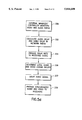
- FIGS. 5a-5d are flow charts of first, second, third, and fourth audio/video synchronization techniques according to the invention.
- FIGS. 6a and 6b are block diagrams of the source and sink time manager functions utilized in the synchronization techniques of FIGS. 5a-5d.
- FIG. 7 is a high level block diagram of the an audio/video bridge shown in FIG. 2b.
- FIG. 2a a first system 100 according to the invention is seen with the flow of audio and video data therein.
- a plurality of users 112a, 112b, 112c are each provided with codecs 114a, 114b, 114c, and multimedia source/terminals 116a, 116b, 116c.
- the codecs 114 which are described in greater detail with reference to FIGS. 3, 4a, and 4b, act as an interface between the network 120, and the source/terminals 116.
- the source/terminals typically include cameras 117, microphones 118, and computer terminals 119.
- the computer terminals 119 typically include a video monitor 119a, speakers 119b, keyboards 119c, etc. as is known in the art.
- video information which is to be transmitted is obtained by the camera or other video source 117 of a user 112, provided to the respective codec 114 of that user for processing, and then sent via the network 120 to its destination.
- the audio information is obtained by the microphone 118 (or other means), provided to the codec 114 for processing, and then separately sent via the network 120 to its destination.
- the audio information may be sent to an audio bridge 130 located at a first node of the network 120, while the video information may be sent to an ATM routing switch 140 located at another node of the ATM network 120.
- the audio bridge 130 generally includes a switch 132 and an audio processing block 134.
- the audio information may be decoded by a codec and mixed under control of a controller 136 with the audio information of other users of the multimedia conference.
- the audio mixing involves summing, or weighting and summing the audio of all of the audio signals of the users in the conference, and then subtracting the source audio signal of the destination.
- the so-obtained mixed audio information may then be coded by the codec and forwarded to its destination.
- the video information is typically simply routed, or multicast and routed to its destination(s).
- the video information being received is provided to the user's codec 114 for processing, and then provided to the video monitor 119a.
- the separately received mixed audio information is likewise sent to the codec 114 for processing, and then provided to the speaker 119b.
- the audio information is synchronized with the video information according to any desired synchronization technique, prior to being provided to the speaker 119b.
- FIG. 2b where like numerals indicate like elements
- the video bridge 150 may be located at the same location as the audio bridge 130, and will typically include a video switch 152 and video controller circuitry 154 (additional details being described below with reference to FIG. 7).
- a video bridge 150 is provided at the same location as the audio bridge 130, there are still advantages to separately transporting the audio and video data, as opposed to multiplexing them together.
- an audio source/terminal 116d is provided without video capability.
- the audio source/terminal 116d is coupled via an audio codec 115 to the ATM network 120 via a relatively low bandwidth line (e.g., a T1, or a regular copper telephone line which is coupled to a network analog-to-ATM codec).
- a relatively low bandwidth line e.g., a T1
- a regular copper telephone line which is coupled to a network analog-to-ATM codec.
- audio information provided by the source/terminal 116d is provided to the audio bridge 130 where it is mixed with the other audio signals which are intended for receipt by audio source/terminal 116d; and an appropriate mixed audio signal is sent from the audio bridge 130 to the audio source/terminal 116 without extraneous video information being multiplexed into the audio data stream.
- the codec 114 generally includes audio circuitry 200, video circuitry 220, modem type data circuitry 240, and a main processor or host 250 with an associated bus 252 and associated circuitry such as a boot PROM 254, flash memory 256, SRAM 258, a local manager interface 260, a timer 262, a watchdog circuit 264, and a management port UART 266.
- the boot PROM 254 stores the code which boots the main processor 250.
- the flash memory 256 is typically utilized to hold the main code and static configuration information.
- the RAM 258 is typically a dynamic RAM for running the code and temporarily storing data.
- the timer 262 provides clock signals for the operating system, while the watchdog 264 performs reset functions.
- the management port UART 266 is provided for access by a system manager (not shown) to the codec, while the local management interface 260 provides the codec with the capability of interfacing with a local management device (not shown).
- the audio circuitry 200 includes an analog to digital converter 202, an audio codec interface 204, an audio source time manager 206, an audio packet buffer SRAM 210, a packet buffer and DMA controller 212, an audio channel output interface 214, an audio channel input interface 216, an audio presentation time manager 217, and a digital to analog converter 218.
- the video circuitry 220 includes a composite NTSC/PAL video decoder 222, a JPEG compressor 224, a video source time manager 226, an outgoing packet buffer SRAM 227, an outgoing video packet buffer and DMA controller 228, a video channel output interface 229, and a video channel input interface 231, an incoming packet buffer and DMA controller 232, an incoming packet buffer SRAM 233, a JPEG decompressor 234, a composite NTSC/PAL video encoder 236, a video presentation time manager 238, and a video sync generator 239.
- the data circuitry 240 includes a data channel port UART 242, a data packet buffer and DMA controller 244 with an associated data packet buffer RAM 245, a data channel output interface 246, and a data channel input interface 248.
- outgoing audio information received from a microphone(s) or other audio source is applied to the analog to digital converter 202 which simultaneously provides the digital audio data to the audio codec interface 204 and, in accord with a preferred aspect of the invention, provides a reference clock to the audio source time manager 206.
- the audio codec interface 204 converts the format of the data received from the A/D converter so that the data may be properly provided to the packet buffer SRAM 210 under control of the packet buffer and DMA (direct memory access) controller.
- the main processor 250 provides a PES (Program Elementary Stream) header to the SRAM 210 to effectively generate PES formatted packet.
- PES Program Elementary Stream
- the packet buffer and DMA controller 212 controls the movement of the packetized audio data from the SRAM 210 to the channel output interface 214 as required.
- the channel output interface 214 places the data in a desired format (e.g., a Transport Stream (TS) format, or an ATM format) by inserting a system time indicator (provided by the audio source time manager) into the signal, and provides the desired overhead bits or bytes (including OAM where appropriate).
- a desired format e.g., a Transport Stream (TS) format, or an ATM format
- a system time indicator provided by the audio source time manager
- the channel output interface 214 implements a serial channel physical interface by receiving the parallel stream of data from the buffer controller, and converting the parallel stream into a serial stream with an accompanying clock, etc.
- Incoming audio information is received by the audio channel input interface 216 which frames on the incoming (TS) cell, checks the headers for errors, passes the payload in byte wide format (parallel format) to the packet buffer and DMA controller 212, and passes a time reference marker (Program Clock Reference value - PCR) to the audio presentation time manager 217.
- the DMA controller 212 places the payload in desired locations in the SRAM 210.
- the DMA controller takes the data out of the SRAM 210 and provides it to the audio codec interface 204, which reformats the data into a serial stream for digital to analog conversion by the D/A converter 218.
- the presentation time manager 217 is provided to recover a local clock.
- the main processor 250 controls the delay of the audio information by indicating to the DMA controller 212 how much time delay to introduce in the SRAM buffers 210, in order to synchronize the audio signal with the video signal.
- the video circuitry 220 processes and outputs the video signals separately from the audio circuitry 200. As seen in FIGS. 3 and 4b, outgoing video information is received by the video circuitry 220 as a composite analog input.
- the composite input is decoded by the composite decoder 222 which provides digital luminance and color difference signals to the video compressor 224, and horizontal and vertical synch and a field indicator to the video source time manager 226.
- the video compressor 224 as shown is a JPEG compressor which compresses the data, and generates a JPEG frame with start of image and end of image markers (see FIG. 4b).
- the video compressor 224 puts the framed compressed data in parallel format, so that the buffer controller 228 can place the compressed data into the packet buffer SRAM 227.
- the host main processor 250
- the packet buffer and DMA controller 228 provides the channel output interface 229 with the PES packet data at a constant rate. If sufficient data is not available in the packet buffer SRAM 227, the channel output interface 229 generates an "idle cell".
- the channel output interface 229 places the data in a desired format (e.g., TS or ATM format) by inserting a system time indicator (provided by the video source time manager 226) into the signal, and provides the desired overhead bits or bytes (including OAM where appropriate).
- a desired format e.g., TS or ATM format
- the channel output interface 229 implements a serial channel physical interface by receiving the parallel stream of data from the buffer controller 228, and converting the parallel stream into a serial stream with an accompanying clock, etc.
- video data is obtained at the video channel input interface 231 which frames on the incoming (TS) cell, checks the headers for errors, passes the payload in byte wide format (parallel format) to the packet buffer and DMA controller 232, and passes a time reference marker to the video presentation time manager 238.
- the DMA controller 232 places the payload in desired locations in the SRAM 233.
- the JPEG decompressor 234 indicates that the next video field is required for display
- the DMA controller 232 provides the buffered compressed video from the head of the buffer to the JPEG decompressor 234.
- the JPEG decompressor 234 decompresses the data, and provides digital luminance and color difference signals to the composite video encoder 236.
- the composite video encoder 236 operates based on the video timing signals (horizontal line timing or H, vertical field timing or V, and the field indicator) generated by the sync generator, based on the sample clock recovered by the presentation time manager from the channel PCR.
- the composite video encoder 236 in turn indicates to the JPEG decompressor when it requires video data for the next video field, and which field is required. Based on these timing signals and the decompressed video data, the composite video encoder generates the analog video output for the video monitor 119a.
- the presentation time manager serves to recover the video sample clock and local (sink) Program Clock (PC) from the video channel PCR, and also to make available to the host processor the sampled values of the PC for comparison to the received Presentation Time Stamp (PTS) in the PES headers.
- PC Program Clock
- the main processor 250 can determine when data which is being placed in the packet buffer RAM 233 is going to be output to a video monitor. This information is useful in synchronizing the audio and video signals as discussed in detail below.
- the video circuitry 220 utilizes two packet buffer SRAMs 227, 233, and two packet buffer and DMA controllers 228, 232, as compared to a single packet buffer SRAM 210 and packet buffer and DMA controller 212 for the audio.
- the two SRAMs and controllers for the video are provided because the amount of video data is large as compared to the audio data.
- the audio data does not require use of two SRAMs and controllers because it is able to share a common resource for both directions of signal flow.
- any terminal such as terminal 116d (see FIG. 1) which is audio only, need only include the audio portion (and typically, as described below, the data portion) of the circuitry of FIG. 3.
- audio-only terminals can utilize relatively less expensive low bandwidth lines.
- the codec 114 also codes and decodes non-video and non-audio serial data.
- the serial data is received by a conventional Universal Asynchronous Receiver/Transmitter (UART) 242 and is provided to the main processor 250.
- the main processor preferably runs a Serial Line Internet Protocol (SLIP), which brings the serial data to an Internet Protocol (IP) stack in the host.
- SLIP Serial Line Internet Protocol
- IP Internet Protocol
- the IP protocol data is packetized and may be sent to the data packet buffer SRAM 245 via the packet buffer and DMA controller 244, or alternatively sent to the audio packet buffer SRAM 210 via the audio DMA controller 212.
- a separate DMA controller 244 provides the packetized data to a separate channel output interface 246.
- the IP protocol data is packetized and sent to the audio packet buffer SRAM 210, the audio data and serial data are effectively time division multiplexed according to a desired frame, and the audio data and serial data are output together in a time division multiplexed manner over the channel output interface 214.
- the handling of incoming serial data depends on whether the serial data is multiplexed with the audio data, or separately provided.
- the channel input interface 248 receives the data, frames on the incoming cell, checks the headers for errors, and passes the payload in byte wide format (parallel format) to the packet buffer and DMA controller 244 which forwards it to the SRAM 245.
- the main processor 250 then obtains the IP packet data, decodes it, and provides the data to the UART 242 for local use.
- the most simple synchronization mechanism assumes that the delay in the network (i.e., transmission times) for the audio and video are substantially identical, and that the video (de)coding delay is greater than the audio (de)coding delay by a substantially known amount (e.g., 50-80 milliseconds). In this situation, synchronization is obtained by delaying the audio by the substantially known amount (e.g., 65 milliseconds).
- the audio information and video information are separately and asynchronously obtained.
- the video information is decompressed and otherwise processed at 303a, while the audio information is separately processed at 303b.
- the audio information is delayed by a predetermined length of time (e.g., 65 milliseconds) which is substantially equal to delay introduced in the video stream by the decompression processing.
- a predetermined length of time e.g. 65 milliseconds
- the video information and the delayed audio information which is now substantially synchronized with the video information are provided to the audio/video system of the receiver. Because human perception of an out-of-synch condition is limited to the audio and video being out of synch by at least ⁇ 25 milliseconds, in many situations, the simple synchronization mechanism of FIG. 5a is sufficient.
- clock information (e.g., a time stamp) can be provided in the video data stream.
- the video coding delay can be determined, and applied to the audio data stream.
- the difference between the determined video delay and the known audio delay can be applied to the audio signal.
- a presentation time stamp is inserted into the video information at the source.
- the video information with the time stamp is switched and otherwise transported through the network and the audio information is separately switched, bridged, and otherwise transported through the network.
- the video information containing a time stamp, and the audio information are separately and asynchronously obtained at the destination.
- the time stamp for the video information is recovered, and at 315a, the video information is decompressed and otherwise processed.
- the audio information is separately processed at 313b.
- the time stamp for the video information is compared against a local clock in order to determine the video coding (i.e., compression, plus buffer delays, plus decompression) delay. The result of that comparison, or a function thereof, is then used to delay the audio signal at 317b.
- the difference between the video coding delay and the audio coding delay, or a function thereof, may be used to delay the audio signal at 317b.
- the video information and the delayed audio information which is now substantially synchronized with the video information are provided to the audio/video system of the receiver.
- a third, and more complex mechanism for synchronization involves inserting a clock sample (time stamp) in both the digitized audio and video streams.
- the time stamp which relates to the video which is to be received at a particular terminal is utilized in conjunction with the mixed audio stream.
- the received video and audio stream time stamps are extracted, compared to local clocks, and the comparisons are compared, and a delay representing the differential delay is calculated and applied (preferably to the audio path).
- source video information is provided with a video presentation time stamp
- source audio information is separately provided with an audio time stamp.
- the audio information with its time stamp, and the video information with its time stamp are separately switched, and/or bridged, and otherwise transported through the network.
- the video information containing the video time stamp, and the audio information containing the audio time stamp are separately and asynchronously obtained.
- the time stamp for the video information is recovered, while at 323b, the time stamp for the audio information is recovered.
- the video information is decompressed and otherwise processed, while at 325b, the audio information is separately processed.
- the audio time stamp is compared to a local clock, while at 326b, the video time stamp is compared to the local clock. The comparisons are then themselves compared at 327 and the result is used to delay the audio signal at 328.
- the video information and the delayed audio information which is now substantially synchronized with the video information are provided to the audio/video system of the receiver.
- a fourth mechanism for synchronization involves utilizing the capabilities of an external controller which supervises the path over which the audio and video streams are directed.
- the external controller can provide the interface module receiving the audio and video streams with a "delta" delay which can be applied to the "faster" of the two data streams (typically the audio).
- the external (management) controller obtains information regarding the paths for the video and audio information.
- the external controller uses knowledge of the delay at and between each node, and the delay in each switch or bridge, the external controller calculates the delay for the audio information and the delay for the video information up to the delay in the receiving codec.
- the external controller provides the delay information (or the delta) to the codec of the receiving terminal (typically via the management port UART of that codec).
- the main processor of the codec uses local information regarding the audio and video coding delays in the codec to calculate at 336 the difference between the total audio delay and the total video delay for the audio and video information, and at 337 delays either the audio or video signals (usually the audio) accordingly.
- the video information and the delayed audio information which is now substantially synchronized with the video information are provided to the audio/video system of the receiver. It will be appreciated that instead of having the main processor of the codec calculate at 336 the delta delay, the codec could provide the management controller with information regarding its internal audio and video delays, and the management controller could calculate and provide the total delays or delay difference to the codec.
- FIGS. 6a, and 6b The mechanisms for generating and utilizing time stamps which are used as discussed above with reference to FIGS. 5b and 5c, and which are indicated with respect to the video source time manager 226, video presentation time manager 238, audio source time manager 206 and audio presentation time manager 217 of FIG. 3, are seen in FIGS. 6a, and 6b.
- a time stamp generation diagram is seen in FIG. 6a which relates closely to FIGS. 4a and 4b, and is shown as being generic for both audio and video time stamp generation.
- the flow of data seen is FIG. 6a is essentially that seen in FIGS. 3, 4a and 4b.
- data from the audio or video source 350 is optionally compressed at 352 (with the video using, for example, JPEG or MPEG compression, and the audio using, for example, MPEG or ADPCM compression), and the data or compressed data is then packetized 354 in the buffer 356 and transported as cells 358.
- a "presentation" time stamp (PTS) is added which may be used for audio/video synchronization purposes as described above with reference to FIGS. 5b and 5c.
- PCR program clock reference
- the presentation time stamp PTS is generated by sampling a source program clock at fixed locations in the data stream.
- the data generated by the source is generally accompanied by a clock CLK, which is provided to the source program clock 360.
- the source program clock 360 is preferably embodied as a free running counter.
- the source At given fixed locations in the data stream (e.g., the Field 1 indicator for video; or an arbitrary regular time interval for audio), the source generates a control signal or "tic" which causes a latch 362 to sample and latch in the count of the source program clock 360.
- the count sampled by the latch 362 is taken as the PTS, and is placed into the header of the PES packet. It should be appreciated that the placement of the PTS into the PES packet may actually be accomplished by adding the PTS into predetermined buffer locations; i.e., the packet is formed in the buffer.
- the count of the source program clock 360 is also used as a program clock reference (PCR).
- PCR program clock reference
- the count of the program clock 360 is taken and inserted as the PCR into the overhead of the transport cell. It should be appreciated that the difference in the PTS and PCR values represents the encoding delay; i.e., the delay introduced by compression and transmit buffering.
- the receiver 370 strips off the transport cell overhead OH (including the PCR), and sends the payload data to the buffer 372.
- the payload is then removed from the buffer 372 as PES packets, and the PES header is stripped off the packet at 374 with the PTS value being stored for later use as described below.
- the data is then decompressed at 376 (if it was originally compressed), and provided to the data sink 378.
- a sink program clock which is preferably synchronized to the source program clock is generated by providing the PCR values stripped out of the transport cell overhead to a phase lock loop (PLL) 380.
- the phase lock loop includes a subtractor 382, a voltage controlled oscillator 384, and the sink program clock 386, with the output of the sink program clock 386 being provided to the subtractor 382 as feedback.
- the output of the voltage controlled oscillator 384 will be nominally the same frequency CLK as that of the source 350, and this clock is provided to the sink 378.
- the sink When the sink is about to display the data to which is associated the PTS value (e.g., the beginning of a video scan), the sink provides a control "tic" which causes a latch 388 to sample and latch the value of the sink program clock 386.
- the value of the PTS value (from 374), and the value of the latch are then provided to subtractor 390, with the difference between values representing the actual coding delay.
- the coding delay includes the encoding delay plus the decoding delay, but does not include channel delay. This may be understood by recognizing that the count of the sink program clock 386 is synchronized to the source program clock 360.
- the encoding delay (PTS - PCR) is already built into the sink program clock, and the additional delay in the decoding represented by the difference of PTS and the sink program clock value at the time of display is added to that built-in delay.
- the coding delay (as output by the subtractor 390 of FIG. 6b) is applied to the audio signal in order to substantially synchronize the audio and video signals.
- the method of FIG. 5b generally assumes that the audio signal coding delay is essentially negligible.
- the audio presentation time manager 217 (FIG. 3) does not need to process the PTS information and does not need to generate a coding delay.
- FIG. 6b as it relates to the audio signal, does not require the latch 388, or the subtractor 390.
- the coding delay as determined by the video presentation time manager 238 (FIG. 3) and in accord with FIG. 6b, is provided to the DMA controller (FIG. 3) in order to appropriately delay the audio data in the buffer.
- the audio and video subsystems will share a sample clock reconstruction portion of the logic; i.e., there will be only one source program clock which is used by both the video and audio source time managers, and only one sink program clock which is used by both the video and audio presentation time managers. While it does not matter whether the audio or video is used to convey the program clock reference (PCR), for purposes of discussion, it will be assumed that the video channel is used.
- PCR program clock reference
- the differential delay between the audio and video signals can be measured by comparing corresponding audio and video PTS values as they are presented to the respective sinks.
- This is an oversimplification due to the need to compensate for compression and decompression processing and the fact that audio and video packets will not occur at the same rate; nor will they have the PTS applied at corresponding points in time.
- the sink program clock is used in order to adjust the raw PTS values to corresponding points in time before the delay comparison is made.
- the video coding delay measurement (as output by the subtractor 390) is made as discussed above (with reference to FIGS. 5b, 6a, and 6b), with the assumption that the video channel carries the PCR.
- the same technique is then applied to the audio PTS, with the output of the subtractor 390 providing not just the audio coding delay, but the coding delay plus any difference between the audio and video channels.
- the audio buffer delay is then adjusted to make the audio delay (audio coding plus channel delta) equal to the video coding delay.
- the output of the subtractor 390 for the video presentation manager is compared with (subtracted from) the output of the subtractor 390 for the audio presentation manager, and the difference is applied as additional delay to the audio signal.
- the audio and video bridge 130/150 includes a cross-connect switching section including an audio cross-connect ATM switch 132, a video cross-connect ATM switch 152, and a data cross-connect ATM switch 172. If video processing is not required, the video cross-connect switch 152 routes the video data, and does not forward it to the processing section 401 of the bridge. However, if video processing such as quad-split or continuous presence is required, the switched video data is forwarded through the video ports 453a, 453b, . . . to the video processing unit 154 which is directly under the control of the session management and control block 136a, and indirectly under the control of the management and control interface 136b.
- the audio information is likewise cross-connected by audio switch 132, and forwarded to the processing section 401 for processing.
- the audio information is received by audio ports 433a, 433b, . . . , to the audio processing unit 134 which is directly under the control of the session management and control block 136a, and indirectly under the control of the management and control interface 136b.
- the audio information received from the different audio ports 433 involved in the conference will be summed, or weighted and summed, and then the source audio signal of the destination will be subtracted from the sum.
- the weighting of information, and other control of the conference is provided to the audio processing block 134 by the controller 136. That information, in turn, is obtained from the data processing unit 474 which receives the command through the data ports 473.
- the modem 497, and Ethernet link 498 are external connections which permit a system controller (not shown) to access the management and control interface 136b.
- the operations, administration and maintenance section (OA&M) 499 is involved in usage statistics collection, system configuration, and error or message logging.
- the invention requires that the audio and video data streams be handled and processed separately, it will be appreciated that it may be appropriate in some circumstances to time division multiplex the audio and video data streams generated at a source onto a single network interface "wire" (i.e., a "local" channel segment); provided of course that the data is divided into separate frames or cells so that the actual channels (VCC) for the audio and video are different.
- VCC virtual channels
- the routing of the audio and video data streams may cause the data streams at certain times to be on the same physical connection, the audio and video data streams must be capable of being routed and switched independently.
- four different synchronization mechanisms for synchronizing the audio and video data streams at the terminal have been described, other synchronization mechanisms could be utilized.
Abstract
Description
Claims (20)
Priority Applications (4)
| Application Number | Priority Date | Filing Date | Title |
|---|---|---|---|
| US08/529,009 US5844600A (en) | 1995-09-15 | 1995-09-15 | Methods, apparatus, and systems for transporting multimedia conference data streams through a transport network |
| CA002231780A CA2231780C (en) | 1995-09-15 | 1996-09-12 | Telecommunications multimedia conferencing system and method |
| EP96930840A EP0850538A4 (en) | 1995-09-15 | 1996-09-12 | Telecommunications multimedia conferencing system and method |
| PCT/US1996/014621 WO1997010674A1 (en) | 1995-09-15 | 1996-09-12 | Telecommunications multimedia conferencing system and method |
Applications Claiming Priority (1)
| Application Number | Priority Date | Filing Date | Title |
|---|---|---|---|
| US08/529,009 US5844600A (en) | 1995-09-15 | 1995-09-15 | Methods, apparatus, and systems for transporting multimedia conference data streams through a transport network |
Publications (1)
| Publication Number | Publication Date |
|---|---|
| US5844600A true US5844600A (en) | 1998-12-01 |
Family
ID=24108129
Family Applications (1)
| Application Number | Title | Priority Date | Filing Date |
|---|---|---|---|
| US08/529,009 Expired - Lifetime US5844600A (en) | 1995-09-15 | 1995-09-15 | Methods, apparatus, and systems for transporting multimedia conference data streams through a transport network |
Country Status (4)
| Country | Link |
|---|---|
| US (1) | US5844600A (en) |
| EP (1) | EP0850538A4 (en) |
| CA (1) | CA2231780C (en) |
| WO (1) | WO1997010674A1 (en) |
Cited By (164)
| Publication number | Priority date | Publication date | Assignee | Title |
|---|---|---|---|---|
| US5987518A (en) * | 1996-10-28 | 1999-11-16 | General Instrument Corporation | Method and apparatus for communicating internet protocol data over a broadband MPEG channel |
| US5999966A (en) * | 1997-10-07 | 1999-12-07 | Mcdougall; Floyd | Control network-directed video conferencing switching system and method |
| US6006241A (en) * | 1997-03-14 | 1999-12-21 | Microsoft Corporation | Production of a video stream with synchronized annotations over a computer network |
| US6049531A (en) * | 1997-07-14 | 2000-04-11 | At&T Corp | Real-time multimedia conferencing over an ATM network using an intelligent ATM ADSL modem and ADSL access |
| WO2000072164A1 (en) * | 1999-05-20 | 2000-11-30 | Rotor Communications Corporation | Method and apparatus for synchronizing the broadcast content of interactive internet-based programs |
| US6167033A (en) * | 1997-10-28 | 2000-12-26 | Inventec Corp. | Multiple-party network communication system and method of troubleshooting thereof |
| US6172988B1 (en) * | 1996-01-31 | 2001-01-09 | Tiernan Communications, Inc. | Method for universal messaging and multiplexing of video, audio, and data streams |
| EP1087579A2 (en) * | 1999-09-22 | 2001-03-28 | NTT DoCoMo, Inc. | Gateway for reducing delay jitter and method for data transfer therein |
| US6233428B1 (en) * | 1997-09-17 | 2001-05-15 | Bruce Fryer | System and method for distribution of child care training materials and remote monitoring of child care centers |
| US6278691B1 (en) * | 1997-02-17 | 2001-08-21 | Matsushita Electric Industrial Co., Ltd. | Communications system |
| US6330285B1 (en) * | 1998-02-11 | 2001-12-11 | Tektronix, Inc. | Video clock and framing signal extraction by transport stream “snooping” |
| US6335927B1 (en) | 1996-11-18 | 2002-01-01 | Mci Communications Corporation | System and method for providing requested quality of service in a hybrid network |
| US20020015108A1 (en) * | 2000-03-17 | 2002-02-07 | Masatoshi Takashima | Data transmission method and data transmission system |
| US20020039143A1 (en) * | 2000-10-02 | 2002-04-04 | Mega Chips Corporation | Image processing circuit |
| US20020103919A1 (en) * | 2000-12-20 | 2002-08-01 | G. Wyndham Hannaway | Webcasting method and system for time-based synchronization of multiple, independent media streams |
| US6456594B1 (en) | 1996-10-31 | 2002-09-24 | Connect One, Llp | Multi-protocol communications routing optimization |
| US20020150123A1 (en) * | 2001-04-11 | 2002-10-17 | Cyber Operations, Llc | System and method for network delivery of low bit rate multimedia content |
| US6473404B1 (en) | 1998-11-24 | 2002-10-29 | Connect One, Inc. | Multi-protocol telecommunications routing optimization |
| US20020181459A1 (en) * | 2001-04-27 | 2002-12-05 | Matsushita Electric Industrial Co., Ltd. | Wireless communication apparatus |
| US6600745B1 (en) * | 1996-02-02 | 2003-07-29 | Marconi Communications Limited | Cell aligners |
| US20030142652A1 (en) * | 2002-01-29 | 2003-07-31 | Palm, Inc. | Dynamic networking modes method and apparatus |
| US20030142471A1 (en) * | 2002-01-29 | 2003-07-31 | Palm, Inc. | Replaceable cover for handheld computer |
| US20030158957A1 (en) * | 2002-01-23 | 2003-08-21 | Ali Abdolsalehi | Interactive internet browser based media broadcast |
| EP1341160A1 (en) * | 2002-03-01 | 2003-09-03 | Deutsche Thomson-Brandt Gmbh | Method and apparatus for encoding and for decoding a digital information signal |
| EP1341161A2 (en) * | 2002-03-01 | 2003-09-03 | Thomson Licensing S.A. | Method and apparatus for encoding and for decoding a digital information signal |
| US6631410B1 (en) * | 2000-03-16 | 2003-10-07 | Sharp Laboratories Of America, Inc. | Multimedia wired/wireless content synchronization system and method |
| US6690654B2 (en) | 1996-11-18 | 2004-02-10 | Mci Communications Corporation | Method and system for multi-media collaboration between remote parties |
| US6693663B1 (en) * | 2002-06-14 | 2004-02-17 | Scott C. Harris | Videoconferencing systems with recognition ability |
| US6693900B1 (en) * | 1998-05-19 | 2004-02-17 | Nokia Corporation | Variable bit rate transmission of AV signal in packet network |
| US20040075767A1 (en) * | 2002-10-22 | 2004-04-22 | Darren Neuman | A/V system and method supporting a pull data flow scheme |
| US6731625B1 (en) | 1997-02-10 | 2004-05-04 | Mci Communications Corporation | System, method and article of manufacture for a call back architecture in a hybrid network with support for internet telephony |
| WO2004052020A1 (en) * | 2002-12-04 | 2004-06-17 | Koninklijke Philips Electronics N.V. | Synchronization of signals |
| US6754181B1 (en) | 1996-11-18 | 2004-06-22 | Mci Communications Corporation | System and method for a directory service supporting a hybrid communication system architecture |
| US6778493B1 (en) | 2000-02-07 | 2004-08-17 | Sharp Laboratories Of America, Inc. | Real-time media content synchronization and transmission in packet network apparatus and method |
| US20040239754A1 (en) * | 2001-12-31 | 2004-12-02 | Yair Shachar | Systems and methods for videoconference and/or data collaboration initiation |
| US20040257758A1 (en) * | 2002-01-29 | 2004-12-23 | Palm, Inc. | Encasement for handheld computer |
| US20050006574A1 (en) * | 2003-06-26 | 2005-01-13 | Xerox Corporation | Position encoder |
| US6856613B1 (en) * | 1999-12-30 | 2005-02-15 | Cisco Technology, Inc. | Method and apparatus for throttling audio packets according to gateway processing capacity |
| US20050053089A1 (en) * | 2003-01-31 | 2005-03-10 | Alcatel | Audio and video data processing device for multimedia communication via a local network set up within an asynchronous network |
| US20050073574A1 (en) * | 2003-10-01 | 2005-04-07 | Krisbergh Hal M. | Videophone system and method |
| US20050078171A1 (en) * | 2003-10-08 | 2005-04-14 | Cisco Technology, Inc. A California Corporation | System and method for performing distributed video conferencing |
| US6922730B1 (en) * | 1999-12-21 | 2005-07-26 | Intel Corporation | Dedicated digital-to-analog network audio bridging system |
| US6940826B1 (en) * | 1999-12-30 | 2005-09-06 | Nortel Networks Limited | Apparatus and method for packet-based media communications |
| US20050213736A1 (en) * | 2001-12-31 | 2005-09-29 | Polycom, Inc. | Speakerphone establishing and using a second connection of graphics information |
| US20050213738A1 (en) * | 2001-12-31 | 2005-09-29 | Polycom, Inc. | Conference endpoint requesting and receiving billing information from a conference bridge |
| US20050213728A1 (en) * | 2001-12-31 | 2005-09-29 | Polycom, Inc. | Conference endpoint instructing a remote device to establish a new connection |
| US20050213733A1 (en) * | 2001-12-31 | 2005-09-29 | Polycom, Inc. | Speakerphone and conference bridge which receive and provide participant monitoring information |
| US20050213737A1 (en) * | 2000-12-26 | 2005-09-29 | Polycom, Inc. | Speakerphone transmitting password information to a remote device |
| US20050249244A1 (en) * | 2004-03-10 | 2005-11-10 | Kabushiki Kaisha Toshiba | Packet format |
| US20050248652A1 (en) * | 2003-10-08 | 2005-11-10 | Cisco Technology, Inc., A California Corporation | System and method for performing distributed video conferencing |
| US20050259623A1 (en) * | 2004-05-13 | 2005-11-24 | Harinath Garudadri | Delivery of information over a communication channel |
| US20060087554A1 (en) * | 2004-10-25 | 2006-04-27 | Boyd Sandra L | Systems and processes for scheduling and conducting audio/video communications |
| US20060092269A1 (en) * | 2003-10-08 | 2006-05-04 | Cisco Technology, Inc. | Dynamically switched and static multiple video streams for a multimedia conference |
| US7096037B2 (en) * | 2002-01-29 | 2006-08-22 | Palm, Inc. | Videoconferencing bandwidth management for a handheld computer system and method |
| US7096487B1 (en) * | 1999-10-27 | 2006-08-22 | Sedna Patent Services, Llc | Apparatus and method for combining realtime and non-realtime encoded content |
| US20060225106A1 (en) * | 2005-03-31 | 2006-10-05 | Bedingfield James C Sr | Presence detection in a bandwidth management system |
| US20060222015A1 (en) * | 2005-03-31 | 2006-10-05 | Kafka Henry J | Methods, systems, and devices for bandwidth conservation |
| US20060221826A1 (en) * | 2005-03-31 | 2006-10-05 | Bedingfield James C Sr | Methods, systems, and computer program products for providing traffic control services |
| US20060222008A1 (en) * | 2005-03-31 | 2006-10-05 | Aaron Jeffrey A | Methods, systems, and computer program products for implementing bandwidth control services |
| US7133896B2 (en) | 1997-03-31 | 2006-11-07 | West Corporation | Providing a presentation on a network |
| US20060250522A1 (en) * | 2005-05-04 | 2006-11-09 | Pace Micro Technology Plc | Television system |
| US7149686B1 (en) * | 2000-06-23 | 2006-12-12 | International Business Machines Corporation | System and method for eliminating synchronization errors in electronic audiovisual transmissions and presentations |
| US20060282184A1 (en) * | 2005-06-08 | 2006-12-14 | Polycom, Inc. | Voice interference correction for mixed voice and spread spectrum data signaling |
| US20070047626A1 (en) * | 2005-06-08 | 2007-03-01 | Polycom, Inc | Mixed voice and spread spectrum data signaling with multiplexing multiple users with cdma |
| US20070047624A1 (en) * | 2005-06-08 | 2007-03-01 | Polycom, Inc | Mixed voice and spread spectrum data signaling with enhanced concealment of data |
| US20070126929A1 (en) * | 2003-07-01 | 2007-06-07 | Lg Electronics Inc. | Method and apparatus for testing lip-sync of digital television receiver |
| US20070136772A1 (en) * | 2005-09-01 | 2007-06-14 | Weaver Timothy H | Methods, systems, and devices for bandwidth conservation |
| US20070133603A1 (en) * | 2005-09-01 | 2007-06-14 | Weaver Timothy H | Methods, systems, and devices for bandwidth conservation |
| US20070156924A1 (en) * | 2006-01-03 | 2007-07-05 | Cisco Technology, Inc. | Method and apparatus for transcoding and transrating in distributed video systems |
| US20070258459A1 (en) * | 2006-05-02 | 2007-11-08 | Harris Corporation | Method and system for QOS by proxy |
| US20070258486A1 (en) * | 2006-05-02 | 2007-11-08 | Harris Corporation | Systems and methods for close queuing to support quality of service |
| US20070268836A1 (en) * | 2006-05-18 | 2007-11-22 | Joonbum Byun | Method and system for quality monitoring of media over internet protocol (MOIP) |
| US7302396B1 (en) | 1999-04-27 | 2007-11-27 | Realnetworks, Inc. | System and method for cross-fading between audio streams |
| US20070274675A1 (en) * | 2003-12-01 | 2007-11-29 | Lg Electronics Inc. | Method and Apparatus for Transcoding Digital Audio/Video Streams |
| US20070282994A1 (en) * | 2006-05-31 | 2007-12-06 | Ted Beers | System and method for managing virtual collaboration systems |
| US20070291656A1 (en) * | 2006-06-16 | 2007-12-20 | Harris Corporation | Method and system for outbound content-based QoS |
| US20070291767A1 (en) * | 2006-06-16 | 2007-12-20 | Harris Corporation | Systems and methods for a protocol transformation gateway for quality of service |
| US20070294393A1 (en) * | 2006-05-18 | 2007-12-20 | Harris Corporation | Method and system for functional redundancy based quality of service |
| US20070291780A1 (en) * | 2006-06-16 | 2007-12-20 | Harris Corporation | System and methods for generic data transparent rules to support quality of service |
| US20070291647A1 (en) * | 2006-06-19 | 2007-12-20 | Harris Corporation | Method and System for Fault-Tolerant Quality of Service |
| US20070297416A1 (en) * | 2006-06-21 | 2007-12-27 | Harris Corporation | Systems and methods for adaptive throughput management for event-driven message-based data |
| US20080181218A1 (en) * | 2007-01-31 | 2008-07-31 | Gorzynski Mark E | Coordinated media control system |
| US20080183309A1 (en) * | 2007-01-31 | 2008-07-31 | Beers Ted W | Device control system |
| US20080187282A1 (en) * | 2007-02-05 | 2008-08-07 | Thales Avionics, Inc. | System and method for synchronizing playback of audio and video |
| US7412533B1 (en) * | 1997-03-31 | 2008-08-12 | West Corporation | Providing a presentation on a network having a plurality of synchronized media types |
| CN100420301C (en) * | 2000-11-30 | 2008-09-17 | 伊麦杰特通讯股份有限公司 | A unified distributed architecture for a multi-point video conference and interactive broadcast systems |
| CN100421412C (en) * | 2001-04-17 | 2008-09-24 | Tv网网络股份有限公司 | Method and system for allocating medium data at different network |
| US20080266384A1 (en) * | 2007-04-30 | 2008-10-30 | Cisco Technology, Inc. | Media detection and packet distribution in a multipoint conference |
| US20090027482A1 (en) * | 2007-07-26 | 2009-01-29 | Nomad Innovations, Llc | Full duplex network based appliance and method |
| US7490169B1 (en) | 1997-03-31 | 2009-02-10 | West Corporation | Providing a presentation on a network having a plurality of synchronized media types |
| US20090096922A1 (en) * | 2003-08-14 | 2009-04-16 | Zenith Electronics Corporation | Pcr jitter reduction in a vsb and/or evsb multiplexer system |
| US20090160929A1 (en) * | 2007-12-20 | 2009-06-25 | Cisco Techonlogy, Inc. | System and Method for Video Conferencing |
| US20090193137A1 (en) * | 1995-07-14 | 2009-07-30 | Broadband Royalty Corporation | Dynamic quality adjustment based on changing streaming constraints |
| US20090300147A1 (en) * | 2007-03-14 | 2009-12-03 | Beers Ted W | Synthetic bridging |
| US7716349B1 (en) | 1992-12-09 | 2010-05-11 | Discovery Communications, Inc. | Electronic book library/bookstore system |
| US7787605B2 (en) * | 2001-12-31 | 2010-08-31 | Polycom, Inc. | Conference bridge which decodes and responds to control information embedded in audio information |
| US20100241759A1 (en) * | 2006-07-31 | 2010-09-23 | Smith Donald L | Systems and methods for sar-capable quality of service |
| US20100238801A1 (en) * | 2006-07-31 | 2010-09-23 | Smith Donald L | Method and system for stale data detection based quality of service |
| US7835989B1 (en) | 1992-12-09 | 2010-11-16 | Discovery Communications, Inc. | Electronic book alternative delivery systems |
| US7849393B1 (en) | 1992-12-09 | 2010-12-07 | Discovery Communications, Inc. | Electronic book connection to world watch live |
| US7861166B1 (en) | 1993-12-02 | 2010-12-28 | Discovery Patent Holding, Llc | Resizing document pages to fit available hardware screens |
| US7865567B1 (en) | 1993-12-02 | 2011-01-04 | Discovery Patent Holdings, Llc | Virtual on-demand electronic book |
| US7864938B2 (en) | 2000-12-26 | 2011-01-04 | Polycom, Inc. | Speakerphone transmitting URL information to a remote device |
| US7865405B2 (en) | 1992-12-09 | 2011-01-04 | Discovery Patent Holdings, Llc | Electronic book having electronic commerce features |
| CN101142817B (en) * | 2005-03-18 | 2011-05-11 | 富士通株式会社 | Method and device for synchronous control of image signal and audio signal in image apparatus |
| US20110167174A1 (en) * | 2005-11-16 | 2011-07-07 | Cisco Technology Inc. | Method and System for In-Band Signaling of Multiple Media Streams |
| US7978838B2 (en) | 2001-12-31 | 2011-07-12 | Polycom, Inc. | Conference endpoint instructing conference bridge to mute participants |
| US7990860B2 (en) | 2006-06-16 | 2011-08-02 | Harris Corporation | Method and system for rule-based sequencing for QoS |
| US8004556B2 (en) | 2004-04-16 | 2011-08-23 | Polycom, Inc. | Conference link between a speakerphone and a video conference unit |
| US8024486B2 (en) | 2007-03-14 | 2011-09-20 | Hewlett-Packard Development Company, L.P. | Converting data from a first network format to non-network format and from the non-network format to a second network format |
| US8024438B2 (en) | 2005-03-31 | 2011-09-20 | At&T Intellectual Property, I, L.P. | Methods, systems, and computer program products for implementing bandwidth management services |
| US8032906B2 (en) | 1999-10-27 | 2011-10-04 | Comcast Ip Holdings I, Llc | Method and system for providing a program guide and multiple video streams using slice-based encoding |
| US8064464B2 (en) | 2006-06-16 | 2011-11-22 | Harris Corporation | Method and system for inbound content-based QoS |
| US8073695B1 (en) | 1992-12-09 | 2011-12-06 | Adrea, LLC | Electronic book with voice emulation features |
| US8095949B1 (en) | 1993-12-02 | 2012-01-10 | Adrea, LLC | Electronic book with restricted access features |
| US8108577B1 (en) | 2005-03-30 | 2012-01-31 | Teradici Corporation | Method and apparatus for providing a low-latency connection between a data processor and a remote graphical user interface over a network |
| US8144854B2 (en) | 2001-12-31 | 2012-03-27 | Polycom Inc. | Conference bridge which detects control information embedded in audio information to prioritize operations |
| US8300653B2 (en) | 2006-07-31 | 2012-10-30 | Harris Corporation | Systems and methods for assured communications with quality of service |
| US8334891B2 (en) | 2007-03-05 | 2012-12-18 | Cisco Technology, Inc. | Multipoint conference video switching |
| US20120328062A1 (en) * | 2009-12-28 | 2012-12-27 | Shin Suk Kang | Method and apparatus for correcting synchronization errors between audio signals and video signals |
| US8516153B2 (en) | 2006-06-16 | 2013-08-20 | Harris Corporation | Method and system for network-independent QoS |
| US8522277B2 (en) | 1998-07-23 | 2013-08-27 | Comcast Ip Holdings I, Llc | Interactive user interface |
| US8549569B2 (en) * | 2011-06-17 | 2013-10-01 | Echostar Technologies L.L.C. | Alternative audio content presentation in a media content receiver |
| US8560753B1 (en) * | 2005-03-30 | 2013-10-15 | Teradici Corporation | Method and apparatus for remote input/output in a computer system |
| US8578419B2 (en) | 1999-04-15 | 2013-11-05 | Comcast Ip Holdings I, Llc | Server-centric customized interactive program guide in an interactive television environment |
| US8578410B2 (en) | 2001-08-03 | 2013-11-05 | Comcast Ip Holdings, I, Llc | Video and digital multimedia aggregator content coding and formatting |
| US8621521B2 (en) | 2001-08-03 | 2013-12-31 | Comcast Ip Holdings I, Llc | Video and digital multimedia aggregator |
| US8638763B2 (en) | 2001-05-31 | 2014-01-28 | Palm, Inc. | System and method for communicating with a network access node |
| US20140036028A1 (en) * | 2012-08-02 | 2014-02-06 | Verizon Patent And Licensing Inc. | Method and system for bypassing an anchor point |
| CN101094222B (en) * | 2006-06-20 | 2014-03-19 | 达通科技股份有限公司 | Reflector and method for improving transferring and storing remote real time serial stream of visual information |
| US8705719B2 (en) | 2001-12-31 | 2014-04-22 | Polycom, Inc. | Speakerphone and conference bridge which receive and provide participant monitoring information |
| US20140118469A1 (en) * | 2011-06-16 | 2014-05-01 | Blinkpipe Limited | Video conferencing systems |
| US8730981B2 (en) | 2006-06-20 | 2014-05-20 | Harris Corporation | Method and system for compression based quality of service |
| US8739218B2 (en) | 1998-07-23 | 2014-05-27 | Comcast Ip Holdings I, Llc | Data structure and methods for providing an interactive program guide |
| US20140177864A1 (en) * | 2012-12-24 | 2014-06-26 | Amihai Kidron | Techniques for audio synchronization |
| US8805928B2 (en) | 2001-05-10 | 2014-08-12 | Polycom, Inc. | Control unit for multipoint multimedia/audio system |
| US8885523B2 (en) | 2001-12-31 | 2014-11-11 | Polycom, Inc. | Speakerphone transmitting control information embedded in audio information through a conference bridge |
| US8934382B2 (en) | 2001-05-10 | 2015-01-13 | Polycom, Inc. | Conference endpoint controlling functions of a remote device |
| US8947487B2 (en) | 2001-12-31 | 2015-02-03 | Polycom, Inc. | Method and apparatus for combining speakerphone and video conference unit operations |
| US8948059B2 (en) | 2000-12-26 | 2015-02-03 | Polycom, Inc. | Conference endpoint controlling audio volume of a remote device |
| US8964604B2 (en) | 2000-12-26 | 2015-02-24 | Polycom, Inc. | Conference endpoint instructing conference bridge to dial phone number |
| US8976712B2 (en) | 2001-05-10 | 2015-03-10 | Polycom, Inc. | Speakerphone and conference bridge which request and perform polling operations |
| US9001702B2 (en) | 2000-12-26 | 2015-04-07 | Polycom, Inc. | Speakerphone using a secure audio connection to initiate a second secure connection |
| US9009773B1 (en) | 1998-06-30 | 2015-04-14 | Cox Communications, Inc. | Method and apparatus for providing broadcast data services |
| US9042446B2 (en) | 1999-04-15 | 2015-05-26 | Comcast Ip Holdings I, Llc | Temporal slice persistence method and apparatus for delivery of interactive program guide |
| US9053640B1 (en) | 1993-12-02 | 2015-06-09 | Adrea, LLC | Interactive electronic book |
| US9078014B2 (en) | 2000-06-19 | 2015-07-07 | Comcast Ip Holdings I, Llc | Method and apparatus for targeting of interactive virtual objects |
| US9154813B2 (en) | 2011-06-09 | 2015-10-06 | Comcast Cable Communications, Llc | Multiple video content in a composite video stream |
| US9277176B2 (en) | 2012-12-21 | 2016-03-01 | Apple Inc. | Offloading a video portion of a video call |
| EP2993855A1 (en) * | 2014-09-02 | 2016-03-09 | Alcatel Lucent | Method, conference router, system and computer-readable medium for transmitting video streams |
| US9286294B2 (en) | 1992-12-09 | 2016-03-15 | Comcast Ip Holdings I, Llc | Video and digital multimedia aggregator content suggestion engine |
| US20160295539A1 (en) * | 2015-04-05 | 2016-10-06 | Qualcomm Incorporated | Conference audio management |
| US20160366206A1 (en) * | 2015-06-10 | 2016-12-15 | Google Inc. | Platform for multiple device playout |
| WO2017006158A1 (en) * | 2015-07-09 | 2017-01-12 | Ale International | Multipoint communication system and method |
| US20170105038A1 (en) * | 2015-10-09 | 2017-04-13 | Microsoft Technology Licensing, Llc | Media Synchronization for Real-Time Streaming |
| US9924234B2 (en) | 1998-07-23 | 2018-03-20 | Comcast Ip Holdings I, Llc | Data structure and methods for providing an interactive program |
| US10397592B2 (en) * | 2006-11-02 | 2019-08-27 | Corel Software LLC | Method and apparatus for multi-threaded video decoding |
| US10484447B2 (en) * | 2014-12-24 | 2019-11-19 | Ribbon Communications Operating Company, Inc. | Methods and apparatus for communicating delay information and minimizing delays |
| US11044386B1 (en) * | 2014-12-18 | 2021-06-22 | The Directv Group, Inc. | Method and system for synchronizing playback of independent audio and video streams through a network |
| US11089341B2 (en) | 2018-05-11 | 2021-08-10 | Prowire Sport Llc | System and method for capturing and distributing a live audio stream of a live event in real-time |
| US11336935B1 (en) * | 2020-11-25 | 2022-05-17 | Amazon Technologies, Inc. | Detecting audio-video desyncrhonization |
| US11553237B2 (en) * | 2020-01-23 | 2023-01-10 | Roku, Inc. | Using non-audio data embedded in an audio signal |
| US11606407B2 (en) | 2018-07-05 | 2023-03-14 | Prowire Sport Limited | System and method for capturing and distributing live audio streams of a live event |
| US11659217B1 (en) | 2021-03-29 | 2023-05-23 | Amazon Technologies, Inc. | Event based audio-video sync detection |
Families Citing this family (6)
| Publication number | Priority date | Publication date | Assignee | Title |
|---|---|---|---|---|
| IL121756A (en) * | 1997-09-12 | 2003-03-12 | Eci Telecom Ltd | Video telecommunication system |
| GB9804071D0 (en) * | 1998-02-27 | 1998-04-22 | Ridgeway Systems And Software | Audio-video telephony |
| WO1999044363A1 (en) * | 1998-02-27 | 1999-09-02 | Ridgeway Systems And Software Ltd. | Audio-video packet synchronisation at network gateway |
| US6230130B1 (en) * | 1998-05-18 | 2001-05-08 | U.S. Philips Corporation | Scalable mixing for speech streaming |
| US9942622B2 (en) | 2014-01-24 | 2018-04-10 | Hiperwall, Inc. | Methods and systems for synchronizing media stream presentations |
| CN112416289B (en) * | 2020-11-12 | 2022-12-09 | 北京字节跳动网络技术有限公司 | Audio synchronization method, device, equipment and storage medium |
Citations (5)
| Publication number | Priority date | Publication date | Assignee | Title |
|---|---|---|---|---|
| US5428608A (en) * | 1993-12-30 | 1995-06-27 | At&T Corp. | Call connection technique |
| US5467342A (en) * | 1994-01-12 | 1995-11-14 | Scientific-Atlanta, Inc. | Methods and apparatus for time stamp correction in an asynchronous transfer mode network |
| US5506954A (en) * | 1993-11-24 | 1996-04-09 | Intel Corporation | PC-based conferencing system |
| US5533021A (en) * | 1995-02-03 | 1996-07-02 | International Business Machines Corporation | Apparatus and method for segmentation and time synchronization of the transmission of multimedia data |
| US5689553A (en) * | 1993-04-22 | 1997-11-18 | At&T Corp. | Multimedia telecommunications network and service |
Family Cites Families (2)
| Publication number | Priority date | Publication date | Assignee | Title |
|---|---|---|---|---|
| US5375068A (en) * | 1992-06-03 | 1994-12-20 | Digital Equipment Corporation | Video teleconferencing for networked workstations |
| AU7206994A (en) * | 1993-06-09 | 1995-01-03 | Intelligence At Large, Inc. | Method and apparatus for multiple media digital communication system |
-
1995
- 1995-09-15 US US08/529,009 patent/US5844600A/en not_active Expired - Lifetime
-
1996
- 1996-09-12 EP EP96930840A patent/EP0850538A4/en not_active Withdrawn
- 1996-09-12 WO PCT/US1996/014621 patent/WO1997010674A1/en not_active Application Discontinuation
- 1996-09-12 CA CA002231780A patent/CA2231780C/en not_active Expired - Lifetime
Patent Citations (5)
| Publication number | Priority date | Publication date | Assignee | Title |
|---|---|---|---|---|
| US5689553A (en) * | 1993-04-22 | 1997-11-18 | At&T Corp. | Multimedia telecommunications network and service |
| US5506954A (en) * | 1993-11-24 | 1996-04-09 | Intel Corporation | PC-based conferencing system |
| US5428608A (en) * | 1993-12-30 | 1995-06-27 | At&T Corp. | Call connection technique |
| US5467342A (en) * | 1994-01-12 | 1995-11-14 | Scientific-Atlanta, Inc. | Methods and apparatus for time stamp correction in an asynchronous transfer mode network |
| US5533021A (en) * | 1995-02-03 | 1996-07-02 | International Business Machines Corporation | Apparatus and method for segmentation and time synchronization of the transmission of multimedia data |
Non-Patent Citations (6)
| Title |
|---|
| "Transporting videos across ATMs" by Reinnger et al., Electronic Engineering Times, pp. 56 and 68. |
| Chapter 2 JPEG Overview of C Cube Microsystems, pp. 9 16. * |
| Chapter 2 JPEG Overview of C-Cube Microsystems, pp. 9-16. |
| MPEG 2 Digital Video Technology & Testing, Hewlett Packard Company 1995 BSTS Solution Note5963 7511E, pp. 1 16. * |
| MPEG-2 Digital Video Technology & Testing, Hewlett-Packard Company 1995 BSTS Solution Note5963-7511E, pp. 1-16. |
| Transporting videos across ATMs by Reinnger et al., Electronic Engineering Times, pp. 56 and 68. * |
Cited By (302)
| Publication number | Priority date | Publication date | Assignee | Title |
|---|---|---|---|---|
| US7716349B1 (en) | 1992-12-09 | 2010-05-11 | Discovery Communications, Inc. | Electronic book library/bookstore system |
| US8060905B1 (en) | 1992-12-09 | 2011-11-15 | Comcast Ip Holdings I, Llc | Television delivery system having interactive electronic program guide |
| US8073695B1 (en) | 1992-12-09 | 2011-12-06 | Adrea, LLC | Electronic book with voice emulation features |
| US7849393B1 (en) | 1992-12-09 | 2010-12-07 | Discovery Communications, Inc. | Electronic book connection to world watch live |
| US9286294B2 (en) | 1992-12-09 | 2016-03-15 | Comcast Ip Holdings I, Llc | Video and digital multimedia aggregator content suggestion engine |
| US7865405B2 (en) | 1992-12-09 | 2011-01-04 | Discovery Patent Holdings, Llc | Electronic book having electronic commerce features |
| US7836481B1 (en) | 1992-12-09 | 2010-11-16 | Comcast Ip Holdings I, Llc | Set top terminal for generating an interactive electronic program guide for use with television delivery system |
| US7835989B1 (en) | 1992-12-09 | 2010-11-16 | Discovery Communications, Inc. | Electronic book alternative delivery systems |
| US8347345B1 (en) | 1992-12-09 | 2013-01-01 | Cox Communications, Inc. | Television terminal modem |
| US8276183B1 (en) | 1992-12-09 | 2012-09-25 | Cox Communications, Inc. | Television terminal data storage |
| US7770196B1 (en) | 1992-12-09 | 2010-08-03 | Comcast Ip Holdings I, Llc | Set top terminal for organizing program options available in television delivery system |
| US8095949B1 (en) | 1993-12-02 | 2012-01-10 | Adrea, LLC | Electronic book with restricted access features |
| US7861166B1 (en) | 1993-12-02 | 2010-12-28 | Discovery Patent Holding, Llc | Resizing document pages to fit available hardware screens |
| US7865567B1 (en) | 1993-12-02 | 2011-01-04 | Discovery Patent Holdings, Llc | Virtual on-demand electronic book |
| US9053640B1 (en) | 1993-12-02 | 2015-06-09 | Adrea, LLC | Interactive electronic book |
| US20090193137A1 (en) * | 1995-07-14 | 2009-07-30 | Broadband Royalty Corporation | Dynamic quality adjustment based on changing streaming constraints |
| US9832244B2 (en) * | 1995-07-14 | 2017-11-28 | Arris Enterprises Llc | Dynamic quality adjustment based on changing streaming constraints |
| US6172988B1 (en) * | 1996-01-31 | 2001-01-09 | Tiernan Communications, Inc. | Method for universal messaging and multiplexing of video, audio, and data streams |
| US6600745B1 (en) * | 1996-02-02 | 2003-07-29 | Marconi Communications Limited | Cell aligners |
| US5987518A (en) * | 1996-10-28 | 1999-11-16 | General Instrument Corporation | Method and apparatus for communicating internet protocol data over a broadband MPEG channel |
| US9036499B2 (en) | 1996-10-31 | 2015-05-19 | Patentmarks Communications, Llc | Multi-protocol telecommunications routing optimization |
| US6456594B1 (en) | 1996-10-31 | 2002-09-24 | Connect One, Llp | Multi-protocol communications routing optimization |
| US9806988B2 (en) | 1996-10-31 | 2017-10-31 | Patentmarks Communications, Llc | Multi-protocol telecommunications routing optimization |
| US8094647B2 (en) | 1996-11-18 | 2012-01-10 | Verizon Services Corp. | System and method for providing requested quality of service in a hybrid network |
| US6690654B2 (en) | 1996-11-18 | 2004-02-10 | Mci Communications Corporation | Method and system for multi-media collaboration between remote parties |
| US6335927B1 (en) | 1996-11-18 | 2002-01-01 | Mci Communications Corporation | System and method for providing requested quality of service in a hybrid network |
| US6754181B1 (en) | 1996-11-18 | 2004-06-22 | Mci Communications Corporation | System and method for a directory service supporting a hybrid communication system architecture |
| US6230172B1 (en) | 1997-01-30 | 2001-05-08 | Microsoft Corporation | Production of a video stream with synchronized annotations over a computer network |
| US6731625B1 (en) | 1997-02-10 | 2004-05-04 | Mci Communications Corporation | System, method and article of manufacture for a call back architecture in a hybrid network with support for internet telephony |
| US6278691B1 (en) * | 1997-02-17 | 2001-08-21 | Matsushita Electric Industrial Co., Ltd. | Communications system |
| US6006241A (en) * | 1997-03-14 | 1999-12-21 | Microsoft Corporation | Production of a video stream with synchronized annotations over a computer network |
| US7412533B1 (en) * | 1997-03-31 | 2008-08-12 | West Corporation | Providing a presentation on a network having a plurality of synchronized media types |
| US8244889B1 (en) | 1997-03-31 | 2012-08-14 | West Corporation | Providing a presentation on a network having a plurality of synchronized media types |
| US9383893B1 (en) | 1997-03-31 | 2016-07-05 | Open Invention Network, Llc | Providing a presentation on a network having a plurality of synchronized media types |
| US7490169B1 (en) | 1997-03-31 | 2009-02-10 | West Corporation | Providing a presentation on a network having a plurality of synchronized media types |
| US8549159B1 (en) | 1997-03-31 | 2013-10-01 | West Corporation | Providing a presentation on a network having a plurality of synchronized media types |
| US8046478B1 (en) | 1997-03-31 | 2011-10-25 | West Corporation | Providing a presentation on a network having a plurality of synchronized media types |
| US7133896B2 (en) | 1997-03-31 | 2006-11-07 | West Corporation | Providing a presentation on a network |
| US8065427B1 (en) | 1997-03-31 | 2011-11-22 | West Corporation | Apparatus, method, and computer readable medium for providing a presentation on a network having a plurality of synchronized media types |
| US7853711B1 (en) | 1997-03-31 | 2010-12-14 | West Corporation | Apparatus, method, and computer readable medium for providing a presentation on a network having a plurality of synchronized media types |
| US8935423B1 (en) | 1997-03-31 | 2015-01-13 | Open Invention Network, Llc | Apparatus, method, and computer readable medium for providing a presentation on a network having a plurality of synchronized media types |
| US6049531A (en) * | 1997-07-14 | 2000-04-11 | At&T Corp | Real-time multimedia conferencing over an ATM network using an intelligent ATM ADSL modem and ADSL access |
| US6233428B1 (en) * | 1997-09-17 | 2001-05-15 | Bruce Fryer | System and method for distribution of child care training materials and remote monitoring of child care centers |
| US5999966A (en) * | 1997-10-07 | 1999-12-07 | Mcdougall; Floyd | Control network-directed video conferencing switching system and method |
| US6167033A (en) * | 1997-10-28 | 2000-12-26 | Inventec Corp. | Multiple-party network communication system and method of troubleshooting thereof |
| US6330285B1 (en) * | 1998-02-11 | 2001-12-11 | Tektronix, Inc. | Video clock and framing signal extraction by transport stream “snooping” |
| US6693900B1 (en) * | 1998-05-19 | 2004-02-17 | Nokia Corporation | Variable bit rate transmission of AV signal in packet network |
| US9009773B1 (en) | 1998-06-30 | 2015-04-14 | Cox Communications, Inc. | Method and apparatus for providing broadcast data services |
| US9924234B2 (en) | 1998-07-23 | 2018-03-20 | Comcast Ip Holdings I, Llc | Data structure and methods for providing an interactive program |
| US9674586B2 (en) | 1998-07-23 | 2017-06-06 | Comcast Ip Holdings I, Llc | Data structure and methods for providing an interactive program guide |
| US8522277B2 (en) | 1998-07-23 | 2013-08-27 | Comcast Ip Holdings I, Llc | Interactive user interface |
| US8739218B2 (en) | 1998-07-23 | 2014-05-27 | Comcast Ip Holdings I, Llc | Data structure and methods for providing an interactive program guide |
| US6473404B1 (en) | 1998-11-24 | 2002-10-29 | Connect One, Inc. | Multi-protocol telecommunications routing optimization |
| US8578419B2 (en) | 1999-04-15 | 2013-11-05 | Comcast Ip Holdings I, Llc | Server-centric customized interactive program guide in an interactive television environment |
| US9042446B2 (en) | 1999-04-15 | 2015-05-26 | Comcast Ip Holdings I, Llc | Temporal slice persistence method and apparatus for delivery of interactive program guide |
| US9456241B2 (en) | 1999-04-15 | 2016-09-27 | Comcast Ip Holdings I, Llc | Server-centric customized interactive program guide in an interactive television environment |
| US7302396B1 (en) | 1999-04-27 | 2007-11-27 | Realnetworks, Inc. | System and method for cross-fading between audio streams |
| WO2000072164A1 (en) * | 1999-05-20 | 2000-11-30 | Rotor Communications Corporation | Method and apparatus for synchronizing the broadcast content of interactive internet-based programs |
| US6239793B1 (en) | 1999-05-20 | 2001-05-29 | Rotor Communications Corporation | Method and apparatus for synchronizing the broadcast content of interactive internet-based programs |
| US9099097B2 (en) | 1999-06-25 | 2015-08-04 | Adrea, LLC | Electronic book with voice emulation features |
| US8548813B2 (en) | 1999-06-25 | 2013-10-01 | Adrea, LLC | Electronic book with voice emulation features |
| EP1087579A2 (en) * | 1999-09-22 | 2001-03-28 | NTT DoCoMo, Inc. | Gateway for reducing delay jitter and method for data transfer therein |
| US6922731B1 (en) | 1999-09-22 | 2005-07-26 | Ntt Docomo, Inc. | Gateway for reducing delay jitter and method for data transfer therein |
| EP1087579A3 (en) * | 1999-09-22 | 2003-07-30 | NTT DoCoMo, Inc. | Gateway for reducing delay jitter and method for data transfer therein |
| US7810116B2 (en) | 1999-10-27 | 2010-10-05 | Comcast Ip Holdings I, Llc | Apparatus and method for combining realtime and non-realtime encoded content |
| US8032906B2 (en) | 1999-10-27 | 2011-10-04 | Comcast Ip Holdings I, Llc | Method and system for providing a program guide and multiple video streams using slice-based encoding |
| US9264711B2 (en) | 1999-10-27 | 2016-02-16 | Comcast Ip Holdings I, Llc | Apparatus and method for combining realtime and non-realtime encoded content |
| US7096487B1 (en) * | 1999-10-27 | 2006-08-22 | Sedna Patent Services, Llc | Apparatus and method for combining realtime and non-realtime encoded content |
| US8930998B2 (en) | 1999-10-27 | 2015-01-06 | Comcast Ip Holdings I, Llc | Method and system for providing a program guide and multiple video streams using slice-based encoding |
| US8661465B2 (en) | 1999-10-27 | 2014-02-25 | Comcast Ip Holdings I, Llc | Apparatus and method for combining realtime and non-realtime encoded content |
| US6922730B1 (en) * | 1999-12-21 | 2005-07-26 | Intel Corporation | Dedicated digital-to-analog network audio bridging system |
| US20050122985A1 (en) * | 1999-12-30 | 2005-06-09 | Cisco Technology, Inc. | Method and apparatus for throttling audio packets according to gateway processing capacity |
| US6940826B1 (en) * | 1999-12-30 | 2005-09-06 | Nortel Networks Limited | Apparatus and method for packet-based media communications |
| US7567576B2 (en) * | 1999-12-30 | 2009-07-28 | Cisco Technology, Inc. | Method and apparatus for throttling audio packets according to gateway processing capacity |
| US6856613B1 (en) * | 1999-12-30 | 2005-02-15 | Cisco Technology, Inc. | Method and apparatus for throttling audio packets according to gateway processing capacity |
| US6778493B1 (en) | 2000-02-07 | 2004-08-17 | Sharp Laboratories Of America, Inc. | Real-time media content synchronization and transmission in packet network apparatus and method |
| US20040068588A1 (en) * | 2000-03-16 | 2004-04-08 | Sharp Laboratories Of America, Inc. | Multimedia wired/wireless content synchronization method |
| US7185090B2 (en) | 2000-03-16 | 2007-02-27 | Sharp Laboratories Of America, Inc. | Multimedia wired/wireless content synchronization method |
| US6631410B1 (en) * | 2000-03-16 | 2003-10-07 | Sharp Laboratories Of America, Inc. | Multimedia wired/wireless content synchronization system and method |
| US6987526B2 (en) * | 2000-03-17 | 2006-01-17 | Sony Corporation | Data transmission method and data transmission system |
| US20020015108A1 (en) * | 2000-03-17 | 2002-02-07 | Masatoshi Takashima | Data transmission method and data transmission system |
| US9078014B2 (en) | 2000-06-19 | 2015-07-07 | Comcast Ip Holdings I, Llc | Method and apparatus for targeting of interactive virtual objects |
| US9813641B2 (en) | 2000-06-19 | 2017-11-07 | Comcast Ip Holdings I, Llc | Method and apparatus for targeting of interactive virtual objects |
| US7149686B1 (en) * | 2000-06-23 | 2006-12-12 | International Business Machines Corporation | System and method for eliminating synchronization errors in electronic audiovisual transmissions and presentations |
| US6961085B2 (en) * | 2000-10-02 | 2005-11-01 | Mega Chips Corporation | Digital image processing and data compression circuit |
| US20020039143A1 (en) * | 2000-10-02 | 2002-04-04 | Mega Chips Corporation | Image processing circuit |
| CN100420301C (en) * | 2000-11-30 | 2008-09-17 | 伊麦杰特通讯股份有限公司 | A unified distributed architecture for a multi-point video conference and interactive broadcast systems |
| US7346698B2 (en) * | 2000-12-20 | 2008-03-18 | G. W. Hannaway & Associates | Webcasting method and system for time-based synchronization of multiple, independent media streams |
| US20020103919A1 (en) * | 2000-12-20 | 2002-08-01 | G. Wyndham Hannaway | Webcasting method and system for time-based synchronization of multiple, independent media streams |
| US7864938B2 (en) | 2000-12-26 | 2011-01-04 | Polycom, Inc. | Speakerphone transmitting URL information to a remote device |
| US9001702B2 (en) | 2000-12-26 | 2015-04-07 | Polycom, Inc. | Speakerphone using a secure audio connection to initiate a second secure connection |
| US8964604B2 (en) | 2000-12-26 | 2015-02-24 | Polycom, Inc. | Conference endpoint instructing conference bridge to dial phone number |
| US20050213737A1 (en) * | 2000-12-26 | 2005-09-29 | Polycom, Inc. | Speakerphone transmitting password information to a remote device |
| US8977683B2 (en) | 2000-12-26 | 2015-03-10 | Polycom, Inc. | Speakerphone transmitting password information to a remote device |
| US8948059B2 (en) | 2000-12-26 | 2015-02-03 | Polycom, Inc. | Conference endpoint controlling audio volume of a remote device |
| WO2002085016A1 (en) * | 2001-04-11 | 2002-10-24 | Cyber Operations, Llc | System and method for network delivery of low bit rate multimedia content |
| US20020150123A1 (en) * | 2001-04-11 | 2002-10-17 | Cyber Operations, Llc | System and method for network delivery of low bit rate multimedia content |
| CN100421412C (en) * | 2001-04-17 | 2008-09-24 | Tv网网络股份有限公司 | Method and system for allocating medium data at different network |
| US20020181459A1 (en) * | 2001-04-27 | 2002-12-05 | Matsushita Electric Industrial Co., Ltd. | Wireless communication apparatus |
| US7778281B2 (en) * | 2001-04-27 | 2010-08-17 | Panasonic Corporation | Wireless communication apparatus |
| US8934382B2 (en) | 2001-05-10 | 2015-01-13 | Polycom, Inc. | Conference endpoint controlling functions of a remote device |
| US8976712B2 (en) | 2001-05-10 | 2015-03-10 | Polycom, Inc. | Speakerphone and conference bridge which request and perform polling operations |
| US8805928B2 (en) | 2001-05-10 | 2014-08-12 | Polycom, Inc. | Control unit for multipoint multimedia/audio system |
| US8638763B2 (en) | 2001-05-31 | 2014-01-28 | Palm, Inc. | System and method for communicating with a network access node |
| US8621521B2 (en) | 2001-08-03 | 2013-12-31 | Comcast Ip Holdings I, Llc | Video and digital multimedia aggregator |
| US10349096B2 (en) | 2001-08-03 | 2019-07-09 | Comcast Ip Holdings I, Llc | Video and digital multimedia aggregator content coding and formatting |
| US10140433B2 (en) | 2001-08-03 | 2018-11-27 | Comcast Ip Holdings I, Llc | Video and digital multimedia aggregator |
| US8578410B2 (en) | 2001-08-03 | 2013-11-05 | Comcast Ip Holdings, I, Llc | Video and digital multimedia aggregator content coding and formatting |
| US7978838B2 (en) | 2001-12-31 | 2011-07-12 | Polycom, Inc. | Conference endpoint instructing conference bridge to mute participants |
| US8885523B2 (en) | 2001-12-31 | 2014-11-11 | Polycom, Inc. | Speakerphone transmitting control information embedded in audio information through a conference bridge |
| US8705719B2 (en) | 2001-12-31 | 2014-04-22 | Polycom, Inc. | Speakerphone and conference bridge which receive and provide participant monitoring information |
| US20050213736A1 (en) * | 2001-12-31 | 2005-09-29 | Polycom, Inc. | Speakerphone establishing and using a second connection of graphics information |
| US20040239754A1 (en) * | 2001-12-31 | 2004-12-02 | Yair Shachar | Systems and methods for videoconference and/or data collaboration initiation |
| US8223942B2 (en) | 2001-12-31 | 2012-07-17 | Polycom, Inc. | Conference endpoint requesting and receiving billing information from a conference bridge |
| US7283154B2 (en) * | 2001-12-31 | 2007-10-16 | Emblaze V Con Ltd | Systems and methods for videoconference and/or data collaboration initiation |
| US7787605B2 (en) * | 2001-12-31 | 2010-08-31 | Polycom, Inc. | Conference bridge which decodes and responds to control information embedded in audio information |
| US20050213738A1 (en) * | 2001-12-31 | 2005-09-29 | Polycom, Inc. | Conference endpoint requesting and receiving billing information from a conference bridge |
| US20050213733A1 (en) * | 2001-12-31 | 2005-09-29 | Polycom, Inc. | Speakerphone and conference bridge which receive and provide participant monitoring information |
| US8144854B2 (en) | 2001-12-31 | 2012-03-27 | Polycom Inc. | Conference bridge which detects control information embedded in audio information to prioritize operations |
| US8102984B2 (en) | 2001-12-31 | 2012-01-24 | Polycom Inc. | Speakerphone and conference bridge which receive and provide participant monitoring information |
| US7742588B2 (en) | 2001-12-31 | 2010-06-22 | Polycom, Inc. | Speakerphone establishing and using a second connection of graphics information |
| US20050213728A1 (en) * | 2001-12-31 | 2005-09-29 | Polycom, Inc. | Conference endpoint instructing a remote device to establish a new connection |
| US8934381B2 (en) | 2001-12-31 | 2015-01-13 | Polycom, Inc. | Conference endpoint instructing a remote device to establish a new connection |
| US8947487B2 (en) | 2001-12-31 | 2015-02-03 | Polycom, Inc. | Method and apparatus for combining speakerphone and video conference unit operations |
| US20030158957A1 (en) * | 2002-01-23 | 2003-08-21 | Ali Abdolsalehi | Interactive internet browser based media broadcast |
| US7634531B2 (en) * | 2002-01-23 | 2009-12-15 | Ali Abdolsalehi | Interactive internet browser based media broadcast |
| US7096037B2 (en) * | 2002-01-29 | 2006-08-22 | Palm, Inc. | Videoconferencing bandwidth management for a handheld computer system and method |
| US7693484B2 (en) | 2002-01-29 | 2010-04-06 | Palm, Inc. | Dynamic networking modes method and apparatus |
| US20040257758A1 (en) * | 2002-01-29 | 2004-12-23 | Palm, Inc. | Encasement for handheld computer |
| US20030142652A1 (en) * | 2002-01-29 | 2003-07-31 | Palm, Inc. | Dynamic networking modes method and apparatus |
| US7729493B2 (en) | 2002-01-29 | 2010-06-01 | Palm, Inc. | Cover for mobile computer |
| US8428517B2 (en) | 2002-01-29 | 2013-04-23 | Hewlett-Packard Development Company, L.P. | Dynamic networking modes method and apparatus |
| US7099149B2 (en) | 2002-01-29 | 2006-08-29 | Palm, Inc. | Encasement for handheld computer |
| US8180294B2 (en) | 2002-01-29 | 2012-05-15 | Hewlett-Packard Development Company, L.P. | Dynamic networking modes method and apparatus |
| US20030142471A1 (en) * | 2002-01-29 | 2003-07-31 | Palm, Inc. | Replaceable cover for handheld computer |
| EP1341161A2 (en) * | 2002-03-01 | 2003-09-03 | Thomson Licensing S.A. | Method and apparatus for encoding and for decoding a digital information signal |
| EP1341160A1 (en) * | 2002-03-01 | 2003-09-03 | Deutsche Thomson-Brandt Gmbh | Method and apparatus for encoding and for decoding a digital information signal |
| EP1341161A3 (en) * | 2002-03-01 | 2005-08-31 | Thomson Licensing S.A. | Method and apparatus for encoding and for decoding a digital information signal |
| US6903664B2 (en) | 2002-03-01 | 2005-06-07 | Thomson Licensing S.A. | Method and apparatus for encoding and for decoding a digital information signal |
| KR100955014B1 (en) * | 2002-03-01 | 2010-04-27 | 톰슨 라이센싱 | Method and apparatus for encoding and for decoding a digital information signal |
| US9197854B2 (en) | 2002-06-14 | 2015-11-24 | D. Wall Foundation Limited Liability Company | Videoconferencing systems with recognition ability |
| US20080307325A1 (en) * | 2002-06-14 | 2008-12-11 | Harris Scott C | Videoconferencing Systems with Recognition Ability |
| US6693663B1 (en) * | 2002-06-14 | 2004-02-17 | Scott C. Harris | Videoconferencing systems with recognition ability |
| US8704869B2 (en) | 2002-06-14 | 2014-04-22 | D. Wall Foundation Limited Liability Company | Videoconferencing systems with recognition ability |
| US20080303890A1 (en) * | 2002-06-14 | 2008-12-11 | Harris Scott C | Videoconferencing Systems with Recognition Ability |
| US7990411B2 (en) | 2002-06-14 | 2011-08-02 | Southwest Technology Innovations Llc | Videoconferencing systems with recognition ability |
| US9621852B2 (en) | 2002-06-14 | 2017-04-11 | Gula Consulting Limited Liability Company | Videoconferencing systems with recognition ability |
| US7425980B1 (en) | 2002-06-14 | 2008-09-16 | Harris Scott C | Videoconferencing systems with recognition ability |
| US8174559B2 (en) * | 2002-06-14 | 2012-05-08 | D. Wall Foundation Limited Liability Company | Videoconferencing systems with recognition ability |
| US9432719B2 (en) * | 2002-10-22 | 2016-08-30 | Broadcom Corporation | A/V System and method supporting a pull data flow scheme |
| US20040075767A1 (en) * | 2002-10-22 | 2004-04-22 | Darren Neuman | A/V system and method supporting a pull data flow scheme |
| WO2004052020A1 (en) * | 2002-12-04 | 2004-06-17 | Koninklijke Philips Electronics N.V. | Synchronization of signals |
| US20060053455A1 (en) * | 2002-12-04 | 2006-03-09 | Murali Mani | Synchronization of signals |
| JP2006509405A (en) * | 2002-12-04 | 2006-03-16 | コーニンクレッカ フィリップス エレクトロニクス エヌ ヴィ | Signal synchronization |
| US7552352B2 (en) | 2002-12-04 | 2009-06-23 | Nxp B.V. | Synchronization of signals |
| US20050053089A1 (en) * | 2003-01-31 | 2005-03-10 | Alcatel | Audio and video data processing device for multimedia communication via a local network set up within an asynchronous network |
| US8369362B2 (en) * | 2003-01-31 | 2013-02-05 | Alcatel Lucent | Audio and video data processing device for multimedia communication via a local network set up within an asynchronous network |
| US20050006574A1 (en) * | 2003-06-26 | 2005-01-13 | Xerox Corporation | Position encoder |
| US7586544B2 (en) | 2003-07-01 | 2009-09-08 | Lg Electronics Inc. | Method and apparatus for testing lip-sync of digital television receiver |
| US20070126929A1 (en) * | 2003-07-01 | 2007-06-07 | Lg Electronics Inc. | Method and apparatus for testing lip-sync of digital television receiver |
| CN100456818C (en) * | 2003-07-01 | 2009-01-28 | Lg电子株式会社 | Method for testing lip-sync of a dtv and an apparatus thereof by using time indexed audio and video signals |
| US20090096922A1 (en) * | 2003-08-14 | 2009-04-16 | Zenith Electronics Corporation | Pcr jitter reduction in a vsb and/or evsb multiplexer system |
| US7970018B2 (en) * | 2003-08-14 | 2011-06-28 | Zenith Electronics Llc | PCR jitter reduction in a VSB and/or EVSB multiplexer system |
| US7239338B2 (en) * | 2003-10-01 | 2007-07-03 | Worldgate Service, Inc. | Videophone system and method |
| US20110228041A1 (en) * | 2003-10-01 | 2011-09-22 | Krisbergh Hal M | Videophone System and Method |
| US20050073574A1 (en) * | 2003-10-01 | 2005-04-07 | Krisbergh Hal M. | Videophone system and method |
| US8659636B2 (en) * | 2003-10-08 | 2014-02-25 | Cisco Technology, Inc. | System and method for performing distributed video conferencing |
| US7477282B2 (en) | 2003-10-08 | 2009-01-13 | Cisco Technology, Inc. | System and method for performing distributed video conferencing |
| US20050248652A1 (en) * | 2003-10-08 | 2005-11-10 | Cisco Technology, Inc., A California Corporation | System and method for performing distributed video conferencing |
| US20060092269A1 (en) * | 2003-10-08 | 2006-05-04 | Cisco Technology, Inc. | Dynamically switched and static multiple video streams for a multimedia conference |
| US6989856B2 (en) * | 2003-10-08 | 2006-01-24 | Cisco Technology, Inc. | System and method for performing distributed video conferencing |
| US20050078171A1 (en) * | 2003-10-08 | 2005-04-14 | Cisco Technology, Inc. A California Corporation | System and method for performing distributed video conferencing |
| US8081205B2 (en) | 2003-10-08 | 2011-12-20 | Cisco Technology, Inc. | Dynamically switched and static multiple video streams for a multimedia conference |
| US20050078170A1 (en) * | 2003-10-08 | 2005-04-14 | Cisco Technology, Inc. | System and method for performing distributed video conferencing |
| US20070274675A1 (en) * | 2003-12-01 | 2007-11-29 | Lg Electronics Inc. | Method and Apparatus for Transcoding Digital Audio/Video Streams |
| US20050249244A1 (en) * | 2004-03-10 | 2005-11-10 | Kabushiki Kaisha Toshiba | Packet format |
| US8004556B2 (en) | 2004-04-16 | 2011-08-23 | Polycom, Inc. | Conference link between a speakerphone and a video conference unit |
| US8855059B2 (en) | 2004-05-13 | 2014-10-07 | Qualcomm Incorporated | Method and apparatus for allocation of information to channels of a communication system |
| US8089948B2 (en) | 2004-05-13 | 2012-01-03 | Qualcomm Incorporated | Header compression of multimedia data transmitted over a wireless communication system |
| US10034198B2 (en) | 2004-05-13 | 2018-07-24 | Qualcomm Incorporated | Delivery of information over a communication channel |
| US20050259690A1 (en) * | 2004-05-13 | 2005-11-24 | Harinath Garudadri | Header compression of multimedia data transmitted over a wireless communication system |
| US20050259694A1 (en) * | 2004-05-13 | 2005-11-24 | Harinath Garudadri | Synchronization of audio and video data in a wireless communication system |
| US20050259623A1 (en) * | 2004-05-13 | 2005-11-24 | Harinath Garudadri | Delivery of information over a communication channel |
| US9717018B2 (en) * | 2004-05-13 | 2017-07-25 | Qualcomm Incorporated | Synchronization of audio and video data in a wireless communication system |
| US7256816B2 (en) * | 2004-10-25 | 2007-08-14 | 3V Technologies Incorporated | Systems and processes for scheduling and conducting audio/video communications |
| US20060087554A1 (en) * | 2004-10-25 | 2006-04-27 | Boyd Sandra L | Systems and processes for scheduling and conducting audio/video communications |
| CN101142817B (en) * | 2005-03-18 | 2011-05-11 | 富士通株式会社 | Method and device for synchronous control of image signal and audio signal in image apparatus |
| US8874812B1 (en) | 2005-03-30 | 2014-10-28 | Teradici Corporation | Method and apparatus for remote input/output in a computer system |
| US8108577B1 (en) | 2005-03-30 | 2012-01-31 | Teradici Corporation | Method and apparatus for providing a low-latency connection between a data processor and a remote graphical user interface over a network |
| US8560753B1 (en) * | 2005-03-30 | 2013-10-15 | Teradici Corporation | Method and apparatus for remote input/output in a computer system |
| US20060221826A1 (en) * | 2005-03-31 | 2006-10-05 | Bedingfield James C Sr | Methods, systems, and computer program products for providing traffic control services |
| US20130073734A1 (en) * | 2005-03-31 | 2013-03-21 | At&T Intellectual Property I, L.P. | Methods, systems, and devices for bandwidth conservation |
| US7975283B2 (en) | 2005-03-31 | 2011-07-05 | At&T Intellectual Property I, L.P. | Presence detection in a bandwidth management system |
| US8605755B2 (en) * | 2005-03-31 | 2013-12-10 | At&T Intellectual Property I, L.P. | Methods, systems, and devices for bandwidth conservation |
| US20060225106A1 (en) * | 2005-03-31 | 2006-10-05 | Bedingfield James C Sr | Presence detection in a bandwidth management system |
| US8306033B2 (en) | 2005-03-31 | 2012-11-06 | At&T Intellectual Property I, L.P. | Methods, systems, and computer program products for providing traffic control services |
| US8024438B2 (en) | 2005-03-31 | 2011-09-20 | At&T Intellectual Property, I, L.P. | Methods, systems, and computer program products for implementing bandwidth management services |
| US8335239B2 (en) * | 2005-03-31 | 2012-12-18 | At&T Intellectual Property I, L.P. | Methods, systems, and devices for bandwidth conservation |
| US20060222015A1 (en) * | 2005-03-31 | 2006-10-05 | Kafka Henry J | Methods, systems, and devices for bandwidth conservation |
| US20060222008A1 (en) * | 2005-03-31 | 2006-10-05 | Aaron Jeffrey A | Methods, systems, and computer program products for implementing bandwidth control services |
| US8098582B2 (en) | 2005-03-31 | 2012-01-17 | At&T Intellectual Property I, L.P. | Methods, systems, and computer program products for implementing bandwidth control services |
| US8233089B2 (en) * | 2005-05-04 | 2012-07-31 | Pace Plc. | Television system |
| US20060250522A1 (en) * | 2005-05-04 | 2006-11-09 | Pace Micro Technology Plc | Television system |
| US20060282184A1 (en) * | 2005-06-08 | 2006-12-14 | Polycom, Inc. | Voice interference correction for mixed voice and spread spectrum data signaling |
| US7796565B2 (en) | 2005-06-08 | 2010-09-14 | Polycom, Inc. | Mixed voice and spread spectrum data signaling with multiplexing multiple users with CDMA |
| US20070047624A1 (en) * | 2005-06-08 | 2007-03-01 | Polycom, Inc | Mixed voice and spread spectrum data signaling with enhanced concealment of data |
| US8199791B2 (en) | 2005-06-08 | 2012-06-12 | Polycom, Inc. | Mixed voice and spread spectrum data signaling with enhanced concealment of data |
| US20070047626A1 (en) * | 2005-06-08 | 2007-03-01 | Polycom, Inc | Mixed voice and spread spectrum data signaling with multiplexing multiple users with cdma |
| US8126029B2 (en) | 2005-06-08 | 2012-02-28 | Polycom, Inc. | Voice interference correction for mixed voice and spread spectrum data signaling |
| US8104054B2 (en) | 2005-09-01 | 2012-01-24 | At&T Intellectual Property I, L.P. | Methods, systems, and devices for bandwidth conservation |
| US20070133603A1 (en) * | 2005-09-01 | 2007-06-14 | Weaver Timothy H | Methods, systems, and devices for bandwidth conservation |
| US8701148B2 (en) | 2005-09-01 | 2014-04-15 | At&T Intellectual Property I, L.P. | Methods, systems, and devices for bandwidth conservation |
| US9894011B2 (en) | 2005-09-01 | 2018-02-13 | At&T Intellectual Property I, L.P. | Methods, systems, and devices for bandwidth conservation |
| US8621500B2 (en) | 2005-09-01 | 2013-12-31 | At&T Intellectual Property I, L.P. | Methods, systems, and devices for bandwidth conservation |
| US20070136772A1 (en) * | 2005-09-01 | 2007-06-14 | Weaver Timothy H | Methods, systems, and devices for bandwidth conservation |
| US9166898B2 (en) | 2005-09-01 | 2015-10-20 | At&T Intellectual Property I, L.P. | Methods, systems, and devices for bandwidth conservation |
| US8208460B2 (en) * | 2005-11-16 | 2012-06-26 | Cisco Technology, Inc. | Method and system for in-band signaling of multiple media streams |
| US20110167174A1 (en) * | 2005-11-16 | 2011-07-07 | Cisco Technology Inc. | Method and System for In-Band Signaling of Multiple Media Streams |
| US20070156924A1 (en) * | 2006-01-03 | 2007-07-05 | Cisco Technology, Inc. | Method and apparatus for transcoding and transrating in distributed video systems |
| US8713105B2 (en) | 2006-01-03 | 2014-04-29 | Cisco Technology, Inc. | Method and apparatus for transcoding and transrating in distributed video systems |
| US7756134B2 (en) | 2006-05-02 | 2010-07-13 | Harris Corporation | Systems and methods for close queuing to support quality of service |
| US20070258459A1 (en) * | 2006-05-02 | 2007-11-08 | Harris Corporation | Method and system for QOS by proxy |
| US20070258486A1 (en) * | 2006-05-02 | 2007-11-08 | Harris Corporation | Systems and methods for close queuing to support quality of service |
| US20070294393A1 (en) * | 2006-05-18 | 2007-12-20 | Harris Corporation | Method and system for functional redundancy based quality of service |
| US7965650B2 (en) * | 2006-05-18 | 2011-06-21 | Cisco Technology, Inc. | Method and system for quality monitoring of media over internet protocol (MOIP) |
| US20070268836A1 (en) * | 2006-05-18 | 2007-11-22 | Joonbum Byun | Method and system for quality monitoring of media over internet protocol (MOIP) |
| US7894509B2 (en) | 2006-05-18 | 2011-02-22 | Harris Corporation | Method and system for functional redundancy based quality of service |
| US20070282994A1 (en) * | 2006-05-31 | 2007-12-06 | Ted Beers | System and method for managing virtual collaboration systems |
| US7558823B2 (en) | 2006-05-31 | 2009-07-07 | Hewlett-Packard Development Company, L.P. | System and method for managing virtual collaboration systems |
| US8516153B2 (en) | 2006-06-16 | 2013-08-20 | Harris Corporation | Method and system for network-independent QoS |
| US20070291767A1 (en) * | 2006-06-16 | 2007-12-20 | Harris Corporation | Systems and methods for a protocol transformation gateway for quality of service |
| US20070291656A1 (en) * | 2006-06-16 | 2007-12-20 | Harris Corporation | Method and system for outbound content-based QoS |
| US8064464B2 (en) | 2006-06-16 | 2011-11-22 | Harris Corporation | Method and system for inbound content-based QoS |
| US7856012B2 (en) | 2006-06-16 | 2010-12-21 | Harris Corporation | System and methods for generic data transparent rules to support quality of service |
| US20070291780A1 (en) * | 2006-06-16 | 2007-12-20 | Harris Corporation | System and methods for generic data transparent rules to support quality of service |
| US7990860B2 (en) | 2006-06-16 | 2011-08-02 | Harris Corporation | Method and system for rule-based sequencing for QoS |
| US7916626B2 (en) | 2006-06-19 | 2011-03-29 | Harris Corporation | Method and system for fault-tolerant quality of service |
| US20070291647A1 (en) * | 2006-06-19 | 2007-12-20 | Harris Corporation | Method and System for Fault-Tolerant Quality of Service |
| CN101094222B (en) * | 2006-06-20 | 2014-03-19 | 达通科技股份有限公司 | Reflector and method for improving transferring and storing remote real time serial stream of visual information |
| US8730981B2 (en) | 2006-06-20 | 2014-05-20 | Harris Corporation | Method and system for compression based quality of service |
| US7769028B2 (en) | 2006-06-21 | 2010-08-03 | Harris Corporation | Systems and methods for adaptive throughput management for event-driven message-based data |
| US20070297416A1 (en) * | 2006-06-21 | 2007-12-27 | Harris Corporation | Systems and methods for adaptive throughput management for event-driven message-based data |
| US20100241759A1 (en) * | 2006-07-31 | 2010-09-23 | Smith Donald L | Systems and methods for sar-capable quality of service |
| US20100238801A1 (en) * | 2006-07-31 | 2010-09-23 | Smith Donald L | Method and system for stale data detection based quality of service |
| US8300653B2 (en) | 2006-07-31 | 2012-10-30 | Harris Corporation | Systems and methods for assured communications with quality of service |
| US10397592B2 (en) * | 2006-11-02 | 2019-08-27 | Corel Software LLC | Method and apparatus for multi-threaded video decoding |
| US8103363B2 (en) | 2007-01-31 | 2012-01-24 | Hewlett-Packard Development Company, L.P. | Device control system |
| US20080183309A1 (en) * | 2007-01-31 | 2008-07-31 | Beers Ted W | Device control system |
| US20080181218A1 (en) * | 2007-01-31 | 2008-07-31 | Gorzynski Mark E | Coordinated media control system |
| US7911955B2 (en) | 2007-01-31 | 2011-03-22 | Hewlett-Packard Development Company, L.P. | Coordinated media control system |
| US20110219305A1 (en) * | 2007-01-31 | 2011-09-08 | Gorzynski Mark E | Coordinated media control system |
| US20080187282A1 (en) * | 2007-02-05 | 2008-08-07 | Thales Avionics, Inc. | System and method for synchronizing playback of audio and video |
| US8027560B2 (en) * | 2007-02-05 | 2011-09-27 | Thales Avionics, Inc. | System and method for synchronizing playback of audio and video |
| US8334891B2 (en) | 2007-03-05 | 2012-12-18 | Cisco Technology, Inc. | Multipoint conference video switching |
| US7984178B2 (en) | 2007-03-14 | 2011-07-19 | Hewlett-Packard Development Company, L.P. | Synthetic bridging for networks |
| US8024486B2 (en) | 2007-03-14 | 2011-09-20 | Hewlett-Packard Development Company, L.P. | Converting data from a first network format to non-network format and from the non-network format to a second network format |
| US7730200B2 (en) | 2007-03-14 | 2010-06-01 | Hewlett-Packard Development Company, L.P. | Synthetic bridging for networks |
| US20090300147A1 (en) * | 2007-03-14 | 2009-12-03 | Beers Ted W | Synthetic bridging |
| US8264521B2 (en) * | 2007-04-30 | 2012-09-11 | Cisco Technology, Inc. | Media detection and packet distribution in a multipoint conference |
| US8736663B2 (en) | 2007-04-30 | 2014-05-27 | Cisco Technology, Inc. | Media detection and packet distribution in a multipoint conference |
| US9509953B2 (en) | 2007-04-30 | 2016-11-29 | Cisco Technology, Inc. | Media detection and packet distribution in a multipoint conference |
| US20080266384A1 (en) * | 2007-04-30 | 2008-10-30 | Cisco Technology, Inc. | Media detection and packet distribution in a multipoint conference |
| US20090027482A1 (en) * | 2007-07-26 | 2009-01-29 | Nomad Innovations, Llc | Full duplex network based appliance and method |
| US8179422B2 (en) | 2007-12-20 | 2012-05-15 | Cisco Technology, Inc. | System and method for video conferencing |
| US9137486B2 (en) | 2007-12-20 | 2015-09-15 | Cisco Technology, Inc. | System and method for video conferencing |
| US8619118B2 (en) | 2007-12-20 | 2013-12-31 | Cisco Technology, Inc. | System and method for video conferencing |
| US20090160929A1 (en) * | 2007-12-20 | 2009-06-25 | Cisco Techonlogy, Inc. | System and Method for Video Conferencing |
| US20120328062A1 (en) * | 2009-12-28 | 2012-12-27 | Shin Suk Kang | Method and apparatus for correcting synchronization errors between audio signals and video signals |
| US9071864B2 (en) * | 2009-12-28 | 2015-06-30 | Double U Corporation Co., Ltd. | Method and apparatus for correcting synchronization errors between audio signals and video signals |
| US9154813B2 (en) | 2011-06-09 | 2015-10-06 | Comcast Cable Communications, Llc | Multiple video content in a composite video stream |
| US20140118469A1 (en) * | 2011-06-16 | 2014-05-01 | Blinkpipe Limited | Video conferencing systems |
| US9225938B2 (en) * | 2011-06-16 | 2015-12-29 | Starleaf Ltd | Video conferencing systems |
| US8850500B2 (en) | 2011-06-17 | 2014-09-30 | Echostar Technologies L.L.C. | Alternative audio content presentation in a media content receiver |
| US8549569B2 (en) * | 2011-06-17 | 2013-10-01 | Echostar Technologies L.L.C. | Alternative audio content presentation in a media content receiver |
| US9035993B2 (en) * | 2012-08-02 | 2015-05-19 | Verizon Patent And Licensing Inc. | Method and system for bypassing an anchor point |
| US20140036028A1 (en) * | 2012-08-02 | 2014-02-06 | Verizon Patent And Licensing Inc. | Method and system for bypassing an anchor point |
| US9521699B2 (en) | 2012-12-21 | 2016-12-13 | Apple Inc. | Offloading a video portion of a video call |
| US9277176B2 (en) | 2012-12-21 | 2016-03-01 | Apple Inc. | Offloading a video portion of a video call |
| US20140177864A1 (en) * | 2012-12-24 | 2014-06-26 | Amihai Kidron | Techniques for audio synchronization |
| US9521449B2 (en) * | 2012-12-24 | 2016-12-13 | Intel Corporation | Techniques for audio synchronization |
| EP2993855A1 (en) * | 2014-09-02 | 2016-03-09 | Alcatel Lucent | Method, conference router, system and computer-readable medium for transmitting video streams |
| US11528389B2 (en) | 2014-12-18 | 2022-12-13 | Directv, Llc | Method and system for synchronizing playback of independent audio and video streams through a network |
| US11044386B1 (en) * | 2014-12-18 | 2021-06-22 | The Directv Group, Inc. | Method and system for synchronizing playback of independent audio and video streams through a network |
| US10484447B2 (en) * | 2014-12-24 | 2019-11-19 | Ribbon Communications Operating Company, Inc. | Methods and apparatus for communicating delay information and minimizing delays |
| US20160295539A1 (en) * | 2015-04-05 | 2016-10-06 | Qualcomm Incorporated | Conference audio management |
| US11910344B2 (en) * | 2015-04-05 | 2024-02-20 | Qualcomm Incorporated | Conference audio management |
| US10225814B2 (en) * | 2015-04-05 | 2019-03-05 | Qualcomm Incorporated | Conference audio management |
| US20190150113A1 (en) * | 2015-04-05 | 2019-05-16 | Qualcomm Incorporated | Conference audio management |
| US20160366206A1 (en) * | 2015-06-10 | 2016-12-15 | Google Inc. | Platform for multiple device playout |
| US10516718B2 (en) * | 2015-06-10 | 2019-12-24 | Google Llc | Platform for multiple device playout |
| CN107409138A (en) * | 2015-06-10 | 2017-11-28 | 谷歌公司 | The platform broadcasted for more equipment |
| WO2017006158A1 (en) * | 2015-07-09 | 2017-01-12 | Ale International | Multipoint communication system and method |
| US9549154B1 (en) | 2015-07-09 | 2017-01-17 | Ale International | Multipoint communication system and method |
| US20170105038A1 (en) * | 2015-10-09 | 2017-04-13 | Microsoft Technology Licensing, Llc | Media Synchronization for Real-Time Streaming |
| US10034036B2 (en) * | 2015-10-09 | 2018-07-24 | Microsoft Technology Licensing, Llc | Media synchronization for real-time streaming |
| US11089341B2 (en) | 2018-05-11 | 2021-08-10 | Prowire Sport Llc | System and method for capturing and distributing a live audio stream of a live event in real-time |
| US11683535B2 (en) | 2018-05-11 | 2023-06-20 | Prowire Sport Llc | System and method for capturing and distributing a live audio stream of a live event in real-time |
| US11606407B2 (en) | 2018-07-05 | 2023-03-14 | Prowire Sport Limited | System and method for capturing and distributing live audio streams of a live event |
| US11863309B2 (en) | 2018-07-05 | 2024-01-02 | Prowire Sport Llc | System and method for capturing and distributing live audio streams of a live event |
| US11553237B2 (en) * | 2020-01-23 | 2023-01-10 | Roku, Inc. | Using non-audio data embedded in an audio signal |
| US11336935B1 (en) * | 2020-11-25 | 2022-05-17 | Amazon Technologies, Inc. | Detecting audio-video desyncrhonization |
| US11659217B1 (en) | 2021-03-29 | 2023-05-23 | Amazon Technologies, Inc. | Event based audio-video sync detection |
Also Published As
| Publication number | Publication date |
|---|---|
| EP0850538A4 (en) | 2000-03-15 |
| EP0850538A1 (en) | 1998-07-01 |
| WO1997010674A1 (en) | 1997-03-20 |
| CA2231780C (en) | 2006-12-19 |
| CA2231780A1 (en) | 1997-03-20 |
Similar Documents
| Publication | Publication Date | Title |
|---|---|---|
| US5844600A (en) | Methods, apparatus, and systems for transporting multimedia conference data streams through a transport network | |
| US7764713B2 (en) | Synchronization watermarking in multimedia streams | |
| Verbiest et al. | A variable bit rate video codec for asynchronous transfer mode networks | |
| US6285661B1 (en) | Low delay real time digital video mixing for multipoint video conferencing | |
| US5570372A (en) | Multimedia communications with system-dependent adaptive delays | |
| US7843974B2 (en) | Audio and video synchronization | |
| US6744782B1 (en) | Communications device, method thereof, communications system and recording medium | |
| Willebeek-Lemair et al. | Videoconferencing over packet-based networks | |
| JP2003504897A (en) | High-speed video transmission via telephone line | |
| US7864251B2 (en) | System and method for decreasing end-to-end delay during video conferencing session | |
| JPH0884151A (en) | Atm network interfacing device | |
| US5930252A (en) | Method and apparatus for queuing and triggering data flow streams for ATM networks | |
| US7502417B2 (en) | Data transmission device and method | |
| US7712122B2 (en) | Uncompressed IP multimedia data transmission and switching | |
| WO1999018728A1 (en) | Interconnecting multimedia data streams having different compressed formats | |
| JPH0993553A (en) | Image communication equipment and image communication method | |
| WO2002049364A2 (en) | Method and apparatus for adaptive bit rate control in an asynchronized encoding system | |
| KR100962083B1 (en) | Method and system for converting a first data stream into a second data stream | |
| Shae et al. | Capture and playback synchronization in video conferencing | |
| JPH0662398A (en) | Picture communication terminal equipment | |
| JP3254304B2 (en) | Video conference communication device | |
| Faber et al. | LP1¢ | |
| Kinoshita et al. | Synchronization and multiplexing of HDTV signals for transmission in broadband ISDN | |
| Faber et al. | ATM and broadcast quality video | |
| Anirudhan et al. | High quality packet video terminal |
Legal Events
| Date | Code | Title | Description |
|---|---|---|---|
| AS | Assignment |
Owner name: GENERAL DATACOMM, INC., CONNECTICUT Free format text: ASSIGNMENT OF ASSIGNORS INTEREST;ASSIGNOR:KERR, GORDON;REEL/FRAME:007688/0632 Effective date: 19950919 |
|
| AS | Assignment |
Owner name: TRANSAMERICA BUSINESS CREDIT CORPORATION, AS AGENT Free format text: SECURITY AGREEMENT;ASSIGNOR:GENERAL DATACOMM, INC.;REEL/FRAME:008829/0038 Effective date: 19971022 |
|
| STCF | Information on status: patent grant |
Free format text: PATENTED CASE |
|
| AS | Assignment |
Owner name: FOOTHILL CAPITAL CORPORATION, AS AGENT, CALIFORNIA Free format text: SECURITY INTEREST;ASSIGNORS:GENERAL DATACOMM, INC., A CORP. OF DE;GENERAL DATACOMM INDUSTRIES, INC., A CORP. OF DE;REEL/FRAME:009935/0139 Effective date: 19990514 |
|
| AS | Assignment |
Owner name: GENERAL DATACOMM INDUSTRIES, INC., (DELAWARE CORPO Free format text: RELEASE BY SECURED PARTY;ASSIGNOR:TRANSAMERICA BUSINESS CREDIT CORPORATION, AS AGENT;REEL/FRAME:009942/0001 Effective date: 19990513 Owner name: GENERAL DATACOMM, INC., CONNECTICUT Free format text: RELEASE BY SECURED PARTY;ASSIGNOR:TRANSAMERICA BUSINESS CREDIT CORPORATION, AS AGENT;REEL/FRAME:009942/0001 Effective date: 19990513 |
|
| REMI | Maintenance fee reminder mailed | ||
| FPAY | Fee payment |
Year of fee payment: 4 |
|
| SULP | Surcharge for late payment | ||
| AS | Assignment |
Owner name: MIRANDA TECHNOLOGIES, INC., CANADA Free format text: ASSIGNMENT OF ASSIGNORS INTEREST;ASSIGNOR:GENERAL DATACOMM, INC.;REEL/FRAME:013862/0571 Effective date: 20010628 |
|
| AS | Assignment |
Owner name: HAJTEK VISION INC., CANADA Free format text: ASSIGNMENT OF ASSIGNORS INTEREST;ASSIGNOR:MIRANDA TECHNOLOGIES INC.;REEL/FRAME:014734/0874 Effective date: 20040512 |
|
| FPAY | Fee payment |
Year of fee payment: 8 |
|
| REMI | Maintenance fee reminder mailed | ||
| SULP | Surcharge for late payment |
Year of fee payment: 7 |
|
| AS | Assignment |
Owner name: HAIVISION SYSTEMS INC., CANADA Free format text: CHANGE OF NAME;ASSIGNOR:HAJTEK VISION INC.;REEL/FRAME:019215/0491 Effective date: 20040611 |
|
| AS | Assignment |
Owner name: GENERAL DATACOMM, INC., CONNECTICUT Free format text: RELEASE OF SECURITY INTEREST TO THE PATENTS;ASSIGNOR:FOOTHILL CAPITAL CORPORATION;REEL/FRAME:019440/0611 Effective date: 20010330 Owner name: GENERAL DATACOMM INDUSTRIES, INC., CONNECTICUT Free format text: RELEASE OF SECURITY INTEREST TO THE PATENTS;ASSIGNOR:FOOTHILL CAPITAL CORPORATION;REEL/FRAME:019440/0611 Effective date: 20010330 |
|
| FPAY | Fee payment |
Year of fee payment: 12 |
|
| AS | Assignment |
Owner name: SILICON VALLEY BANK, MASSACHUSETTS Free format text: SECURITY AGREEMENT;ASSIGNORS:HAIVISION SYSTEMS INC.;HAIVISION NETWORK VIDEO INC.;REEL/FRAME:033872/0081 Effective date: 20140930 |