US5835009A - Single wire brake condition sensing system - Google Patents
Single wire brake condition sensing system Download PDFInfo
- Publication number
- US5835009A US5835009A US08/752,349 US75234996A US5835009A US 5835009 A US5835009 A US 5835009A US 75234996 A US75234996 A US 75234996A US 5835009 A US5835009 A US 5835009A
- Authority
- US
- United States
- Prior art keywords
- switch
- brake
- ground
- lining
- sensing system
- Prior art date
- Legal status (The legal status is an assumption and is not a legal conclusion. Google has not performed a legal analysis and makes no representation as to the accuracy of the status listed.)
- Expired - Fee Related
Links
Images

Classifications
-
- B—PERFORMING OPERATIONS; TRANSPORTING
- B60—VEHICLES IN GENERAL
- B60Q—ARRANGEMENT OF SIGNALLING OR LIGHTING DEVICES, THE MOUNTING OR SUPPORTING THEREOF OR CIRCUITS THEREFOR, FOR VEHICLES IN GENERAL
- B60Q1/00—Arrangement of optical signalling or lighting devices, the mounting or supporting thereof or circuits therefor
- B60Q1/26—Arrangement of optical signalling or lighting devices, the mounting or supporting thereof or circuits therefor the devices being primarily intended to indicate the vehicle, or parts thereof, or to give signals, to other traffic
- B60Q1/44—Arrangement of optical signalling or lighting devices, the mounting or supporting thereof or circuits therefor the devices being primarily intended to indicate the vehicle, or parts thereof, or to give signals, to other traffic for indicating braking action or preparation for braking, e.g. by detection of the foot approaching the brake pedal
-
- F—MECHANICAL ENGINEERING; LIGHTING; HEATING; WEAPONS; BLASTING
- F16—ENGINEERING ELEMENTS AND UNITS; GENERAL MEASURES FOR PRODUCING AND MAINTAINING EFFECTIVE FUNCTIONING OF MACHINES OR INSTALLATIONS; THERMAL INSULATION IN GENERAL
- F16D—COUPLINGS FOR TRANSMITTING ROTATION; CLUTCHES; BRAKES
- F16D66/00—Arrangements for monitoring working conditions, e.g. wear, temperature
- F16D66/02—Apparatus for indicating wear
- F16D66/021—Apparatus for indicating wear using electrical detection or indication means
Definitions
- the present invention relates to a system to measure the condition of a vehicle brake and, more specifically, to a system to detect and generate a signal when the brake slack adjuster and/or the brake lining thickness reach a predetermined service limit.
- U.S. Pat. Nos. 2,217,176; 3,398,246; 3,553,643; 4,387,789 and 4,562,421 disclose various systems that signal when the brake lining has worn to a selected point(s) whereupon a conductor element makes contact with the brake drum.
- the grounding of the conductor is measured by an electronic device that in turn signals to the operator or a separate recording device when the grounding of the conductor against the brake drum occurs.
- the conductor is electrically connected to the monitor device using two electrical conductors.
- Prior art slack adjusters have used switching devices to signal when the brake adjuster has reached the end of travel and readjusting or relining is required. Examples of such devices are disclosed in U.S. Pat. Nos. 3,776,329; 5,253,735; 5,285,190; 5,339,069 and 5,358,075 the disclosures of which are hereby incorporated by reference.
- the switch which is mounted to the slack adjuster, is electrically connected to a monitoring device using two connecting wires. These types of devices function to electrically signal when the brake slack adjuster has traveled to its service limit thereby signaling the need for brake service.
- Wire connectors used to connect the sensors in the vicinity of the brake drum to monitoring equipment have to be properly secured and must withstand extremely high operating temperatures during vehicle operation. If two sensors are used, one to detect lining thickness and another to detect travel of the slack adjuster, four separate wire conductors are required for connection from the brake system to monitoring electronics. These conductors are susceptible to damage and add cost to the brake condition sensing system.
- the present invention discloses a vehicle brake condition sensing system where a single conductor is used for electrical connection to a switch mounted to the brake slack adjuster and a switch embedded in the brake lining.
- a plurality of resistors can be introduced into the circuit to provide additional sensing capability. By selecting the value of each of the plurality of resistors, the output voltage can be measured where a specific voltage level represents a specific brake service condition due to either wear of the brake shoe lining or end of travel of the slack adjuster. Also plurality of resistors are used to generate a specific voltage that represents a service condition due to open or grounding of the wiring.
- An electronic control unit houses a source of electrical power such as a constant current or a voltage source depending on the application and also interprets the output voltage level for communication to the operator and/or to another electronic device.
- One provision of the present invention is to monitor the condition of a brake lining using a single wire conductor.
- Another provision of the present invention is to monitor the condition of a brake lining using a plurality of resistors connected in series and in parallel with a single wire conductor.
- Another provision of the present invention is to monitor the condition of a brake lining and a brake slack adjuster using a single wire conductor.
- Another provision of the present invention is to monitor the condition of a brake lining and a brake slack adjuster using a plurality of resistors connected in parallel and in series with a single wire conductor.
- Still another provision of the present invention is to provide a system to monitor the thickness of a brake lining and the travel limit of a brake slack adjuster using a single wire conductor connected to a plurality of parallel and series resistors and a current source using an electronic control unit to interpret an output voltage.
- FIG. 1 is a schematic diagram of the first embodiment of the brake condition monitoring system of the present invention
- FIG. 2 is a schematic diagram of the second embodiment of the present invention.
- FIG. 3 is a schematic diagram of a third embodiment of the present invention.
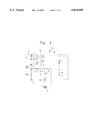
- FIG. 4 is a schematic diagram of a fourth embodiment of the present invention.
- a first switch S1 is adapted to change state when a brake slack adjuster 4 (shown schematically) reaches its end of travel service limit.
- a second switch S2 is embedded within a brake lining 6 (shown schematically) and changes state when the lining wears to its service limit.
- An electronic control unit 8 is electrically connected by a single wire conductor C to switch S1 and serially to switch S2 and to electrical ground G.
- Switch S1 is a normally closed switch which is structurally connected to the brake slack adjuster 4 in some manner such as that disclosed in U.S. Pat. No. 3,776,329 such that when the slack adjuster reaches the out of adjustment range, the switch S1 is opened.
- the conductor C Internal to the control unit 8, the conductor C is connected to a voltage source V through a resistor R.
- the level of the output voltage Vo indicates the condition of the brake system which includes the slack adjuster 4 and the lining 6 and is interpreted by the electronic control unit 8 whereupon the information is transmitted to another part of the vehicle such as the vehicle cab for display to the operator and/or another electronic control unit.
- Switch S1 is a normally closed switch adapted to a brake slack adjuster such that switch S1 is opened when the slack adjuster reaches its service limit. Examples are shown in U.S. Pat. Nos. 3,776,329; 5,253,735 and 5,358,075.
- Switch S2 functions as a normally closed switch which is embedded in the vehicle brake lining 6 such that upon reaching the service limit of the brake lining 6 due to wear, the switch S2 opens from the closed position as shown schematically in FIG. 1. Examples of such brake wear switching systems may be seen by reference to U.S. Pat. Nos. 3,825,891; 3,902,158; 4,204,190 and 5,419,415.
- Switch S2 functions as a normally closed switch which can be a breakable conductive element embedded within the brake lining 6 such that the conductive element is broken by wear of the brake lining 6 at its service limit thereby functioning as a normally closed switch which opens when the brake lining 4 wears to its service limit.
- both switch S1 and switch S2 are closed as shown in FIG. 1.
- Electrical switches S1 and S2 are connected in series between the electronic control unit 8 and chassis ground G by a single wire conductor C as shown in FIG. 1. If switch S1 and switch S2 are closed, then the output voltage Vo is equal to the potential at ground G. If either switch S1 or switch S2 opens due to the slack adjuster 4 and/or the brake lining 6 reaching a service limit, then the output voltage Vo will be equal to the supply voltage V indicating that brake service is required. Also, if a break occurs in the connector C, then the output voltage Vo will go to the supply voltage V thereby indicating a service issue.
- the electronic control unit 8 can be electrically connected to another electronic device to signal the need for service and/or the second electronic control unit can alter truck operation until service can be obtained.
- FIG. 2 a second embodiment of the present invention is shown where switch S1 is connected to ground G and is normally open and switch S2 is normally open where one side of switch S2 is embedded in the brake shoe and makes contact with the brake drum when the brake lining 6 wears to its service limit thereby connecting the conductor C to ground G.
- the output voltage Vo is equal to the supply voltage V.
- switch S1 closes and connects the conductor C to ground G and the output voltage Vo is reduced to the potential at ground G.
- switch S2 is closed by a conductive element embedded in the brake lining 6 which contacts the brake drum thereby connecting the conductor C to ground G and the output voltage Vo is again reduced to the potential at ground G.
- the electronic control unit 8 When the output voltage Vo equals the ground G potential, a signal is generated by the electronic control unit 8 which is transmitted to another electronic module for display in the vehicle cab and/or use for vehicle control and/or readout by an external diagnostic unit and/or airwave transmission to a central control facility.
- both switch S1 and switch S2 are open, then the brake system is in a normal operating condition and the voltage Vo is equal in magnitude to the voltage V as supplied to conductor C through resistor R.
- one side of the switch S2 can be embedded within the brake shoe and the second side of switch S2 can be electrically connected to the brake drum which is at ground G potential. If wear of brake lining 6 has caused switch S2 to close or if the slack adjuster 4 has reached its service limit and switch S1 is closed, then voltage Vo will be at the potential of ground G. Also, in either mode, if the conductor C has been shorted to ground, irrespective of the state of switches S1 and S2, the voltage Vo will be at ground G potential thereby indicating that service is needed to correct the wiring fault and/or service the brake lining 6.
- FIG. 3 a schematic diagram of a third embodiment of the present invention is shown where resistors R1, R2 and R3 have been added along with a current source I to replace the input voltage V shown in FIGS. 1 and 2.
- Resistor R1 is connected in parallel across switch S1 providing for a specific voltage drop when switch S1 is opened depending on the value of resistor R1.
- Resistor R2 is connected in parallel across switch S2 providing for a specific voltage drop when switch S2 is opened depending on the value of resistor R2.
- Resistor R3 is connected in series between switch S2 and resistor R2 and ground G thereby providing for a specific voltage drop depending on the state of switches S1 and S2 and the value of resistors R1, R2 and R3.
- Switches S1 and S2 function as described in reference to FIG. 1.
- Switch S2 can be a conductive loop of wire embedded within the brake lining 6 which is worn open when the brake lining 4 is worn to its service limit.
- both resistors R2 and R3 are connected in series by conductor C to the electronic control unit 8.
- switch S1 opens and resistor R1 is put in service with resistors R2 and R3.
- R1, R2 and R3 must be selected such that the following relationships are satisfied:
- the output voltage Vo measured between the conductor C and ground G depends on the state of the switches S1 and S2 and the conductor C.
- Current source I is a constant current source contained within the electronic control unit 8. The magnitude of the output voltage Vo for selected conditions can be calculated based on the value of the current source I and the resistors R1, R2 and R3 as follows:
- a plurality of capacitors within the electronic control unit 8 are used to determine the proper fault code for the brake condition for transmission externally to the vehicle cab for display to the operator or to other electronic devices.
- FIG. 4 a schematic diagram of a fourth embodiment of the present invention is shown where a plurality of resistors R1, R2 and R3 are connected in series with other circuit elements.
- Switch S1 is normally open and closes when the brake slack adjuster 4 reaches its service limit.
- Switch S2 is normally open and closes when the brake lining 6 wears to its service limit causing a conductive element embedded in the brake lining 6 to contact the brake drum (not shown) thereby connecting resistor R2 to ground G. Examples of similar brake drum contact systems are shown in U.S. Pat. Nos. 2,217,176; 3,297,985; 3,398,246 and 4,387,789 the disclosures of which are incorporated by reference.
- Resistor R1 is connected in series between ground G and switch S1.
- Resistor R2 is connected in series between the conductor C and switch S2 when switch S2 is also connected in series with ground G.
- Resistor R3 is connected in series between resistor R2 and ground G on the conductor C side of resistor R2.
- Current source I is a constant current source contained within the electronic control unit 8.
- the output voltage Vo is measured between the conductor C and ground G and its value indicates the condition of the slack adjuster 4, brake lining 6 and the conductor C according to the following chart:
Abstract
Description
R1≠R2, R1≠R3, R2≠R3 and R1+R2≠R3, R1+R3≠R2 and R2+R3≠R1
______________________________________
Brake System
Condition           Output Voltage Vo
______________________________________
Normal              Vo = IR.sub.3
Slack Adjuster at   Vo = I (R1 + R3)
Service Limit
Brake Lining Worn to
                    Vo = I (R2 + R3)
Service Limit
Slack Adjuster and  Vo = I (R1 + R2 + R3)
Brake Lining at
Service Limit
Conductor open      Vo > I(RI + R2 + R3)
Conductor shorted to Ground
                    Vo reduced by I R3
______________________________________
R1≠R2, R2≠R3, R1≠R3.
______________________________________
Brake System
Condition        Output Voltage Vo
______________________________________
Normal           Vo = IR3
Slack Adjuster at Service Limit
                  ##STR1##
Brake Lining at Service Limit
                  ##STR2##
Slack Adjuster and Brake Lining at Service Limit
                  ##STR3##
Conductor C open Vo > IR where R = largest of R1 or
                 R2 or R3
Conductor C short to ground
                 Vo = 0
______________________________________
Claims (17)
Priority Applications (1)
| Application Number | Priority Date | Filing Date | Title |
|---|---|---|---|
| US08/752,349 US5835009A (en) | 1996-11-19 | 1996-11-19 | Single wire brake condition sensing system |
Applications Claiming Priority (1)
| Application Number | Priority Date | Filing Date | Title |
|---|---|---|---|
| US08/752,349 US5835009A (en) | 1996-11-19 | 1996-11-19 | Single wire brake condition sensing system |
Publications (1)
| Publication Number | Publication Date |
|---|---|
| US5835009A true US5835009A (en) | 1998-11-10 |
Family
ID=25025941
Family Applications (1)
| Application Number | Title | Priority Date | Filing Date |
|---|---|---|---|
| US08/752,349 Expired - Fee Related US5835009A (en) | 1996-11-19 | 1996-11-19 | Single wire brake condition sensing system |
Country Status (1)
| Country | Link |
|---|---|
| US (1) | US5835009A (en) |
Cited By (7)
| Publication number | Priority date | Publication date | Assignee | Title |
|---|---|---|---|---|
| WO2000060250A1 (en) * | 1999-04-01 | 2000-10-12 | Lucas Industries Public Limited Company | Automatic drum brake adjusting device and drum brake comprising same |
| US6366201B1 (en) | 2001-01-23 | 2002-04-02 | Dana Corporation | Parallel resistor array for progressively detecting brake lining wear |
| US20020195298A1 (en) * | 2001-02-08 | 2002-12-26 | Volvo Trucks North America, Inc. | Vehicle diagnostic system |
| US6564909B1 (en) * | 1999-05-14 | 2003-05-20 | I.C.P. S.R.L. | Wear detector for a vehicle braking member |
| US6581728B2 (en) | 2001-02-08 | 2003-06-24 | Volvo Trucks North America, Inc. | Brake shoe proximity sensor |
| US20050109090A1 (en) * | 2002-01-11 | 2005-05-26 | Axel Pfeffer | Brake lining monitoring device and method |
| US20150081159A1 (en) * | 2013-09-17 | 2015-03-19 | Hyundai Motor Company | Apparatus and method of sensing and controlling wear of brake lining |
Citations (25)
| Publication number | Priority date | Publication date | Assignee | Title |
|---|---|---|---|---|
| US1957051A (en) * | 1930-09-24 | 1934-05-01 | Bendix Brake Co | Brake temperature indicator |
| US2217176A (en) * | 1938-08-15 | 1940-10-08 | Walter W Madison | Brake wear indicating apparatus |
| US3297985A (en) * | 1964-04-14 | 1967-01-10 | John R Trebonsky | Brake lining wear indicating means |
| US3398246A (en) * | 1966-06-29 | 1968-08-20 | Linet William | Brake wear alert device |
| US3553643A (en) * | 1968-09-04 | 1971-01-05 | Edward M Maras | Brake lining wear indicator |
| US3674114A (en) * | 1970-09-11 | 1972-07-04 | Bendix Corp | Brake lining temperature probe |
| US3755774A (en) * | 1970-12-22 | 1973-08-28 | Jurid Werke Gmbh | Axle identifying brake warning system |
| US3776329A (en) * | 1971-03-19 | 1973-12-04 | Self Energizing Disc Brakes Lt | Brake wear and adjustment device |
| US3825891A (en) * | 1971-01-16 | 1974-07-23 | Daimler Benz Ag | Brake-lining wear-indicator |
| US3902158A (en) * | 1973-04-28 | 1975-08-26 | Sab Brake Regulator Co Ltd | Electrical device for detecting or indicating vehicle brake lining wear |
| US4004269A (en) * | 1973-07-28 | 1977-01-18 | Nippondenso Co., Ltd. | Brake lining wear warning system |
| US4204190A (en) * | 1977-12-07 | 1980-05-20 | Lucas Industries Limited | Brake pad wear detection system |
| US4387789A (en) * | 1976-07-21 | 1983-06-14 | Rockwell International Corporation | Electrical brake lining wear indicator |
| US4562421A (en) * | 1983-01-31 | 1985-12-31 | Duffy Dennis A | Brake wear sensor |
| US4646001A (en) * | 1983-11-21 | 1987-02-24 | Morganite Electrical Carbon Limited | Resistive wear sensors |
| US4800991A (en) * | 1985-08-19 | 1989-01-31 | Miller Nicholas A | Brake maintenance monitor |
| US4824260A (en) * | 1988-04-13 | 1989-04-25 | Abex Corporation | Brake block temperature and wear measuring device |
| US5253735A (en) * | 1992-09-28 | 1993-10-19 | Larson Reese G | Apparatus to sense and annunciate truck brake condition |
| US5285190A (en) * | 1991-11-04 | 1994-02-08 | Onboard Systems Limited | Automatic slack adjuster with operation and adjustment monitor |
| US5302940A (en) * | 1992-10-05 | 1994-04-12 | Chen Chi Shan | Motor vehicle brake detector |
| US5339069A (en) * | 1992-07-01 | 1994-08-16 | Tripen Enterprises Ltd. | Brake monitoring system |
| US5347858A (en) * | 1991-12-12 | 1994-09-20 | Sumitomo Wiring Systems, Ltd. | Wear-detection probe for a brake lining material |
| US5358075A (en) * | 1993-06-25 | 1994-10-25 | Jarzombek Richard J | Brake movement and adjustment monitoring device |
| US5419415A (en) * | 1992-12-21 | 1995-05-30 | Inventio Ag | Apparatus for monitoring elevator brakes |
| US5450930A (en) * | 1993-12-09 | 1995-09-19 | Mgm Brakes | Heavy duty electronic brake stroke indicator |
-
1996
- 1996-11-19 US US08/752,349 patent/US5835009A/en not_active Expired - Fee Related
Patent Citations (25)
| Publication number | Priority date | Publication date | Assignee | Title |
|---|---|---|---|---|
| US1957051A (en) * | 1930-09-24 | 1934-05-01 | Bendix Brake Co | Brake temperature indicator |
| US2217176A (en) * | 1938-08-15 | 1940-10-08 | Walter W Madison | Brake wear indicating apparatus |
| US3297985A (en) * | 1964-04-14 | 1967-01-10 | John R Trebonsky | Brake lining wear indicating means |
| US3398246A (en) * | 1966-06-29 | 1968-08-20 | Linet William | Brake wear alert device |
| US3553643A (en) * | 1968-09-04 | 1971-01-05 | Edward M Maras | Brake lining wear indicator |
| US3674114A (en) * | 1970-09-11 | 1972-07-04 | Bendix Corp | Brake lining temperature probe |
| US3755774A (en) * | 1970-12-22 | 1973-08-28 | Jurid Werke Gmbh | Axle identifying brake warning system |
| US3825891A (en) * | 1971-01-16 | 1974-07-23 | Daimler Benz Ag | Brake-lining wear-indicator |
| US3776329A (en) * | 1971-03-19 | 1973-12-04 | Self Energizing Disc Brakes Lt | Brake wear and adjustment device |
| US3902158A (en) * | 1973-04-28 | 1975-08-26 | Sab Brake Regulator Co Ltd | Electrical device for detecting or indicating vehicle brake lining wear |
| US4004269A (en) * | 1973-07-28 | 1977-01-18 | Nippondenso Co., Ltd. | Brake lining wear warning system |
| US4387789A (en) * | 1976-07-21 | 1983-06-14 | Rockwell International Corporation | Electrical brake lining wear indicator |
| US4204190A (en) * | 1977-12-07 | 1980-05-20 | Lucas Industries Limited | Brake pad wear detection system |
| US4562421A (en) * | 1983-01-31 | 1985-12-31 | Duffy Dennis A | Brake wear sensor |
| US4646001A (en) * | 1983-11-21 | 1987-02-24 | Morganite Electrical Carbon Limited | Resistive wear sensors |
| US4800991A (en) * | 1985-08-19 | 1989-01-31 | Miller Nicholas A | Brake maintenance monitor |
| US4824260A (en) * | 1988-04-13 | 1989-04-25 | Abex Corporation | Brake block temperature and wear measuring device |
| US5285190A (en) * | 1991-11-04 | 1994-02-08 | Onboard Systems Limited | Automatic slack adjuster with operation and adjustment monitor |
| US5347858A (en) * | 1991-12-12 | 1994-09-20 | Sumitomo Wiring Systems, Ltd. | Wear-detection probe for a brake lining material |
| US5339069A (en) * | 1992-07-01 | 1994-08-16 | Tripen Enterprises Ltd. | Brake monitoring system |
| US5253735A (en) * | 1992-09-28 | 1993-10-19 | Larson Reese G | Apparatus to sense and annunciate truck brake condition |
| US5302940A (en) * | 1992-10-05 | 1994-04-12 | Chen Chi Shan | Motor vehicle brake detector |
| US5419415A (en) * | 1992-12-21 | 1995-05-30 | Inventio Ag | Apparatus for monitoring elevator brakes |
| US5358075A (en) * | 1993-06-25 | 1994-10-25 | Jarzombek Richard J | Brake movement and adjustment monitoring device |
| US5450930A (en) * | 1993-12-09 | 1995-09-19 | Mgm Brakes | Heavy duty electronic brake stroke indicator |
Cited By (10)
| Publication number | Priority date | Publication date | Assignee | Title |
|---|---|---|---|---|
| WO2000060250A1 (en) * | 1999-04-01 | 2000-10-12 | Lucas Industries Public Limited Company | Automatic drum brake adjusting device and drum brake comprising same |
| US6564909B1 (en) * | 1999-05-14 | 2003-05-20 | I.C.P. S.R.L. | Wear detector for a vehicle braking member |
| US6366201B1 (en) | 2001-01-23 | 2002-04-02 | Dana Corporation | Parallel resistor array for progressively detecting brake lining wear |
| US20020195298A1 (en) * | 2001-02-08 | 2002-12-26 | Volvo Trucks North America, Inc. | Vehicle diagnostic system |
| US6581728B2 (en) | 2001-02-08 | 2003-06-24 | Volvo Trucks North America, Inc. | Brake shoe proximity sensor |
| US6680672B2 (en) | 2001-02-08 | 2004-01-20 | Volvo Trucks North America, Inc. | Vehicle diagnostic system |
| US7114596B2 (en) | 2001-02-08 | 2006-10-03 | Volvo Trucks North America, Inc. | Brake shoe proximity sensor |
| US20050109090A1 (en) * | 2002-01-11 | 2005-05-26 | Axel Pfeffer | Brake lining monitoring device and method |
| US7328607B2 (en) * | 2002-01-11 | 2008-02-12 | Otis Elevator Company | Brake lining monitoring device and method |
| US20150081159A1 (en) * | 2013-09-17 | 2015-03-19 | Hyundai Motor Company | Apparatus and method of sensing and controlling wear of brake lining |
Similar Documents
| Publication | Publication Date | Title |
|---|---|---|
| US6360850B1 (en) | Progressive brake lining wear sensor | |
| EP0768474A2 (en) | Vehicle friction material condition measurement system | |
| EP0719417B1 (en) | Field transmitter built-in test equipment | |
| US3975708A (en) | Vehicle condition monitoring system | |
| US5637794A (en) | Resistive brake lining wear and temperature sensing system | |
| US5632359A (en) | Disk brake with stroke indicator | |
| US6064928A (en) | Mechanical sensor diagnostic method and system | |
| US6477893B1 (en) | Erodable sensor for progressive brake wear detection | |
| US6366201B1 (en) | Parallel resistor array for progressively detecting brake lining wear | |
| US6424143B1 (en) | Process for monitoring the function of a sensor module and a sensor module to perform the process | |
| WO2010119532A1 (en) | Abnormality detection device for detection circuits and electric circuits, and detection system and electronic system using the abnormality detection device | |
| WO1995016149A1 (en) | Heavy duty electronic brake stroke indicator | |
| US5309314A (en) | Circuit configuration for actuating a safety relay | |
| US5835009A (en) | Single wire brake condition sensing system | |
| US20060149427A1 (en) | Apparatus for monitoring a supply system, in particular a motor-vehicle electrical system, and method for monitoring a supply system for this type | |
| CA2286514C (en) | Improvements relating to monitoring apparatus for electrical circuits | |
| JPH085365B2 (en) | Normal function monitoring device of switch connected to resistance network for checking tightness of safety belt buckle in automobile | |
| JPH0858556A (en) | Electronic control device for automotive use and method of protecting said device | |
| US4459595A (en) | Condition responsive RF transmitting device | |
| US4604613A (en) | Status-indicating current interrupter | |
| US7443075B2 (en) | Entrapment detecting system | |
| FI102322B (en) | Differential pressure monitor | |
| US4668946A (en) | System for detecting the failure of a filament lamp | |
| US7265955B2 (en) | Protective circuit for analog sensors | |
| KR100201024B1 (en) | Thermistor circuit monitoring apparatus |
Legal Events
| Date | Code | Title | Description |
|---|---|---|---|
| AS | Assignment |
Owner name: EATON CORPORATION, OHIO Free format text: ASSIGNMENT OF ASSIGNORS INTEREST;ASSIGNOR:HANISKO, JOHN-CYRIL P.;REEL/FRAME:008314/0523 Effective date: 19961118 |
|
| AS | Assignment |
Owner name: SANFORD ACQUISITION COMPANY, MICHIGAN Free format text: ASSIGNMENT OF ASSIGNORS INTEREST;ASSIGNOR:EATON CORPORATION;REEL/FRAME:008996/0976 Effective date: 19980101 |
|
| AS | Assignment |
Owner name: SANFORD ACQUISITION COMPANY, MICHIGAN Free format text: ASSIGNMENT OF ASSIGNORS INTEREST;ASSIGNOR:EATON CORPORATION;REEL/FRAME:009645/0581 Effective date: 19980101 |
|
| FEPP | Fee payment procedure |
Free format text: PAYOR NUMBER ASSIGNED (ORIGINAL EVENT CODE: ASPN); ENTITY STATUS OF PATENT OWNER: LARGE ENTITY |
|
| FPAY | Fee payment |
Year of fee payment: 4 |
|
| REMI | Maintenance fee reminder mailed | ||
| AS | Assignment |
Owner name: DANA TECHNOLOGY INC., MICHIGAN Free format text: CHANGE OF NAME;ASSIGNOR:SANFORD ACQUISITION COMPANY;REEL/FRAME:017230/0622 Effective date: 19991201 |
|
| FPAY | Fee payment |
Year of fee payment: 8 |
|
| AS | Assignment |
Owner name: DANA HEAVY VEHICLE SYSTEMS GROUP, LLC, OHIO Free format text: ASSIGNMENT OF ASSIGNORS INTEREST;ASSIGNOR:DANA TECHNOLOGY INC.;REEL/FRAME:020550/0454 Effective date: 20080131 |
|
| AS | Assignment |
Owner name: CITICORP USA, INC., NEW YORK Free format text: INTELLECTUAL PROPERTY TERM FACILITY SECURITY AGREEMENT;ASSIGNORS:DANA HOLDING CORPORATION;DANA LIMITED;DANA AUTOMOTIVE SYSTEMS GROUP, LLC;AND OTHERS;REEL/FRAME:020859/0359 Effective date: 20080131 Owner name: CITICORP USA, INC., NEW YORK Free format text: INTELLECTUAL PROPERTY REVOLVING FACILITY SECURITY AGREEMENT;ASSIGNORS:DANA HOLDING CORPORATION;DANA LIMITED;DANA AUTOMOTIVE SYSTEMS GROUP, LLC;AND OTHERS;REEL/FRAME:020859/0249 Effective date: 20080131 Owner name: CITICORP USA, INC.,NEW YORK Free format text: INTELLECTUAL PROPERTY REVOLVING FACILITY SECURITY AGREEMENT;ASSIGNORS:DANA HOLDING CORPORATION;DANA LIMITED;DANA AUTOMOTIVE SYSTEMS GROUP, LLC;AND OTHERS;REEL/FRAME:020859/0249 Effective date: 20080131 Owner name: CITICORP USA, INC.,NEW YORK Free format text: INTELLECTUAL PROPERTY TERM FACILITY SECURITY AGREEMENT;ASSIGNORS:DANA HOLDING CORPORATION;DANA LIMITED;DANA AUTOMOTIVE SYSTEMS GROUP, LLC;AND OTHERS;REEL/FRAME:020859/0359 Effective date: 20080131 |
|
| REMI | Maintenance fee reminder mailed | ||
| LAPS | Lapse for failure to pay maintenance fees | ||
| STCH | Information on status: patent discontinuation |
Free format text: PATENT EXPIRED DUE TO NONPAYMENT OF MAINTENANCE FEES UNDER 37 CFR 1.362 |
|
| FP | Lapsed due to failure to pay maintenance fee |
Effective date: 20101110 |