US5828142A - Platen for use with lithographic stages and method of making same - Google Patents
Platen for use with lithographic stages and method of making same Download PDFInfo
- Publication number
- US5828142A US5828142A US08/918,704 US91870497A US5828142A US 5828142 A US5828142 A US 5828142A US 91870497 A US91870497 A US 91870497A US 5828142 A US5828142 A US 5828142A
- Authority
- US
- United States
- Prior art keywords
- platen
- tiles
- teeth
- magnetic material
- powdered
- Prior art date
- Legal status (The legal status is an assumption and is not a legal conclusion. Google has not performed a legal analysis and makes no representation as to the accuracy of the status listed.)
- Expired - Lifetime
Links
Images


Classifications
-
- G—PHYSICS
- G03—PHOTOGRAPHY; CINEMATOGRAPHY; ANALOGOUS TECHNIQUES USING WAVES OTHER THAN OPTICAL WAVES; ELECTROGRAPHY; HOLOGRAPHY
- G03F—PHOTOMECHANICAL PRODUCTION OF TEXTURED OR PATTERNED SURFACES, e.g. FOR PRINTING, FOR PROCESSING OF SEMICONDUCTOR DEVICES; MATERIALS THEREFOR; ORIGINALS THEREFOR; APPARATUS SPECIALLY ADAPTED THEREFOR
- G03F7/00—Photomechanical, e.g. photolithographic, production of textured or patterned surfaces, e.g. printing surfaces; Materials therefor, e.g. comprising photoresists; Apparatus specially adapted therefor
- G03F7/70—Microphotolithographic exposure; Apparatus therefor
- G03F7/70691—Handling of masks or workpieces
- G03F7/70758—Drive means, e.g. actuators, motors for long- or short-stroke modules or fine or coarse driving
-
- H—ELECTRICITY
- H02—GENERATION; CONVERSION OR DISTRIBUTION OF ELECTRIC POWER
- H02K—DYNAMO-ELECTRIC MACHINES
- H02K1/00—Details of the magnetic circuit
- H02K1/02—Details of the magnetic circuit characterised by the magnetic material
-
- H—ELECTRICITY
- H02—GENERATION; CONVERSION OR DISTRIBUTION OF ELECTRIC POWER
- H02K—DYNAMO-ELECTRIC MACHINES
- H02K1/00—Details of the magnetic circuit
- H02K1/06—Details of the magnetic circuit characterised by the shape, form or construction
-
- H—ELECTRICITY
- H02—GENERATION; CONVERSION OR DISTRIBUTION OF ELECTRIC POWER
- H02K—DYNAMO-ELECTRIC MACHINES
- H02K15/00—Methods or apparatus specially adapted for manufacturing, assembling, maintaining or repairing of dynamo-electric machines
- H02K15/02—Methods or apparatus specially adapted for manufacturing, assembling, maintaining or repairing of dynamo-electric machines of stator or rotor bodies
-
- H—ELECTRICITY
- H02—GENERATION; CONVERSION OR DISTRIBUTION OF ELECTRIC POWER
- H02K—DYNAMO-ELECTRIC MACHINES
- H02K41/00—Propulsion systems in which a rigid body is moved along a path due to dynamo-electric interaction between the body and a magnetic field travelling along the path
- H02K41/02—Linear motors; Sectional motors
- H02K41/03—Synchronous motors; Motors moving step by step; Reluctance motors
-
- H—ELECTRICITY
- H02—GENERATION; CONVERSION OR DISTRIBUTION OF ELECTRIC POWER
- H02K—DYNAMO-ELECTRIC MACHINES
- H02K2201/00—Specific aspects not provided for in the other groups of this subclass relating to the magnetic circuits
- H02K2201/18—Machines moving with multiple degrees of freedom
-
- Y—GENERAL TAGGING OF NEW TECHNOLOGICAL DEVELOPMENTS; GENERAL TAGGING OF CROSS-SECTIONAL TECHNOLOGIES SPANNING OVER SEVERAL SECTIONS OF THE IPC; TECHNICAL SUBJECTS COVERED BY FORMER USPC CROSS-REFERENCE ART COLLECTIONS [XRACs] AND DIGESTS
- Y10—TECHNICAL SUBJECTS COVERED BY FORMER USPC
- Y10T—TECHNICAL SUBJECTS COVERED BY FORMER US CLASSIFICATION
- Y10T29/00—Metal working
- Y10T29/49—Method of mechanical manufacture
- Y10T29/49002—Electrical device making
- Y10T29/49009—Dynamoelectric machine
Definitions
- This invention relates to a platen usable with a lithographic stage, a platen which will permit rapid and accurate positioning of the stage, i.e., a platen usable, for example, with Sawyer type motors (linear stepping motors).
- LAED's large area electronic devices
- lithographic technology involves the multiple projection of reticle images upon photoresist coated substrates. This, in turn, requires the projection of "stitched" multiple images upon each of the layers, so that the entire substrate area can be covered. A positioning accuracy of at least 0.2 ⁇ m is necessary. Thus, it is highly important that the stage carrying the substrate be capable of precise movement; and, for efficiency, it is also important that this movement be rapidly accomplished.
- the present invention uses linear stepping motors and a unique platen; and it achieves precise positioning by use of sensing means related to the platen.
- linear stepping motors have used soft iron in the platen with a tooth pitch of about 1. mm..
- the platen is chemically etched to produce the approximately 0.5 mm square teeth.
- the use of soft iron with its low resistivity, however, causes large eddy current losses. Fabrication of coarse pitch units has been a problem because soft iron is difficult and expensive to machine, and the teeth cannot be chemically etched to the required tolerance. Also the eddy current losses would still exist.
- the present invention solves these problems by using powdered metal technology, whereby small tiles are pressed and then formed into a large platen of any practical size. An insulated powder is used so the eddy currents are reduced significantly.
- This invention relates to the field of lithography, and has the usual optical systems for projecting reticle images upon a substrate. It includes a stage, with a supporting platen, and uses linear motors associated with the stage to adjust the position of the stage in both x-, y-, and ⁇ -directions.
- the platen consists of an array of grid tiles each having a multiplicity of precisely placed magnetic teeth running in orthogonal directions. The tiles have been formed through powder metallurgy techniques, using a coated powdered metal so as to increase resistance and decrease eddy currents.
- the space between the teeth has been filled with a non-magnetic and relatively non-conducting material such as filled epoxy resin where the filler is Aluminum oxide (Al 2 O 3 ) for instance; and the upper surface of the platen has been ground or lapped flat so that it is planar and smooth.
- the linear motors, acting in conjunction with the teeth can move the stage the desired amounts in the desired directions over the surface of the platen.
- FIG. 1 is a generalized elevation showing the layout of a lithographic projection system.
- FIG. 2 is a plan view of the stage and platen of the type used in my invention.
- FIG. 3 is a vertical section through a portion of the platen and a portion of the stage, showing the positioning of the sensors with respect to the teeth.
- FIG. 4 is a simplified circuit diagram showing the system of current measurement used to determine the capacitances of the various sensor plates from position to position.
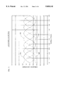
- FIG. 5 is an idealized graph showing the relative capacitances of each of the four sensor plates for different positions relative to the teeth in the platen. Knowing the ratios and magnitudes of these capacitances, the position within any pitch can be determined.
- FIG. 6 is a graph showing the calculated ratios of the capacitances, for determining which correction table is to be used.
- FIG. 7 is a flow chart used to determine position and pitch error, so that the platen position can be adjusted for most accurate placement.
- FIG. 8 is a perspective view of the tile, showing its teeth, but before application of filler epoxy.
- FIG. 9 is a perspective view of the platen, after filler epoxy has been applied.
- FIG. 10 is a perspective view of a section of platen, formed of many separate grid tiles, all mounted on the same base.
- FIG. 1 shows the type of lithographic projection system which could be used with the present invention. It includes a light source 1, projecting light through reticle holder 3, with reticle 5, through projection lens 7. The resulting image is formed on the upper surface of substrate 15 on movable stage 11, carried by platen 13.
- Platen 13 has an upper surface 16 formed of a series of aligned and equally spaced ferromagnetic teeth 17 with non-magnetic material, such as epoxy filler 18, in between, ground to provide a smooth, planar upper surface 16 (See also FIGS. 3 and 8 to 10).
- the teeth are arranged in rows, running in the x-direction (horizontal in FIG. 2) and columns running in the y-direction (vertical in FIG. 2).
- the teeth are square, of uniform width and length, and are spaced from one another an equal distance. They are preferably 2.5 mm on a side, spaced 2.5 mm from one another, and 1 mm high.
- the platen is formed from an array of small tiles typically 50 mm on a side, each containing 100 2.5 mm ⁇ 2.5 mm teeth arranged on 5 mm centers.
- the tiles are preferably formed by powder metallurgy (under heat and pressure) from soft iron particles measuring about 80 to 160 microns across (80 to 40 mesh).
- the powder is currently pure iron, similar to CARPENTER ELECTRICAL IRON, but the iron may also contain small amounts of Silicon (1 to 3 wt %) to reduce hysteresis loss.
- the iron powder used would be coated with an insulating material, such as LEXAN or polycarbonate, but may also be insulated with a glass or ceramic material .
- the tiles are formed at about 550° F. at a pressure of between 45 and 55 tons per square inch. The tiles may be subsequently heat treated to improve the mechanical and magnetic properties.
- the size of the teeth and their spacing should be the same, though, if desired, sizing and spacing can be different in the x-direction from that in the y-direction.
- the space between the teeth is filled with filled epoxy resin, and the resulting upper surface is ground and/or lapped to produce a planar upper surface flat to at least within about 2 ⁇ m per 200 mm by 200 mm square surface area.
- the teeth are shown, prior to the addition of the epoxy resin, in FIG. 8; and, after the addition of the resin, in FIG. 9.
- the platen is formed from an array of tiles.
- twenty four tiles 13 can be secured to a granite base 14 by adhesive 20 , creating a 300 mm ⁇ 200 mm platen.
- the twenty four tiles should be aligned such that their teeth form one continuous flat surface; and the tiles positioned relative to one another such that the spacing of the teeth between tiles is the same as the spacing of the teeth on a single tile.
- Stage 11 is supported above platen 13 on air bearings of the customary type.
- the air gap 43 (FIG. 3) between the sensor plates 45A-D and the teeth 17 of the platen can be any reasonable distance required, but I have found a distance of about 13 ⁇ m satisfactory.
- the movable stage 11 carries four linear motors, two for movement of the stage in the x-direction, motors 19 and 21; and two for movement of the stage in the y-direction, motors 23 and 25. Pairs of x-motors, or y-motors, or both are used to control motion in the theta direction, i.e., rotation. Motors 19 and 21 are at a 90 degree angle to motors 23 and 25. Motors 19 and 21 work in conjunction with rows of teeth running in the y-direction; and motors 23 and 25 work in conjunction with rows of teeth running in the x-direction.
- the platen 13 can be considerably larger than the stage 11, permitting a large, but precise, range of movement of the stage over the platen.
- Position sensors 31 and 33 are positioned within the y-direction linear motors 23 and 25; and position sensors 35 and 37 are positioned within the x-direction linear motors 19 and 21.
- the sensors serve to determine the exact position in the x- and y-direction (and degree of rotation) of the stage with respect to the platen 13. This information is then used in association with a computer to drive the linear motors, causing the movable stage to be located in exactly the position desired.
- FIG. 3 is a vertical section showing the relationship of one sensor 31 with respect to the teeth 17 on the platen; the other sensors 33, 35, and 37 are similar.
- Each sensor carries four sensor plates 45A, 45B, 45C, and 45D on a PC board 42.
- Each sensor plate should have the same width dimensions as the teeth, which, in the given example, is 2.5 mm.
- the length should be an integral multiple of the pitch length which in this case is 80 mm.
- the sensor plates are paired, and alternate in position. Thus, plates 45A and 45B are one pair; and plates 45C and 45D are another pair, with plate 45C between plates 45A and 45B, and plate 45B between plates 45C and 45D.
- a metal shield layer 47 is positioned above the sensors on the PC board, and, in addition, shield plate 49 surrounds the row of plates 45A-D and is connected to shield layer 47.
- the shield layer 47 and shield plates 49 are driven by the same voltage as are the sensor plates 45A-D.
- the shield plates also serve to focus the field from the sensor plates to the teeth on the platen.
- a grounded ground plate 51 is carried by the PC board above shield layer 47.
- Measurement of the capacitances between each of sensor plates 45A-D and the teeth is required. This measurement is based upon the principle that, for a given frequency, the current flow through a capacitor is proportional to the capacitance. A schematic drawing of the wiring necessary to measure these capacitances is shown in FIG. 4. Metal platen 13 is grounded, so its teeth 17 form the second plate of capacitors with each of the plates 45A-D. Their capacitance will vary with the position of each of the plates relative to the teeth. Sensor plates 45A, 45B, 45C, and 45D each in series with their respective ammeters 55A, 55B, 55C, and 55D, and these are connected to a sine wave power source 53, preferably having a frequency in the range between 1 to 5 megaHz.
- Outputs from the ammeters are on lines 56A, 56B, 56C, and 56D, respectively.
- the output from the first pair of sensor plates 45A and 45B are on lines 56A and 56B; and the outputs from the second pair of sensor plates 45C and 45D are on lines 56C and 56D.
- I refer to the output from the first pair as "Phase A,” and from the second as “Phase B.” These outputs will vary depending upon the position of the respective sensor plates relative to the teeth; and, therefore, this output, when properly interpreted, serves to identify the specific position of the stage relative to the platen.
- FIG. 5 is a graph showing how the relative capacitances measured for each of the sensor plates would vary ideally with position.
- the abscissa indicates the position of the plates relative to the teeth on the platen; and the ordinate shows the relative measured capacitance.
- the plate is directly over a tooth (such as position 1 in the abscissa for sensor plate 45D; see FIG. 4); its relative capacitance is at a maximum (about 1.35); and when it is directly over the epoxy space or void between teeth (again, using position 1), such as sensor plate 45C, its relative capacity is at a minimum (about 0.625).
- sensor plate 45A will be directly over a tooth at position pitches of about 0.25 and 1.25; sensor plate 45B will be directly over a tooth at position pitches of about 0.75 and 1.75; and similarly for the other sensor plates.
- measured capacitance is indicative of sensor position, which means that the position of the platen in the x-, y-, and ⁇ -directions can be determined by determining relative capacitances.
- first pair and second pair I refer to sensor plates 45A and 45B, and sensor plates 45C and 45D, respectively).
- Phase A the readings from ammeters 55A and 55B, on lines 56A and 56B, are subtracted from each other to give a net reading
- Phase B the readings from ammeters 55C and 55D, on lines 56C and 56D, are subtracted from each other to give a net reading.
- phase size and phase ratios There are four possible combinations of phase size and phase ratios. These are:
- Phase A/B A>B and A ⁇ B;
- Phase B/A A>B and A ⁇ B.
- Table 0 is used for Phase A/B and A ⁇ B
- Table 1 is used for Phase B/A and A>B
- Table 2 is used for Phase A/B and A ⁇ B
- Table 3 is used for Phase B/A and A>B
- the position within any pitch can be determined. This is shown in FIG. 6, where curves of the Phase ratios are plotted against A ⁇ B and A>B; and the selection of tables and the points used in the tables are determined from the curves shown. The position determined then equals the fraction of the current pitch times the current pitch length plus the sum of all previous pitch lengths.
- This procedure is used separately for each of the position sensors used, and the result of all these calculations provides a computer with the stage's position in x, y and ⁇ (theta). The computer can then provide the necessary signals to the linear motors to position the stage as desired.
- FIG. 7 is a flow chart showing the computer steps used in these calculations.
- the analog signals of Phase A and Phase B (from FIG. 4) are fed to an analog to digital converter 71 where they are converted to digital signals with enough accuracy for the required positional resolution.
- These digital signals are processed in the computer according to block diagram FIG. 7. Signals are then sent to the linear motors 19, 21, 23, and 25, as required, for correct positioning of the stage.
Abstract
Description
Claims (25)
Priority Applications (1)
| Application Number | Priority Date | Filing Date | Title |
|---|---|---|---|
| US08/918,704 US5828142A (en) | 1994-10-03 | 1997-08-22 | Platen for use with lithographic stages and method of making same |
Applications Claiming Priority (3)
| Application Number | Priority Date | Filing Date | Title |
|---|---|---|---|
| US31673994A | 1994-10-03 | 1994-10-03 | |
| US56039395A | 1995-11-17 | 1995-11-17 | |
| US08/918,704 US5828142A (en) | 1994-10-03 | 1997-08-22 | Platen for use with lithographic stages and method of making same |
Related Parent Applications (1)
| Application Number | Title | Priority Date | Filing Date |
|---|---|---|---|
| US56039395A Continuation | 1994-10-03 | 1995-11-17 |
Publications (1)
| Publication Number | Publication Date |
|---|---|
| US5828142A true US5828142A (en) | 1998-10-27 |
Family
ID=26980567
Family Applications (1)
| Application Number | Title | Priority Date | Filing Date |
|---|---|---|---|
| US08/918,704 Expired - Lifetime US5828142A (en) | 1994-10-03 | 1997-08-22 | Platen for use with lithographic stages and method of making same |
Country Status (1)
| Country | Link |
|---|---|
| US (1) | US5828142A (en) |
Cited By (32)
| Publication number | Priority date | Publication date | Assignee | Title |
|---|---|---|---|---|
| US6016021A (en) * | 1998-02-20 | 2000-01-18 | Northern Magnetics, Inc. | Linear stepper motor |
| US6175169B1 (en) | 1999-05-03 | 2001-01-16 | Ralph L. Hollis, Jr. | Closed-loop planar linear motor with integral monolithic three-degree-of-freedom AC-magnetic position/orientation sensor |
| US6188150B1 (en) | 1999-06-16 | 2001-02-13 | Euv, Llc | Light weight high-stiffness stage platen |
| US6320649B1 (en) * | 1998-02-04 | 2001-11-20 | Canon Kabushiki Kaisha | Stage system for exposure apparatus |
| US6545375B2 (en) | 2001-02-20 | 2003-04-08 | Ralph L. Hollis, Jr. | Field-joinable platen tiles for planar motors |
| US20040080735A1 (en) * | 2002-10-18 | 2004-04-29 | Yoneta Tanaka | Plain surface stage apparatus |
| US20040155534A1 (en) * | 2003-02-07 | 2004-08-12 | Engwall Mats Anders | Structure integrating gas support bearing and a planar electromagnetic drive and levitation system |
| US6784572B1 (en) | 1991-03-17 | 2004-08-31 | Anorad Corporation | Path arrangement for a multi-track linear motor system and method to control same |
| US6876105B1 (en) * | 1998-02-26 | 2005-04-05 | Anorad Corporation | Wireless encoder |
| US6963148B1 (en) | 1998-02-26 | 2005-11-08 | Anorad Corporation | Wireless encoder |
| US20050264777A1 (en) * | 2004-05-28 | 2005-12-01 | Azores Corporation | High speed lithography machine and method |
| DE102004045303A1 (en) * | 2004-09-18 | 2006-04-06 | Pasim Direktantriebe Gmbh | Air bearing planar direct drive for linear direct current motor, has pole teeth on prismatic cut stator and rotor in tooth pitch period, which ranges between certain millimeters, where period is sum of tooth width and tooth base width |
| WO2006108855A1 (en) * | 2005-04-15 | 2006-10-19 | Siemens Aktiengesellschaft | Synchronous linear motor with remote scanning of the tooth structure of the secondary part |
| WO2006108847A1 (en) * | 2005-04-15 | 2006-10-19 | Siemens Aktiengesellschaft | Goods conveying system comprising a synchronous linear motor |
| US20070024155A1 (en) * | 2005-07-26 | 2007-02-01 | Calvet Robert J | MEMS digital linear actuator |
| US7262523B1 (en) | 1998-02-26 | 2007-08-28 | Anorad Corporation | Wireless encoder |
| EP2051141A1 (en) | 2007-10-17 | 2009-04-22 | Canon Kabushiki Kaisha | Driving apparatus and exposure apparatus, and device fabrication method |
| US7548303B2 (en) | 2004-09-04 | 2009-06-16 | Nikon Corporation | Cooling assembly for a stage |
| NL2003128C2 (en) * | 2009-07-03 | 2011-01-04 | Tecnotion B V | A method for fabricating an electromagnetic actuator, an electromagnetic actuator, and a charged particle device comprising the same. |
| DE102009056854A1 (en) * | 2009-12-03 | 2011-06-09 | Festo Ag & Co. Kg | Toothed rod for linear direct drive, has tooth tracing tooth space, which is filled with filling to form closed surface with tooth, where filling is formed of filler material by plastic deformation in tooth gap |
| US20120280579A1 (en) * | 2011-05-06 | 2012-11-08 | Bose Corporation | Linear moving magnet motor cogging force ripple reducing |
| US20130033125A1 (en) * | 2011-08-03 | 2013-02-07 | Kabushiki Kaisha Yaskawa Denki | Linear motor armature and linear motor |
| TWI393207B (en) * | 2007-10-17 | 2013-04-11 | Canon Kk | Driving apparatus and exposure apparatus, and device fabrication method |
| WO2014055335A1 (en) | 2012-10-05 | 2014-04-10 | Rudolph Technologies, Inc. | Planar motor system with increased efficiency |
| US20150326150A1 (en) * | 2012-12-12 | 2015-11-12 | Tsinghua University | Maglev workpiece table with six degrees of freedom |
| US9346371B2 (en) | 2009-01-23 | 2016-05-24 | Magnemotion, Inc. | Transport system powered by short block linear synchronous motors |
| US9771000B2 (en) | 2009-01-23 | 2017-09-26 | Magnemotion, Inc. | Short block linear synchronous motors and switching mechanisms |
| US9802507B2 (en) | 2013-09-21 | 2017-10-31 | Magnemotion, Inc. | Linear motor transport for packaging and other uses |
| WO2019067221A2 (en) | 2017-09-29 | 2019-04-04 | Rudolph Technologies, Inc. | High resolution stage positioner |
| WO2019067809A2 (en) | 2017-09-29 | 2019-04-04 | Rudolph Technologies, Inc. | System and method for optimizing a lithography exposure process |
| WO2019133457A1 (en) | 2017-12-28 | 2019-07-04 | Rudolph Technologies, Inc. | Conformal stage |
| US11687010B2 (en) | 2020-02-21 | 2023-06-27 | Onto Innovation Inc. | System and method for correcting overlay errors in a lithographic process |
Citations (34)
| Publication number | Priority date | Publication date | Assignee | Title |
|---|---|---|---|---|
| US3478877A (en) * | 1967-08-04 | 1969-11-18 | Ok Partnership Ltd | Article selection system |
| US3610413A (en) * | 1969-06-16 | 1971-10-05 | Ok Partnership Ltd | Magnetically responsive card retrieval system |
| US3656014A (en) * | 1971-04-08 | 1972-04-11 | Gerber Scientific Instr Co | Damping apparatus for a linear step motor having two translational degrees of freedom |
| USRE27436E (en) * | 1966-05-31 | 1972-07-18 | Magnetic positioning device | |
| US3695760A (en) * | 1970-08-17 | 1972-10-03 | Renton Eng Co | Photolithographical image processing apparatus |
| US3889165A (en) * | 1971-09-28 | 1975-06-10 | Telemecanique Electrique | Linear and rotary actuator |
| US4015154A (en) * | 1974-12-23 | 1977-03-29 | Sony Corporation | Motor and method for making same |
| US4158580A (en) * | 1978-04-14 | 1979-06-19 | Westinghouse Electric Corp. | Method of making pressed magnetic core components |
| US4218507A (en) * | 1975-01-13 | 1980-08-19 | Graham Magnetics, Inc. | Coated particles and process of preparing same |
| US4360377A (en) * | 1980-07-15 | 1982-11-23 | Basf Aktiengesellschaft | Ferromagnetic metal particles, consisting essentially of iron and carrying a surface coating, and their production |
| US4543526A (en) * | 1982-07-07 | 1985-09-24 | Tesa S.A. | Capacitive device for the measurement of displacements |
| US4560911A (en) * | 1982-06-01 | 1985-12-24 | Anorad Corporation | Positioning table and linear motor |
| US4601753A (en) * | 1983-05-05 | 1986-07-22 | General Electric Company | Powdered iron core magnetic devices |
| US4607213A (en) * | 1983-10-12 | 1986-08-19 | Varian Associates, Inc. | Shielded capacitive mask aligner |
| JPS62144557A (en) * | 1985-12-18 | 1987-06-27 | Toshiba Corp | Rotor core for stepping motor |
| US4698575A (en) * | 1986-04-29 | 1987-10-06 | U.S. Philips Corporation | Positioning device |
| US4733143A (en) * | 1982-06-01 | 1988-03-22 | Anorad Corporation | Linear motor |
| US4841225A (en) * | 1986-11-13 | 1989-06-20 | Meyer Hans Ulrich | Capacitive sensor for measuring a displacement |
| US4893071A (en) * | 1988-05-24 | 1990-01-09 | American Telephone And Telegraph Company, At&T Bell Laboratories | Capacitive incremental position measurement and motion control |
| US4911075A (en) * | 1988-08-19 | 1990-03-27 | Presstek, Inc. | Lithographic plates made by spark discharges |
| US4939456A (en) * | 1988-12-23 | 1990-07-03 | General Motors Corporation | Position sensor including a thin film indium arsenide magnetoresistor on a permanent magnet |
| US4958115A (en) * | 1988-11-28 | 1990-09-18 | At&T Bell Laboratories | Capacitively commutated brushless DC servomotors |
| US5015622A (en) * | 1989-10-17 | 1991-05-14 | Alfred University | Multidirectional/rotational superconductor motor |
| US5039559A (en) * | 1988-05-24 | 1991-08-13 | Sang Jean V | Method of making magnetically attractable particles |
| US5063011A (en) * | 1989-06-12 | 1991-11-05 | Hoeganaes Corporation | Doubly-coated iron particles |
| US5068653A (en) * | 1983-11-11 | 1991-11-26 | Mauser-Werke Oberndorf Gmbh | Capacitive displacement measuring device with t-shaped scale coatings |
| US5126648A (en) * | 1990-03-22 | 1992-06-30 | Megamation Incorporated | High resolution piggyback linear motor design for placement systems and the like |
| US5268140A (en) * | 1991-10-03 | 1993-12-07 | Hoeganaes Corporation | Thermoplastic coated iron powder components and methods of making same |
| US5304937A (en) * | 1991-10-15 | 1994-04-19 | Meyer Hans Ulrich | Capacitive position sensor with an electrode array cursor and topographically featured scale |
| US5309056A (en) * | 1992-06-01 | 1994-05-03 | Rockwell International Corporation | Entropic electrothermal actuator with walking feet |
| US5362560A (en) * | 1993-05-20 | 1994-11-08 | Armstrong World Industries, Inc. | Composite tile with modified adhesive layer |
| US5434504A (en) * | 1993-10-01 | 1995-07-18 | International Business Machines Corporation | Position sensors for linear motors including plural symmetrical fluxes generated by a planar drive coil and received by planar sense coils being colinear along an axis of motion |
| US5472661A (en) * | 1994-12-16 | 1995-12-05 | General Motors Corporation | Method of adding particulate additives to metal particles |
| US5563001A (en) * | 1992-11-16 | 1996-10-08 | General Motors Corporation | Encapsulated ferromagnetic particles suitable for high temperature use |
-
1997
- 1997-08-22 US US08/918,704 patent/US5828142A/en not_active Expired - Lifetime
Patent Citations (34)
| Publication number | Priority date | Publication date | Assignee | Title |
|---|---|---|---|---|
| USRE27436E (en) * | 1966-05-31 | 1972-07-18 | Magnetic positioning device | |
| US3478877A (en) * | 1967-08-04 | 1969-11-18 | Ok Partnership Ltd | Article selection system |
| US3610413A (en) * | 1969-06-16 | 1971-10-05 | Ok Partnership Ltd | Magnetically responsive card retrieval system |
| US3695760A (en) * | 1970-08-17 | 1972-10-03 | Renton Eng Co | Photolithographical image processing apparatus |
| US3656014A (en) * | 1971-04-08 | 1972-04-11 | Gerber Scientific Instr Co | Damping apparatus for a linear step motor having two translational degrees of freedom |
| US3889165A (en) * | 1971-09-28 | 1975-06-10 | Telemecanique Electrique | Linear and rotary actuator |
| US4015154A (en) * | 1974-12-23 | 1977-03-29 | Sony Corporation | Motor and method for making same |
| US4218507A (en) * | 1975-01-13 | 1980-08-19 | Graham Magnetics, Inc. | Coated particles and process of preparing same |
| US4158580A (en) * | 1978-04-14 | 1979-06-19 | Westinghouse Electric Corp. | Method of making pressed magnetic core components |
| US4360377A (en) * | 1980-07-15 | 1982-11-23 | Basf Aktiengesellschaft | Ferromagnetic metal particles, consisting essentially of iron and carrying a surface coating, and their production |
| US4733143A (en) * | 1982-06-01 | 1988-03-22 | Anorad Corporation | Linear motor |
| US4560911A (en) * | 1982-06-01 | 1985-12-24 | Anorad Corporation | Positioning table and linear motor |
| US4543526A (en) * | 1982-07-07 | 1985-09-24 | Tesa S.A. | Capacitive device for the measurement of displacements |
| US4601753A (en) * | 1983-05-05 | 1986-07-22 | General Electric Company | Powdered iron core magnetic devices |
| US4607213A (en) * | 1983-10-12 | 1986-08-19 | Varian Associates, Inc. | Shielded capacitive mask aligner |
| US5068653A (en) * | 1983-11-11 | 1991-11-26 | Mauser-Werke Oberndorf Gmbh | Capacitive displacement measuring device with t-shaped scale coatings |
| JPS62144557A (en) * | 1985-12-18 | 1987-06-27 | Toshiba Corp | Rotor core for stepping motor |
| US4698575A (en) * | 1986-04-29 | 1987-10-06 | U.S. Philips Corporation | Positioning device |
| US4841225A (en) * | 1986-11-13 | 1989-06-20 | Meyer Hans Ulrich | Capacitive sensor for measuring a displacement |
| US5039559A (en) * | 1988-05-24 | 1991-08-13 | Sang Jean V | Method of making magnetically attractable particles |
| US4893071A (en) * | 1988-05-24 | 1990-01-09 | American Telephone And Telegraph Company, At&T Bell Laboratories | Capacitive incremental position measurement and motion control |
| US4911075A (en) * | 1988-08-19 | 1990-03-27 | Presstek, Inc. | Lithographic plates made by spark discharges |
| US4958115A (en) * | 1988-11-28 | 1990-09-18 | At&T Bell Laboratories | Capacitively commutated brushless DC servomotors |
| US4939456A (en) * | 1988-12-23 | 1990-07-03 | General Motors Corporation | Position sensor including a thin film indium arsenide magnetoresistor on a permanent magnet |
| US5063011A (en) * | 1989-06-12 | 1991-11-05 | Hoeganaes Corporation | Doubly-coated iron particles |
| US5015622A (en) * | 1989-10-17 | 1991-05-14 | Alfred University | Multidirectional/rotational superconductor motor |
| US5126648A (en) * | 1990-03-22 | 1992-06-30 | Megamation Incorporated | High resolution piggyback linear motor design for placement systems and the like |
| US5268140A (en) * | 1991-10-03 | 1993-12-07 | Hoeganaes Corporation | Thermoplastic coated iron powder components and methods of making same |
| US5304937A (en) * | 1991-10-15 | 1994-04-19 | Meyer Hans Ulrich | Capacitive position sensor with an electrode array cursor and topographically featured scale |
| US5309056A (en) * | 1992-06-01 | 1994-05-03 | Rockwell International Corporation | Entropic electrothermal actuator with walking feet |
| US5563001A (en) * | 1992-11-16 | 1996-10-08 | General Motors Corporation | Encapsulated ferromagnetic particles suitable for high temperature use |
| US5362560A (en) * | 1993-05-20 | 1994-11-08 | Armstrong World Industries, Inc. | Composite tile with modified adhesive layer |
| US5434504A (en) * | 1993-10-01 | 1995-07-18 | International Business Machines Corporation | Position sensors for linear motors including plural symmetrical fluxes generated by a planar drive coil and received by planar sense coils being colinear along an axis of motion |
| US5472661A (en) * | 1994-12-16 | 1995-12-05 | General Motors Corporation | Method of adding particulate additives to metal particles |
Cited By (51)
| Publication number | Priority date | Publication date | Assignee | Title |
|---|---|---|---|---|
| US6784572B1 (en) | 1991-03-17 | 2004-08-31 | Anorad Corporation | Path arrangement for a multi-track linear motor system and method to control same |
| US6320649B1 (en) * | 1998-02-04 | 2001-11-20 | Canon Kabushiki Kaisha | Stage system for exposure apparatus |
| US6016021A (en) * | 1998-02-20 | 2000-01-18 | Northern Magnetics, Inc. | Linear stepper motor |
| US20070290638A1 (en) * | 1998-02-26 | 2007-12-20 | Rockwell Automation Technologies, Inc. | Wireless encoder |
| US7262523B1 (en) | 1998-02-26 | 2007-08-28 | Anorad Corporation | Wireless encoder |
| US7456529B2 (en) | 1998-02-26 | 2008-11-25 | Anorad Corporation | Wireless encoder |
| US6876105B1 (en) * | 1998-02-26 | 2005-04-05 | Anorad Corporation | Wireless encoder |
| US6963148B1 (en) | 1998-02-26 | 2005-11-08 | Anorad Corporation | Wireless encoder |
| US6175169B1 (en) | 1999-05-03 | 2001-01-16 | Ralph L. Hollis, Jr. | Closed-loop planar linear motor with integral monolithic three-degree-of-freedom AC-magnetic position/orientation sensor |
| US6188150B1 (en) | 1999-06-16 | 2001-02-13 | Euv, Llc | Light weight high-stiffness stage platen |
| US6545375B2 (en) | 2001-02-20 | 2003-04-08 | Ralph L. Hollis, Jr. | Field-joinable platen tiles for planar motors |
| US6998738B2 (en) | 2002-10-18 | 2006-02-14 | Ushio Denki Kabushiki Kaisha | Plain surface stage apparatus |
| US20040080735A1 (en) * | 2002-10-18 | 2004-04-29 | Yoneta Tanaka | Plain surface stage apparatus |
| US20040155534A1 (en) * | 2003-02-07 | 2004-08-12 | Engwall Mats Anders | Structure integrating gas support bearing and a planar electromagnetic drive and levitation system |
| US20050264777A1 (en) * | 2004-05-28 | 2005-12-01 | Azores Corporation | High speed lithography machine and method |
| US7385671B2 (en) | 2004-05-28 | 2008-06-10 | Azores Corporation | High speed lithography machine and method |
| US7548303B2 (en) | 2004-09-04 | 2009-06-16 | Nikon Corporation | Cooling assembly for a stage |
| DE102004045303A1 (en) * | 2004-09-18 | 2006-04-06 | Pasim Direktantriebe Gmbh | Air bearing planar direct drive for linear direct current motor, has pole teeth on prismatic cut stator and rotor in tooth pitch period, which ranges between certain millimeters, where period is sum of tooth width and tooth base width |
| US7679226B2 (en) | 2005-04-15 | 2010-03-16 | Siemens Aktiengesellschaft | Synchronous linear motor with non-contacting scanning of the toothed structure of the secondary part |
| US20080164830A1 (en) * | 2005-04-15 | 2008-07-10 | Siemens Aktiengesellschaft | Synchronous Linear Motor with Non-Contacting Scanning of the Toothed Structure of the Secondary Part |
| WO2006108855A1 (en) * | 2005-04-15 | 2006-10-19 | Siemens Aktiengesellschaft | Synchronous linear motor with remote scanning of the tooth structure of the secondary part |
| WO2006108847A1 (en) * | 2005-04-15 | 2006-10-19 | Siemens Aktiengesellschaft | Goods conveying system comprising a synchronous linear motor |
| US7583006B2 (en) * | 2005-07-26 | 2009-09-01 | Siimpel Corporation | MEMS digital linear actuator |
| US20070024155A1 (en) * | 2005-07-26 | 2007-02-01 | Calvet Robert J | MEMS digital linear actuator |
| US20090103071A1 (en) * | 2007-10-17 | 2009-04-23 | Canon Kabushiki Kaisha | Driving apparatus and exposure apparatus, and device fabrication method |
| TWI393207B (en) * | 2007-10-17 | 2013-04-11 | Canon Kk | Driving apparatus and exposure apparatus, and device fabrication method |
| EP2051141A1 (en) | 2007-10-17 | 2009-04-22 | Canon Kabushiki Kaisha | Driving apparatus and exposure apparatus, and device fabrication method |
| US8035805B2 (en) * | 2007-10-17 | 2011-10-11 | Canon Kabushiki Kaisha | Driving apparatus and exposure apparatus, and device fabrication method |
| US9081308B2 (en) | 2007-10-17 | 2015-07-14 | Canon Kabushiki Kaisha | Driving apparatus and exposure apparatus and device fabrication method |
| US10112777B2 (en) | 2009-01-23 | 2018-10-30 | Magnemotion, Inc. | Transport system powered by short block linear synchronous motors |
| US9771000B2 (en) | 2009-01-23 | 2017-09-26 | Magnemotion, Inc. | Short block linear synchronous motors and switching mechanisms |
| US9346371B2 (en) | 2009-01-23 | 2016-05-24 | Magnemotion, Inc. | Transport system powered by short block linear synchronous motors |
| WO2011000927A1 (en) * | 2009-07-03 | 2011-01-06 | Tecnotion B.V. | A method for fabricating an electromagnetic actuator, an electromagnetic actuator, and a charged particle device comprising the same |
| US8773227B2 (en) | 2009-07-03 | 2014-07-08 | Tecnotion B.V. | Method for fabricating an electromagnetic actuator, an electromagnetic actuator, and a charged particle device comprising the same |
| NL2003128C2 (en) * | 2009-07-03 | 2011-01-04 | Tecnotion B V | A method for fabricating an electromagnetic actuator, an electromagnetic actuator, and a charged particle device comprising the same. |
| DE102009056854A1 (en) * | 2009-12-03 | 2011-06-09 | Festo Ag & Co. Kg | Toothed rod for linear direct drive, has tooth tracing tooth space, which is filled with filling to form closed surface with tooth, where filling is formed of filler material by plastic deformation in tooth gap |
| US20120280579A1 (en) * | 2011-05-06 | 2012-11-08 | Bose Corporation | Linear moving magnet motor cogging force ripple reducing |
| CN103814509A (en) * | 2011-05-06 | 2014-05-21 | 伯斯有限公司 | Linear moving magnet motor cogging force ripple reducing |
| US20130033125A1 (en) * | 2011-08-03 | 2013-02-07 | Kabushiki Kaisha Yaskawa Denki | Linear motor armature and linear motor |
| EP2904455A1 (en) * | 2012-10-05 | 2015-08-12 | Rudolph Technologies, Inc. | Planar motor system with increased efficiency |
| US9625832B2 (en) | 2012-10-05 | 2017-04-18 | Rudolph Technologies, Inc. | Planar motor system with increased efficiency |
| WO2014055335A1 (en) | 2012-10-05 | 2014-04-10 | Rudolph Technologies, Inc. | Planar motor system with increased efficiency |
| US20150326150A1 (en) * | 2012-12-12 | 2015-11-12 | Tsinghua University | Maglev workpiece table with six degrees of freedom |
| US9802507B2 (en) | 2013-09-21 | 2017-10-31 | Magnemotion, Inc. | Linear motor transport for packaging and other uses |
| WO2019067221A2 (en) | 2017-09-29 | 2019-04-04 | Rudolph Technologies, Inc. | High resolution stage positioner |
| WO2019067809A2 (en) | 2017-09-29 | 2019-04-04 | Rudolph Technologies, Inc. | System and method for optimizing a lithography exposure process |
| US11126096B2 (en) | 2017-09-29 | 2021-09-21 | Onto Innovation, Inc. | System and method for optimizing a lithography exposure process |
| US11531279B2 (en) | 2017-09-29 | 2022-12-20 | Onto Innovation Inc. | System and method for optimizing a lithography exposure process |
| WO2019133457A1 (en) | 2017-12-28 | 2019-07-04 | Rudolph Technologies, Inc. | Conformal stage |
| US11353800B2 (en) | 2017-12-28 | 2022-06-07 | Onto Innovation Inc. | Conformal stage |
| US11687010B2 (en) | 2020-02-21 | 2023-06-27 | Onto Innovation Inc. | System and method for correcting overlay errors in a lithographic process |
Similar Documents
| Publication | Publication Date | Title |
|---|---|---|
| US5828142A (en) | Platen for use with lithographic stages and method of making same | |
| KR101850163B1 (en) | Method and apparatus for performing pattern alignment | |
| CN105182695B (en) | Exposure method and exposure device and manufacturing method | |
| TWI468878B (en) | Lithographic apparatus and device manufacturing method | |
| CN104698772B (en) | Exposure device, exposure method and assembly manufacture method | |
| US9921495B2 (en) | Magnetic sensor calibration and servo for planar motor stage | |
| KR20100098286A (en) | Moving body driving system, pattern forming apparatus, exposure apparatus, exposure method and device manufacturing method | |
| US7378764B2 (en) | Positioning apparatus, exposure apparatus using thereof and device manufacturing method | |
| CN109916342A (en) | A kind of locating platform straight line degree measurement system and method | |
| US6043572A (en) | Linear motor, stage device, and exposing device | |
| CN102460304A (en) | Exposure apparatus and device manufacturing method | |
| WO1988000362A1 (en) | Improved registration method in photolithography and equipment for carrying out this method | |
| CN109791365A (en) | Mobile body device, moving method, exposure device, exposure method, the manufacturing method of flat-panel monitor and manufacturing method | |
| Wu et al. | A novel two-dimensional sensor with inductive spiral coils | |
| CN108604853A (en) | Multiphase linear motor, multiphase planar motor, platform, lithographic equipment and device making method | |
| WO1997019509A1 (en) | Platen for use with stages and method of making same | |
| RU2233736C2 (en) | Nanometer-range positioning device | |
| JP2003022959A (en) | Stage unit | |
| US4604562A (en) | Feedback-controlled workpiece positioning system | |
| JPS63107022A (en) | Measuring device for clearance between mask and wafer | |
| JP2777931B2 (en) | Exposure equipment | |
| CN109791364A (en) | Mobile body device, moving method, exposure device, exposure method, the manufacturing method of flat-panel monitor and manufacturing method | |
| CN109791366A (en) | Mobile body device, moving method, exposure device, exposure method, the manufacturing method of flat-panel monitor and manufacturing method | |
| CN106527052A (en) | Lithography apparatus, pattern forming method, and method for manufacturing product | |
| CN109585350A (en) | High-res stage locator |
Legal Events
| Date | Code | Title | Description |
|---|---|---|---|
| AS | Assignment |
Owner name: AIR FORCE, UNITED STATES, VIRGINIA Free format text: CONFIRMATORY LICENSE;ASSIGNOR:MRS TECHNOLOGY, INC.;REEL/FRAME:009000/0030 Effective date: 19980213 |
|
| STCF | Information on status: patent grant |
Free format text: PATENTED CASE |
|
| AS | Assignment |
Owner name: AZORES CORPORATION, MASSACHUSETTS Free format text: SALE PURSUANT TO BANKRUPTCY;ASSIGNOR:COAST BUSINESS CREDIT;REEL/FRAME:010881/0938 Effective date: 19990412 |
|
| FEPP | Fee payment procedure |
Free format text: PAT HOLDER NO LONGER CLAIMS SMALL ENTITY STATUS, ENTITY STATUS SET TO UNDISCOUNTED (ORIGINAL EVENT CODE: STOL); ENTITY STATUS OF PATENT OWNER: LARGE ENTITY |
|
| REFU | Refund |
Free format text: REFUND - PAYMENT OF MAINTENANCE FEE, 4TH YR, SMALL ENTITY (ORIGINAL EVENT CODE: R283); ENTITY STATUS OF PATENT OWNER: LARGE ENTITY |
|
| FPAY | Fee payment |
Year of fee payment: 4 |
|
| FPAY | Fee payment |
Year of fee payment: 8 |
|
| FPAY | Fee payment |
Year of fee payment: 12 |
|
| AS | Assignment |
Owner name: RUDOLPH TECHNOLOGIES, INC., NEW JERSEY Free format text: NUNC PRO TUNC ASSIGNMENT;ASSIGNOR:AZORES CORPORATION;REEL/FRAME:030207/0009 Effective date: 20130207 |