US5826167A - Bi-directional cable television system including a UHF filter - Google Patents
Bi-directional cable television system including a UHF filter Download PDFInfo
- Publication number
- US5826167A US5826167A US08/838,333 US83833397A US5826167A US 5826167 A US5826167 A US 5826167A US 83833397 A US83833397 A US 83833397A US 5826167 A US5826167 A US 5826167A
- Authority
- US
- United States
- Prior art keywords
- band
- cable television
- low pass
- signals
- diplex
- Prior art date
- Legal status (The legal status is an assumption and is not a legal conclusion. Google has not performed a legal analysis and makes no representation as to the accuracy of the status listed.)
- Expired - Lifetime
Links
Images


Classifications
-
- H—ELECTRICITY
- H04—ELECTRIC COMMUNICATION TECHNIQUE
- H04N—PICTORIAL COMMUNICATION, e.g. TELEVISION
- H04N7/00—Television systems
- H04N7/16—Analogue secrecy systems; Analogue subscription systems
- H04N7/173—Analogue secrecy systems; Analogue subscription systems with two-way working, e.g. subscriber sending a programme selection signal
- H04N7/17309—Transmission or handling of upstream communications
Definitions
- the present invention generally relates to a technique for bi-directionally transmitting data along a transmission path in a cable television system having a plurality of subscriber terminals.
- Cable television systems have always employed one-way communication from the cable service provider to the subscriber to provide television programming.
- the development of cable television systems has reached the stage where the provision of two way information flow is desirable and practically required for the implementation of new services.
- at least one data channel such as a telephone communication channel or an RF channel is required in an upstream (reverse) direction from a cable television subscriber to a cable television headend to report service usage data.
- Other uses for a return path include active device status monitoring, power meter reading, alarm services, subscriber polling and voting, collecting subscriber viewing statistics, home shopping and telephony. While not every cable television system operator provides for two way transmission, manufacturers of cable television equipment have tended to provide for upstream transmission in the direction from the subscriber toward the headend.
- White noise and Gaussian noise are terms often used to describe random noise characteristics.
- White noise describes a uniform distribution of noise power versus frequency, i.e., a constant power spectral density in the band of interest, here, 5-30 megahertz.
- Components of random noise include thermal noise related to temperature, shot noise created by active devices, and 1/f or low frequency noise which decreases with increased frequency.
- the term noise floor is used to describe the constant power level of such white noise across the band of interest.
- noise is carried through each return distribution amplifier which adds its own noise and is bridged to the noise from all branches to a line to the headend.
- This addition of noise from each branch of the distribution tree in a direction toward a headend is known as noise funneling or the funneling effect.
- the constant noise floor power level defines a noise level which a data carrier power level should exceed.
- Ingress is unwanted intended external signals entering the cable plant at weak points in the cable such as shield discontinuities, improper grounding and bonding of cable sheaths, and faulty connectors.
- radio frequency carriers caused by broadcasts in, for example, the local AM band, citizen's band, ham operator band, or local or international shortwave band, may enter the cable. Consequently, interference noise peaks at particular carrier frequencies may be seen in noise spectral density measurements taken on cable distribution plants susceptible to ingress.
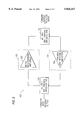
- FIG. 1 shows a prior art distribution plant. Line amplifiers 5 along distribution cable 3 amplify the bi-directional signals as they propagate. Now consider cable section 6 where the shielding of the cable has become damaged or worn.
- a radio source 7 such as a ham radio operator or AM radio broadcaster in the 5-30 MHz range, is shown.
- Radio waves 8 emanating from source 7 enter the distribution cable at weak point 6 and interfere with the reverse transmission.
- the 5-30 MHz band is particularly noisy because of the various radio sources (e.g., AM radio broadcasts and ham radio) that are present in that band.
- Common mode distortion is the result of non-linearities in the cable plant caused by connector corrosion creating point contact diodes.
- the effect of these diodes in the return plant is that difference products of driving signals consistently appear as noise power peaks at multiples of 6 MHz, i.e., 6, 12, 18, 24 and 30 MHz in the band of interest.
- Impulse noise is defined as noise consisting of impulses of high power level and short duration. Corona and gap impulse noise are created by power line discharge. Temperature and humidity are especially influential in determining the degree of corona noise, while gap noise is a direct result of a power system fault, for example, a bad or cracked insulator.
- the resultant impulse noise spectrum can extend into the tens of megahertz with a sin x/x distribution.
- Amplifier nonlinearities or oscillations relate to pulse regenerative oscillations caused by marginally stable or improperly terminated amplifiers.
- the result is a comb of frequency pecks within the return plant band whose spacing is related to the distance between the mistermination and the amplifier.
- Citta et al. conclude that a 45 kilobit data signal may be alternatively transmitted by a coherent phase shift keying (CPSK) technique over carriers at 5.5 MHz and 11.0 MHz or in the vicinity of the T7 and T8 cable television channels respectively.
- CPSK coherent phase shift keying
- a switch at the subscriber terminal alternately selects the 5.5 MHz carrier or the harmonically related 11 MHz carrier for transmission.
- This form of alternating carrier transmission of messages is continued until the data is successfully received.
- alternating transmission on the two carriers occurs until an acknowledgement signal indicating successful receipt of a message is received at a terminal. While the choice of these carrier frequencies is claimed to avoid the noise distribution peaks caused by interference noise, there is considerable concern that such a modulated phase shift keyed data stream will run into noise peaks in cable television distribution networks outside of the investigations of Citta et al.
- IPPV Impulse Pay Per View
- the subscriber terminal assumes that if the subscriber is pre-enabled for IPPV capability, then an event purchase is allowed.
- the subscriber terminal allows the event to be viewed (typically by de-scrambling a video signal on a particular channel) and records the purchase of the event.
- the record is typically stored in a secure, nonvolatile memory, as it represents revenue to the program vendor.
- the vendor's billing system must obtain the purchase record data stored in all of the subscriber terminals in a timely manner.
- the system control computer hereinafter called the system manager
- the system manager periodically requests that the subscriber terminals transmit the IPPV purchase data stored in memory.
- system manager receives the data from a subscriber terminal, it typically then acknowledges the receipt to the terminal and the data is cleared from memory to make room for additional purchase data. The system manager then forwards this data to the billing system, and the IPPV purchase cycle is completed.
- IPPV return data considerations are important to the determination of an RF data return technique, such IPPV return data considerations are not the only considerations.
- Other requirements such as for using the return data path for active device status monitoring, subscriber polling, burglar alarm, meter reading, home shopping, energy management, telephony and the like are additional to the data requirements of IPPV service.
- the present invention relates to bi-directionally transmitting data along a transmission path in a cable television system.
- the present invention is also particularly directed to addressing the problem of ingress noise from external sources, such as AM band broadcasts, ham radio broadcasts, etc., interfering with the RF data return transmissions.
- Applicants employ a high frequency reverse band and a lower frequency forward band.
- forward data is transmitted on the band of 46-735 MHz.
- the region from 735 MHz to 900 MHz provides an isolation region between the forward and reverse paths.
- a plurality of line amplifiers are placed on the data transmission path.
- Each line amplifier includes two diplex filters and two amplifiers.
- the first diplex filter includes a terminal that allows forward data signal input and provides reverse data signal output.
- the filter separates the high passband (900-1000 MHz) and low passband (46-735 MHz).
- the filter receives the reverse data signal from a 900-1000 MHz reverse amplifier and provides the forward data signal to a 46-735 MHz forward amplifier.
- the second diplex filter is identical to the first except it provides a terminal for receiving a reverse data signal and providing a forward data signal output.
- the second diplex filter also separates the high and low pass bands.
- the filter provides the reverse data signal to the 900-1000 MHz reverse amplifier and receives the forward data signal from the 46-735 MHz forward amplifier and provides the forward data signal at its terminal.
- the line amplifier serves to isolate, then amplify, the forward and reverse path transmissions.
- the diplex filters themselves are formed from both lumped and distributed components such as surface mounted capacitors and inductors, air wound inductors and microstrip inductors.
- the various components can be uniquely selected for operation over the 46-1000 MHz frequency range.
- a high degree of predictability is achieved and factory tuning is alleviated.
- filters can be provided that allow performance comparable to filters used for a low-band (5-30 MHz) reverse channel including high isolation.
- the design of the filters takes into consideration and combats problems associated with the 900-1000 MHz band, which are not encountered in the 5-30 MHz band.
- the filter combats the challenges of implementing small inductor values, maintaining high Q for transition band sharpness and designing to avoid parasitic self-resonances.
- the selected frequency band for reverse transmission provides an isolation band between the reverse path and forward path while providing a highly generous bandwidth for forward (downstream) services.
- FIG. 1 shows a prior art distribution plant
- FIG. 2 shows a simplified block diagram of a cable television system
- FIG. 3 shows a distribution network in accordance with the present invention
- FIG. 4 shows a simplified block diagram of a line amplifier in accordance with the present invention
- FIG. 5 shows a block diagram of a preferred embodiment of a line amplifier in accordance with the present invention
- FIG. 6 shows the details of a diplex filter in accordance with the present invention
- FIG. 7 shows a preferred embodiment of the present invention for use with an optical fiber distribution system.
- FIG. 2 is a simplified block diagram for a cable television system in accordance with the invention.
- the cable headend 30 communicates with subscriber terminal 10 through distribution plant 20.
- the distribution plant will often include optical fibers, fiber transmitters and receivers, coaxial cable, amplifiers and the like.
- Headend 30 transmits television signals and/or data signals to receiver (10b) of the subscriber terminal 10. While described in the cable television environment, it should be understood that the invention has applicablility to data transmission systems that do not include television signals.
- the headend could provide access to computer networks.
- Subscriber terminal 10 may also include a transmitter (10a) to transmit data signals to headend 30.
- data or “data signals” throughout this application, applicants refer to digital or analog data signals, including video, voice or other audio, or any other data representing information.
- the data transmitted by the subscriber is transmitted using quadrature phase shift keying modulation, but other types of modulation can be used and fall within the scope of the invention.
- the data signals transmitted from headend 30 to subscriber terminal 10 may include television programs as well as authorization information to authorize the subscriber to view certain programs, program information such as an electronic programming guide, or other information.
- the data signals transmitted from subscriber terminal 10 to headend 30 may include billing data for pay-per-view or impulse-pay-per-view programs, subscriber polling or voting information, alarm system information, telephony, etc.
- FIG. 3 shows a distribution network 20 in accordance with the present invention.
- a distribution cable 27 connects a headend to a plurality of subscribers.
- Line amplifiers 25 are placed at predetermined intervals along distribution cable 27.
- the line amplifiers serve to amplify the bi-directional signals to compensate for losses inherent in the transmission along distribution cable 27, whose loss at radio frequency increases in proportion to its length. Further, the amount of loss is dependent on transmitted frequency. The higher the frequency, the greater the loss over a given distance. As an example, consider an amplifier in this environment that raises the signal level by 30 db. Assume further that when propagating along distribution cable 27, the signal suffers a 30 db loss every mile. Then, to maintain signal strength, line amplifiers 25 would need to be placed at one mile intervals in order to maintain the signal above the level of undesirable noise.
- FIG. 4 is a simplified block diagram of a line amplifier 300 in accordance with the invention.
- the characteristic impedence of both the distribution cable and the line amplifier is 75 ohms.
- two diplex filters 350,360 are shown.
- Each diplex filter 350,360 is shown as comprising a low pass filter 310,320 and a high pass filter 330,340.
- Connected between low pass filters 310,320 is a forward amplifier 370 for the 46-735 MHz forward signal.
- Coupled between high pass filters 330,340 is a reverse amplifier 380 for the 900-1000 MHz reverse signal.
- the forward amplifier 370 may be a standard signal amplifier for the 46-735 MHz band.
- An example of such an amplifier is the Scientific Atlanta System Amplifier II, which is available in an 735 MHz model suitable for use with the instant invention.
- the reverse amplifier 380 may be of ultra-high frequency or microwave frequency design for operation in the 900-1000 MHz range.
- An example of such an amplifier is the Scientific Atlanta System Amplifier II, Reverse Module. The reverse module is available for the 900-1000 MHz range.
- the forward input signal is received at diplex filter 350. It passes through low pass filter 310, is amplified by forward amplifier 370, then passes through low pass filter 320 and proceeds along the distribution line to the subscribers. High pass filters 330,340 serve to prevent forward signals from reaching the reverse path.
- the reverse input signal is received at diplex filter 360.
- the reverse signal passes through high pass filter 340, is amplified by reverse amplifier 380 and finally passes through high pass filter 330 to continue along the distribution line to the headend.
- Low pass filters 310,320 serve to prevent reverse signals from reaching the forward path.
- diplex filters 350,360 are shown in FIG. 4 as each composed of two separate filters.
- the low pass filter and high pass filter (forming each of diplex filters 350,360) are incorporated into a single diplex filter circuit as illustrated in FIG. 5.
- the diplex filters 110,140 are tri-port circuits, whose operation will now be described in further detail below.
- FIG. 5 is a block diagram of a preferred embodiment of a line amplifier 100 in accordance with the invention.
- a first diplex filter 110 provides a terminal that receives forward input from the headend and provides an amplified return data signal from the subscriber.
- the diplex filter splits high band and low band signals so that only the forward data signal passes to 46-735 MHz forward amplifier 120 for amplification.
- a second diplex filter 140 receives a reverse data signal from a subscriber and provides an amplified forward data signal from the headend.
- the second diplex filter also splits the high band and low band signals so that only the reverse data signal passes to the 900-1000 MHz reverse amplifier 130.
- FIG. 6 shows the structure of a diplex filter 200 corresponding to filter 110 in FIG. 5.
- diplex filter 140 is identical to filter 110; only the inputs and outputs differ.
- Diplex filter 200 includes a high pass portion 201 and a low pass portion 202.
- the low pass portion 202 passes signals in the 46-735 MHz range.
- the high pass portion 201 passes signals in the 900-1000 MHz range.
- a forward signal enters the filter at the left terminal.
- Low band components (46-735 MHz in the preferred embodiment) are passed to the forward amplifier by low pass portion 202.
- high band components (900-1000 MHz in the preferred embodiment) are received from the reverse amplifier and passed to the reverse output by high pass portion 201.
- the lumped components include capacitors 205, 210, 215, 220, 226, 236 and 238.
- high precision capacitors 205, 210, 215, 220 and 226 are 1.8 pF, 2.2 pF, 3 pF, 2.4 pF and 11 pF, respectively.
- Capacitors 236 and 238 are each variable capacitors in the range of 0.5-4.5 pF, which are trimmed to achieve optimal performance.
- lumped component capacitors suitable for use in the filter are high precision capacitors sold by AVX Kyocera of Myrtle Beach, South Carolina under the tradename Accu F thin film series capacitors.
- the distributed components include elements 225, 230, 235 and 240.
- Distributed components are components that have highly predictive resistive, capacitive and inductive properties distributed over their length.
- the distributed components are sections of copper trace printed on a dielectric printed circuit board.
- the characteristics of the filter are determined by three variables associated with the distributed components in the preferred embodiment: 1) the width of the copper trace, 2) the thickness of the dielectric printed circuit board, and 3) length of the trace.
- strips of copper tape could be used as distributed components.
- dielectric board thickness equals 0.059 inches
- trace widths in each of elements 225, 230, 235 and 240 equal to 0.015 inches
- trace lengths in elements 225, 230, 235 and 240 of 0.433 inches, 0.611 inches, 1.121 inches and 0.754 inches, respectively.
- Low pass section 202 will now be described. With reference to FIG. 6, the low pass section is formed from solely lumped components. For example only, applicants have found that good performance is achieved with the following component values.
- Air wound inductors 260 and 265 are formed by two turns of 22 gauge copper wire having a core diameter of 0.14 inches. Inductors 270 and 275 are also formed from 22 gauge copper wire but only one-half turn of wire (i.e., "U" shape) is used. It is preferable to place inductors 260 and 265 such that the coil axes are perpendicular to each other to reduce interaction between the two components.
- diplex filter In a preferred embodiment all the components of the diplex filter are on a single printed circuit board. In a more preferred embodiment, both diplex filters and the two amplifiers are placed on a single printed circuit board to form an integrated line amplifier. The integrated unit can then be easily and effectively heavily shielded to prevent signal leakage.
- Each amplifier may further include an additional high pass or low pass filter. These optional filters are shown in FIG. 5 as boxes 121,131 surrounding the amplifiers 120,130 to indicate that additional filters may be used as part of the amplifier circuitry. These additional filters, which may include microstrip inductors, are used to provide extra forward signal rejection in the reverse band or reverse signal rejection in the forward band.
- the line amplifier may then preferably be placed in a weatherproof housing so that it may be suspended on an above-ground cable line or support pole or buried for an underground cable distribution system.
- the line amplifier may be used in an optical fiber transmission system by providing interface circuitry at each end of the line amplifier.
- the interface circuitry would include an optical receiver at each end of the line amplifier for receiving optical signals from the optical fiber and converting them into RF signals for use by the line amplifier.
- an optical receiver at each end of the line amplifier for receiving optical signals from the optical fiber and converting them into RF signals for use by the line amplifier.
- the interface circuitry would also include laser circuitry to accept RF signals from the line amplifier and convert the signals to optical pulses for continued transmission along the optical fiber. Such circuitry is well known in the art.
- FIG. 7 shows a preferred embodiment of the instant invention for use with an optical fiber distribution system.
- Elements 110, 120, 130 and 140 are the same as in FIG. 5 and no further explanation will be provided.
- optical interface units 600,610 are provided.
- Each interface unit 600,610 includes an optical receiver for receiving optical pulses from an optical fiber 620,630 and converting them to RP signals for use by the diplex filters 110,140 and amplifiers 120,130.
- Each interface unit 600,610 further includes laser circuitry for receiving an RF signal from diplex filters 110,140, respectively, and converting the signals to optical pulses for continued transmission along optical fibers 620,630.
- a forward signal is transmitted as optical pulses along optical fiber 620.
- Optical interface unit 600 receives the optical pulses and converts them to an RF signal of 46-735 MHz in the preferred embodiment.
- the forward signal passes to forward amplifier 120 (through diplex filter 110) for amplification and then to optical interface circuit 610 (though diplex filter 140).
- optical interface circuit 610 the RF signal is converted to optical pulses by laser circuitry within optical interface circuit 610.
- the optical pulses are then transmitted along optical fiber 630 toward the subscriber terminal.
- Reverse signals are received from optical fiber 630 as optical pulses.
- Optical interface 610 converts the optical pulses to an RF signal in the 900-1000 MHz range.
- the RF signal is then passed to reverse amplifier 130 (through diplex filter 140) for amplification.
- the RF signal is passed to optical interface unit 600 (through diplex filter 110), which converts the RF signal to optical pulses through the use of a laser circuit.
- the optical pulses are then transmitted toward the headend on optical fiber 620.
- a third frequency band (e.g., 5-30 MHz) lower than either of the ones described above may also be used to transmit data.
- data may include reverse transmission television signals.
- transmitters (10a) and (10c) may be located, for example, in a locations (10) and (11) remote from the headend (30) and connected to the distribution plant (20). These transmitters could then transmit upstream television signals. Accordingly upstream television signals could be transmitted on one upstream frequency band (e.g., 5-30 MHz) and other upstream data transmissions could be transmitted on another band (e.g., 900-1000 MHz).
- upstream frequency band e.g., 5-30 MHz
- other upstream data transmissions could be transmitted on another band (e.g., 900-1000 MHz).
- other configuration will be appreciated by those skilled in the art and fall within the scope of the invention, as limited only by the claims.
- the reverse band could be anywhere above the 550 MHz level.
- an isolation band should be provided to prevent interference between the two signals. Assuming a practical isolation band of 50 MHz, then the reverse transmission could occur anywhere above 600 MHz.
Abstract
Description
Claims (13)
Priority Applications (1)
| Application Number | Priority Date | Filing Date | Title |
|---|---|---|---|
| US08/838,333 US5826167A (en) | 1994-09-12 | 1997-04-08 | Bi-directional cable television system including a UHF filter |
Applications Claiming Priority (2)
| Application Number | Priority Date | Filing Date | Title |
|---|---|---|---|
| US30417194A | 1994-09-12 | 1994-09-12 | |
| US08/838,333 US5826167A (en) | 1994-09-12 | 1997-04-08 | Bi-directional cable television system including a UHF filter |
Related Parent Applications (1)
| Application Number | Title | Priority Date | Filing Date |
|---|---|---|---|
| US30417194A Continuation | 1994-09-12 | 1994-09-12 |
Publications (1)
| Publication Number | Publication Date |
|---|---|
| US5826167A true US5826167A (en) | 1998-10-20 |
Family
ID=23175388
Family Applications (1)
| Application Number | Title | Priority Date | Filing Date |
|---|---|---|---|
| US08/838,333 Expired - Lifetime US5826167A (en) | 1994-09-12 | 1997-04-08 | Bi-directional cable television system including a UHF filter |
Country Status (4)
| Country | Link |
|---|---|
| US (1) | US5826167A (en) |
| AU (1) | AU692600B2 (en) |
| CA (1) | CA2199815C (en) |
| WO (1) | WO1996008925A1 (en) |
Cited By (39)
| Publication number | Priority date | Publication date | Assignee | Title |
|---|---|---|---|---|
| WO1999038282A1 (en) * | 1998-01-21 | 1999-07-29 | Evolve Products, Inc. | Tap antenna unit |
| US6147700A (en) * | 1998-08-28 | 2000-11-14 | Samsung Electronics Co., Ltd. | Noise-having reverse signal isolator and reverse signal combining device in service system using CATV network |
| US20020093596A1 (en) * | 2001-01-18 | 2002-07-18 | Grasty William J. | Video amplifier circuits for multi-output distribution of video signals |
| US20020129379A1 (en) * | 1999-12-13 | 2002-09-12 | Levinson Frank H. | System and method for transmitting data on return path of a cable television system |
| US20020174435A1 (en) * | 2001-02-27 | 2002-11-21 | Hillel Weinstein | System, apparatus and method for expanding the operational bandwidth of a communication system |
| US6530088B1 (en) * | 1996-06-03 | 2003-03-04 | Scientific-Atlanta, Inc. | Apparatus for automatic sensing of line amplifier configuration for status monitoring |
| US20030110509A1 (en) * | 1999-12-13 | 2003-06-12 | Levinson Frank H. | Cable television return link system with high data-rate side-band communication channels |
| US20030113158A1 (en) * | 2001-12-14 | 2003-06-19 | Compaq Information Technologies Group, L.P. | Technique for providing a pivot structure that faciliates the rapid formation of pivot couplings between components |
| US6600900B1 (en) | 2000-05-09 | 2003-07-29 | John Mezzalingua Associates, Inc. | System and method providing bi-directional communication services between a service provider and a plurality of subscribers |
| US20030154498A1 (en) * | 2002-02-12 | 2003-08-14 | Sage Gerald F. | Efficient transmission of digital return path data in cable television return path |
| US20030154494A1 (en) * | 2002-02-08 | 2003-08-14 | Sage Gerald Francis | Bandpass component decimation and transmission of data in cable television digital return path |
| US20030154495A1 (en) * | 2002-02-12 | 2003-08-14 | Finisar Corporation | Data rate compression device for cable television return path using bandpass puncturing |
| US20030156602A1 (en) * | 2002-02-19 | 2003-08-21 | Sage Gerald F. | Asynchronous digital signal combiner and method of combining asynchronous digital signals in cable television return path |
| US6622304B1 (en) | 1996-09-09 | 2003-09-16 | Thomas W. Carhart | Interface system for computing apparatus and communications stations |
| US20040017514A1 (en) * | 2002-02-26 | 2004-01-29 | Adder Technology Limited | Video signal skew |
| US20040103441A1 (en) * | 2002-10-30 | 2004-05-27 | Williams Andrew R. | Return path transmitter with extended digital processing circuitry |
| US6751803B1 (en) * | 1999-05-24 | 2004-06-15 | Sharp Kabushiki Kaisha | Signal distribution circuit |
| US20040168200A1 (en) * | 2003-02-24 | 2004-08-26 | Microtune (Texas), L.P. | System and method for processing a common cable signal using a low-pass filter tap |
| WO2004105406A2 (en) * | 2003-05-21 | 2004-12-02 | Arris International, Inc. | Method and system for using broadcast channel frequencies to provide data services over an existing catv system |
| US20050155082A1 (en) * | 2001-02-27 | 2005-07-14 | Hillel Weinstein | Device, system and method for connecting a subscriber device to a wideband distribution network |
| US20050273837A1 (en) * | 2004-05-12 | 2005-12-08 | Oyadomari Randy I | Single master clock control of ethernet data transfer over both a cable TV return path and an ethernet forward path |
| US20050273836A1 (en) * | 2004-05-12 | 2005-12-08 | Oyadomari Randy I | Changing communication mode in a CATV pathway using mute commands |
| US20050283815A1 (en) * | 2004-06-01 | 2005-12-22 | Brooks Paul D | Apparatus and methods for network interface and spectrum management |
| US20060041922A1 (en) * | 2004-08-20 | 2006-02-23 | Shapson Jay F | Cable television reverse amplifier |
| US20060101501A1 (en) * | 2000-10-16 | 2006-05-11 | Zeev Orbach | System, device and method of expanding the operational bandwidth of a communication infrastructure |
| US20060195862A1 (en) * | 2005-02-28 | 2006-08-31 | Burak Olcen | Trap/filter verification system and method of use thereof |
| US20060271986A1 (en) * | 2005-05-23 | 2006-11-30 | Mark Vogel | Methods, gating devices, and computer program products for determining a noise source in a communication network |
| US20080040764A1 (en) * | 2001-07-20 | 2008-02-14 | Hillel Weinstein | System, apparatus and method for expanding the operational bandwidth of a communication system |
| US20080174386A1 (en) * | 2007-01-23 | 2008-07-24 | Syouji Ono | Diplexer and multiplexer using the same |
| US7519078B2 (en) | 2004-05-12 | 2009-04-14 | Finisar Corporation | Automated ethernet configuration of CATV network |
| US7519297B2 (en) | 2002-11-08 | 2009-04-14 | Finisar Corporation | Cable television system with separate radio frequency hub and ethernet hub |
| US20090119735A1 (en) * | 2000-10-16 | 2009-05-07 | Oleg Dounaevski | Wideband node in a catv network |
| US20090320085A1 (en) * | 2008-06-23 | 2009-12-24 | Jon-En Wang | House amplifier with return path gating |
| US7725036B2 (en) | 2002-02-12 | 2010-05-25 | Finisar Corporation | Efficient transmission of digital return path data in cable television return path |
| US20100223651A1 (en) * | 2008-06-23 | 2010-09-02 | Jon-En Wang | Amplifier with noise reduction |
| US20120110631A1 (en) * | 2010-01-22 | 2012-05-03 | Shlomo Selim Rakib | Hfc cable system with wideband communications pathway and coax domain nodes |
| US9326039B1 (en) | 2010-01-22 | 2016-04-26 | Gainspeed, Inc. | HFC cable system with shadow fiber and coax fiber terminals |
| US9521464B2 (en) | 2010-01-22 | 2016-12-13 | Gainspeed, Inc. | HFC cable system with alternative wideband communications pathways and coax domain amplifier-repeaters |
| US9826195B1 (en) | 2010-01-22 | 2017-11-21 | Alcatel-Lucent Usa Inc. | Methods of adaptive cancelling and secondary communications channels for extended capability HFC cable systems |
Families Citing this family (10)
| Publication number | Priority date | Publication date | Assignee | Title |
|---|---|---|---|---|
| US6307868B1 (en) | 1995-08-25 | 2001-10-23 | Terayon Communication Systems, Inc. | Apparatus and method for SCDMA digital data transmission using orthogonal codes and a head end modem with no tracking loops |
| GB2312137A (en) * | 1996-04-09 | 1997-10-15 | Northern Telecom Ltd | CATV for video/telecomms |
| EP0843480B1 (en) * | 1996-11-13 | 2003-04-16 | Alcatel | Method used in a telecommunication network, termination unit realising the latter and a telecommunication network including such a termination unit |
| NL1010769C2 (en) * | 1998-12-09 | 2000-06-13 | Ericsson Telefon Ab L M | Telecommunication system and connection device for use therein. |
| IL131192A (en) | 1999-08-01 | 2009-08-03 | Xtend Networks Ltd | Television multiplexing and transmission system |
| US7209497B2 (en) | 2001-11-26 | 2007-04-24 | Xtend Networks Ltd. | System and method for spectral node splitting in a hybrid fiber optic-coaxial cable network |
| SE0104420D0 (en) * | 2001-12-27 | 2001-12-27 | Dican Internat Ab | Method and device for bidirectional data transfer |
| AU2002258127A1 (en) | 2002-05-02 | 2003-11-17 | Xtend Networks Ltd. | A wideband catv signal splitter device |
| US20070061854A1 (en) * | 2002-11-21 | 2007-03-15 | Yechzkel Albag | Apparatus, system and method for the transmission of a dynamic bandwidth signal across a catv network |
| US8326037B1 (en) | 2005-11-23 | 2012-12-04 | Matrox Electronic Systems, Ltd. | Methods and apparatus for locating an object in an image |
Citations (99)
| Publication number | Priority date | Publication date | Assignee | Title |
|---|---|---|---|---|
| US3289271A (en) * | 1964-10-13 | 1966-12-06 | Willeys Carbide Tool Co | Indexable cutting inserts |
| GB1204190A (en) | 1966-12-26 | 1970-09-03 | Mainichi Broadcasting System | Multiplex communication system |
| US3806813A (en) * | 1972-06-26 | 1974-04-23 | Gte Sylvania Inc | Filter system for amplifier station for amplifying signals in separate frequency bands |
| US3891792A (en) * | 1974-06-25 | 1975-06-24 | Asahi Broadcasting | Television character crawl display method and apparatus |
| US4003005A (en) * | 1975-11-24 | 1977-01-11 | Electro Networks, Division Of Chloride, Inc. N. American Operations | Bidirectional constant impedance low pass/high pass filter circuit |
| US4247347A (en) * | 1979-03-19 | 1981-01-27 | Lischer James F | Process for molding cloth including a fabric layer by heating to at least the greater of the set or softening temperature the stitches thereof having never been set, and molding a cloth covered foam filled product |
| US4361848A (en) * | 1976-09-06 | 1982-11-30 | L'etat Francais | System for digitally transmitting and displaying data on television receiver screen |
| US4484217A (en) * | 1982-05-11 | 1984-11-20 | Telease, Inc. | Method and system for remote reporting, particularly for pay television billing |
| US4488179A (en) * | 1980-09-27 | 1984-12-11 | Robert Bosch Gmbh | Television viewing center system |
| DE3423846A1 (en) * | 1984-06-28 | 1986-01-09 | Telefunken Fernseh Und Rundfunk Gmbh, 3000 Hannover | Television receiver with a teletext decoder |
| EP0187961A2 (en) * | 1985-01-14 | 1986-07-23 | Oak Industries Inc. | Satellite scrambling communication network using geographically separated uplinks |
| US4605964A (en) * | 1981-12-19 | 1986-08-12 | Chard Frederick W | Method and apparatus for editing the output of a television set |
| US4639225A (en) * | 1982-06-24 | 1987-01-27 | Sharp Kabushiki Kaisha | Portable audio-visual electronic apparatus |
| US4688218A (en) * | 1981-07-15 | 1987-08-18 | Etablissement Public De Diffusion Dit "Telediffusion De France" | Multiplex channels for continuous flow for numerical signal |
| US4688246A (en) * | 1985-12-20 | 1987-08-18 | Zenith Electronics Corporation | CATV scrambling system with compressed digital audio in synchronizing signal intervals |
| EP0243312A2 (en) * | 1986-04-18 | 1987-10-28 | Nagra Plus S.A. | Decoder for a pay television system |
| US4706121A (en) * | 1985-07-12 | 1987-11-10 | Patrick Young | TV schedule system and process |
| US4712105A (en) * | 1985-03-12 | 1987-12-08 | U.S. Philips Corporation | Remote control hand apparatus for operating different modules |
| US4724491A (en) * | 1984-08-28 | 1988-02-09 | Adams-Russell Co., Inc. | Inserting television advertising spots automatically |
| GB2168227B (en) | 1984-11-22 | 1988-05-11 | Communications Patents Ltd | Interactive television distribution system |
| US4792972A (en) * | 1986-08-19 | 1988-12-20 | Scientific-Atlanta, Inc. | Remote programming of CATV channel authorization unit |
| US4826901A (en) * | 1985-09-07 | 1989-05-02 | Rohm Gmbh | Curable casting resins |
| US4829569A (en) * | 1984-09-21 | 1989-05-09 | Scientific-Atlanta, Inc. | Communication of individual messages to subscribers in a subscription television system |
| US4829558A (en) * | 1988-01-19 | 1989-05-09 | Peac Media Research, Inc. | System and device for data transmission, and related method |
| US4860379A (en) * | 1979-05-18 | 1989-08-22 | General Instrument Corporation | Data communications system |
| US4876736A (en) * | 1987-09-23 | 1989-10-24 | A. C. Nielsen Company | Method and apparatus for determining channel reception of a receiver |
| EP0355697A2 (en) * | 1988-08-19 | 1990-02-28 | Hitachi, Ltd. | Multimedia bidirectional broadcast system |
| US4928168A (en) * | 1988-08-08 | 1990-05-22 | Pioneer Electronic Corporation | Billing data display system and terminal used therein for a closed circuit television system |
| US4947429A (en) * | 1987-11-30 | 1990-08-07 | Zenith Electronics Corporation | Pay per view television signaling method |
| US4949187A (en) * | 1988-12-16 | 1990-08-14 | Cohen Jason M | Video communications system having a remotely controlled central source of video and audio data |
| US4959810A (en) * | 1987-10-14 | 1990-09-25 | Universal Electronics, Inc. | Universal remote control device |
| US4961109A (en) * | 1986-02-10 | 1990-10-02 | Pioneer Electronic Corporation | Chargeable program receiving limit setting system in two-way cable television system |
| US4966597A (en) * | 1988-11-04 | 1990-10-30 | Cosman Eric R | Thermometric cardiac tissue ablation electrode with ultra-sensitive temperature detection |
| US4975951A (en) * | 1988-10-07 | 1990-12-04 | General Instrument Corporation | IPPV programming distribution control system |
| US4977455A (en) * | 1988-07-15 | 1990-12-11 | Insight Telecast, Inc. | System and process for VCR scheduling |
| EP0402809A2 (en) * | 1989-06-13 | 1990-12-19 | Tv Answer International, Inc. | Satellite television communication system for audience polling and processing answers |
| US4995078A (en) * | 1988-06-09 | 1991-02-19 | Monslow H Vincent | Television broadcast system for selective transmission of viewer-chosen programs at viewer-requested times |
| US5001554A (en) * | 1988-12-23 | 1991-03-19 | Scientific-Atlanta, Inc. | Terminal authorization method |
| EP0420123A2 (en) * | 1989-09-27 | 1991-04-03 | Sanyo Electric Co., Ltd. | Program reserving apparatus for a video tape recorder capable of receiving teletext broadcasting |
| DE3935294A1 (en) * | 1989-10-24 | 1991-04-25 | Grundig Emv | VIDEORECORDER WITH A DEVICE FOR STORING THE CONTENTS OF A TAPE MAGAZINE CONTAINING A VARIETY OF MAGNETIC TAPE CASSETTES |
| EP0424648A2 (en) * | 1989-10-23 | 1991-05-02 | General Instrument Corporation Of Delaware | Method, system and apparatus for providing demographically targeted television commercials |
| EP0425834A2 (en) * | 1989-10-31 | 1991-05-08 | ALCATEL ITALIA Società per Azioni | System and multiplexer/ demultiplexer for the transmission/ reception of digital television information |
| US5015829A (en) * | 1989-04-28 | 1991-05-14 | Hewlett-Packard Company | Key pad and front panel assembly for an electronic instrument |
| US5020129A (en) * | 1990-04-16 | 1991-05-28 | General Instrument Corporation | Addressable control system for CATV program distribution |
| US5036394A (en) * | 1988-12-02 | 1991-07-30 | Matsushita Electric Industrial Co., Ltd. | Videotext receiver |
| US5036537A (en) * | 1984-11-19 | 1991-07-30 | General Instrument Corp. | Geographic black-out method for direct broadcast satellite system |
| US5046093A (en) * | 1989-09-05 | 1991-09-03 | General Instrument Corporation | CATV subscriber apparatus with intelligent remote control |
| US5047867A (en) * | 1989-06-08 | 1991-09-10 | North American Philips Corporation | Interface for a TV-VCR system |
| US5049990A (en) * | 1989-07-21 | 1991-09-17 | Sony Corporation | Highly efficient coding apparatus |
| US5057917A (en) * | 1990-06-20 | 1991-10-15 | The United States Of America As Represented By The Administrator Of The National Aeronautics And Space Administration | Real-time data compression of broadcast video signals |
| US5077607A (en) * | 1988-12-23 | 1991-12-31 | Scientific-Atlanta, Inc. | Cable television transaction terminal |
| US5078109A (en) * | 1989-01-31 | 1992-01-07 | Mitsubishi Jidosha Kogyo Kabushiki Kaisha | Engine output controlling method |
| US5091782A (en) * | 1990-04-09 | 1992-02-25 | General Instrument Corporation | Apparatus and method for adaptively compressing successive blocks of digital video |
| US5093718A (en) * | 1990-09-28 | 1992-03-03 | Inteletext Systems, Inc. | Interactive home information system |
| US5105268A (en) * | 1988-11-08 | 1992-04-14 | Fujitsu Limited | Community antenna broadcast system having an improved channel selecting system permitting purchase of a selected channel from a plurality of non-purchased channels |
| US5130792A (en) * | 1990-02-01 | 1992-07-14 | Usa Video Inc. | Store and forward video system |
| US5132789A (en) * | 1988-01-15 | 1992-07-21 | Tiltrac Corporation | Tilt rack video tape library and VCP to multiple subscriber system |
| US5133079A (en) * | 1990-07-30 | 1992-07-21 | Ballantyne Douglas J | Method and apparatus for distribution of movies |
| US5152011A (en) * | 1987-07-27 | 1992-09-29 | Schwob Pierre R | Broadcast receiver capable of automatic station identification and format-scanning based on an internal database updatable via data reception over the airwaves |
| US5151789A (en) * | 1989-10-30 | 1992-09-29 | Insight Telecast, Inc. | System and method for automatic, unattended recording of cable television programs |
| US5151782A (en) * | 1989-05-17 | 1992-09-29 | Reiss Media Enterprises | Control system for satellite delivered pay-per-view television system |
| EP0506435A2 (en) * | 1991-03-29 | 1992-09-30 | Scientific-Atlanta, Inc. | Independent external security module for a digitally upgradeable television signal decoder |
| EP0513763A2 (en) * | 1991-05-14 | 1992-11-19 | Fujitsu Limited | Television signal and ATM cell switching system |
| US5166886A (en) * | 1989-07-31 | 1992-11-24 | Molnar Charles E | System to demonstrate and sell computer programs |
| CA2044574A1 (en) * | 1991-06-13 | 1992-12-14 | Frederick James Anderson | Information distribution through a communication subscription system utilizing an interactive storage and retrieval device |
| US5172413A (en) * | 1990-12-20 | 1992-12-15 | Sasktel | Secure hierarchial video delivery system and method |
| US5182639A (en) * | 1991-10-30 | 1993-01-26 | Suganda Jutamulia | Real-time analytic pseudocolor encoder system |
| US5202817A (en) * | 1989-06-07 | 1993-04-13 | Norand Corporation | Hand-held data capture system with interchangeable modules |
| US5206722A (en) * | 1990-12-28 | 1993-04-27 | At&T Bell Laboratories | Remote channel switching for video on demand service |
| US5206954A (en) * | 1990-09-27 | 1993-04-27 | Masprodenkoh Kabushikikaisha | Satellite signal receiving apparatus |
| US5216515A (en) * | 1991-05-23 | 1993-06-01 | Adexpress Company | Addressable video feed system |
| US5223924A (en) * | 1992-05-27 | 1993-06-29 | North American Philips Corporation | System and method for automatically correlating user preferences with a T.V. program information database |
| US5237311A (en) * | 1991-08-01 | 1993-08-17 | Picker International, Inc. | Hingedly supported integrated trackball and selection device |
| US5253066A (en) * | 1989-06-01 | 1993-10-12 | Vogel Peter S | TV recording and viewing control system |
| US5253275A (en) * | 1991-01-07 | 1993-10-12 | H. Lee Browne | Audio and video transmission and receiving system |
| US5260778A (en) * | 1990-06-26 | 1993-11-09 | General Instrument Corporation | Apparatus for selective distribution of messages over a communications network |
| US5283639A (en) * | 1989-10-23 | 1994-02-01 | Esch Arthur G | Multiple media delivery network method and apparatus |
| US5293141A (en) * | 1991-03-25 | 1994-03-08 | Sanyo Electric Co., Ltd. | Dielectric filter having external connection terminals on dielectric substrate and antenna duplexer using the same |
| US5293540A (en) * | 1991-07-29 | 1994-03-08 | Nview Corporation | Method and apparatus for merging independently generated internal video with external video |
| US5323240A (en) * | 1992-02-07 | 1994-06-21 | Sony Corporation | Television receiver that automatically keeps track of favorite channels to facilitate tuning |
| US5327554A (en) * | 1990-11-29 | 1994-07-05 | Palazzi Iii Michael A | Interactive terminal for the access of remote database information |
| US5341166A (en) * | 1992-02-27 | 1994-08-23 | Video Control Technology, Inc. | System for controlling selected devices having unique sets of control codes |
| US5343239A (en) * | 1991-11-20 | 1994-08-30 | Zing Systems, L.P. | Transaction based interactive television system |
| US5343158A (en) * | 1991-08-28 | 1994-08-30 | U.S. Philips Corporation | Amplifier device for a cable television distribution network |
| US5345594A (en) * | 1991-01-31 | 1994-09-06 | Pioneer Electronic Corporation | Information transmission system retransmitting information signals according to retransmission schedule |
| US5353121A (en) * | 1989-10-30 | 1994-10-04 | Starsight Telecast, Inc. | Television schedule system |
| US5355162A (en) * | 1993-07-13 | 1994-10-11 | Pacific Ray Video Limited | Multi-standard cable television system |
| US5357276A (en) * | 1992-12-01 | 1994-10-18 | Scientific-Atlanta, Inc. | Method of providing video on demand with VCR like functions |
| US5367571A (en) * | 1992-12-02 | 1994-11-22 | Scientific-Atlanta, Inc. | Subscriber terminal with plug in expansion card |
| US5375068A (en) * | 1992-06-03 | 1994-12-20 | Digital Equipment Corporation | Video teleconferencing for networked workstations |
| US5390337A (en) * | 1992-05-01 | 1995-02-14 | Scientific-Atlanta, Inc. | Combination surge and diplex filter for CATV distribution systems |
| US5404393A (en) * | 1991-10-03 | 1995-04-04 | Viscorp | Method and apparatus for interactive television through use of menu windows |
| US5410326A (en) * | 1992-12-04 | 1995-04-25 | Goldstein; Steven W. | Programmable remote control device for interacting with a plurality of remotely controlled devices |
| US5410344A (en) * | 1993-09-22 | 1995-04-25 | Arrowsmith Technologies, Inc. | Apparatus and method of selecting video programs based on viewers' preferences |
| US5414426A (en) * | 1987-10-14 | 1995-05-09 | Universal Electronics Inc. | Favorite key macro command and chained macro command in a remote control |
| US5416508A (en) * | 1991-10-22 | 1995-05-16 | Pioneer Electronic Corporation | CATV system with transmission of program schedules, linked program broadcasts, and permissive ordering periods |
| US5421030A (en) * | 1991-09-17 | 1995-05-30 | Com21, Inc. | Communications system and method for bi-directional communications between an upstream control facility and downstream user terminals |
| US5425027A (en) * | 1993-01-04 | 1995-06-13 | Com21, Inc. | Wide area fiber and TV cable fast packet cell network |
| US5432542A (en) * | 1992-08-31 | 1995-07-11 | Television Computer, Inc. | Television receiver location identification |
Family Cites Families (4)
| Publication number | Priority date | Publication date | Assignee | Title |
|---|---|---|---|---|
| SE463540B (en) * | 1988-09-19 | 1990-12-03 | Ericsson Telefon Ab L M | SEAT TO DIGITALIZE ANY RADIO SIGNALS IN A RADIO COMMUNICATION SYSTEM AND DEVICE TO EXERCISE THE SET |
| SE462943B (en) * | 1989-01-26 | 1990-09-17 | Ericsson Telefon Ab L M | SETTING AND DEVICE FOR FREQUENCY CONTROL OF A COHERENT RADIO RECEIVER |
| JPH0812979B2 (en) * | 1989-11-21 | 1996-02-07 | 日本電気株式会社 | Automatic gain control device |
| US5335250A (en) * | 1992-10-22 | 1994-08-02 | Ericsson Ge Mobile Communications Inc. | Method and apparatus for bidirectional demodulation of digitally modulated signals |
-
1995
- 1995-08-30 WO PCT/US1995/010899 patent/WO1996008925A1/en active Application Filing
- 1995-08-30 AU AU34171/95A patent/AU692600B2/en not_active Ceased
- 1995-08-30 CA CA002199815A patent/CA2199815C/en not_active Expired - Fee Related
-
1997
- 1997-04-08 US US08/838,333 patent/US5826167A/en not_active Expired - Lifetime
Patent Citations (105)
| Publication number | Priority date | Publication date | Assignee | Title |
|---|---|---|---|---|
| US3289271A (en) * | 1964-10-13 | 1966-12-06 | Willeys Carbide Tool Co | Indexable cutting inserts |
| GB1204190A (en) | 1966-12-26 | 1970-09-03 | Mainichi Broadcasting System | Multiplex communication system |
| US3806813A (en) * | 1972-06-26 | 1974-04-23 | Gte Sylvania Inc | Filter system for amplifier station for amplifying signals in separate frequency bands |
| US3891792A (en) * | 1974-06-25 | 1975-06-24 | Asahi Broadcasting | Television character crawl display method and apparatus |
| US4003005A (en) * | 1975-11-24 | 1977-01-11 | Electro Networks, Division Of Chloride, Inc. N. American Operations | Bidirectional constant impedance low pass/high pass filter circuit |
| US4361848A (en) * | 1976-09-06 | 1982-11-30 | L'etat Francais | System for digitally transmitting and displaying data on television receiver screen |
| US4247347A (en) * | 1979-03-19 | 1981-01-27 | Lischer James F | Process for molding cloth including a fabric layer by heating to at least the greater of the set or softening temperature the stitches thereof having never been set, and molding a cloth covered foam filled product |
| US4860379A (en) * | 1979-05-18 | 1989-08-22 | General Instrument Corporation | Data communications system |
| US4488179A (en) * | 1980-09-27 | 1984-12-11 | Robert Bosch Gmbh | Television viewing center system |
| US4688218A (en) * | 1981-07-15 | 1987-08-18 | Etablissement Public De Diffusion Dit "Telediffusion De France" | Multiplex channels for continuous flow for numerical signal |
| US4605964A (en) * | 1981-12-19 | 1986-08-12 | Chard Frederick W | Method and apparatus for editing the output of a television set |
| US4484217A (en) * | 1982-05-11 | 1984-11-20 | Telease, Inc. | Method and system for remote reporting, particularly for pay television billing |
| US4639225A (en) * | 1982-06-24 | 1987-01-27 | Sharp Kabushiki Kaisha | Portable audio-visual electronic apparatus |
| DE3423846A1 (en) * | 1984-06-28 | 1986-01-09 | Telefunken Fernseh Und Rundfunk Gmbh, 3000 Hannover | Television receiver with a teletext decoder |
| US4724491A (en) * | 1984-08-28 | 1988-02-09 | Adams-Russell Co., Inc. | Inserting television advertising spots automatically |
| US4829569A (en) * | 1984-09-21 | 1989-05-09 | Scientific-Atlanta, Inc. | Communication of individual messages to subscribers in a subscription television system |
| US5036537A (en) * | 1984-11-19 | 1991-07-30 | General Instrument Corp. | Geographic black-out method for direct broadcast satellite system |
| GB2168227B (en) | 1984-11-22 | 1988-05-11 | Communications Patents Ltd | Interactive television distribution system |
| EP0187961A2 (en) * | 1985-01-14 | 1986-07-23 | Oak Industries Inc. | Satellite scrambling communication network using geographically separated uplinks |
| US4712105A (en) * | 1985-03-12 | 1987-12-08 | U.S. Philips Corporation | Remote control hand apparatus for operating different modules |
| US4706121A (en) * | 1985-07-12 | 1987-11-10 | Patrick Young | TV schedule system and process |
| US4706121B1 (en) * | 1985-07-12 | 1993-12-14 | Insight Telecast, Inc. | Tv schedule system and process |
| US4826901A (en) * | 1985-09-07 | 1989-05-02 | Rohm Gmbh | Curable casting resins |
| US4688246A (en) * | 1985-12-20 | 1987-08-18 | Zenith Electronics Corporation | CATV scrambling system with compressed digital audio in synchronizing signal intervals |
| US4961109A (en) * | 1986-02-10 | 1990-10-02 | Pioneer Electronic Corporation | Chargeable program receiving limit setting system in two-way cable television system |
| US5144663A (en) * | 1986-04-18 | 1992-09-01 | Kudelski S.A. Fabrique D'engregistreurs Nagra | Method of interactive communication between a subscriber and a decoder of a system of pay-television and decoder thereof |
| EP0243312A2 (en) * | 1986-04-18 | 1987-10-28 | Nagra Plus S.A. | Decoder for a pay television system |
| US4792972A (en) * | 1986-08-19 | 1988-12-20 | Scientific-Atlanta, Inc. | Remote programming of CATV channel authorization unit |
| US5152011A (en) * | 1987-07-27 | 1992-09-29 | Schwob Pierre R | Broadcast receiver capable of automatic station identification and format-scanning based on an internal database updatable via data reception over the airwaves |
| US4876736A (en) * | 1987-09-23 | 1989-10-24 | A. C. Nielsen Company | Method and apparatus for determining channel reception of a receiver |
| US4959810A (en) * | 1987-10-14 | 1990-09-25 | Universal Electronics, Inc. | Universal remote control device |
| US5414426A (en) * | 1987-10-14 | 1995-05-09 | Universal Electronics Inc. | Favorite key macro command and chained macro command in a remote control |
| US4947429A (en) * | 1987-11-30 | 1990-08-07 | Zenith Electronics Corporation | Pay per view television signaling method |
| US5132789A (en) * | 1988-01-15 | 1992-07-21 | Tiltrac Corporation | Tilt rack video tape library and VCP to multiple subscriber system |
| US4829558A (en) * | 1988-01-19 | 1989-05-09 | Peac Media Research, Inc. | System and device for data transmission, and related method |
| US4995078A (en) * | 1988-06-09 | 1991-02-19 | Monslow H Vincent | Television broadcast system for selective transmission of viewer-chosen programs at viewer-requested times |
| US4977455B1 (en) * | 1988-07-15 | 1993-04-13 | System and process for vcr scheduling | |
| US4977455A (en) * | 1988-07-15 | 1990-12-11 | Insight Telecast, Inc. | System and process for VCR scheduling |
| US4928168A (en) * | 1988-08-08 | 1990-05-22 | Pioneer Electronic Corporation | Billing data display system and terminal used therein for a closed circuit television system |
| EP0355697A2 (en) * | 1988-08-19 | 1990-02-28 | Hitachi, Ltd. | Multimedia bidirectional broadcast system |
| US5027400A (en) * | 1988-08-19 | 1991-06-25 | Hitachi Ltd. | Multimedia bidirectional broadcast system |
| US4975951A (en) * | 1988-10-07 | 1990-12-04 | General Instrument Corporation | IPPV programming distribution control system |
| US4966597A (en) * | 1988-11-04 | 1990-10-30 | Cosman Eric R | Thermometric cardiac tissue ablation electrode with ultra-sensitive temperature detection |
| US5105268A (en) * | 1988-11-08 | 1992-04-14 | Fujitsu Limited | Community antenna broadcast system having an improved channel selecting system permitting purchase of a selected channel from a plurality of non-purchased channels |
| US5036394A (en) * | 1988-12-02 | 1991-07-30 | Matsushita Electric Industrial Co., Ltd. | Videotext receiver |
| US4949187A (en) * | 1988-12-16 | 1990-08-14 | Cohen Jason M | Video communications system having a remotely controlled central source of video and audio data |
| US5001554A (en) * | 1988-12-23 | 1991-03-19 | Scientific-Atlanta, Inc. | Terminal authorization method |
| US5077607A (en) * | 1988-12-23 | 1991-12-31 | Scientific-Atlanta, Inc. | Cable television transaction terminal |
| US5078109A (en) * | 1989-01-31 | 1992-01-07 | Mitsubishi Jidosha Kogyo Kabushiki Kaisha | Engine output controlling method |
| US5015829A (en) * | 1989-04-28 | 1991-05-14 | Hewlett-Packard Company | Key pad and front panel assembly for an electronic instrument |
| US5151782A (en) * | 1989-05-17 | 1992-09-29 | Reiss Media Enterprises | Control system for satellite delivered pay-per-view television system |
| US5253066A (en) * | 1989-06-01 | 1993-10-12 | Vogel Peter S | TV recording and viewing control system |
| US5253066C1 (en) * | 1989-06-01 | 2001-05-22 | United Video Properties Inc | Tv recording and viewing control system |
| US5202817A (en) * | 1989-06-07 | 1993-04-13 | Norand Corporation | Hand-held data capture system with interchangeable modules |
| US5047867A (en) * | 1989-06-08 | 1991-09-10 | North American Philips Corporation | Interface for a TV-VCR system |
| EP0402809A2 (en) * | 1989-06-13 | 1990-12-19 | Tv Answer International, Inc. | Satellite television communication system for audience polling and processing answers |
| US5049990A (en) * | 1989-07-21 | 1991-09-17 | Sony Corporation | Highly efficient coding apparatus |
| US5166886A (en) * | 1989-07-31 | 1992-11-24 | Molnar Charles E | System to demonstrate and sell computer programs |
| US5046093A (en) * | 1989-09-05 | 1991-09-03 | General Instrument Corporation | CATV subscriber apparatus with intelligent remote control |
| EP0420123A2 (en) * | 1989-09-27 | 1991-04-03 | Sanyo Electric Co., Ltd. | Program reserving apparatus for a video tape recorder capable of receiving teletext broadcasting |
| EP0424648A2 (en) * | 1989-10-23 | 1991-05-02 | General Instrument Corporation Of Delaware | Method, system and apparatus for providing demographically targeted television commercials |
| US5155591A (en) * | 1989-10-23 | 1992-10-13 | General Instrument Corporation | Method and apparatus for providing demographically targeted television commercials |
| US5283639A (en) * | 1989-10-23 | 1994-02-01 | Esch Arthur G | Multiple media delivery network method and apparatus |
| DE3935294A1 (en) * | 1989-10-24 | 1991-04-25 | Grundig Emv | VIDEORECORDER WITH A DEVICE FOR STORING THE CONTENTS OF A TAPE MAGAZINE CONTAINING A VARIETY OF MAGNETIC TAPE CASSETTES |
| US5151789A (en) * | 1989-10-30 | 1992-09-29 | Insight Telecast, Inc. | System and method for automatic, unattended recording of cable television programs |
| US5353121A (en) * | 1989-10-30 | 1994-10-04 | Starsight Telecast, Inc. | Television schedule system |
| EP0425834A2 (en) * | 1989-10-31 | 1991-05-08 | ALCATEL ITALIA Società per Azioni | System and multiplexer/ demultiplexer for the transmission/ reception of digital television information |
| US5130792A (en) * | 1990-02-01 | 1992-07-14 | Usa Video Inc. | Store and forward video system |
| US5091782A (en) * | 1990-04-09 | 1992-02-25 | General Instrument Corporation | Apparatus and method for adaptively compressing successive blocks of digital video |
| US5020129A (en) * | 1990-04-16 | 1991-05-28 | General Instrument Corporation | Addressable control system for CATV program distribution |
| US5057917A (en) * | 1990-06-20 | 1991-10-15 | The United States Of America As Represented By The Administrator Of The National Aeronautics And Space Administration | Real-time data compression of broadcast video signals |
| US5260778A (en) * | 1990-06-26 | 1993-11-09 | General Instrument Corporation | Apparatus for selective distribution of messages over a communications network |
| US5133079A (en) * | 1990-07-30 | 1992-07-21 | Ballantyne Douglas J | Method and apparatus for distribution of movies |
| US5206954A (en) * | 1990-09-27 | 1993-04-27 | Masprodenkoh Kabushikikaisha | Satellite signal receiving apparatus |
| US5093718A (en) * | 1990-09-28 | 1992-03-03 | Inteletext Systems, Inc. | Interactive home information system |
| US5327554A (en) * | 1990-11-29 | 1994-07-05 | Palazzi Iii Michael A | Interactive terminal for the access of remote database information |
| US5172413A (en) * | 1990-12-20 | 1992-12-15 | Sasktel | Secure hierarchial video delivery system and method |
| US5206722A (en) * | 1990-12-28 | 1993-04-27 | At&T Bell Laboratories | Remote channel switching for video on demand service |
| US5253275A (en) * | 1991-01-07 | 1993-10-12 | H. Lee Browne | Audio and video transmission and receiving system |
| US5345594A (en) * | 1991-01-31 | 1994-09-06 | Pioneer Electronic Corporation | Information transmission system retransmitting information signals according to retransmission schedule |
| US5293141A (en) * | 1991-03-25 | 1994-03-08 | Sanyo Electric Co., Ltd. | Dielectric filter having external connection terminals on dielectric substrate and antenna duplexer using the same |
| EP0506435A2 (en) * | 1991-03-29 | 1992-09-30 | Scientific-Atlanta, Inc. | Independent external security module for a digitally upgradeable television signal decoder |
| EP0513763A2 (en) * | 1991-05-14 | 1992-11-19 | Fujitsu Limited | Television signal and ATM cell switching system |
| US5216515A (en) * | 1991-05-23 | 1993-06-01 | Adexpress Company | Addressable video feed system |
| CA2044574A1 (en) * | 1991-06-13 | 1992-12-14 | Frederick James Anderson | Information distribution through a communication subscription system utilizing an interactive storage and retrieval device |
| US5293540A (en) * | 1991-07-29 | 1994-03-08 | Nview Corporation | Method and apparatus for merging independently generated internal video with external video |
| US5237311A (en) * | 1991-08-01 | 1993-08-17 | Picker International, Inc. | Hingedly supported integrated trackball and selection device |
| US5343158A (en) * | 1991-08-28 | 1994-08-30 | U.S. Philips Corporation | Amplifier device for a cable television distribution network |
| US5421030A (en) * | 1991-09-17 | 1995-05-30 | Com21, Inc. | Communications system and method for bi-directional communications between an upstream control facility and downstream user terminals |
| US5404393A (en) * | 1991-10-03 | 1995-04-04 | Viscorp | Method and apparatus for interactive television through use of menu windows |
| US5416508A (en) * | 1991-10-22 | 1995-05-16 | Pioneer Electronic Corporation | CATV system with transmission of program schedules, linked program broadcasts, and permissive ordering periods |
| US5182639A (en) * | 1991-10-30 | 1993-01-26 | Suganda Jutamulia | Real-time analytic pseudocolor encoder system |
| US5343239A (en) * | 1991-11-20 | 1994-08-30 | Zing Systems, L.P. | Transaction based interactive television system |
| US5323240A (en) * | 1992-02-07 | 1994-06-21 | Sony Corporation | Television receiver that automatically keeps track of favorite channels to facilitate tuning |
| US5341166A (en) * | 1992-02-27 | 1994-08-23 | Video Control Technology, Inc. | System for controlling selected devices having unique sets of control codes |
| US5390337A (en) * | 1992-05-01 | 1995-02-14 | Scientific-Atlanta, Inc. | Combination surge and diplex filter for CATV distribution systems |
| US5223924A (en) * | 1992-05-27 | 1993-06-29 | North American Philips Corporation | System and method for automatically correlating user preferences with a T.V. program information database |
| US5375068A (en) * | 1992-06-03 | 1994-12-20 | Digital Equipment Corporation | Video teleconferencing for networked workstations |
| US5432542A (en) * | 1992-08-31 | 1995-07-11 | Television Computer, Inc. | Television receiver location identification |
| US5357276A (en) * | 1992-12-01 | 1994-10-18 | Scientific-Atlanta, Inc. | Method of providing video on demand with VCR like functions |
| US5367571A (en) * | 1992-12-02 | 1994-11-22 | Scientific-Atlanta, Inc. | Subscriber terminal with plug in expansion card |
| US5410326A (en) * | 1992-12-04 | 1995-04-25 | Goldstein; Steven W. | Programmable remote control device for interacting with a plurality of remotely controlled devices |
| US5425027A (en) * | 1993-01-04 | 1995-06-13 | Com21, Inc. | Wide area fiber and TV cable fast packet cell network |
| US5355162A (en) * | 1993-07-13 | 1994-10-11 | Pacific Ray Video Limited | Multi-standard cable television system |
| US5410344A (en) * | 1993-09-22 | 1995-04-25 | Arrowsmith Technologies, Inc. | Apparatus and method of selecting video programs based on viewers' preferences |
Non-Patent Citations (12)
| Title |
|---|
| "Two-Way Cable Plant Charateristics", Richard Citta and Dennis Mutzabaugh, Technical Papers, NCTA Jun. 3-6, 1984, pp. 270-277. |
| A Store and Forward . . . , Gelman et al., Jun. 21, 1991. * |
| A Store-and-Forward . . . , Gelman et al., Jun. 21, 1991. |
| Digital Compression in Todays . . . , Moloney, Jun. 6, 1993. * |
| Flexible Data Structures . . . , Bestler, Jun. 6, 1993. * |
| Interactive Videotex . . . , van den Boom, Nov. Dec. 1986. * |
| Interactive Videotex . . . , van den Boom, Nov.-Dec. 1986. |
| Market and Products Overview, Dinaro et al. 1991. * |
| Memories In My Pocket, Reimer, Feb. 1991. * |
| Subscriber Distribution Networks Using Compressed Digital Video, Olshansky et al., Nov., 1992. * |
| Subscription teletext for value added services, Sharpless, Aug. 1985. * |
| Two Way Cable Plant Charateristics , Richard Citta and Dennis Mutzabaugh, Technical Papers, NCTA Jun. 3 6, 1984, pp. 270 277. * |
Cited By (68)
| Publication number | Priority date | Publication date | Assignee | Title |
|---|---|---|---|---|
| US6530088B1 (en) * | 1996-06-03 | 2003-03-04 | Scientific-Atlanta, Inc. | Apparatus for automatic sensing of line amplifier configuration for status monitoring |
| US6622304B1 (en) | 1996-09-09 | 2003-09-16 | Thomas W. Carhart | Interface system for computing apparatus and communications stations |
| US6154204A (en) * | 1998-01-21 | 2000-11-28 | Evolve Products, Inc. | Tap antenna unit |
| AU746141B2 (en) * | 1998-01-21 | 2002-04-18 | Evolve Communications, Inc. | Tap antenna unit |
| WO1999038282A1 (en) * | 1998-01-21 | 1999-07-29 | Evolve Products, Inc. | Tap antenna unit |
| US6147700A (en) * | 1998-08-28 | 2000-11-14 | Samsung Electronics Co., Ltd. | Noise-having reverse signal isolator and reverse signal combining device in service system using CATV network |
| US6751803B1 (en) * | 1999-05-24 | 2004-06-15 | Sharp Kabushiki Kaisha | Signal distribution circuit |
| US20030110509A1 (en) * | 1999-12-13 | 2003-06-12 | Levinson Frank H. | Cable television return link system with high data-rate side-band communication channels |
| US20020129379A1 (en) * | 1999-12-13 | 2002-09-12 | Levinson Frank H. | System and method for transmitting data on return path of a cable television system |
| US7257328B2 (en) | 1999-12-13 | 2007-08-14 | Finisar Corporation | System and method for transmitting data on return path of a cable television system |
| US7222358B2 (en) | 1999-12-13 | 2007-05-22 | Finisar Corporation | Cable television return link system with high data-rate side-band communication channels |
| US7529487B2 (en) | 1999-12-13 | 2009-05-05 | Finisar Corporation | System and method for transmitting data on return path of a cable television system |
| US20080019706A1 (en) * | 1999-12-13 | 2008-01-24 | Finisar Corporation | System and method for transmitting data on return path of a cable television system |
| US7778554B2 (en) | 1999-12-13 | 2010-08-17 | Finisar Corporation | System and method for transmitting data on return path of a cable television system |
| US6600900B1 (en) | 2000-05-09 | 2003-07-29 | John Mezzalingua Associates, Inc. | System and method providing bi-directional communication services between a service provider and a plurality of subscribers |
| US7616890B2 (en) | 2000-10-16 | 2009-11-10 | Xtend Networks Ltd. | System, device and method of expanding the operational bandwidth of a communication infrastructure |
| US20090119735A1 (en) * | 2000-10-16 | 2009-05-07 | Oleg Dounaevski | Wideband node in a catv network |
| US20060101501A1 (en) * | 2000-10-16 | 2006-05-11 | Zeev Orbach | System, device and method of expanding the operational bandwidth of a communication infrastructure |
| US7904932B2 (en) | 2000-10-16 | 2011-03-08 | Xtend Networks Ltd. | Wideband node in a CATV network |
| US20020093596A1 (en) * | 2001-01-18 | 2002-07-18 | Grasty William J. | Video amplifier circuits for multi-output distribution of video signals |
| US20020174435A1 (en) * | 2001-02-27 | 2002-11-21 | Hillel Weinstein | System, apparatus and method for expanding the operational bandwidth of a communication system |
| US20050155082A1 (en) * | 2001-02-27 | 2005-07-14 | Hillel Weinstein | Device, system and method for connecting a subscriber device to a wideband distribution network |
| US7748023B2 (en) | 2001-02-27 | 2010-06-29 | Xtend Networks Ltd. | Device, system and method for connecting a subscriber device to a wideband distribution network |
| US20080040764A1 (en) * | 2001-07-20 | 2008-02-14 | Hillel Weinstein | System, apparatus and method for expanding the operational bandwidth of a communication system |
| US20030113158A1 (en) * | 2001-12-14 | 2003-06-19 | Compaq Information Technologies Group, L.P. | Technique for providing a pivot structure that faciliates the rapid formation of pivot couplings between components |
| US7971225B2 (en) | 2002-02-08 | 2011-06-28 | Finisar Corporation | Bandpass component decimation and transmission of data in cable television digital return path |
| US20030154494A1 (en) * | 2002-02-08 | 2003-08-14 | Sage Gerald Francis | Bandpass component decimation and transmission of data in cable television digital return path |
| US8156535B2 (en) | 2002-02-12 | 2012-04-10 | Finsar Corporation | Data rate compression device for cable television return path using bandpass puncturing |
| US20030154495A1 (en) * | 2002-02-12 | 2003-08-14 | Finisar Corporation | Data rate compression device for cable television return path using bandpass puncturing |
| US20030154498A1 (en) * | 2002-02-12 | 2003-08-14 | Sage Gerald F. | Efficient transmission of digital return path data in cable television return path |
| US7725036B2 (en) | 2002-02-12 | 2010-05-25 | Finisar Corporation | Efficient transmission of digital return path data in cable television return path |
| US7751718B2 (en) | 2002-02-12 | 2010-07-06 | Finisar Corporation | Efficient transmission of digital return path data in cable television return path |
| US20030156602A1 (en) * | 2002-02-19 | 2003-08-21 | Sage Gerald F. | Asynchronous digital signal combiner and method of combining asynchronous digital signals in cable television return path |
| US7359447B2 (en) | 2002-02-19 | 2008-04-15 | Finisar Corporation | Asynchronous digital signal combiner and method of combining asynchronous digital signals in cable television return path |
| US20040017514A1 (en) * | 2002-02-26 | 2004-01-29 | Adder Technology Limited | Video signal skew |
| US7277104B2 (en) * | 2002-02-26 | 2007-10-02 | Adder Technology Ltd. | Video signal skew |
| US20040103441A1 (en) * | 2002-10-30 | 2004-05-27 | Williams Andrew R. | Return path transmitter with extended digital processing circuitry |
| US7689128B2 (en) | 2002-10-30 | 2010-03-30 | Finisar Corporation | Return path transmitter with extended digital processing circuitry |
| US7519297B2 (en) | 2002-11-08 | 2009-04-14 | Finisar Corporation | Cable television system with separate radio frequency hub and ethernet hub |
| US20040168200A1 (en) * | 2003-02-24 | 2004-08-26 | Microtune (Texas), L.P. | System and method for processing a common cable signal using a low-pass filter tap |
| US8898725B2 (en) | 2003-02-24 | 2014-11-25 | CSR Technology, Inc. | System and method for processing a common cable signal using a low-pass filter tap |
| US8302147B2 (en) * | 2003-02-24 | 2012-10-30 | Csr Technology Inc. | System and method for processing a common cable signal using a low-pass filter tap |
| WO2004105406A2 (en) * | 2003-05-21 | 2004-12-02 | Arris International, Inc. | Method and system for using broadcast channel frequencies to provide data services over an existing catv system |
| US20050010962A1 (en) * | 2003-05-21 | 2005-01-13 | Mark Bugajski | Method and system for using broadcast channel frequencies to provide data services over an existing CATV system |
| WO2004105406A3 (en) * | 2003-05-21 | 2008-01-17 | Arris Int Inc | Method and system for using broadcast channel frequencies to provide data services over an existing catv system |
| US7519078B2 (en) | 2004-05-12 | 2009-04-14 | Finisar Corporation | Automated ethernet configuration of CATV network |
| US8032916B2 (en) | 2004-05-12 | 2011-10-04 | Finisar Corporation | Single master clock control of Ethernet data transfer over both a cable TV return path and an Ethernet forward path |
| US20050273836A1 (en) * | 2004-05-12 | 2005-12-08 | Oyadomari Randy I | Changing communication mode in a CATV pathway using mute commands |
| US20050273837A1 (en) * | 2004-05-12 | 2005-12-08 | Oyadomari Randy I | Single master clock control of ethernet data transfer over both a cable TV return path and an ethernet forward path |
| US7765576B2 (en) | 2004-05-12 | 2010-07-27 | Finsiar Corporation | Changing communication mode in a CATV pathway using mute commands |
| US20050283815A1 (en) * | 2004-06-01 | 2005-12-22 | Brooks Paul D | Apparatus and methods for network interface and spectrum management |
| US8095098B2 (en) * | 2004-06-01 | 2012-01-10 | Time Warner Cable Inc. | Apparatus and methods for network interface and spectrum management |
| US7577983B2 (en) | 2004-08-20 | 2009-08-18 | Extreme Broadband Engineering, Llc | Cable television reverse amplifier |
| US20060041922A1 (en) * | 2004-08-20 | 2006-02-23 | Shapson Jay F | Cable television reverse amplifier |
| US20060195862A1 (en) * | 2005-02-28 | 2006-08-31 | Burak Olcen | Trap/filter verification system and method of use thereof |
| US20060271986A1 (en) * | 2005-05-23 | 2006-11-30 | Mark Vogel | Methods, gating devices, and computer program products for determining a noise source in a communication network |
| EP1953914A3 (en) * | 2007-01-23 | 2008-09-17 | Ngk Spark Plug Co., Ltd. | Diplexer and multiplexer using the same |
| US7924116B2 (en) | 2007-01-23 | 2011-04-12 | Ngk Spark Plug Co., Ltd. | Diplexer and multiplexer using the same |
| US20080174386A1 (en) * | 2007-01-23 | 2008-07-24 | Syouji Ono | Diplexer and multiplexer using the same |
| US8667550B2 (en) | 2008-06-23 | 2014-03-04 | Pct International, Inc. | House amplifier with return path gating |
| US20100223651A1 (en) * | 2008-06-23 | 2010-09-02 | Jon-En Wang | Amplifier with noise reduction |
| US8769597B2 (en) | 2008-06-23 | 2014-07-01 | Pct International, Inc. | Amplifier with noise reduction |
| US20090320085A1 (en) * | 2008-06-23 | 2009-12-24 | Jon-En Wang | House amplifier with return path gating |
| US20120110631A1 (en) * | 2010-01-22 | 2012-05-03 | Shlomo Selim Rakib | Hfc cable system with wideband communications pathway and coax domain nodes |
| US8510786B2 (en) * | 2010-01-22 | 2013-08-13 | Shlomo Selim Rakib | HFC cable system with wideband communications pathway and coax domain nodes |
| US9326039B1 (en) | 2010-01-22 | 2016-04-26 | Gainspeed, Inc. | HFC cable system with shadow fiber and coax fiber terminals |
| US9521464B2 (en) | 2010-01-22 | 2016-12-13 | Gainspeed, Inc. | HFC cable system with alternative wideband communications pathways and coax domain amplifier-repeaters |
| US9826195B1 (en) | 2010-01-22 | 2017-11-21 | Alcatel-Lucent Usa Inc. | Methods of adaptive cancelling and secondary communications channels for extended capability HFC cable systems |
Also Published As
| Publication number | Publication date |
|---|---|
| AU3417195A (en) | 1996-03-29 |
| CA2199815A1 (en) | 1996-03-21 |
| AU692600B2 (en) | 1998-06-11 |
| CA2199815C (en) | 2001-07-24 |
| WO1996008925A1 (en) | 1996-03-21 |
Similar Documents
| Publication | Publication Date | Title |
|---|---|---|
| US5826167A (en) | Bi-directional cable television system including a UHF filter | |
| US5235619A (en) | Cable television radio frequency subscriber data transmission apparatus and rf return method | |
| EP0532503B1 (en) | Cable television radio frequency subscriber data transmission apparatus and calibration method | |
| EP0576586A4 (en) | ||
| CA2078562A1 (en) | Cable television radio frequency data processor | |
| CA2234024C (en) | System to reduce gain variance and ingress in catv return transmissions | |
| US5045816A (en) | Binary phase shift key modulator with programmable level control | |
| AU698649B2 (en) | Cable television apparatus employing two-way communication | |
| US6990682B1 (en) | Two-way CATV system | |
| US6600900B1 (en) | System and method providing bi-directional communication services between a service provider and a plurality of subscribers | |
| AU641755B2 (en) | Cable television radio frequency return method | |
| US20090260049A1 (en) | Automatic drop/house return termination system | |
| JPH10174084A (en) | Two-way catv system | |
| WO2018213384A1 (en) | Combined equalizer and attenuator for reverse path optical nodes and methods for making and using same | |
| KR200143238Y1 (en) | Catv signal dsitributing circuit | |
| Evans et al. | An intercity broadband network for rural Manitoba | |
| JPS6127952B2 (en) | ||
| Mends-Cole | Operational issues in a two-way HFC environment | |
| KR20010100257A (en) | Wireless transfer system for multi-cahannel television | |
| WO2001073456A1 (en) | Return path amplifier device for hfc network |
Legal Events
| Date | Code | Title | Description |
|---|---|---|---|
| STCF | Information on status: patent grant |
Free format text: PATENTED CASE |
|
| FPAY | Fee payment |
Year of fee payment: 4 |
|
| FPAY | Fee payment |
Year of fee payment: 8 |
|
| FPAY | Fee payment |
Year of fee payment: 12 |
|
| AS | Assignment |
Owner name: SCIENTIFIC-ATLANTA, LLC, GEORGIA Free format text: CHANGE OF NAME;ASSIGNOR:SCIENTIFIC-ATLANTA, INC.;REEL/FRAME:034299/0440 Effective date: 20081205 Owner name: CISCO TECHNOLOGY, INC., CALIFORNIA Free format text: ASSIGNMENT OF ASSIGNORS INTEREST;ASSIGNOR:SCIENTIFIC-ATLANTA, LLC;REEL/FRAME:034300/0001 Effective date: 20141118 |