US5818581A - Elemental analysis method and apparatus - Google Patents
Elemental analysis method and apparatus Download PDFInfo
- Publication number
- US5818581A US5818581A US08/774,837 US77483796A US5818581A US 5818581 A US5818581 A US 5818581A US 77483796 A US77483796 A US 77483796A US 5818581 A US5818581 A US 5818581A
- Authority
- US
- United States
- Prior art keywords
- sample
- plasma
- torch
- flow
- atom
- Prior art date
- Legal status (The legal status is an assumption and is not a legal conclusion. Google has not performed a legal analysis and makes no representation as to the accuracy of the status listed.)
- Expired - Lifetime
Links
Images


Classifications
-
- G—PHYSICS
- G01—MEASURING; TESTING
- G01N—INVESTIGATING OR ANALYSING MATERIALS BY DETERMINING THEIR CHEMICAL OR PHYSICAL PROPERTIES
- G01N21/00—Investigating or analysing materials by the use of optical means, i.e. using sub-millimetre waves, infrared, visible or ultraviolet light
- G01N21/62—Systems in which the material investigated is excited whereby it emits light or causes a change in wavelength of the incident light
- G01N21/71—Systems in which the material investigated is excited whereby it emits light or causes a change in wavelength of the incident light thermally excited
- G01N21/73—Systems in which the material investigated is excited whereby it emits light or causes a change in wavelength of the incident light thermally excited using plasma burners or torches
-
- H—ELECTRICITY
- H01—ELECTRIC ELEMENTS
- H01J—ELECTRIC DISCHARGE TUBES OR DISCHARGE LAMPS
- H01J49/00—Particle spectrometers or separator tubes
- H01J49/02—Details
- H01J49/10—Ion sources; Ion guns
- H01J49/105—Ion sources; Ion guns using high-frequency excitation, e.g. microwave excitation, Inductively Coupled Plasma [ICP]
-
- H—ELECTRICITY
- H05—ELECTRIC TECHNIQUES NOT OTHERWISE PROVIDED FOR
- H05H—PLASMA TECHNIQUE; PRODUCTION OF ACCELERATED ELECTRICALLY-CHARGED PARTICLES OR OF NEUTRONS; PRODUCTION OR ACCELERATION OF NEUTRAL MOLECULAR OR ATOMIC BEAMS
- H05H1/00—Generating plasma; Handling plasma
- H05H1/24—Generating plasma
- H05H1/26—Plasma torches
- H05H1/30—Plasma torches using applied electromagnetic fields, e.g. high frequency or microwave energy
Abstract
In an elemental analysis method of analyzing a sample as an analysis target using atoms generated upon dissociation of the sample, a plasma is generated using a gas serving as a plasma source to be supplied in a torch having a conical cylinder thereof. A sample flow obtained by evaporating the sample using the gas as a carrier gas or a sample flow containing a component of the sample is supplied to the plasma. The sample flow or the plasma containing the sample flow is changed into a spiral flow, and the component of the sample is dissociated. The sample is analyzed in accordance with the state of an atom generated by dissociation of the component of the sample. An elemental analysis apparatus is also disclosed.
Description
The present invention relates to an elemental analysis method and apparatus.
General analysis methods of elements contained in samples are atomic-emission spectroscopy, atomic absorption spectroscopy, mass spectroscopy, and the like. Among them all, RF inductively coupled plasma (ICP)-mass spectroscopy using an RF inductively coupled plasma torch is very popular because of its features excellent in sensitivity and accuracy. The RF inductively coupled plasma-mass spectroscopy has a higher detection limit than that of RF inductively coupled plasma-atomic emission spectroscopy by three or more orders of magnitude and can analyze the concentration of an element on the order of ppt or less.
A method of increasing the sensitivity in elemental analysis is to provide a higher-sensitivity detection system and a higher-efficiency sample supply system. Detection systems have been improved by employing a higher-sensitivity detection method and a high-transmittance detector. In an analysis method using an RF inductively coupled plasma torch, a detection method is changed from a method using a mass spectrometer to RF inductively coupled plasma-mass spectroscopy using a high-sensitivity plasma system spectrometer. This makes it possible to obtain a higher sensitivity than that of the RF inductively coupled plasma-atomic emission spectroscopy by three or more orders of magnitude. In the RF inductively coupled plasma-mass spectroscopy, a double focusing mass spectrometer is employed in place of a quadrupole mass spectrometer to increase the sensitivity, and an apparatus having a detection limit of ppq which is 1/1000 of ppt is commercially available.
The efficiency of a sample supply system has been improved by the development of an ultrasonic nebulizer and a desolvating nebulizer. It is known that the sensitivity in use of such a nebulizer can increase that in use of an ordinary nebulizer by about one to two orders of magnitude.
Industry of high purity materials such as semiconductor materials necessitates the development of a higher-sensitivity analysis method and its improvement. Although the shape of a high-temperature flame depends on control of a sample flow, the sample flow is currently controlled by only its pressure and flow rate. The RF inductively coupled plasma-atomic emission spectroscopy and the RF inductively coupled plasma-mass spectroscopy will be taken as examples. Pressurized argon gas is simply passed through a pipe in a currently commercially available apparatus. Although pressure control using a reducing valve and flow control using a flowmeter are, of course, performed, the sample flow itself is not controlled. As a result, argon is passed through the pipe in a turbulent flow state. This turbulent flow causes a pulsating flow which then causes instability of a plasma flame. The plasma flame is observed to have fluctuations such that the flame instantaneously extincts and repeats the ON and OFF states due to the generation of the pulsating flow. The instability of this plasma flame appears as variations in emission intensity and ion intensity, resulting in degradation of the accuracy. In addition, an argon turbulent flow is dispersed at a torch portion, and a focused plasma flame cannot be obtained. For this reason, the commercially available apparatus employs a scheme for obtaining a focused plasma flame by using a plasma torch having a triple structure in which a sample flow is surrounded by a double gas flow. A satisfactorily focused plasma flame, however, cannot be obtained. Therefore, a high-sensitivity, high-accuracy elemental analysis cannot be performed.
The present invention has been made to solve the conventional problems described above, and has as its object to provide an elemental analysis method and apparatus capable of analyzing an element with a high sensitivity and a high accuracy.
In order to achieve the above object according to an aspect of the present invention, there is provided an elemental analysis method of analyzing a sample as an analysis target using atoms generated upon dissociation of the sample, comprising generating a plasma using a gas serving as a plasma source to be supplied in a torch having a conical cylinder thereof, supplying to the plasma a sample flow obtained by evaporating the sample using the gas as a carrier gas or a sample flow containing a component of the sample, reforming the sample flow or the plasma containing the sample flow into a spiral flow and dissociating the component of the sample, and analyzing the sample in accordance with a state of an atom generated by dissociation of the component of the sample.
According to another aspect of the present invention, there is provided an elemental analysis apparatus for analyzing a sample as an analysis target using atoms generated upon dissociation of the sample, comprising a torch having a coil for applying an RF power to an ambient atmosphere, a plasma chamber for generating a plasma using the RF power and dissociating the sample, and a conical cylinder at a given taper angle to emit the generated plasma, a sample supply unit for delivering a sample solution toward the plasma chamber, an auxiliary gas supply unit for delivering an auxiliary gas serving as a plasma source from a peripheral portion of the sample supply unit to the plasma chamber to evaporate the sample solution delivered from the sample supply unit, a main gas supply unit serving as a plasma source from a peripheral portion of the auxiliary gas supply unit to the plasma chamber to supply a main gas for cooling a wall surface of the torch, and a detector arranged at an emission destination of the plasma in the torch to detect a state of an atom of the sample dissociated by the plasma.
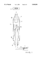
FIG. 1 is a schematic view showing an elemental analysis apparatus according to the present invention;
FIG. 2 is a schematic view showing another elemental analysis apparatus according to the present invention;
FIG. 3 is a graph showing the difference between a normal turbulent flow and a spiral flow in a torch of the present invention;
FIG. 4 is a view showing the actual state of a conventional plasma torch;
FIG. 5 is a view showing the actual state of the plasma torch of the present invention;
FIG. 6 is a graph showing a phosphorus analysis result using a mass spectrometer using the conventional torch; and
FIG. 7 is a graph showing a phosphorus analysis result using a mass spectrometer using the torch of the present invention.
FIG. 1 shows the main part of an atomic absorption spectrochemical analysis apparatus using spiral flow ICP.
As shown in FIG. 1, a sample solution in a sample supply unit 1 is supplied to a tube 2a of a plasma torch 2 through a sample tube 1a.
This silica glass plasma torch 2 has a triple structure. Ar gas is supplied from a cooling gas system 2b and an auxiliary gas system 2c so as to surround the sample supply tube 2a.
A plasma chamber 2d of the plasma torch 2 has a conical cylinder. In addition, an RF addition cold coil 3 is wound on the plasma chamber 2d. When an RF power (27.12 MHz) is applied from the cold coil 3 to the plasma chamber 2d while Ar is kept supplied to the plasma chamber 2d, a plasma 4 is generated in the plasma chamber 2d.
Ar supplied from the cooling gas system 2b is consumed as a plasma source in the plasma chamber 2d while cooling the outer wall of the plasma torch 2.
Ar supplied from the auxiliary gas system 2c is supplied to push up the plasma 4 generated in the plasma chamber 2d so as not to drop the plasma 4 to the distal end portion of the sample supply tube 2a. In addition, this Ar gas is supplied from a portion near the distal end of the sample supply tube 2a, so that the sample solution is evaporated and the sample gas is supplied from the distal end of the sample supply tube 2a to the plasma chamber 2d.
The vapor of the sample solution is supplied to the plasma chamber 2d in which the plasma 4 is generated upon application of an RF power. The sample supplied to the plasma 4 is ionized by the plasma 4. The outer diameter of the plasma torch 2 is 20 mm, the diameter d of a nozzle at the distal end of the plasma torch 2 is 11 mm, and the taper angle θ of the torch portion is 13°.
The emission or absorption spectrum of the sample ionized in the plasma 4 is detected by a detector 5 to analyze the ions.
FIG. 2 shows the main part of a mass spectrometer using the ICP according to the present invention. In this mass spectroscopy, a sample ionized in a plasma chamber 2d of a plasma torch 2 and emitted from the plasma torch 2 is deflected in a magnetic field from a separator 6. The deflected ionized sample reaches a mass spectrometer 7 comprised of a Faraday cup and is detected by this mass spectrometer 7. In this mass spectrometer, the outer diameter of the plasma torch 2 is 20 mm, the diameter of a nozzle at the distal end of the plasma torch 2 is 11 mm, and the taper angle θ of the distal end portion is 13°.
Unlike in this embodiment, in a conventional plasma torch whose distal end is not tapered, supply ports of cooling and auxiliary gases are offset from the center, thus providing a structure with a certain rotating component. That is, a turbulent flow is generated in a conventional torch, but does not produce a satisfactorily focused plasma flame.
Even if the outlet port of a torch is simply tapered, a focused plasma flame cannot be obtained. This simply tapered outlet port increases a pressure loss and fails to assure a static pressure. Therefore, a gas tends not to flow and cannot be focused.
To the contrary, in this embodiment, the conical cylinder of the plasma torch 2 is tapered into a given shape (conical shape). When a gas is supplied, it becomes a spiral flow. The spiral flow produces a stable plasma flame upon application of an RF power to the spiral flow.
The given shape is obtained by setting the Reynolds number (SRe) to -6 or less in the radial direction of the gas flow.
The Reynolds number SRe is defined as SRe =Vr R/γR where VR is the function Vr =f(Vza, θ) between the average axial velocity Vza and the taper angle θ at the conical cylinder of the torch, and γR is the kinematic viscosity. The diameter of the distal end portion of the torch is defined as d=2R.
A spiral flow is apparently generated when the Reynolds number is -6 or less. More specifically, when the diameter of the distal end portion of the torch is 0.1 to 100 mm, and the taper angle of the distal end portion of the torch falls within the range of 5° to 60°, a spiral flow is generated.
FIG. 3 shows the difference between a normal turbulent flow and the spiral flow obtained by the torch of this embodiment. The Reynolds numbers of the turbulent flow and the spiral flow for a swirl number of 0.3 are plotted along the abscissa of FIG. 3, and the half widths of the plasma flame spreads are plotted along the ordinate of FIG. 3.
As can be apparent from FIG. 3, the half width of the plasma flame spread abruptly decreases near |6| of the Reynolds number to obtain a spiral flow, thereby focusing the plasma flame.
As described above, the same sample supply amount is set for the conventional torch and the above-described spiral flow torch of the present invention, the concentrations of impurities, i.e., sample elements to be detected, except for Ar contained in the plasma flame are increased by a focused component.
When the diameter of an area where the focused plasma flame can be detected is much smaller than the outer diameter of the plasma flame, the above effect can be greatly enhanced. For example, when the diameter of the area where the plasma flame can be detected is set 1/2 the outer diameter of the plasma flame, the impurity concentration increases four times, so that the sensitivity increases four times. When the diameter of the area where the plasma flame can be detected is set 1/3 the outer diameter of the plasma flame, the impurity concentration becomes nine times. Therefore, the sensitivity becomes nine times accordingly, and the sensitivity increases by about one order of magnitude.
The spiral flow is as close as a laminar flow and is almost free from a pulsating flow. The spiral flow also has a strong directivity, so that a stable flame almost free from fluctuations can be obtained. For this reason, the impurity and plasma profiles can be obtained with good repeatability, and the repetition accuracy can be improved.
FIGS. 4 and 5 show the states of plasmas obtained by the conventional plasma torch and the plasma torch of the present invention, respectively.
A 27.12-MHz RF power having an output of 1 kW was applied to the plasma chamber of each torch, and a sample flow was supplied at a flow rate of 0.55 (l/min). Ar was supplied as a cooling gas at a flow rate of 15 (l/min), and Ar is supplied as auxiliary gas at a flow rate of 0.5 (l/min).
As shown in FIG. 4, a plasma flame is not focused in the conventional plasma torch. As shown in FIG. 5, however, a plasma flame is focused in the plasma torch of the present invention.
Consequently, in the elemental analysis apparatuses shown in FIGS. 1 and 2 and the elemental analysis method using such an apparatus, since the sample flow becomes a spiral flow in the plasma torch, the focused plasma flame can be obtained. As a result, an element contained in a sample in a very small amount can be analyzed with a high sensitivity.
As the central portion of the plasma flame of the spiral flow has a high flow velocity, the plasma flame does not almost interact with the tube wall of the torch. As shown in FIG. 5, the plasma flame will not directly contact the tube wall of the torch. The plasma flame does not melt the torch, and the analysis sensitivity and accuracy are not adversely affected by contamination caused by chemical reactions between the torch and the sample components.
Since a stable plasma flame almost free from fluctuations can be obtained according to the present invention, elemental analysis can be performed with a high accuracy.
For example, when a 10 ppm lanthanum solution was subjected to mass spectroscopy using a conventional plasma torch at a sample flow rate of 1.0 (l/min) under the conditions that an RF output having a frequency of 27.12 MHz was set to 1.4 kW, a cooling gas flow rate was set to 12.0 (l/min), and auxiliary gas flow rate was set to 0.5 (l/min), the intensity of 139 La was counted as 7.4×10¹⁰ in a Farady cup (detector) measurement.
To the contrary, under the same conditions as described above, in the analysis in the mass spectrometer (FIG. 2) using the plasma torch of the present invention, the intensity of 139 La was counted as 1.6×10¹¹, thus improving the sensitivity to about twice that of the conventional analysis.
As the repeatability in 10 measurements, the relative standard deviation (RSD) in the analysis using the conventional plasma torch was 4.04%. However, in the analysis using the plasma torch of the present invention, the relative standard deviation was 1.04%, which greatly improved the accuracy. In addition, since the plasma flame is surrounded by the gases at the distal end portion of the torch, sensitivity and accuracy degradations caused by interference of components in the air can be prevented.
A phosphorus analysis will be described below. FIG. 6 shows a phosphorus analysis result in a mass spectrometer using the conventional torch, while FIG. 7 shows a phosphorus analysis result in a mass spectrometer using the torch of the present invention.
The concentration of a phosphorus sample to be analyzed is 10 ppb, and the analysis resolution is set to 3,000 or more.
As shown in FIG. 6, in the mass spectroscopy of 31 P using an ICP, 15 N16 O and 14 N16 O1 H are interference ions.
As shown in FIG. 7, when the torch of the present invention is used, the 31 P detection peak height becomes almost doubled. No changes occur in the detection peak heights of 15 N16 O and 14 N16 O1 H as interference ions. That is, as is apparent, the influence of the interference ions can be relatively halved by using the torch of the present invention.
As has been described above, the elemental analysis method and apparatus of the present invention use a torch in which the outlet port for emitting a generated plasma is conical cylinder with a given taper angle.
With this structure, a sample flow becomes a spiral flow to focus a plasma flame in an area of the torch where the plasma is generated.
According to the present invention, elemental analysis can be performed with a high sensitivity. At the same time, since a stable flame almost free from fluctuations can be obtained, elemental analysis can be performed with a high accuracy.
Claims (7)
1. An elemental analysis method of analyzing a sample as an analysis target using atoms generated upon dissociation of the sample, comprising:
generating a plasma using a gas serving as a plasma source to be supplied in a torch having a conical cylindrical section thereof;
supplying to the plasma a sample flow obtained by evaporating the sample using the gas as a carrier gas or a sample flow containing a component of the sample;
reforming the sample flow or the plasma containing the sample flow into a spiral flow and dissociating the component of the sample; and analyzing the sample in accordance with a state of an atom generated by dissociation of the component of the sample.
2. An elemental analysis apparatus for analyzing a sample as an analysis target using atoms generated upon dissociation of the sample, comprising:
a torch having a coil for applying an RF power to an ambient atmosphere, a plasma chamber for generating a plasma using the RF power and dissociating the sample, and a conical cylindrical section with a given taper angle to emit the generated plasma;
a sample supply unit for delivering a sample solution toward said plasma chamber;
an auxiliary gas supply unit for delivering an auxiliary gas serving as a plasma source from a peripheral portion of said sample supply unit to said plasma chamber to evaporate the sample solution delivered from said sample supply unit;
a main gas supply unit for delivering a main gas serving as a plasma source from a peripheral portion of said torch to said plasma chamber to cool a wall surface of said torch; and
a detector arranged at an emission destination of the plasma in said torch to detect a state of an atom of the sample dissociated by the plasma.
3. An apparatus according to claim 2, wherein said detector comprises photodetecting means for detecting optical characteristics of the atom in the plasma emitted from said torch.
4. An apparatus according to claim 2, wherein said detector comprises:
a separator disposed immediately after said torch; and
an ion detector for detecting the atom emitted from said torch and passed through said separator.
5. An apparatus according to claim 2, wherein the taper angle is an angle defined such that the Reynolds number of said conical cylindrical section of said torch is not more than -6.
6. An apparatus according to claim 5, wherein said detector comprises photodetecting means for detecting optical characteristics of the atom in the plasma emitted from said torch.
7. An apparatus according to claim 5, wherein said detector comprises:
a separator disposed immediately after said torch; and
an ion detector for detecting the atom emitted from said torch and passed through said separator.
Applications Claiming Priority (2)
| Application Number | Priority Date | Filing Date | Title |
|---|---|---|---|
| JP34034595 | 1995-12-27 | ||
| JP7-340345 | 1995-12-27 |
Publications (1)
| Publication Number | Publication Date |
|---|---|
| US5818581A true US5818581A (en) | 1998-10-06 |
Family
ID=18336054
Family Applications (1)
| Application Number | Title | Priority Date | Filing Date |
|---|---|---|---|
| US08/774,837 Expired - Lifetime US5818581A (en) | 1995-12-27 | 1996-12-27 | Elemental analysis method and apparatus |
Country Status (2)
| Country | Link |
|---|---|
| US (1) | US5818581A (en) |
| EP (1) | EP0792091B1 (en) |
Cited By (19)
| Publication number | Priority date | Publication date | Assignee | Title |
|---|---|---|---|---|
| US6063731A (en) * | 1999-03-30 | 2000-05-16 | Agritope, Inc. | Brassinosteroid analogs useful as plant growth regulators |
| WO2004055493A2 (en) * | 2002-12-12 | 2004-07-01 | Perkinelmer Las, Inc. | Icp-oes and icp-ms induction current |
| US20040183008A1 (en) * | 2001-07-03 | 2004-09-23 | Wiseman Alan G | Plasma torch |
| US20060038992A1 (en) * | 2002-12-12 | 2006-02-23 | Perkinelmer, Inc. | Induction device for generating a plasma |
| US20060286492A1 (en) * | 2005-06-17 | 2006-12-21 | Perkinelmer, Inc. | Boost devices and methods of using them |
| US20060285108A1 (en) * | 2005-06-17 | 2006-12-21 | Perkinelmer, Inc. | Optical emission device with boost device |
| US20070075051A1 (en) * | 2005-03-11 | 2007-04-05 | Perkinelmer, Inc. | Plasmas and methods of using them |
| US20070284242A1 (en) * | 2004-01-06 | 2007-12-13 | Michel Moisan | Method For Treating Gases By High Frequency Discharges |
| US20090095901A1 (en) * | 2007-10-10 | 2009-04-16 | Mks Instruments, Inc. | Chemical ionization reaction or proton transfer reaction mass spectrometry with a quadrupole mass spectrometer |
| US8222822B2 (en) | 2009-10-27 | 2012-07-17 | Tyco Healthcare Group Lp | Inductively-coupled plasma device |
| US8575843B2 (en) | 2008-05-30 | 2013-11-05 | Colorado State University Research Foundation | System, method and apparatus for generating plasma |
| US20150060418A1 (en) * | 2010-05-05 | 2015-03-05 | Perkinelmer Health Sciences, Inc. | Inductive devices and low flow plasmas using them |
| US8994270B2 (en) | 2008-05-30 | 2015-03-31 | Colorado State University Research Foundation | System and methods for plasma application |
| US9028656B2 (en) | 2008-05-30 | 2015-05-12 | Colorado State University Research Foundation | Liquid-gas interface plasma device |
| US9259798B2 (en) | 2012-07-13 | 2016-02-16 | Perkinelmer Health Sciences, Inc. | Torches and methods of using them |
| US9272359B2 (en) | 2008-05-30 | 2016-03-01 | Colorado State University Research Foundation | Liquid-gas interface plasma device |
| US9288886B2 (en) | 2008-05-30 | 2016-03-15 | Colorado State University Research Foundation | Plasma-based chemical source device and method of use thereof |
| US9532826B2 (en) | 2013-03-06 | 2017-01-03 | Covidien Lp | System and method for sinus surgery |
| US9555145B2 (en) | 2013-03-13 | 2017-01-31 | Covidien Lp | System and method for biofilm remediation |
Families Citing this family (13)
| Publication number | Priority date | Publication date | Assignee | Title |
|---|---|---|---|---|
| US6308654B1 (en) * | 1996-10-18 | 2001-10-30 | Applied Materials, Inc. | Inductively coupled parallel-plate plasma reactor with a conical dome |
| NO304861B1 (en) * | 1997-02-14 | 1999-02-22 | Cato Brede | Method of Element Selective Detection, Microplasma Mass Spectrometer for Use in the Method and Plasma Ion Source, and Applications of These |
| AU2002244508B2 (en) * | 2001-07-03 | 2006-07-27 | Agilent Technologies Australia (M) Pty Ltd | Plasma torch |
| DE102009006016A1 (en) | 2009-01-23 | 2010-07-29 | Plasma Treat Gmbh | Method and device for the detection of ionizable gases, in particular organic molecules, preferably hydrocarbons |
| WO2018202827A1 (en) * | 2017-05-04 | 2018-11-08 | Umicore Ag & Co. Kg | Plasma gun and plasma system for low melting point or low boiling point materials |
| GB201808912D0 (en) | 2018-05-31 | 2018-07-18 | Micromass Ltd | Bench-top time of flight mass spectrometer |
| GB201808892D0 (en) | 2018-05-31 | 2018-07-18 | Micromass Ltd | Mass spectrometer |
| US11367607B2 (en) | 2018-05-31 | 2022-06-21 | Micromass Uk Limited | Mass spectrometer |
| GB201808890D0 (en) | 2018-05-31 | 2018-07-18 | Micromass Ltd | Bench-top time of flight mass spectrometer |
| GB201808894D0 (en) | 2018-05-31 | 2018-07-18 | Micromass Ltd | Mass spectrometer |
| WO2019229463A1 (en) | 2018-05-31 | 2019-12-05 | Micromass Uk Limited | Mass spectrometer having fragmentation region |
| GB201808949D0 (en) | 2018-05-31 | 2018-07-18 | Micromass Ltd | Bench-top time of flight mass spectrometer |
| GB201808936D0 (en) | 2018-05-31 | 2018-07-18 | Micromass Ltd | Bench-top time of flight mass spectrometer |
Citations (7)
| Publication number | Priority date | Publication date | Assignee | Title |
|---|---|---|---|---|
| US4266113A (en) * | 1979-07-02 | 1981-05-05 | The United States Of America As Represented By The Secretary Of The Navy | Dismountable inductively-coupled plasma torch apparatus |
| US4551609A (en) * | 1983-03-24 | 1985-11-05 | Siemens Aktiengesellschaft | Spectrometry plasma burner |
| GB2180957A (en) * | 1985-09-09 | 1987-04-08 | Kiyoshi Horii | Fluid flow generator |
| US4818916A (en) * | 1987-03-06 | 1989-04-04 | The Perkin-Elmer Corporation | Power system for inductively coupled plasma torch |
| EP0335448A1 (en) * | 1988-03-28 | 1989-10-04 | Koninklijke Philips Electronics N.V. | Plasma torch |
| EP0397468A2 (en) * | 1989-05-09 | 1990-11-14 | Varian Associates, Inc. | Spectroscopic plasma torch for microwave induced plasmas |
| JPH0426099A (en) * | 1990-05-21 | 1992-01-29 | Hitachi Ltd | Torch for high frequency plasma and element analysis apparatus using the same |
-
1996
- 1996-12-26 EP EP96390014A patent/EP0792091B1/en not_active Expired - Lifetime
- 1996-12-27 US US08/774,837 patent/US5818581A/en not_active Expired - Lifetime
Patent Citations (8)
| Publication number | Priority date | Publication date | Assignee | Title |
|---|---|---|---|---|
| US4266113A (en) * | 1979-07-02 | 1981-05-05 | The United States Of America As Represented By The Secretary Of The Navy | Dismountable inductively-coupled plasma torch apparatus |
| US4551609A (en) * | 1983-03-24 | 1985-11-05 | Siemens Aktiengesellschaft | Spectrometry plasma burner |
| GB2180957A (en) * | 1985-09-09 | 1987-04-08 | Kiyoshi Horii | Fluid flow generator |
| US4721126A (en) * | 1985-09-09 | 1988-01-26 | Kiyoshi Horii | Method of generating spiral fluid flow and the device therefor |
| US4818916A (en) * | 1987-03-06 | 1989-04-04 | The Perkin-Elmer Corporation | Power system for inductively coupled plasma torch |
| EP0335448A1 (en) * | 1988-03-28 | 1989-10-04 | Koninklijke Philips Electronics N.V. | Plasma torch |
| EP0397468A2 (en) * | 1989-05-09 | 1990-11-14 | Varian Associates, Inc. | Spectroscopic plasma torch for microwave induced plasmas |
| JPH0426099A (en) * | 1990-05-21 | 1992-01-29 | Hitachi Ltd | Torch for high frequency plasma and element analysis apparatus using the same |
Non-Patent Citations (4)
| Title |
|---|
| J.C. Eames et al., "Practical Design for an ICP Demountable Plasma Torch", 1369 Applied Spectroscopy 46 (1992), N. 11, pp. 1745-1746. |
| J.C. Eames et al., Practical Design for an ICP Demountable Plasma Torch , 1369 Applied Spectroscopy 46 (1992), N. 11, pp. 1745 1746. * |
| Thomas R. Smith et al., "A High-Pressure Inductively Coupled Plasma Torch", 1369 Applied Spectroscopy 41 (1987) May/Jun., No. 4, pp. 654-657. |
| Thomas R. Smith et al., A High Pressure Inductively Coupled Plasma Torch , 1369 Applied Spectroscopy 41 (1987) May/Jun., No. 4, pp. 654 657. * |
Cited By (53)
| Publication number | Priority date | Publication date | Assignee | Title |
|---|---|---|---|---|
| US6063731A (en) * | 1999-03-30 | 2000-05-16 | Agritope, Inc. | Brassinosteroid analogs useful as plant growth regulators |
| US20040183008A1 (en) * | 2001-07-03 | 2004-09-23 | Wiseman Alan G | Plasma torch |
| US6989529B2 (en) * | 2001-07-03 | 2006-01-24 | Varian Australia Pty Ltd. | Plasma torch |
| US7106438B2 (en) | 2002-12-12 | 2006-09-12 | Perkinelmer Las, Inc. | ICP-OES and ICP-MS induction current |
| US20150085280A1 (en) * | 2002-12-12 | 2015-03-26 | Perkinelmer Health Sciences, Inc. | Induction device |
| WO2004055493A3 (en) * | 2002-12-12 | 2004-12-09 | Perkinelmer Las Inc | Icp-oes and icp-ms induction current |
| AU2003293514B8 (en) * | 2002-12-12 | 2004-07-09 | Perkinelmer U.S. Llc | A spectroscopic system and method of spectroscopically analysing a material sample |
| US20060038992A1 (en) * | 2002-12-12 | 2006-02-23 | Perkinelmer, Inc. | Induction device for generating a plasma |
| US20090166179A1 (en) * | 2002-12-12 | 2009-07-02 | Peter Morrisroe | Induction Device |
| US9360430B2 (en) * | 2002-12-12 | 2016-06-07 | Perkinelmer Health Services, Inc. | Induction device |
| US20040169855A1 (en) * | 2002-12-12 | 2004-09-02 | Morrisroe Peter J. | ICP-OES and ICP-MS induction current |
| US8742283B2 (en) * | 2002-12-12 | 2014-06-03 | Perkinelmer Health Sciences, Inc. | Induction device |
| AU2003293514B2 (en) * | 2002-12-12 | 2007-07-19 | Perkinelmer U.S. Llc | A spectroscopic system and method of spectroscopically analysing a material sample |
| WO2004055493A2 (en) * | 2002-12-12 | 2004-07-01 | Perkinelmer Las, Inc. | Icp-oes and icp-ms induction current |
| US20120325783A1 (en) * | 2002-12-12 | 2012-12-27 | Peter Morrisroe | Induction device |
| US7511246B2 (en) | 2002-12-12 | 2009-03-31 | Perkinelmer Las Inc. | Induction device for generating a plasma |
| US8263897B2 (en) | 2002-12-12 | 2012-09-11 | Perkinelmer Health Sciences, Inc. | Induction device |
| CN100529741C (en) * | 2002-12-12 | 2009-08-19 | 珀金埃尔默Las公司 | ICP-OES and ICP-MS induction current |
| US20070284242A1 (en) * | 2004-01-06 | 2007-12-13 | Michel Moisan | Method For Treating Gases By High Frequency Discharges |
| US8633416B2 (en) | 2005-03-11 | 2014-01-21 | Perkinelmer Health Sciences, Inc. | Plasmas and methods of using them |
| US10368427B2 (en) * | 2005-03-11 | 2019-07-30 | Perkinelmer Health Sciences, Inc. | Plasmas and methods of using them |
| US20140224984A1 (en) * | 2005-03-11 | 2014-08-14 | Peter J. Morrisroe | Plasmas and methods of using them |
| US20070075051A1 (en) * | 2005-03-11 | 2007-04-05 | Perkinelmer, Inc. | Plasmas and methods of using them |
| US8896830B2 (en) | 2005-06-17 | 2014-11-25 | Perkinelmer Health Sciences, Inc. | Devices and systems including a boost device |
| US7742167B2 (en) * | 2005-06-17 | 2010-06-22 | Perkinelmer Health Sciences, Inc. | Optical emission device with boost device |
| US7737397B2 (en) | 2005-06-17 | 2010-06-15 | Perkinelmer Health Sciences, Inc. | Devices and systems including a boost device |
| US8289512B2 (en) | 2005-06-17 | 2012-10-16 | Perkinelmer Health Sciences, Inc. | Devices and systems including a boost device |
| US20080173810A1 (en) * | 2005-06-17 | 2008-07-24 | Perkinelmer, Inc. | Devices and systems including a boost device |
| US9847217B2 (en) | 2005-06-17 | 2017-12-19 | Perkinelmer Health Sciences, Inc. | Devices and systems including a boost device |
| US8622735B2 (en) * | 2005-06-17 | 2014-01-07 | Perkinelmer Health Sciences, Inc. | Boost devices and methods of using them |
| US20060286492A1 (en) * | 2005-06-17 | 2006-12-21 | Perkinelmer, Inc. | Boost devices and methods of using them |
| US20060285108A1 (en) * | 2005-06-17 | 2006-12-21 | Perkinelmer, Inc. | Optical emission device with boost device |
| US20100320379A1 (en) * | 2005-06-17 | 2010-12-23 | Peter Morrisroe | Devices and systems including a boost device |
| KR101386017B1 (en) | 2005-09-02 | 2014-04-16 | 퍼킨엘머, 인크. | Induction device for generating a plasma |
| WO2007027784A3 (en) * | 2005-09-02 | 2009-04-16 | Perkinelmer Inc | Induction device for generating a plasma |
| CN101500741B (en) * | 2005-09-02 | 2017-07-28 | 魄金莱默有限公司 | Generate the induction installation of plasma |
| US8003935B2 (en) * | 2007-10-10 | 2011-08-23 | Mks Instruments, Inc. | Chemical ionization reaction or proton transfer reaction mass spectrometry with a quadrupole mass spectrometer |
| US20090095901A1 (en) * | 2007-10-10 | 2009-04-16 | Mks Instruments, Inc. | Chemical ionization reaction or proton transfer reaction mass spectrometry with a quadrupole mass spectrometer |
| US9272359B2 (en) | 2008-05-30 | 2016-03-01 | Colorado State University Research Foundation | Liquid-gas interface plasma device |
| US9288886B2 (en) | 2008-05-30 | 2016-03-15 | Colorado State University Research Foundation | Plasma-based chemical source device and method of use thereof |
| US8575843B2 (en) | 2008-05-30 | 2013-11-05 | Colorado State University Research Foundation | System, method and apparatus for generating plasma |
| US8994270B2 (en) | 2008-05-30 | 2015-03-31 | Colorado State University Research Foundation | System and methods for plasma application |
| US9028656B2 (en) | 2008-05-30 | 2015-05-12 | Colorado State University Research Foundation | Liquid-gas interface plasma device |
| US9287091B2 (en) | 2008-05-30 | 2016-03-15 | Colorado State University Research Foundation | System and methods for plasma application |
| US8878434B2 (en) | 2009-10-27 | 2014-11-04 | Covidien Lp | Inductively-coupled plasma device |
| US8222822B2 (en) | 2009-10-27 | 2012-07-17 | Tyco Healthcare Group Lp | Inductively-coupled plasma device |
| US9198275B2 (en) * | 2010-05-05 | 2015-11-24 | Perkinelmer Health Sciences, Inc. | Inductive devices and low flow plasmas using them |
| US20150060418A1 (en) * | 2010-05-05 | 2015-03-05 | Perkinelmer Health Sciences, Inc. | Inductive devices and low flow plasmas using them |
| US9259798B2 (en) | 2012-07-13 | 2016-02-16 | Perkinelmer Health Sciences, Inc. | Torches and methods of using them |
| US9686849B2 (en) | 2012-07-13 | 2017-06-20 | Perkinelmer Health Sciences, Inc. | Torches and methods of using them |
| US9532826B2 (en) | 2013-03-06 | 2017-01-03 | Covidien Lp | System and method for sinus surgery |
| US10524848B2 (en) | 2013-03-06 | 2020-01-07 | Covidien Lp | System and method for sinus surgery |
| US9555145B2 (en) | 2013-03-13 | 2017-01-31 | Covidien Lp | System and method for biofilm remediation |
Also Published As
| Publication number | Publication date |
|---|---|
| EP0792091B1 (en) | 2002-03-13 |
| EP0792091A1 (en) | 1997-08-27 |
Similar Documents
| Publication | Publication Date | Title |
|---|---|---|
| US5818581A (en) | Elemental analysis method and apparatus | |
| Okamoto | Annular-shaped microwave-induced nitrogen plasma at atmospheric pressure for emission spectrometry of solutions | |
| Shigeta et al. | Application of a micro-droplet generator for an ICP-sector field mass spectrometer–optimization and analytical characterization | |
| Brenner et al. | Axially and radially viewed inductively coupled plasmas—a critical review | |
| US6166379A (en) | Direct injection high efficiency nebulizer for analytical spectrometry | |
| US8822948B1 (en) | Method and apparatus for control of a plasma for spectrometry | |
| US20080272285A1 (en) | Ion Mobility Spectrometer Comprising a Corona Discharge Ionization Element | |
| US5477048A (en) | Inductively coupled plasma mass spectrometer | |
| US9784714B2 (en) | Discharge ionization current detector and tuning method for the same | |
| US7145137B2 (en) | Demountable direct injection high efficiency nebulizer for inductively coupled plasma mass spectrometry | |
| US5252827A (en) | Method and apparatus for analysis of gases using plasma | |
| Robin | ICP-AES at the beginning of the eighties | |
| Kaneco et al. | Optimization of operating conditions in individual airborne particle analysis by inductively coupled plasma mass spectrometry | |
| EP0015284B1 (en) | Flameless emission spectroscope apparatus and sample introduction method for same | |
| US6236012B1 (en) | Plasma torch with an adjustable injector and gas analyzer using such a torch | |
| US20020001540A1 (en) | ICP analyzer | |
| JP4095646B2 (en) | Elemental analyzer | |
| Houk et al. | Atomic emission spectrometry with a reduced-pressure afterglow extracted from an inductively coupled plasma | |
| Koropchak et al. | Aerosol particle size effects on plasma spectrometric analysis | |
| US5731872A (en) | Plasma manipulator | |
| JPH09318542A (en) | Method and apparatus for analyzing element | |
| JPH0426099A (en) | Torch for high frequency plasma and element analysis apparatus using the same | |
| Ciopec et al. | Inductively Coupled Plasma Optical Spectroscopy and Atomic Absorption Spectroscopy | |
| Schlemmer et al. | AAS: a simple and rugged system for trace and ultratrace elemental analysis | |
| JPS6296850A (en) | Furnace plasma light emission analyzer |
Legal Events
| Date | Code | Title | Description |
|---|---|---|---|
| AS | Assignment |
Owner name: NIPPON TELEGRAPH AND TELEPHONE CORPORATION, JAPAN Free format text: ASSIGNMENT OF ASSIGNORS INTEREST;ASSIGNORS:KUROSAWA, SATORU;ISHII, YOSHIKAZU;HORI, KIYOSHI;REEL/FRAME:008379/0418 Effective date: 19961216 |
|
| STCF | Information on status: patent grant |
Free format text: PATENTED CASE |
|
| FPAY | Fee payment |
Year of fee payment: 4 |
|
| FPAY | Fee payment |
Year of fee payment: 8 |
|
| FPAY | Fee payment |
Year of fee payment: 12 |