US5817243A - Method for applying decorative contrast designs to automotive and motorcycle parts using lasers - Google Patents
Method for applying decorative contrast designs to automotive and motorcycle parts using lasers Download PDFInfo
- Publication number
- US5817243A US5817243A US08/740,443 US74044396A US5817243A US 5817243 A US5817243 A US 5817243A US 74044396 A US74044396 A US 74044396A US 5817243 A US5817243 A US 5817243A
- Authority
- US
- United States
- Prior art keywords
- laser
- decorative
- design
- computer
- scanning
- Prior art date
- Legal status (The legal status is an assumption and is not a legal conclusion. Google has not performed a legal analysis and makes no representation as to the accuracy of the status listed.)
- Expired - Fee Related
Links
Images
Classifications
-
- B—PERFORMING OPERATIONS; TRANSPORTING
- B44—DECORATIVE ARTS
- B44C—PRODUCING DECORATIVE EFFECTS; MOSAICS; TARSIA WORK; PAPERHANGING
- B44C1/00—Processes, not specifically provided for elsewhere, for producing decorative surface effects
- B44C1/22—Removing surface-material, e.g. by engraving, by etching
- B44C1/228—Removing surface-material, e.g. by engraving, by etching by laser radiation
-
- B—PERFORMING OPERATIONS; TRANSPORTING
- B60—VEHICLES IN GENERAL
- B60R—VEHICLES, VEHICLE FITTINGS, OR VEHICLE PARTS, NOT OTHERWISE PROVIDED FOR
- B60R13/00—Elements for body-finishing, identifying, or decorating; Arrangements or adaptations for advertising purposes
Definitions
- the present invention relates to the field of decorating plastic, glass, metals and leather, and more particularly methods for transferring decorative contrast designs to motorcycle and automotive parts using a laser.
- Lasers have been used in automated assembly lines for cutting, heating and curing applications.
- the use of lasers to mark indicia into plastic parts, such as contact lenses for identification and orientation purposes is known.
- surface markings are designed to be small and unobtrusive to the eye when the product is in use.
- a method comprising use of a laser to permanently etch a complex, well-contrasted computer-programmed design into a glass, metal, plated metal or plastic automotive or motorcycle part is not known.
- the present invention relates to a method for permanently decorating motorcycle and automobile parts, wherein a part is provided along with a programmable computer-controlled laser assembly capable of emitting a beam.
- the computer acquires a desired image, such as by scanning the image.
- the computer is programmed to control the pulse rate and X-Y movement of the laser beam across the part surface to effect a desired design on the part.
- the beam is then directed and scanned over the part, with the programmed design permanently transferred to the part.
- a further embodiment of the present invention relates to a method for creating a decorative contrast design on motorcycle and automobile parts by providing a metal or metal-plated motorcycle or automobile part having a surface, and a programmable computer-controlled laser assembly capable of emitting and scanning a laser beam having a desired fluence.
- Data representing a decorative contrast design is stored in the computer as the design is acquired into the system.
- the laser fluence is adjusted to remove a desired amount of material per pulse from the part surface, and the scanning rate is selected and input into the computer.
- the computer is then programmed to pulse and orient the laser in a specified position to effect a reproducible desired decorative contrast design on the part surface.
- the laser is turned on and the beam is directed to, and scanned over the part surface, transferring the programmed decorative contrast design into the part leaving etched and unetched portions on the part surface.
- the part comprises a metal or metal plating or coating
- the part is then reacted with an oxidizing agent to increase the contrast of the decorative design between the etched and unetched part surfaces.
- a still further embodiment of the present invention relates to a method for creating a decorative contrast design on plastic motorcycle and automobile parts by providing a plastic motorcycle or automobile part and a programmable computer-controlled laser assembly capable of emitting and scanning a laser beam having a desired fluence.
- Data representing a decorative contrast design is stored in the computer as the design is acquired into the system.
- the laser fluence is adjusted to cause a discoloration of the plastic and create an image within the translucent or transparent plastic globes and lenses.
- the scanning rate is selected and input into the computer.
- the computer is then programmed to pulse and orient the laser in a specified position to effect a reproducible desired decorative contrast design in the part.
- the laser is turned on and the beam is directed to, and scanned over the part surface, transferring the programmed decorative contrast design into the part. Alternatively, the beam may also be scanned across the surface to etch the design into the part surface.
- Another embodiment of the present invention relates to a method for creating a decorative contrast design on mirrored motorcycle and automobile parts by providing a mirror, and a programmable computer-controlled laser assembly capable of emitting and scanning a laser beam having a desired fluence.
- Data representing a decorative contrast design is stored in the computer as the design is acquired into the system.
- the laser fluence is adjusted to remove a desired amount of material per pulse from the front or coated back surface of the mirror, and the scanning rate is selected and input into the computer.
- the computer is then programmed to pulse and orient the laser in a specified position to effect a reproducible desired decorative contrast design on the part surface.
- the laser is turned on and the beam is directed to, and scanned over the part surface, transferring the programmed decorative contrast design into the part leaving etched and unetched portions on the part surface.
- the mirrored part is then optionally coated with a paint or holographic coating to increase the perceived contrast of the decorative design between the etched and unetched surfaces.
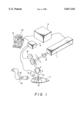
- FIG. 1 is a schematic representation of the system of the present invention.
- FIG. 1 shows a schematic representation of the system of the present invention.
- a laser 1 having an acousto-optic modulator 2 is attached to a laser power supply 3.
- a computer 5 is connected to the laser scanner drivers 4 and X-axis galvanometer scanner 8 and Y-axis galvanometer scanner 9.
- Beam 10 is emitted from the laser 1 and directed through beam expander 6 and focusing lens 7.
- the beam is then redirected by the X-axis scanner 8 having mirror 8a and Y-axis scanner 9 having mirror 9a.
- the beam then impacts the part 11, etching the permanent decorative contrast design 12 into the part 11.
- Blower motor with fan 14 inside vent assembly 16 creates a vacuum which removes debris from the environment surrounding the part surface.
- the first step in the process of the present invention is to acquire the decorative image to be transferred to the automotive or motorcycle part.
- the desired image or design to be transferred is initially provided to the screen of a flatbed scanner.
- the image may also be, for example, the result of a digital photograph stored on a photo CD, or the product of a CAD (computer aided program), or a commercially available computer drawing program.
- the image may be processed by either raster images or vector images.
- Raster images are images made up of picture elements (dots) or pixels. These images include most photographic and drawing program images.
- the image size be scaled to match the desired resolution of the final image on the part.
- the image color depth (number of colors) must be reduced to only two levels: black and white.
- the black will preferably correspond to a "laser on” pulse mode and the white will correspond to a "laser off” pulse mode.
- the processed image should then be saved as either a BMP (bitmap) or PCX file format (e.g. Microsoft PaintbrushTM) for image file conversion.
- BMP bitmap
- PCX file format e.g. Microsoft PaintbrushTM
- Vector images are line images such as, for example, those generated in CAD programs.
- Vectors in the CAD program have a start coordinate, a stop coordinate, and a corresponding angle.
- Each line of the design to be transferred to the part in vector mode has a start position corresponding with the start coordinate in the CAD program, a stop position corresponding with the stop coordinate in the CAD program and an angle also coordinated with the CAD program.
- Each line or vector in the vector mode is preferably one laser scan in the laser etched image on the part.
- Vector images are preferably saved as a PLT (plot file) file format which is accepted by the selected laser control program (e.g. ProlaseTM, American Laserware, Inc., Orlando, Fla.).
- the acquired image must undergo file conversion to enable the computer system to direct the laser to scan the image onto the part surface.
- file conversion includes: 1) a BMP (bitmap) to PLT (plot file) conversion; 2) PLT (plot file) being directly read by computer control system (CCS) (e.g. ProlaseTM); and 3) PCX directly read by the CCS (e.g. ProlaseTM).
- CCS computer control system
- PCX directly read by the CCS
- PLT is the extension and file format for the HP plotter.
- PXC is the extension and file format for the program PC PaintbrushTM.
- the image can then be manipulated relative to size and orientation requirements. The user can adjust image height, width and image rotation with respect to the marking field.
- the CCS is a preferably a custom laser scanner computer control program which allows the user to control a galvanometer-based laser scanner.
- the ProlaseTM system requires preferably a 486-DX other board running at least 60 MHz with 8 MB of RAM and a large (1 GB) hard drive.
- 100 Mhz and 16 MB are required.
- CCS sends digital control signals to a DADIO I/O board--a computer board which plugs into an ordinary 8-bit slot on a PC compatible computer.
- the DADIO board converts the signals to analog voltages which are used to control the laser power, pulse rate and galvanometer scanning movements.
- scan velocity is controlled from the user's CCS interface.
- the focused laser spot velocity on the work piece can, for example, be adjusted in units of inches per second.
- the pulse rate is controlled by the CCS interface by setting the pulse rate in pulses per second.
- a special signal from the DADIO card is used to control the laser Q-switch which pulses the laser when required.
- the laser power or fluence is adjusted from the CCS interface in units of percent of power or watts.
- the laser system may be any laser system which can deliver a pulsed or continuous beam of sufficient fluence to a substrate and cleanly etch or ablate materials without charring the substrate material.
- the lasers contemplated for use in connection with the present invention include excimer lasers, carbon dioxide lasers, and neodymiun doped lasers, such as Nd:YAG, etc.
- the laser is a Nd:YAG laser (neodymium doped yttrium aluminum garnet) pumped with a krypton arc lamp.
- the laser power is preferably controlled by adjusting krypton arc lamp current.
- the laser power is preferably adjustable between less than one watt to over 1000 watts average power.
- the laser intensity or energy is from about 0.5 mJ to about 250 mJ, more preferably from about 2 mJ to about 5 mJ, but is adjustable and made to correspond to the desired effect on the material provided.
- ablation refers to the process by which energy is supplied to a site causing excitation of the material at an atomic level causing an eruption or explosion of material from the site as bonds are broken at the atomic level releasing material from the site in a predictable pattern to a predictable depth.
- ablation is understood to occur with such rapidity that no charring or burning occurs at the ablation site.
- Ablation threshold refers to the amount of energy required to overcome a material's atomic bond strength. It is therefore contemplated that the laser selected can deliver a beam to a location or site on the part surface at a desired fluence sufficient to overcome the part's ablation threshold. It is further contemplated that the ablation can be effected such that etches of varying depths into the part throughout the design are achieved without charring or burning the etched areas. Instead, material from the etched areas is cleanly ablated. However, if desired the laser used in the present invention can anneal a metal or metal-plated surface rather than ablate it.
- an acousto-optic beam modulator is present within the laser resonator.
- the present device distinguishes the beam at rates of about 500 Hz to about 30 kHz.
- a q-switch enables peak laser power to reach much higher levels.
- the peak power of the system of the present invention reaches from about 1 watt to about 500 kilowatts, and is preferably about 60 kilowatts.
- the materials which can be ablated according to the present invention include metals, plated metals, plastics, mirrored glass and leather.
- the preferred metals include stainless steel, aluminum, aluminum-containing alloys, stainless steel, nickel, nickel-containing alloys, carbon steel, zinc, zinc alloys, titanium and mixtures thereof.
- the plastics may be polycarbonate (LexanTM), LuciteTM, acrylic, and polystyrene with plastics such as polycarbonate that can be molded into transparent or translucent lenses for automobile or motorcycle light globes and lenses being particularly preferred.
- the pulse rate of the laser is set coordinate with the laser power to achieve the desired laser fluence, but must at least produce laser pulses of from about 0.5 mJ to about 20 mJ, more preferably from about 1 mJ to about 2 mJ at peak power of from about 8 kW to about 20 kW.
- the fluence of the laser beam may be set to ablate to varying depths into the part as desired.
- the laser may ablate to a thickness less than, equal to, or greater than the thickness of the plating itself, depending only upon the effect to be achieved.
- the metal plating may be any plating but is preferably chrome, anodized nickel, silver, gold, brass, copper and alloys hereof, with chrome being particularly preferred.
- the laser etch may desirably leave etched areas opaque to enhance the overall decorative contrast of the design, both when light is and is not directed through the part.
- the laser may be set to affect the plastic between the front and back surfaces of the part. In other words the beam may be focused to a point within the plastic part. In this way, the image is formed by affecting, such as by discoloring, portions of the plastic within the part. This is highly desirable, since it has been discovered that when the image is transferred to a spot within the part, the plastic globe or lens so marked will not adversely affect transmission of a light beam through the plastic globe or lens.
- the contrast is enhanced by applying a coating to the etched mirror backing.
- the coating may be any color paint as desired, or may be a holographic sheet. When viewed through the front of the mirror, such back coatings give an excellent life-like appearance to the decorative contrast design.
- the laser beam may be directed to the back coated surface to remove portions of the coated surface. Also, the laser beam may be directed through the front surface of the glass mirror and then "blast off" or ablate portions of the back coating. Still further, the laser beam may be focused to the front of the glass mirror surface and simply ablate the front surface of the glass (or coating if such a front coating is used).
- the design may be coated by painting or by applying a holographic coating to add to the decorative and highly contrasting appearance.
- accomplishing a decorative contrast design gives the design a three dimensional appearance with an excellent life-like depth of image.
- X and Y galvanometers move to position the beam appropriately.
- this material or debris can adversely interfere with the pattern being etched. Therefore either a steady vacuum or air stream, or both is provided adjacent the part surface to keep ablated debris from settling on the part surface in the path of the laser.
- a vacuum assists in extracting from the manufacturing environment harmful volatiles which are sometimes liberated when organic materials are ablated.
- beam expanders, apertures and focusing mirrors may be placed in the laser beam's path as desired to condition the beam.
- a Hewlett-Packard Scanjet IITM was used to acquire the desired decorative images for the examples listed below.
- the "dot" density of the scan was selected as follows. For a 1 inch design output on a chrome motorcycle gas cap, the desired image was a two inch image drawn on an 8.5" ⁇ 11" sheet of paper. The laser was set up to make a dot size of 0.004 inch or 250 dots per inch (DPI). The image is then scanned at a dot resolution to give 250 DPI on the chrome. Since the desired output image on the part is one inch and the image is drawn at two inches, the scanner resolution was set up for 125 DPI.
- DPI dots per inch
- the scanned image must be converted to a PLT format that can be accepted by the selected laser CCS.
- Custom software facilitated converting BMP format to PLT format.
- Each pixel of a bitmap is converted to a very short vector, creating a dot on the target (part) surface.
- PLT and PCX files are loaded onto a disk in a specified directory under the CCS and interpreted for laser marking.
- the CCS directs the laser marking apparatus to map the plot file with the laser beam.
- the laser system used was a YAG laser, specifically a Nd:YAG laser (neodymium doped yttrium aluminum garnet) pumped with a krypton arc lamp.
- the laser mode may be switched from a fundamental small spot mode having an aperture in place (TEMoo) to a larger spot size mode without an aperture present (multimode).
- Laser power (watts) is controllable by adjusting krypton arc lamp current.
- the laser power is adjustable from less than 1 watt to more than 75 watts.
- the laser resonator has an acousto-optic beam modulator (q-switch). This device distinguishes the beam at rates of from about 500 Hz to about 30 kHz.
- the q-switch enables enhanced peak power of up to about 60 kWatts.
- a beam expander is used to expand the beam so that scanning mirrors are not harmed.
- the laser etched metal and metal plated automotive or motorcycle parts are subjected to an oxidation step comprising exposure to an oxidative agent solution bath or mist, including a dip or spray or direct brushing, followed by rinsing in, for example, an aqueous bath.
- the specific oxidative agent selected must adequately react with the etched part surface to cause increased contrast visibility between the etched and unetched part surfaces. This results in a decorative design having enhanced visibility due to its overall contrast.
- Preferred oxidative reagents include solutions of selenium oxide, caustic soda, sodium nitrate, sodium dichromate, potassium nitrite and potassium nitrate, with a 20 wt. % solution of selenium oxide being particularly preferred for parts comprising metals or plated metals.
- the oxidative reaction preferably occurs within a reasonable amount of time, such as about 0.5 to about 5 minutes, and will depend upon which metal material the part is comprised of.
- the laser beam scanning the part may itself move or be directed to move via moving mirrors, lenses, the laser itself etc. over a stationary part. Further, the laser beam may be held stationary relative to a moving stage or platen holding the part.
- the computer-programmed laser apparatus was set up as described above.
- the decorative image was acquired and processed as described.
- a chrome plated motorcycle gas cap was placed within the laser scanning field. The appropriate size and orientation of the image was adjusted.
- the power on the laser was set at 17 watts average power.
- the Q-switch rate was 5 kHz, the scan velocity set at 5 inches/sec, and the krypton arc lamp set at 32 Amps.
- the part is located within the beam's focus. As the laser scans the part, ablation debris is created. The debris was removed from the surface by vacuum supplied by a fan blower assembly positioned adjacent the part. After the scan was completed and the image transferred to the part, the part was removed from the platen, wiped clean with a cotton cloth and dipped into a selenium oxide bath for 90 sec. at 20° C. The part was then removed from the oxidizing bath and flushed with water and allowed to dry. The finished part displayed a highly contrasted image that precisely replicated the acquired image from the computer. The entire imaging process from image acquisition to scanning completion took 3 minutes. This is in strong contrast to airbrushing design which take many hours. Further, painting could not achieve the clean result on the chrome surface achieved by computer assisted etching. Separate experimental runs were repeated for 20, 25, 30 and 32 Amps arc lamp current, with the best results obtained at 32 Amps.
- the stainless steel part was placed within the laser scanning field on a platen to hold the part at all times within the laser beam's focus. The size and orientation of the image was adjusted.
- the laser power was set at 40 watts.
- the laser mode was multimode (no aperture).
- the laser q-switch rate was 20 kHz with the scan velocity set at 1 inch/second.
- the laser was turned on and the image was laser annealed into the part surface.
- the decorative image was successfully annealed into the stainless steel part surface with a superior contrast shading effect. Separate runs were repeated for 25, 30, 32 and 35 Amps arc lamp current. The best result was achieved at 35 Amps. At 35 Amps with a low scan rate, laser annealing is effected. No ablation is caused by the annealing.
- An image is acquired and processed by the computer as described above.
- a polycarbonate plastic lens (LexanTM, DuPont, Delaware) for a motorcycle lamp was positioned within the laser scanning field. The size and orientation of the image was adjusted.
- the laser power was set at 6.5 watts average power.
- the laser mode was multimode with no aperture used as a bold image was desired.
- the laser q-switch rate was set at 5 kHz with a scan velocity of 2 inches/second.
- the lamp arc current was optimally found to be 25 Amps.
- the laser was turned on an the image was laser etched into the part surface. A dark contrasting image was observed when light was directed to the plastic. Separate runs were repeated for 15, 20, 25 and 30 Amps arc lamp current, with the best results obtained at 25 Amps.
- the enamel painted cold roll steel part was placed within the laser scanning field on a platen to hold the part at all times in focus. The size and orientation of the image was adjusted.
- the laser power was set at 7.4 watts average power.
- the laser mode was TEMoo (aperture present). A fine, detailed image was desired requiring the positioning of an aperture (1.2 mm).
- the laser q-switch rate was set at 5 kHz with a scan velocity of 5 inches/second.
- the laser was turned on an the image was laser etched into the part surface. The part was then wiped clean with a cloth and dipped into a 20 wt. % selenium oxide solution for 1.5 mins. and removed and flushed with water, followed by air drying. Separate runs were repeated for 20, 25, 30 and 32 Amps arc lamp current, with the best results obtained at 32 Amp.
- An image was acquired and processed into the computer as described above.
- a leather sample was placed within the laser scanning field on a platen to hold the part at all times in focus. The size and orientation of the image was adjusted.
- the laser power was set at 7.4 watts average power.
- the laser mode was multimode (no aperture present) since a bold image was desired.
- the laser q-switch rate was set at 5 kHz with a scan velocity of 2 inches/second.
- the laser was turned on an the image was laser etched into the part surface. Separate runs were repeated for 15, 20, 25, and 30 Amps of krypton arc lamp current. The best results were obtained when the arc lamp was set at 25 Amps, yielding adequately deep and clear markings in the leather.
Abstract
Description
Claims (26)
Priority Applications (1)
| Application Number | Priority Date | Filing Date | Title |
|---|---|---|---|
| US08/740,443 US5817243A (en) | 1996-10-30 | 1996-10-30 | Method for applying decorative contrast designs to automotive and motorcycle parts using lasers |
Applications Claiming Priority (1)
| Application Number | Priority Date | Filing Date | Title |
|---|---|---|---|
| US08/740,443 US5817243A (en) | 1996-10-30 | 1996-10-30 | Method for applying decorative contrast designs to automotive and motorcycle parts using lasers |
Publications (1)
| Publication Number | Publication Date |
|---|---|
| US5817243A true US5817243A (en) | 1998-10-06 |
Family
ID=24976540
Family Applications (1)
| Application Number | Title | Priority Date | Filing Date |
|---|---|---|---|
| US08/740,443 Expired - Fee Related US5817243A (en) | 1996-10-30 | 1996-10-30 | Method for applying decorative contrast designs to automotive and motorcycle parts using lasers |
Country Status (1)
| Country | Link |
|---|---|
| US (1) | US5817243A (en) |
Cited By (67)
| Publication number | Priority date | Publication date | Assignee | Title |
|---|---|---|---|---|
| US5966307A (en) * | 1997-06-10 | 1999-10-12 | Behavior Tech Computer Corporation | Laser marker control system |
| FR2787061A1 (en) * | 1998-12-14 | 2000-06-16 | Becton Dickinson France | METHOD AND INSTALLATION FOR SURFACE MARKING OF A SUBSTRATE |
| US6118096A (en) * | 1997-12-16 | 2000-09-12 | M. A. Hannacolor, A Division Of M. A. Hanna Company | Laser marking of phosphorescent plastic articles |
| FR2799527A1 (en) * | 1999-10-07 | 2001-04-13 | Koito Mfg Co Ltd | Marks on plastic lens of any lamp for vehicle, showing its e.g. manufacture, type and center, are made with grooves formed by laser beam |
| US6231196B1 (en) * | 1997-03-27 | 2001-05-15 | Precision Laser Marking, Inc. | Laser marking process and products |
| US6335208B1 (en) * | 1999-05-10 | 2002-01-01 | Intersil Americas Inc. | Laser decapsulation method |
| GB2364064A (en) * | 2000-06-27 | 2002-01-16 | Mcbride Robert Ltd | Surface modification of detergents |
| US6388780B1 (en) | 2000-05-11 | 2002-05-14 | Illinois Tool Works Inc. | Hologram production technique |
| US6455806B1 (en) | 2000-01-14 | 2002-09-24 | Rexam Ab | Arrangement for shaping and marking a target |
| US6476349B1 (en) | 1998-04-28 | 2002-11-05 | Rexam Ab | Strip guiding device |
| US6479787B1 (en) * | 1999-10-05 | 2002-11-12 | Rexam Ab | Laser unit and method for engraving articles to be included in cans |
| US6518542B1 (en) * | 2001-10-11 | 2003-02-11 | Infosight Corporation | Colored patch laser marking |
| US20030057609A1 (en) * | 2001-06-13 | 2003-03-27 | Ratcliffe Blake Edward | System for manufacturing an inlay panel using a laser |
| US6549309B1 (en) * | 1998-02-10 | 2003-04-15 | Illinois Tool Works Inc. | Holography apparatus, method and product |
| EP1314612A1 (en) * | 2001-11-26 | 2003-05-28 | Burg Design GmbH | Decorative element for motor vehicles |
| US6576871B1 (en) | 2000-04-03 | 2003-06-10 | Rexam Ab | Method and device for dust protection in a laser processing apparatus |
| US6583380B2 (en) * | 2000-05-27 | 2003-06-24 | Isola Ag | Device and method for marking copper-clad laminates |
| WO2003106099A2 (en) * | 2002-06-14 | 2003-12-24 | Gian Paolo Meloni | Method for generating iridescence on metallic surfaces |
| US6682875B2 (en) | 2001-06-18 | 2004-01-27 | Bmc Industries, Inc. | Method and apparatus for imaging with fiber optic arrays on non-flat surfaces |
| EP1426236A1 (en) * | 2002-12-05 | 2004-06-09 | Valeo Vision | Method of producing a decorative pattern on an element of a vehicle lighting or signalling device |
| US20040112879A1 (en) * | 2002-12-16 | 2004-06-17 | Masaki Mori | Identification-code laser marking method and apparatus |
| US20040170847A1 (en) * | 2002-12-05 | 2004-09-02 | Ghislain Lefevre | Method of realizing an optical function on a component of a motor vehicle indicating or lighting device |
| US20050006019A1 (en) * | 2001-06-13 | 2005-01-13 | Ratcliffe Blake Edward | System for manufacturing an inlay panel using a laser |
| US6872913B1 (en) | 2000-01-14 | 2005-03-29 | Rexam Ab | Marking of articles to be included in cans |
| US20050073646A1 (en) * | 2001-09-17 | 2005-04-07 | Menicon Co., Ltd. | Method of marking ophthalmic lens by using laser radiation |
| US6926456B1 (en) | 2000-01-20 | 2005-08-09 | Rexam Ab | Guiding device for a marking arrangement |
| US20060138105A1 (en) * | 2003-01-15 | 2006-06-29 | Eggfusion | Method and apparatus for marking an egg with an advertisement, a freshness date and a traceability code |
| US7204884B2 (en) | 2002-03-22 | 2007-04-17 | Agc Automotive Americas Co. | Laser marking system |
| EP1792745A2 (en) * | 2005-11-25 | 2007-06-06 | Frank Kallemeier | Decorative metal article with laser-cut pattern |
| US20080223834A1 (en) * | 2007-03-16 | 2008-09-18 | Eggfusion, Inc. | Method and apparatus for laser marking objects |
| DE102008046124A1 (en) | 2008-09-05 | 2010-03-11 | Daimler Ag | Surface treatment of motor vehicle components by laser system, comprises diverting laser beams/laser beam pulses from laser source by scanner unit at predetermined points, and transmitting control commands to laser source and scanner unit |
| US7881898B2 (en) | 2002-05-21 | 2011-02-01 | Data Recognition Corporation | Priority system and method for processing standardized tests |
| US20110261141A1 (en) * | 2010-04-22 | 2011-10-27 | Costin Sr Darryl J | Laser etching of an acrylic and polyvinylchloride composition, and laser etched article |
| WO2011143471A1 (en) * | 2010-05-12 | 2011-11-17 | Johnson Controls Technology Company | Surface-integrated indicators and actuators and method of manufacturing the same |
| US8385811B1 (en) | 2003-02-11 | 2013-02-26 | Data Recognition Corporation | System and method for processing forms using color |
| US20130143013A1 (en) * | 2010-06-25 | 2013-06-06 | Electro Scientific Industries, Inc. | Method and apparatus for reliably laser marking articles |
| WO2013120248A1 (en) * | 2012-02-14 | 2013-08-22 | 深圳市杰普特电子技术有限公司 | Pulse laser and marking system using same |
| US20130220527A1 (en) * | 2006-01-31 | 2013-08-29 | Kevin P. Kelly | Modular wall system |
| CN101513812B (en) * | 2008-02-21 | 2013-11-13 | 比亚迪股份有限公司 | Method and control device for manufacturing product shell patterns |
| US8585956B1 (en) | 2009-10-23 | 2013-11-19 | Therma-Tru, Inc. | Systems and methods for laser marking work pieces |
| DE102012012660A1 (en) * | 2012-06-23 | 2013-12-24 | Volkswagen Aktiengesellschaft | Method for producing decoration e.g. ornamentation on visible surface of e.g. fuel tank of e.g. motor car, involves polishing surface, providing structure as decoration into surface and coating vehicle component |
| US8803028B1 (en) | 2005-04-13 | 2014-08-12 | Genlyte Thomas Group, Llc | Apparatus for etching multiple surfaces of luminaire reflector |
| US20140340750A1 (en) * | 2011-02-14 | 2014-11-20 | Faro Technologies, Inc. | Cube Corner Retroreflector For Measuring Six Degrees of Freedom |
| US8940218B1 (en) | 2012-08-20 | 2015-01-27 | Automated Assembly Corporation | De-focused laser etching of a light diffuser |
| TWI511822B (en) * | 2013-01-04 | 2015-12-11 | Mitsubishi Electric Corp | Processing control device, laser processing device and processing control method |
| US9290008B1 (en) * | 2011-09-20 | 2016-03-22 | Nlight Photonics Corporation | Laser marking method and system |
| US9377885B2 (en) | 2010-04-21 | 2016-06-28 | Faro Technologies, Inc. | Method and apparatus for locking onto a retroreflector with a laser tracker |
| US9395174B2 (en) | 2014-06-27 | 2016-07-19 | Faro Technologies, Inc. | Determining retroreflector orientation by optimizing spatial fit |
| US9400170B2 (en) | 2010-04-21 | 2016-07-26 | Faro Technologies, Inc. | Automatic measurement of dimensional data within an acceptance region by a laser tracker |
| US9448059B2 (en) | 2011-04-15 | 2016-09-20 | Faro Technologies, Inc. | Three-dimensional scanner with external tactical probe and illuminated guidance |
| US9453913B2 (en) | 2008-11-17 | 2016-09-27 | Faro Technologies, Inc. | Target apparatus for three-dimensional measurement system |
| US9482755B2 (en) | 2008-11-17 | 2016-11-01 | Faro Technologies, Inc. | Measurement system having air temperature compensation between a target and a laser tracker |
| US9482746B2 (en) | 2011-04-15 | 2016-11-01 | Faro Technologies, Inc. | Six degree-of-freedom laser tracker that cooperates with a remote sensor |
| US9482529B2 (en) | 2011-04-15 | 2016-11-01 | Faro Technologies, Inc. | Three-dimensional coordinate scanner and method of operation |
| FR3041564A1 (en) * | 2015-09-30 | 2017-03-31 | Valeo Vision | METHOD FOR PRODUCING A DECORATIVE PATTERN ON A METALLIC SYNTHETIC POLYMER MATERIAL COMPONENT |
| US9638507B2 (en) | 2012-01-27 | 2017-05-02 | Faro Technologies, Inc. | Measurement machine utilizing a barcode to identify an inspection plan for an object |
| US9686532B2 (en) | 2011-04-15 | 2017-06-20 | Faro Technologies, Inc. | System and method of acquiring three-dimensional coordinates using multiple coordinate measurement devices |
| EP3196074A3 (en) * | 2010-12-10 | 2017-08-09 | SMR Patents S.à.r.l. | Lighting in external mirror |
| US9772394B2 (en) | 2010-04-21 | 2017-09-26 | Faro Technologies, Inc. | Method and apparatus for following an operator and locking onto a retroreflector with a laser tracker |
| US9837784B2 (en) | 2015-12-28 | 2017-12-05 | Nlight, Inc. | Fully controllable burst shaping individual pulses from picosecond fiber lasers |
| US20180229527A1 (en) * | 2007-06-12 | 2018-08-16 | Revolaze, LLC | High speed and high power laser scribing methods and systems |
| DE102017111211A1 (en) | 2017-05-23 | 2018-11-29 | Automotive Lighting Reutlingen Gmbh | Method for material removing laser machining of a workpiece |
| US10317614B1 (en) | 2017-03-14 | 2019-06-11 | Automatad Assembly Corporation | SSL lighting apparatus |
| US10590559B2 (en) | 2015-03-13 | 2020-03-17 | Apple Inc. | Anodizing and pre-anodizing processes based on incoming laser textured part |
| US10655823B1 (en) | 2019-02-04 | 2020-05-19 | Automated Assembly Corporation | SSL lighting apparatus |
| WO2020104599A1 (en) | 2018-11-21 | 2020-05-28 | Automotive Lighting Reutlingen Gmbh | Method for the lacquer-removing laser machining of a painted workpiece |
| US10995931B1 (en) | 2020-08-06 | 2021-05-04 | Automated Assembly Corporation | SSL lighting apparatus |
Citations (12)
| Publication number | Priority date | Publication date | Assignee | Title |
|---|---|---|---|---|
| US17140A (en) * | 1857-04-28 | Improvement in gilding and ornamenting steel and other metals | ||
| US4061799A (en) * | 1973-11-05 | 1977-12-06 | Texas Instruments Incorporated | Method of patterning styrene diene block copolymer electron beam resists |
| US4210695A (en) * | 1977-12-05 | 1980-07-01 | Yoshida Kogyo K.K. | Method of forming colored patterns on aluminum or its alloys |
| US4425184A (en) * | 1983-04-01 | 1984-01-10 | Ford Motor Company | Method of forming a decorative surface on a body of glass |
| US4525044A (en) * | 1983-05-05 | 1985-06-25 | Bauman Robert C | Soft contact lens with surface identification and method of using same |
| US4786362A (en) * | 1987-01-20 | 1988-11-22 | Hermann Ritzenhoff | Process for producing decorative or informative patterns on objects formed of singly or multiply plated metal sheets |
| US4959275A (en) * | 1988-04-22 | 1990-09-25 | Kawasaki Steel Corporation | Process and equipment for micro-pattern forming on roll surface, metal sheets for pressworking prepared by the roll, and method of preparing same |
| US4999083A (en) * | 1988-10-02 | 1991-03-12 | Canon Kabushiki Kaisha | Method of etching crystalline material with etchant injection inlet |
| US5175043A (en) * | 1987-12-11 | 1992-12-29 | Teijin Ltd. | Aromatic polymer molded article with modified surface condition and process for producing the same |
| US5284536A (en) * | 1991-08-13 | 1994-02-08 | Gruber Michael I | Three dimensional model tree by laser cutting |
| US5505320A (en) * | 1994-11-22 | 1996-04-09 | International Business Machines Corporation | Method employing laser ablating for providing a pattern on a substrate |
| US5567207A (en) * | 1994-07-31 | 1996-10-22 | Icon, Inc. | Method for marking and fading textiles with lasers |
-
1996
- 1996-10-30 US US08/740,443 patent/US5817243A/en not_active Expired - Fee Related
Patent Citations (12)
| Publication number | Priority date | Publication date | Assignee | Title |
|---|---|---|---|---|
| US17140A (en) * | 1857-04-28 | Improvement in gilding and ornamenting steel and other metals | ||
| US4061799A (en) * | 1973-11-05 | 1977-12-06 | Texas Instruments Incorporated | Method of patterning styrene diene block copolymer electron beam resists |
| US4210695A (en) * | 1977-12-05 | 1980-07-01 | Yoshida Kogyo K.K. | Method of forming colored patterns on aluminum or its alloys |
| US4425184A (en) * | 1983-04-01 | 1984-01-10 | Ford Motor Company | Method of forming a decorative surface on a body of glass |
| US4525044A (en) * | 1983-05-05 | 1985-06-25 | Bauman Robert C | Soft contact lens with surface identification and method of using same |
| US4786362A (en) * | 1987-01-20 | 1988-11-22 | Hermann Ritzenhoff | Process for producing decorative or informative patterns on objects formed of singly or multiply plated metal sheets |
| US5175043A (en) * | 1987-12-11 | 1992-12-29 | Teijin Ltd. | Aromatic polymer molded article with modified surface condition and process for producing the same |
| US4959275A (en) * | 1988-04-22 | 1990-09-25 | Kawasaki Steel Corporation | Process and equipment for micro-pattern forming on roll surface, metal sheets for pressworking prepared by the roll, and method of preparing same |
| US4999083A (en) * | 1988-10-02 | 1991-03-12 | Canon Kabushiki Kaisha | Method of etching crystalline material with etchant injection inlet |
| US5284536A (en) * | 1991-08-13 | 1994-02-08 | Gruber Michael I | Three dimensional model tree by laser cutting |
| US5567207A (en) * | 1994-07-31 | 1996-10-22 | Icon, Inc. | Method for marking and fading textiles with lasers |
| US5505320A (en) * | 1994-11-22 | 1996-04-09 | International Business Machines Corporation | Method employing laser ablating for providing a pattern on a substrate |
Cited By (107)
| Publication number | Priority date | Publication date | Assignee | Title |
|---|---|---|---|---|
| US6231196B1 (en) * | 1997-03-27 | 2001-05-15 | Precision Laser Marking, Inc. | Laser marking process and products |
| US5966307A (en) * | 1997-06-10 | 1999-10-12 | Behavior Tech Computer Corporation | Laser marker control system |
| US6118096A (en) * | 1997-12-16 | 2000-09-12 | M. A. Hannacolor, A Division Of M. A. Hanna Company | Laser marking of phosphorescent plastic articles |
| US6549309B1 (en) * | 1998-02-10 | 2003-04-15 | Illinois Tool Works Inc. | Holography apparatus, method and product |
| US6476349B1 (en) | 1998-04-28 | 2002-11-05 | Rexam Ab | Strip guiding device |
| US6926487B1 (en) | 1998-04-28 | 2005-08-09 | Rexam Ab | Method and apparatus for manufacturing marked articles to be included in cans |
| US20030178397A1 (en) * | 1998-04-28 | 2003-09-25 | Plm Ab | Laser engraved opening tab |
| WO2000035821A1 (en) * | 1998-12-14 | 2000-06-22 | Becton Dickinson France | Method and installation for surface marking of a substrate |
| FR2787061A1 (en) * | 1998-12-14 | 2000-06-16 | Becton Dickinson France | METHOD AND INSTALLATION FOR SURFACE MARKING OF A SUBSTRATE |
| US6638440B1 (en) * | 1998-12-14 | 2003-10-28 | Becton Dickinson France, S.A. | Method and installation for surface marking of a substrate |
| USRE43980E1 (en) | 1999-05-10 | 2013-02-05 | Intersil Corporation | Laser decapsulation method |
| USRE42193E1 (en) | 1999-05-10 | 2011-03-01 | Intersil Corporation | Laser decapsulation method |
| US6335208B1 (en) * | 1999-05-10 | 2002-01-01 | Intersil Americas Inc. | Laser decapsulation method |
| US7166186B2 (en) | 1999-05-10 | 2007-01-23 | Intersil Americas Inc. | Laser decapsulation apparatus and method |
| US20070111337A1 (en) * | 1999-05-10 | 2007-05-17 | Lowry Robert K | Laser decapsulation apparatus and method |
| US7316936B2 (en) | 1999-05-10 | 2008-01-08 | Intersil Americans Inc. | Laser decapsulation method |
| US6479787B1 (en) * | 1999-10-05 | 2002-11-12 | Rexam Ab | Laser unit and method for engraving articles to be included in cans |
| FR2799527A1 (en) * | 1999-10-07 | 2001-04-13 | Koito Mfg Co Ltd | Marks on plastic lens of any lamp for vehicle, showing its e.g. manufacture, type and center, are made with grooves formed by laser beam |
| US6455806B1 (en) | 2000-01-14 | 2002-09-24 | Rexam Ab | Arrangement for shaping and marking a target |
| US6872913B1 (en) | 2000-01-14 | 2005-03-29 | Rexam Ab | Marking of articles to be included in cans |
| US6926456B1 (en) | 2000-01-20 | 2005-08-09 | Rexam Ab | Guiding device for a marking arrangement |
| US6576871B1 (en) | 2000-04-03 | 2003-06-10 | Rexam Ab | Method and device for dust protection in a laser processing apparatus |
| US6388780B1 (en) | 2000-05-11 | 2002-05-14 | Illinois Tool Works Inc. | Hologram production technique |
| US6567193B2 (en) | 2000-05-11 | 2003-05-20 | Illinois Tool Works, Inc. | Hologram production technique |
| US6583380B2 (en) * | 2000-05-27 | 2003-06-24 | Isola Ag | Device and method for marking copper-clad laminates |
| GB2364064A (en) * | 2000-06-27 | 2002-01-16 | Mcbride Robert Ltd | Surface modification of detergents |
| US20050006019A1 (en) * | 2001-06-13 | 2005-01-13 | Ratcliffe Blake Edward | System for manufacturing an inlay panel using a laser |
| US20030057609A1 (en) * | 2001-06-13 | 2003-03-27 | Ratcliffe Blake Edward | System for manufacturing an inlay panel using a laser |
| US6682875B2 (en) | 2001-06-18 | 2004-01-27 | Bmc Industries, Inc. | Method and apparatus for imaging with fiber optic arrays on non-flat surfaces |
| US20050073646A1 (en) * | 2001-09-17 | 2005-04-07 | Menicon Co., Ltd. | Method of marking ophthalmic lens by using laser radiation |
| US6997554B2 (en) * | 2001-09-17 | 2006-02-14 | Menicon Co., Ltd. | Method of marking ophthalmic lens by using laser radiation |
| US6518542B1 (en) * | 2001-10-11 | 2003-02-11 | Infosight Corporation | Colored patch laser marking |
| EP1314612A1 (en) * | 2001-11-26 | 2003-05-28 | Burg Design GmbH | Decorative element for motor vehicles |
| US7204884B2 (en) | 2002-03-22 | 2007-04-17 | Agc Automotive Americas Co. | Laser marking system |
| US7881898B2 (en) | 2002-05-21 | 2011-02-01 | Data Recognition Corporation | Priority system and method for processing standardized tests |
| WO2003106099A3 (en) * | 2002-06-14 | 2004-02-19 | Gian Paolo Meloni | Method for generating iridescence on metallic surfaces |
| WO2003106099A2 (en) * | 2002-06-14 | 2003-12-24 | Gian Paolo Meloni | Method for generating iridescence on metallic surfaces |
| EP1426676A3 (en) * | 2002-12-05 | 2007-05-02 | Valeo Vision | Method for realising an optical function in a component of an automobile illumination or signalling device |
| US20040170847A1 (en) * | 2002-12-05 | 2004-09-02 | Ghislain Lefevre | Method of realizing an optical function on a component of a motor vehicle indicating or lighting device |
| US8282998B2 (en) * | 2002-12-05 | 2012-10-09 | Valeo Vision | Method of realizing an optical function on a component of a motor vehicle indicating or lighting device |
| EP1426236A1 (en) * | 2002-12-05 | 2004-06-09 | Valeo Vision | Method of producing a decorative pattern on an element of a vehicle lighting or signalling device |
| FR2848286A1 (en) * | 2002-12-05 | 2004-06-11 | Valeo Vision | METHOD FOR PRODUCING A DECORATIVE PATTERN ON A COMPONENT OF A LIGHTING OR AUTOMOTIVE SIGNALING DEVICE |
| US20040112879A1 (en) * | 2002-12-16 | 2004-06-17 | Masaki Mori | Identification-code laser marking method and apparatus |
| US9511601B2 (en) | 2003-01-15 | 2016-12-06 | Ten Media, Llc | Methods and apparatus for storing and retrieving information relating to edible objects |
| US8544739B2 (en) | 2003-01-15 | 2013-10-01 | Ten Media, Llc | Methods and apparatus for storing and retrieving information relating to edible objects |
| US20060138105A1 (en) * | 2003-01-15 | 2006-06-29 | Eggfusion | Method and apparatus for marking an egg with an advertisement, a freshness date and a traceability code |
| US7951409B2 (en) | 2003-01-15 | 2011-05-31 | Newmarket Impressions, Llc | Method and apparatus for marking an egg with an advertisement, a freshness date and a traceability code |
| US8385811B1 (en) | 2003-02-11 | 2013-02-26 | Data Recognition Corporation | System and method for processing forms using color |
| US9067280B2 (en) | 2005-04-13 | 2015-06-30 | Genlyte Thomas Group, Llc | Apparatus for etching multiple surfaces of luminaire reflector |
| US8803028B1 (en) | 2005-04-13 | 2014-08-12 | Genlyte Thomas Group, Llc | Apparatus for etching multiple surfaces of luminaire reflector |
| EP1792745A3 (en) * | 2005-11-25 | 2007-09-12 | Frank Kallemeier | Decorative metal article with laser-cut pattern |
| EP1792745A2 (en) * | 2005-11-25 | 2007-06-06 | Frank Kallemeier | Decorative metal article with laser-cut pattern |
| US20130220527A1 (en) * | 2006-01-31 | 2013-08-29 | Kevin P. Kelly | Modular wall system |
| US20080223834A1 (en) * | 2007-03-16 | 2008-09-18 | Eggfusion, Inc. | Method and apparatus for laser marking objects |
| US8884185B2 (en) | 2007-03-16 | 2014-11-11 | Ten Media, Llc. | Method and apparatus for laser marking objects |
| US8084712B2 (en) * | 2007-03-16 | 2011-12-27 | TEN Medias LLC | Method and apparatus for laser marking objects |
| US10618334B2 (en) | 2007-06-12 | 2020-04-14 | Revolaze, LLC | High speed and high power laser scribing methods and systems |
| EP2170548B1 (en) | 2007-06-12 | 2020-03-11 | Technolines, LLC | High speed and high power laser scribing methods and systems |
| US20180229527A1 (en) * | 2007-06-12 | 2018-08-16 | Revolaze, LLC | High speed and high power laser scribing methods and systems |
| CN101513812B (en) * | 2008-02-21 | 2013-11-13 | 比亚迪股份有限公司 | Method and control device for manufacturing product shell patterns |
| DE102008046124A1 (en) | 2008-09-05 | 2010-03-11 | Daimler Ag | Surface treatment of motor vehicle components by laser system, comprises diverting laser beams/laser beam pulses from laser source by scanner unit at predetermined points, and transmitting control commands to laser source and scanner unit |
| US9482755B2 (en) | 2008-11-17 | 2016-11-01 | Faro Technologies, Inc. | Measurement system having air temperature compensation between a target and a laser tracker |
| US9453913B2 (en) | 2008-11-17 | 2016-09-27 | Faro Technologies, Inc. | Target apparatus for three-dimensional measurement system |
| US8585956B1 (en) | 2009-10-23 | 2013-11-19 | Therma-Tru, Inc. | Systems and methods for laser marking work pieces |
| US9400170B2 (en) | 2010-04-21 | 2016-07-26 | Faro Technologies, Inc. | Automatic measurement of dimensional data within an acceptance region by a laser tracker |
| US10209059B2 (en) | 2010-04-21 | 2019-02-19 | Faro Technologies, Inc. | Method and apparatus for following an operator and locking onto a retroreflector with a laser tracker |
| US9377885B2 (en) | 2010-04-21 | 2016-06-28 | Faro Technologies, Inc. | Method and apparatus for locking onto a retroreflector with a laser tracker |
| US10480929B2 (en) | 2010-04-21 | 2019-11-19 | Faro Technologies, Inc. | Method and apparatus for following an operator and locking onto a retroreflector with a laser tracker |
| US9772394B2 (en) | 2010-04-21 | 2017-09-26 | Faro Technologies, Inc. | Method and apparatus for following an operator and locking onto a retroreflector with a laser tracker |
| US20110261141A1 (en) * | 2010-04-22 | 2011-10-27 | Costin Sr Darryl J | Laser etching of an acrylic and polyvinylchloride composition, and laser etched article |
| WO2011143471A1 (en) * | 2010-05-12 | 2011-11-17 | Johnson Controls Technology Company | Surface-integrated indicators and actuators and method of manufacturing the same |
| US10112263B2 (en) * | 2010-06-25 | 2018-10-30 | Electro Scientific Industries, Inc. | Method and apparatus for reliably laser marking articles |
| EP2585250A4 (en) * | 2010-06-25 | 2017-08-09 | Electro Scientific Industries, Inc. | Method and apparatus for reliably laser marking articles |
| US20130143013A1 (en) * | 2010-06-25 | 2013-06-06 | Electro Scientific Industries, Inc. | Method and apparatus for reliably laser marking articles |
| EP3196074A3 (en) * | 2010-12-10 | 2017-08-09 | SMR Patents S.à.r.l. | Lighting in external mirror |
| US20140340750A1 (en) * | 2011-02-14 | 2014-11-20 | Faro Technologies, Inc. | Cube Corner Retroreflector For Measuring Six Degrees of Freedom |
| US9482529B2 (en) | 2011-04-15 | 2016-11-01 | Faro Technologies, Inc. | Three-dimensional coordinate scanner and method of operation |
| US10578423B2 (en) | 2011-04-15 | 2020-03-03 | Faro Technologies, Inc. | Diagnosing multipath interference and eliminating multipath interference in 3D scanners using projection patterns |
| US9482746B2 (en) | 2011-04-15 | 2016-11-01 | Faro Technologies, Inc. | Six degree-of-freedom laser tracker that cooperates with a remote sensor |
| US9494412B2 (en) | 2011-04-15 | 2016-11-15 | Faro Technologies, Inc. | Diagnosing multipath interference and eliminating multipath interference in 3D scanners using automated repositioning |
| US10302413B2 (en) | 2011-04-15 | 2019-05-28 | Faro Technologies, Inc. | Six degree-of-freedom laser tracker that cooperates with a remote sensor |
| US10267619B2 (en) | 2011-04-15 | 2019-04-23 | Faro Technologies, Inc. | Three-dimensional coordinate scanner and method of operation |
| US9686532B2 (en) | 2011-04-15 | 2017-06-20 | Faro Technologies, Inc. | System and method of acquiring three-dimensional coordinates using multiple coordinate measurement devices |
| US10119805B2 (en) | 2011-04-15 | 2018-11-06 | Faro Technologies, Inc. | Three-dimensional coordinate scanner and method of operation |
| US9453717B2 (en) | 2011-04-15 | 2016-09-27 | Faro Technologies, Inc. | Diagnosing multipath interference and eliminating multipath interference in 3D scanners using projection patterns |
| US9448059B2 (en) | 2011-04-15 | 2016-09-20 | Faro Technologies, Inc. | Three-dimensional scanner with external tactical probe and illuminated guidance |
| US10315274B2 (en) | 2011-09-20 | 2019-06-11 | Nlight, Inc. | Laser marking method and system and laser marked object |
| US9290008B1 (en) * | 2011-09-20 | 2016-03-22 | Nlight Photonics Corporation | Laser marking method and system |
| US9638507B2 (en) | 2012-01-27 | 2017-05-02 | Faro Technologies, Inc. | Measurement machine utilizing a barcode to identify an inspection plan for an object |
| WO2013120248A1 (en) * | 2012-02-14 | 2013-08-22 | 深圳市杰普特电子技术有限公司 | Pulse laser and marking system using same |
| DE102012012660A1 (en) * | 2012-06-23 | 2013-12-24 | Volkswagen Aktiengesellschaft | Method for producing decoration e.g. ornamentation on visible surface of e.g. fuel tank of e.g. motor car, involves polishing surface, providing structure as decoration into surface and coating vehicle component |
| US8940218B1 (en) | 2012-08-20 | 2015-01-27 | Automated Assembly Corporation | De-focused laser etching of a light diffuser |
| TWI511822B (en) * | 2013-01-04 | 2015-12-11 | Mitsubishi Electric Corp | Processing control device, laser processing device and processing control method |
| US9482514B2 (en) | 2013-03-15 | 2016-11-01 | Faro Technologies, Inc. | Diagnosing multipath interference and eliminating multipath interference in 3D scanners by directed probing |
| US9395174B2 (en) | 2014-06-27 | 2016-07-19 | Faro Technologies, Inc. | Determining retroreflector orientation by optimizing spatial fit |
| US10590559B2 (en) | 2015-03-13 | 2020-03-17 | Apple Inc. | Anodizing and pre-anodizing processes based on incoming laser textured part |
| FR3041564A1 (en) * | 2015-09-30 | 2017-03-31 | Valeo Vision | METHOD FOR PRODUCING A DECORATIVE PATTERN ON A METALLIC SYNTHETIC POLYMER MATERIAL COMPONENT |
| EP3153769A1 (en) * | 2015-09-30 | 2017-04-12 | Valeo Vision | Method for producing a decorative pattern on a component made of metallised synthetic polymer material |
| US9837784B2 (en) | 2015-12-28 | 2017-12-05 | Nlight, Inc. | Fully controllable burst shaping individual pulses from picosecond fiber lasers |
| US10317614B1 (en) | 2017-03-14 | 2019-06-11 | Automatad Assembly Corporation | SSL lighting apparatus |
| DE102017111211A1 (en) | 2017-05-23 | 2018-11-29 | Automotive Lighting Reutlingen Gmbh | Method for material removing laser machining of a workpiece |
| WO2018215292A1 (en) | 2017-05-23 | 2018-11-29 | Automotive Lighting Reutlingen Gmbh | Process for laser machining a workpiece |
| DE102017111211B4 (en) | 2017-05-23 | 2023-10-12 | Automotive Lighting Reutlingen Gmbh | Method for material-removing laser processing of a workpiece |
| WO2020104599A1 (en) | 2018-11-21 | 2020-05-28 | Automotive Lighting Reutlingen Gmbh | Method for the lacquer-removing laser machining of a painted workpiece |
| DE102018129329A1 (en) | 2018-11-21 | 2020-05-28 | Automotive Lighting Reutlingen Gmbh | Process for color-removing laser processing of a painted workpiece |
| US10655823B1 (en) | 2019-02-04 | 2020-05-19 | Automated Assembly Corporation | SSL lighting apparatus |
| US10995931B1 (en) | 2020-08-06 | 2021-05-04 | Automated Assembly Corporation | SSL lighting apparatus |
Similar Documents
| Publication | Publication Date | Title |
|---|---|---|
| US5817243A (en) | Method for applying decorative contrast designs to automotive and motorcycle parts using lasers | |
| US6231196B1 (en) | Laser marking process and products | |
| CA2303233C (en) | Laser marking method | |
| JP3259014B2 (en) | Scanning laser marking method and apparatus | |
| US5801356A (en) | Laser scribing on glass using Nd:YAG laser | |
| US8399798B2 (en) | Method for incorporating a structure into a surface of a transparent workpiece | |
| WO1994011146A1 (en) | A laser marking method and a metal surface marked by this method | |
| JPS59501199A (en) | Method and apparatus for forming gravure recesses on a gravure cylinder | |
| JP4761404B2 (en) | Laser color marking method | |
| CA2444109A1 (en) | Method for laser beam-assisted application of metal ions in glass for producing colorless and color pixels | |
| JP7048513B2 (en) | How to form a mark of the desired color on an article | |
| CA1307833C (en) | Laser etching of foam substrate | |
| JP2007229778A (en) | Marking method and apparatus | |
| JPH07116869A (en) | Marking method by laser beam | |
| JP2004281738A (en) | Drawing method of conductive wire pattern by laser scanning | |
| Hong et al. | Laser-induced-plasma-assisted ablation for glass microfabrication | |
| JP2007330970A (en) | Colored marking method by laser | |
| JP2004250786A (en) | Color marking method by laser | |
| JPH05337659A (en) | Marking method by laser | |
| Alexander et al. | Laser marking using organo-metallic films | |
| KR100641837B1 (en) | Method for forming a pattern using laser and workpiece structure for the same | |
| JP3156704U (en) | Lined mirror | |
| JP2000334584A (en) | Marking method and metal part | |
| AU767732B2 (en) | High contrast surface marking | |
| JP2004351746A (en) | Method for drawing picture on glass by laser scan |
Legal Events
| Date | Code | Title | Description |
|---|---|---|---|
| FPAY | Fee payment |
Year of fee payment: 4 |
|
| AS | Assignment |
Owner name: ICON TEXTILE LASER SYSTEMS, INC., CALIFORNIA Free format text: ASSIGNMENT OF ASSIGNORS INTEREST;ASSIGNOR:SHAFFER, WAYNE K.;REEL/FRAME:014090/0687 Effective date: 20030508 |
|
| FPAY | Fee payment |
Year of fee payment: 8 |
|
| REMI | Maintenance fee reminder mailed | ||
| LAPS | Lapse for failure to pay maintenance fees | ||
| LAPS | Lapse for failure to pay maintenance fees |
Free format text: PATENT EXPIRED FOR FAILURE TO PAY MAINTENANCE FEES (ORIGINAL EVENT CODE: EXP.); ENTITY STATUS OF PATENT OWNER: SMALL ENTITY |
|
| STCH | Information on status: patent discontinuation |
Free format text: PATENT EXPIRED DUE TO NONPAYMENT OF MAINTENANCE FEES UNDER 37 CFR 1.362 |
|
| FP | Lapsed due to failure to pay maintenance fee |
Effective date: 20101006 |