US5813402A - Valve for pulmonary catheter - Google Patents
Valve for pulmonary catheter Download PDFInfo
- Publication number
- US5813402A US5813402A US08/831,654 US83165497A US5813402A US 5813402 A US5813402 A US 5813402A US 83165497 A US83165497 A US 83165497A US 5813402 A US5813402 A US 5813402A
- Authority
- US
- United States
- Prior art keywords
- tubular body
- valve
- slide
- apparatus defined
- patient
- Prior art date
- Legal status (The legal status is an assumption and is not a legal conclusion. Google has not performed a legal analysis and makes no representation as to the accuracy of the status listed.)
- Expired - Lifetime
Links
Images


Classifications
-
- A—HUMAN NECESSITIES
- A61—MEDICAL OR VETERINARY SCIENCE; HYGIENE
- A61M—DEVICES FOR INTRODUCING MEDIA INTO, OR ONTO, THE BODY; DEVICES FOR TRANSDUCING BODY MEDIA OR FOR TAKING MEDIA FROM THE BODY; DEVICES FOR PRODUCING OR ENDING SLEEP OR STUPOR
- A61M16/00—Devices for influencing the respiratory system of patients by gas treatment, e.g. mouth-to-mouth respiration; Tracheal tubes
- A61M16/04—Tracheal tubes
- A61M16/0463—Tracheal tubes combined with suction tubes, catheters or the like; Outside connections
-
- Y—GENERAL TAGGING OF NEW TECHNOLOGICAL DEVELOPMENTS; GENERAL TAGGING OF CROSS-SECTIONAL TECHNOLOGIES SPANNING OVER SEVERAL SECTIONS OF THE IPC; TECHNICAL SUBJECTS COVERED BY FORMER USPC CROSS-REFERENCE ART COLLECTIONS [XRACs] AND DIGESTS
- Y10—TECHNICAL SUBJECTS COVERED BY FORMER USPC
- Y10S—TECHNICAL SUBJECTS COVERED BY FORMER USPC CROSS-REFERENCE ART COLLECTIONS [XRACs] AND DIGESTS
- Y10S128/00—Surgery
- Y10S128/912—Connections and closures for tubes delivering fluids to or from the body
Definitions
- the present invention relates to pulmonary catheters for use in providing suction or oxygen or medication in connection with the treatment of pulmonary patients.
- the present inventor has created various forms of apparatus of this type and they operate well. However, under some circumstances, it is desirable that pulmonary catheters and associated control valves be capable of operating under considerable pressure without leaking.
- valves shown in the aforementioned patents operate well, under some circumstances of oxygen or suction feed, leakage may occur in the valves and this may be undesirable.
- the present invention solves this problem and provides a pulmonary control valve which can provide suction or oxygen or medication under relatively high pressure without leaking.
- a pulmonary control valve embodying the invention includes portions which move with respect to each other to permit oxygen or suction or medication to flow through apertures therein and means is provided around the apertures to prevent the flowing substance from leaking therefrom.
- FIG. 1 is an exploded view of apparatus embodying the invention
- FIG. 2 is a plan view of the apparatus of FIG. 1 at one stage in its operation
- FIG. 3 is a plan view of the apparatus of FIG. 2 at another stage in its operation;
- FIG. 4 is a sectional view along a portion of the line 4--4 in FIG. 2;
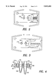
- FIG. 5 is a perspective view, partly exploded, of a modification of the invention.
- FIG. 6 is a side elevational view of the apparatus of FIG. 5;
- FIG. 7 is an opposite side elevational view of the apparatus of FIG. 5.
- FIG. 8 is a sectional view of a portion of the apparatus of FIG. 5.
- FIGS. 1 to 4 show a pulmonary valve 10 for providing oxygen or suction or other treatment to a patient.
- the valve includes two portions 20 and 30 which are coupled together so that they slide with respect to each other to connect different possible treatment sources selectively to a patient.
- the lower portion 20 of valve 10 includes a flat plate 40 which has a top surface 50 and a bottom surface 60, a first bole 70 which is a suction hole, and a second hole 80 which is an oxygen hole, in one mode of operation thereof.
- the oxygen hole 80 communicates with a tube 90 which extends downwardly from the lower surface of the plate 40 and is coupled to a source of oxygen and the suction hole communicates with a tube 100 which extends downwardly from the lower surface of the plate 40 and is coupled to a source of suction.
- the tubes 90 and 100 may be connected to sources of other materials if desired.
- the external tubes may be of different sizes or shaped differently to permit foolproof and easy coupling of other tubing thereto.
- a U-shaped frame portion 100 is secured to the plate 40 to form a housing for the valve 10.
- the upper portion of the valve 30 similarly includes a flat plate 120 to which is secured a U-shaped frame portion 130 which meshes with the lower frame portion 110 to complete the housing for the valve 10.
- the upper flat plate carries two short pipes or tubes 140 and 150 which extend through the plate.
- the pipe 140 is aligned with the hole 70 in plate 40 and the pipe 150 is aligned with the hole 80 in the bottom plate 40.
- the plates 40 and 120 are held together by guide hooks 160 which permit them to slide with respect to each other and a helical spring 170 is disposed between a bumper 180 on the top surface of the upper plate 120 and a guide 190 on the wall of the upper frame member 130 to hold the spring in place.
- the spring normally urges the top plate to the left as seen in FIG. 1.
- a cap 194 is secured to the short tubes or pipes 140 and 150 to couple the two pipes by a single tube to a patient.
- a two-part O-ring or spacer 200 is secured to the top surface of bottom plate 40.
- the O-ring has portions closely surrounding the holes in the plate as shown in FIGS. 1 and 4.
- the ring 200 is of a relatively rigid, rubber-like, flexible material and it is embedded in the top surface of the plate 40.
- the ring is in fluid-tight contact with the surface 50 and prevents leakage of suction or oxygen or other substance along the top surface of the plate 40 from the holes.
- a similar ring or spacer 202 may be positioned along the periphery of the top surface of the plate 40 between the two plates 40 and 120.
- the plates 20 and 120 slide along the O-rings or spacers in liquid tight engagement therewith.
- a source of oxygen is connected to tube 90 and a source of suction is connected to tube 70. These sources are not shown.
- the valve 10 is first expanded by the spring 170 as seen in FIG. 3 and the two plates and associated structure thereof are moved with respect to each other to a first position. In this orientation of the parts, the oxygen source is coupled through tube 150 and the cap 194 to a patient.
- the O-ring 200 prevents any leakage of the oxygen around the holes 70 and 80.
- the operator presses the two parts of the valve together against the spring 170 and the hole 70 carrying suction is fed through tube 140 and the outlet tube in the cap 194 to the patient. Again, the O-ring 200 prevents the suction from leaking around the hole 70.
- FIGS. 5-8 Another pulmonary-use valve 220 embodying the principles of the invention is shown in FIGS. 5-8.
- This valve includes a mouthpiece 224 having a first tubular portion 226 which is placed in a patient's mouth and a second tubular portion 228 extending therefrom which is connected to a source of oxygen (not shown).
- the mouthpiece extends rearwardly through a sliding valve or door mechanism 240 to a third tubular portion 290.
- a cleanout valve 292 is provided in tube 290.
- a cleaning fluid can be introduced through valve 292 to wash out the tube 290 and the end of the catheter held therein.
- a sponge or other cleaning means can be placed in tube 290 as described in U.S. Pat. No. 5,088,486.
- a relatively rigid, thin disk 291 is secured in place, in any suitable fashion, in the open end of tube 290 to effectively seal off this end of tube 290.
- the opposite end of tube 290 is sealed off when desired by apparatus to be described.
- the disk 291 has a slit 293 through which a catheter can be fed into the mouthpiece and into a patient.
- the third tubular portion 290 may be coupled to apparatus of the type shown in Jinotti U.S. Pat. No. 5,140,983.
- the third tube is releasably connected to one end of a collapsible sleeve 244 by means of a locking ring 274 and the other end is releasably connected to an adapter 276 by a locking ring 280.
- the adapter is coupled to the valve 258.
- An arrangement of this type is shown in U.S. Pat. No. 5,346,478 and in U.S. Pat. No. 5,346,478.
- Valve 258 is coupled to sources of oxygen and suction for application to a patient under the control of the valve.
- a dual or single lumen catheter 262 is coupled to the adapter 276 and it is adapted to be inserted through the mouthpiece into a patient by an operator grasping the valve 258 and all of the associated apparatus.
- the sliding door apparatus 240 for controlling the access of the catheter 262.
- the third tube 290 carries disk 291 which has a slit 292 through which the catheter can pass and the passage is controlled by a box-like structure 264 secured between the tube 290 and the tube 224.
- the box has a hole 294 aligned with the opening in the adjacent open end of tube 290.
- a slidable plate 268 is slidably disposed within the box 264 and it has a hole 270 which is adapted, in one position of plate 268, to be aligned with the hole in the box and tube 290 and, in another position it blocks the holes in the box and the tube 290. This latter position is assumed after the catheter is withdrawn from a patient into the tube 290 where it can be cleaned as described in U.S. Pat. No. 5,088,486.
- both ends of the box 264 are provided with notches 295 into which pins 296 and 298 carried at both ends of the slidable plate 268 are adapted to seat in the notches 295 to hold the slidable polate securely in place.
- sealing members 280 like the seal 200 in FIG. 1.
- the sealing members are of a relatively rigid, rubber-like material and they are slightly embedded in the opposed surfaces of the slidable plate 268.
- the sealing members include O-ring portions one of which surrounds the opening in the plate and are in fluid-tight engagemen with the surfaces of the box 264 and prevent leakage from this opening.
- the slidable plate 268 is moved to the position in which the opening 270 therein is aligned with the opening in tube 290 and the catheter assembly is pushed forward to cause the catheter to pass through the mouthpiece into the patient.
- Oxygen and suction are applied as described in the above patents and thereafter the catheter is pulled back through the slidable plate into the tube 290 but in front of the disk 291.
- the slidable plate is moved to the right as seen in FIG. 1 to seat a solid portion of the plate in front of the hole in the end of tube 290 to thereby block the hole and to provide a closed chamber in which the end of the catheter is seated.
- the catheter end may now be washed by means of fluid introduced through valve 292 and the washing fluid may be removed by means of suction applied from valve 258.
- the apparatus of the invention can be disassembled and discarded or some parts may be re-used on the same patient.
- the sleeve 244 encloses the catheter and protects an operator from any material which may be thereon. The assembly of catheter and sleeve can be discarded.
Abstract
Description
Claims (11)
Priority Applications (1)
| Application Number | Priority Date | Filing Date | Title |
|---|---|---|---|
| US08/831,654 US5813402A (en) | 1997-04-09 | 1997-04-09 | Valve for pulmonary catheter |
Applications Claiming Priority (1)
| Application Number | Priority Date | Filing Date | Title |
|---|---|---|---|
| US08/831,654 US5813402A (en) | 1997-04-09 | 1997-04-09 | Valve for pulmonary catheter |
Publications (1)
| Publication Number | Publication Date |
|---|---|
| US5813402A true US5813402A (en) | 1998-09-29 |
Family
ID=25259549
Family Applications (1)
| Application Number | Title | Priority Date | Filing Date |
|---|---|---|---|
| US08/831,654 Expired - Lifetime US5813402A (en) | 1997-04-09 | 1997-04-09 | Valve for pulmonary catheter |
Country Status (1)
| Country | Link |
|---|---|
| US (1) | US5813402A (en) |
Cited By (15)
| Publication number | Priority date | Publication date | Assignee | Title |
|---|---|---|---|---|
| US6189534B1 (en) * | 1998-10-13 | 2001-02-20 | Mallinckrodt Inc. | Bi-functional in-line phonation valve |
| US6227197B1 (en) * | 1997-12-10 | 2001-05-08 | Respironics, Inc. | Gas supplying and substance suctioning relative to a patients trachea |
| US6227200B1 (en) | 1998-09-21 | 2001-05-08 | Ballard Medical Products | Respiratory suction catheter apparatus |
| US6287281B1 (en) * | 1998-07-02 | 2001-09-11 | Scimed Life Systems, Inc. | Low profile retention system |
| WO2002028463A3 (en) * | 2000-10-05 | 2002-06-13 | Kimberly Clark Co | Respiratory care multiple access port assembly and adapter |
| US20030034036A1 (en) * | 1997-09-06 | 2003-02-20 | Franz Waldeck | Tracheotomy cannula with shield plate |
| US6543451B1 (en) | 1999-12-23 | 2003-04-08 | Kimberly-Clark Worldwide, Inc. | Endotracheal catheter and manifold assembly with improved seal and valve |
| US6588427B1 (en) | 2002-02-25 | 2003-07-08 | Kimberly-Clark Worldwide, Inc. | Heat and moisture exchanger adapter to closed suction catheter assembly and system having improved catheter cleaning |
| US6769430B1 (en) | 2000-10-31 | 2004-08-03 | Kimberly-Clark Worldwide, Inc. | Heat and moisture exchanger adaptor for closed suction catheter assembly and system containing the same |
| US7021313B1 (en) | 1998-09-21 | 2006-04-04 | Ballard Medical Products | Respiratory suction catheter apparatus with improved valve and collar |
| US20060102186A1 (en) * | 2004-11-18 | 2006-05-18 | Mark Adler | Intra-bronchial apparatus for aspiration and insufflation of lung regions distal to placement or cross communication and deployment and placement system therefor |
| US7152603B1 (en) | 1999-12-13 | 2006-12-26 | Kimberly-Clark Worldwide, Inc. | Endotracheal catheter and manifold assembly with improved valve |
| US20110001317A1 (en) * | 2009-07-02 | 2011-01-06 | Ti-Li Chang | Changeable Connection Assembly for a Closed Suction Tube |
| EP2275161A1 (en) * | 2009-07-14 | 2011-01-19 | Ti-Li Chang | Changeable connection assembly for a closed suction tube |
| WO2011148120A1 (en) * | 2010-05-26 | 2011-12-01 | Smiths Medical International Limited | Endobronchial tube assemblies and selectors |
Citations (12)
| Publication number | Priority date | Publication date | Assignee | Title |
|---|---|---|---|---|
| US4036210A (en) * | 1975-06-09 | 1977-07-19 | Campbell Roy L | Double lumened catheter |
| US4202330A (en) * | 1978-06-26 | 1980-05-13 | Jariabka Daniel S | Life support system and valve for use therewith |
| US4595005A (en) * | 1984-02-08 | 1986-06-17 | Jinotti Walter J | Dual-purpose catheter |
| US4649914A (en) * | 1985-11-12 | 1987-03-17 | Kowalewski Ryszard J | Rapid self-inflating tracheal tube with constant pressure control feature |
| US4850350A (en) * | 1986-06-23 | 1989-07-25 | Sheridan Catheter Corp. | Closed system combined suction and ventilation devices |
| US4995387A (en) * | 1984-02-08 | 1991-02-26 | Jinotti Walter J | Dual-purpose catheter |
| US5088486A (en) * | 1990-04-11 | 1992-02-18 | Jinotti Walter J | Closed system reusable dual purpose catheter |
| US5191881A (en) * | 1991-01-28 | 1993-03-09 | Genesis Medical, Ltd. | Insufflating/suctioning valve |
| US5255672A (en) * | 1991-08-07 | 1993-10-26 | Jinotti Walter J | Dual-purpose catheter assembly |
| US5487381A (en) * | 1994-04-20 | 1996-01-30 | Jinotti; Walter J. | Closed system for treating pulmonary patient |
| US5511545A (en) * | 1995-01-04 | 1996-04-30 | Jinotti; Walter J. | Valve for pulmonary medical use |
| US5611336A (en) * | 1984-07-23 | 1997-03-18 | Ballard Medical Products, Inc. | Single use medical aspirating device and method |
-
1997
- 1997-04-09 US US08/831,654 patent/US5813402A/en not_active Expired - Lifetime
Patent Citations (12)
| Publication number | Priority date | Publication date | Assignee | Title |
|---|---|---|---|---|
| US4036210A (en) * | 1975-06-09 | 1977-07-19 | Campbell Roy L | Double lumened catheter |
| US4202330A (en) * | 1978-06-26 | 1980-05-13 | Jariabka Daniel S | Life support system and valve for use therewith |
| US4595005A (en) * | 1984-02-08 | 1986-06-17 | Jinotti Walter J | Dual-purpose catheter |
| US4995387A (en) * | 1984-02-08 | 1991-02-26 | Jinotti Walter J | Dual-purpose catheter |
| US5611336A (en) * | 1984-07-23 | 1997-03-18 | Ballard Medical Products, Inc. | Single use medical aspirating device and method |
| US4649914A (en) * | 1985-11-12 | 1987-03-17 | Kowalewski Ryszard J | Rapid self-inflating tracheal tube with constant pressure control feature |
| US4850350A (en) * | 1986-06-23 | 1989-07-25 | Sheridan Catheter Corp. | Closed system combined suction and ventilation devices |
| US5088486A (en) * | 1990-04-11 | 1992-02-18 | Jinotti Walter J | Closed system reusable dual purpose catheter |
| US5191881A (en) * | 1991-01-28 | 1993-03-09 | Genesis Medical, Ltd. | Insufflating/suctioning valve |
| US5255672A (en) * | 1991-08-07 | 1993-10-26 | Jinotti Walter J | Dual-purpose catheter assembly |
| US5487381A (en) * | 1994-04-20 | 1996-01-30 | Jinotti; Walter J. | Closed system for treating pulmonary patient |
| US5511545A (en) * | 1995-01-04 | 1996-04-30 | Jinotti; Walter J. | Valve for pulmonary medical use |
Cited By (24)
| Publication number | Priority date | Publication date | Assignee | Title |
|---|---|---|---|---|
| US20030034036A1 (en) * | 1997-09-06 | 2003-02-20 | Franz Waldeck | Tracheotomy cannula with shield plate |
| US7699055B2 (en) * | 1997-09-06 | 2010-04-20 | Tracoe Gesellschaft Fur Medizinische Bedarfsgegenstande Mbh | Tracheotomy cannula with shield plate |
| US6227197B1 (en) * | 1997-12-10 | 2001-05-08 | Respironics, Inc. | Gas supplying and substance suctioning relative to a patients trachea |
| US20090093770A1 (en) * | 1998-07-02 | 2009-04-09 | Srinivas Nishtala | Low profile retention system |
| US7854725B2 (en) | 1998-07-02 | 2010-12-21 | Boston Scientific Scimed, Inc. | Low profile retention system |
| US6287281B1 (en) * | 1998-07-02 | 2001-09-11 | Scimed Life Systems, Inc. | Low profile retention system |
| US20040111062A1 (en) * | 1998-07-02 | 2004-06-10 | Srinivas Nishtala | Low profile retention system |
| US7481796B2 (en) | 1998-07-02 | 2009-01-27 | Boston Scientific Scimed, Inc. | Low profile retention system |
| US6227200B1 (en) | 1998-09-21 | 2001-05-08 | Ballard Medical Products | Respiratory suction catheter apparatus |
| US6805125B1 (en) | 1998-09-21 | 2004-10-19 | Ballard Medical Products | Respiratory suction catherer apparatus |
| US7021313B1 (en) | 1998-09-21 | 2006-04-04 | Ballard Medical Products | Respiratory suction catheter apparatus with improved valve and collar |
| US6386200B1 (en) * | 1998-10-13 | 2002-05-14 | Mallinckrodt Inc. | Bi-functional in-line phonation valve |
| US6189534B1 (en) * | 1998-10-13 | 2001-02-20 | Mallinckrodt Inc. | Bi-functional in-line phonation valve |
| US7152603B1 (en) | 1999-12-13 | 2006-12-26 | Kimberly-Clark Worldwide, Inc. | Endotracheal catheter and manifold assembly with improved valve |
| US6543451B1 (en) | 1999-12-23 | 2003-04-08 | Kimberly-Clark Worldwide, Inc. | Endotracheal catheter and manifold assembly with improved seal and valve |
| US6612304B1 (en) | 2000-10-05 | 2003-09-02 | Kimberly-Clark Worldwide, Inc. | Respiratory care multiple access port assembly and adapter |
| WO2002028463A3 (en) * | 2000-10-05 | 2002-06-13 | Kimberly Clark Co | Respiratory care multiple access port assembly and adapter |
| US6769430B1 (en) | 2000-10-31 | 2004-08-03 | Kimberly-Clark Worldwide, Inc. | Heat and moisture exchanger adaptor for closed suction catheter assembly and system containing the same |
| US6588427B1 (en) | 2002-02-25 | 2003-07-08 | Kimberly-Clark Worldwide, Inc. | Heat and moisture exchanger adapter to closed suction catheter assembly and system having improved catheter cleaning |
| US7451765B2 (en) * | 2004-11-18 | 2008-11-18 | Mark Adler | Intra-bronchial apparatus for aspiration and insufflation of lung regions distal to placement or cross communication and deployment and placement system therefor |
| US20060102186A1 (en) * | 2004-11-18 | 2006-05-18 | Mark Adler | Intra-bronchial apparatus for aspiration and insufflation of lung regions distal to placement or cross communication and deployment and placement system therefor |
| US20110001317A1 (en) * | 2009-07-02 | 2011-01-06 | Ti-Li Chang | Changeable Connection Assembly for a Closed Suction Tube |
| EP2275161A1 (en) * | 2009-07-14 | 2011-01-19 | Ti-Li Chang | Changeable connection assembly for a closed suction tube |
| WO2011148120A1 (en) * | 2010-05-26 | 2011-12-01 | Smiths Medical International Limited | Endobronchial tube assemblies and selectors |
Similar Documents
| Publication | Publication Date | Title |
|---|---|---|
| US5813402A (en) | Valve for pulmonary catheter | |
| US5247966A (en) | Suction irrigator valve apparatus | |
| US6918902B2 (en) | Irrigation and suction valve and method therefor | |
| JP2009504302A (en) | Endoscope fluid supply device | |
| US5027791A (en) | Air and water supply apparatus for endoscope | |
| EP0123817B1 (en) | Air and liquid supplying device for endoscopes | |
| US4957483A (en) | Sterilizable syringe | |
| US4391280A (en) | Enema apparata improvements relating to double contrast studies | |
| JPH08238312A (en) | Pipe set and irrigation device | |
| US4457487A (en) | Flushing device | |
| US5045055A (en) | Flow control valve assembly for syringes | |
| CN100413548C (en) | Distribution device for a supply network for supply of medical fluids to a patient | |
| US6240960B1 (en) | Back flush valve for one-way flush of drainage catheters | |
| JPH0135234B2 (en) | ||
| JP2967041B2 (en) | Suction irrigation device | |
| JP4132454B2 (en) | Arterial needle hub | |
| EP0071058B1 (en) | Washing device of endoscope fluid pipes | |
| US5941703A (en) | Unidirectional valve for preventing back flow in a dental saliva ejector | |
| US4419099A (en) | Enema apparata improvements relating to double contrast studies | |
| US4333460A (en) | Enema apparata improvements relating double contrast studies | |
| US4386607A (en) | Enema apparata improvements relating to double contrast studies | |
| JP4554808B2 (en) | Endoscope water supply device | |
| JP4192484B2 (en) | Covered endoscope | |
| JP2001061773A (en) | Valve device for endoscope and water feed tube with valve as well as endoscope system | |
| KR20220110780A (en) | Medical devices and related methods of use for agent delivery |
Legal Events
| Date | Code | Title | Description |
|---|---|---|---|
| STCF | Information on status: patent grant |
Free format text: PATENTED CASE |
|
| AS | Assignment |
Owner name: BALLARD MEDICAL PRODUCTS, A UTAH CORPORATION, UTAH Free format text: ASSIGNMENT OF ASSIGNORS INTEREST;ASSIGNOR:JINOTTI, WALTER J.;REEL/FRAME:010144/0779 Effective date: 19990615 |
|
| FEPP | Fee payment procedure |
Free format text: PAT HOLDER NO LONGER CLAIMS SMALL ENTITY STATUS, ENTITY STATUS SET TO UNDISCOUNTED (ORIGINAL EVENT CODE: STOL); ENTITY STATUS OF PATENT OWNER: LARGE ENTITY |
|
| REFU | Refund |
Free format text: REFUND - PAYMENT OF MAINTENANCE FEE, 4TH YR, SMALL ENTITY (ORIGINAL EVENT CODE: R283); ENTITY STATUS OF PATENT OWNER: LARGE ENTITY |
|
| FPAY | Fee payment |
Year of fee payment: 4 |
|
| FEPP | Fee payment procedure |
Free format text: ENTITY STATUS SET TO UNDISCOUNTED (ORIGINAL EVENT CODE: BIG.); ENTITY STATUS OF PATENT OWNER: LARGE ENTITY |
|
| FPAY | Fee payment |
Year of fee payment: 8 |
|
| AS | Assignment |
Owner name: KIMBERLY-CLARK WORLDWIDE, INC., WISCONSIN Free format text: ASSIGNMENT OF ASSIGNORS INTEREST;ASSIGNOR:BALLARD MEDICAL PRODUCTS, INC.;REEL/FRAME:019805/0150 Effective date: 20070910 |
|
| FPAY | Fee payment |
Year of fee payment: 12 |
|
| AS | Assignment |
Owner name: AVENT, INC., GEORGIA Free format text: ASSIGNMENT OF ASSIGNORS INTEREST;ASSIGNOR:KIMBERLY-CLARK WORLDWIDE, INC.;REEL/FRAME:034756/0001 Effective date: 20141030 |
|
| AS | Assignment |
Owner name: MORGAN STANLEY SENIOR FUNDING, INC., NEW YORK Free format text: SECURITY INTEREST;ASSIGNOR:AVENT, INC.;REEL/FRAME:035375/0867 Effective date: 20150227 |
|
| AS | Assignment |
Owner name: CITIBANK, N.A., NEW YORK Free format text: INTELLECTUAL PROPERTY SECURITY INTEREST ASSIGNMENT AGREEMENT;ASSIGNOR:MORGAN STANLEY SENIOR FUNDING, INC.;REEL/FRAME:048173/0137 Effective date: 20181029 |
|
| AS | Assignment |
Owner name: AVANOS MEDICAL SALES, LLC, GEORGIA Free format text: RELEASE BY SECURED PARTY;ASSIGNOR:CITIBANK, N.A.;REEL/FRAME:060557/0062 Effective date: 20220624 Owner name: AVENT, INC., GEORGIA Free format text: RELEASE BY SECURED PARTY;ASSIGNOR:CITIBANK, N.A.;REEL/FRAME:060557/0062 Effective date: 20220624 |