US5812202A - Method and apparatus performing inverse telecine for MPEG coding - Google Patents
Method and apparatus performing inverse telecine for MPEG coding Download PDFInfo
- Publication number
- US5812202A US5812202A US08/410,181 US41018195A US5812202A US 5812202 A US5812202 A US 5812202A US 41018195 A US41018195 A US 41018195A US 5812202 A US5812202 A US 5812202A
- Authority
- US
- United States
- Prior art keywords
- field
- detected
- deletion
- video
- redundant
- Prior art date
- Legal status (The legal status is an assumption and is not a legal conclusion. Google has not performed a legal analysis and makes no representation as to the accuracy of the status listed.)
- Expired - Fee Related
Links
Images


Classifications
-
- H—ELECTRICITY
- H04—ELECTRIC COMMUNICATION TECHNIQUE
- H04N—PICTORIAL COMMUNICATION, e.g. TELEVISION
- H04N7/00—Television systems
- H04N7/01—Conversion of standards, e.g. involving analogue television standards or digital television standards processed at pixel level
- H04N7/0112—Conversion of standards, e.g. involving analogue television standards or digital television standards processed at pixel level one of the standards corresponding to a cinematograph film standard
Definitions
- the present invention relates to video signal processing; and, in particular the present invention relates to encoding motion pictures in a compressed format, such as the format promulgated by the Motion Picture Expert Group (MPEG).
- MPEG Motion Picture Expert Group
- each frame of a video sequence is also divided into first and second fields, which are displayed successively.
- the first field is formed by the odd number scan lines of the video frame and the second field is formed by the even number scan lines of the video frame.
- FIG. 1 illustrates conceptually the telecine process for converting between a motion picture format and a video format.
- FIG. 1 shows four frames of a motion picture, labelled generally by reference signals A, B, C, and D. Each frame is digitized and separated into first and second fields, as indicated generally by reference signals A1, A2, B1, B2, Cl, C2, D1 and D2. Because motion pictures are shown at 24 frames per second and a video sequence is shown at 30 frames or 60 fields a second, two fields are repeated in the video sequence for every four frames, so as to compensate for the higher picture rate in a video sequence. As shown in FIG. 1, fields B1 and D2 are repeated. FIG. 1 also shows the sequence in which the fields are to be displayed: A1, A2, B1, B2, B1, C2, C1, D2, D1 and D2. This pattern (the "telecine pattern”) is repeated for every four frames of the motion picture.
- This pattern (the "telecine pattern") is repeated for every four frames of the motion picture.
- this pattern is referred to by its five phases (i.e. the five frames formed by the eight original fields from the four frames of the motion picture plus the two redundant fields), labelled in FIG. 1 as phases 0, 1, 2, 3 and 4 respectively, each phase involving two fields.
- the Motion Picture Experts Group promulgates a compressed video format (the "MPEG" format) for storing video sequences in digital storage media.
- the MPEG format minimizes the storage requirement for video sequences using data compression techniques which eliminate both interframe and intraframe redundancies. Since redundancy, namely the repeated fields, is introduced in the telecine process, it is desirable to eliminate this redundancy prior to performing data compression.
- a starting point e.g. phase 0
- reversing the telecine process can be accomplished by removing fields B1 and C2 from phase 2. This method, even though it discards information in one field (i.e. field C2), is acceptable in certain applications.
- lossless reconstruction can be achieved by eliminating field B1 from phase 2 and field D2 from phase 3, and reordering fields C1 and C2 in phases 2 and 3, respectively.
- Digital computers are often used to edit video sequences.
- the edited video sequences are often edited without regard to maintaining the telecine pattern.
- Performing a reverse telecine process on such a video sequence results in unacceptable artifacts, especially in a video sequence capturing much motion. As a result, it can be a daunting task to reverse the telecine process in such an edited video sequence.
- the present invention provides a method for automatically identifying redundant fields in a video sequence containing telecined film material.
- the present invention allows such fields to be eliminated (“inverse telecine") prior to data compression, so as to achieve a higher compression efficiency, and to avoid temporal artifacts due to the redundant fields.
- the present invention preserves video-audio synchronization to minimize artifact due to the inverse telecine process, especially in edited material.
- an apparatus for performing an inverse telecine process on a video sequence includes: (a) a phase detector, which provides two control signals indicating, respectively, (i) that a telecine pattern is detected in the video sequence, and (ii) a phase value of a redundant field relative to a preselected position of a repeated sequence in the telecine pattern.
- the states of the two control signals are periodically sampled and stored in registers to be examined periodically by a central processing unit.
- the central processing unit is regularly interrupted to (i) examine the sampled values of the control signals, (ii) determine if a disruption in the telecine pattern of the video sequence has occurred, (iii) determine whether a shift in phase value has occurred; (iv) determine a new phase value at the point of disruption; and (v) include the video field in a encoder control list.
- the central processing unit further groups the video sequence into groups of consecutive fields, each group including a predetermined number of fields.
- the central processing unit marks in each of the groups, a predetermined number of fields for deletion.
- each group includes five frames; and, among the five frames, one frame (i.e. two fields) is marked from deletion.
- the frame marked for deletion is selected in that embodiment according to the rules:
- a control circuit removes from the encoding process the select video fields of the video sequence marked for deletion.
- An encoder receiving the video sequence after such video fields are removed from the encoding process, performs a data compression procedure on the reduced video sequence.
- One implementation prevents the encoder from reading the deleted fields of the video sequence by masking out the synchronization signal indicating the arrivals of the deleted frames.
- FIG. 1 illustrates conceptually the telecine process for converting between a motion picture format and a video format.
- FIG. 2 is a block diagram of system 100, which is an embodiment of the present invention.
- FIG. 3 illustrates using signals FM and F5 of phase detector 201 in a phase detection step of a method in accordance with the present invention.
- FIG. 4 is a flow diagram illustrating a method of the present invention.
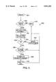
- FIG. 5 summarizes an implementation of a phase detection step in a routine DoPhaseDetect( ), according to the present invention.
- FIG. 6 summarizes an implementation of a normalization step in a routine NormalizePhaseChange( ), according to the present invention.
- Appendix A is a listing including routines DoPhaseDetect() and NormalizePhaseChange(), which are implementations of the phase detection step 500 of FIG. 5 and the normalization step 600 of FIG. 6, respectively.
- the present invention provides a method and an apparatus for performing a reverse telecine process on a video sequence prior to data compression.
- data compression can be performed in accordance with an industry standard, such as MPEG.
- FIG. 2 is a block diagram of system 200, which is an embodiment of the present invention.
- system 200 is based on an environment of a Macintosh computer, available from Apple Computer, Inc., Cupertino, Calif.
- System 200 includes a central processing unit (CPU) 225, which communicates with a memory system 226 over a CPU bus 222.
- CPU bus 222 On CPU bus 222 are serial interface 204 and NuBus interface 205.
- NuBus interface 205 couples CPU bus 222 to an industry standard peripheral bus NuBus 221.
- a video system is coupled to NuBus 221.
- This video system includes a digitizer unit (digitizer 208), a video encoder unit (video encoder 207) and an interface (interface 206) to a phase detector unit (phase detector 201).
- Video encoder 207 which is coupled to digitizer 208 over a dedicated video bus 224, has the ability to interrupt CPU 225 by asserting an interrupt request on NuBus 221.
- Digitizer unit 208 can be implemented, for example, by the Explorer module which is available from Intelligent Resources, Inc., Arlington, Ill., Digitizer unit 208 receives an analog video signal from a video source, such as video tape recorder 203, to provide a digitized video data stream in the luminance-chrominance (YUV) format.
- a video source such as video tape recorder 203
- Encoder 207 can be implemented by an encoder such as that described in the patent application 08/197,914 entitled “System and Method for Digital Video Publishing” by Mauro Bonomi, filed on Feb. 17, 1994, now U.S. Pat. No. 5,577,191 issued on Nov. 19, 1996, assigned to Minerva Corporation, which is also the assignee of the present application.
- interface 206 is coupled to a phase detector (phase detector 201), which receives the video signal from video tape recorder 203, and detects if the fields in the video signal appear in accordance with the telecine pattern discussed above with respect to FIG. 1.
- phase detector 201 phase detector 201
- a video sequence converted from a motion picture follows the telecine pattern throughout the entire sequence, containing very few departures (“disruptions") from the telecine pattern.
- disruption typically occurs between reels of film.
- Disruptions in motion picture material is rare primarily because editing is performed prior to the telecine process.
- "complex materials” such as commercial advertising or music videos, have a much larger number of disruptions per unit of time, as they are typically edited in a video medium, such as a video tape.
- Phase detector 201 provides two control signals FM and F5, which are discussed in further detail below.
- Phase detector 201 can be implemented by the motion sequence pattern detector described in U.S. Pat. No. 4,982,280, entitled “Motion Sequence Pattern Detector for Video” to Lyon et al., filed Jul. 18, 1989 and issued Jan. 1, 1991.
- An implementation of such a phase detector is also available from Faroudja Laboratories, Santa Clara, Calif.
- interface 206 samples the values of signals FM and F5 into interface 206's internal registers periodically, at a frequency much higher than one sixtieth of a second 1 . These internal registers of interface 206 can be polled by CPU 255 over NuBus 221.
- digitizer 208 detects a vertical synchronization signal embedded in the video signal received from video tape recorder 203, as the video signal is digitized. Digitizer 208 also keeps track of whether, in conjunction with the vertical synchronization signal, the first or the second field of a frame is being received. Digitizer 208 passes to encoder 207 both the field and the vertical synchronization signal, which appears at the beginning of each field, i.e.
- encoder 207 interrupts CPU 225. This interrupt from encoder 207 is handled by CPU 225 polling the values of the FM and F5 signals from the aforementioned internal registers of interface 206.
- the present invention is an "inverse telecine" procedure which uses the states of signals FM and F5 to mark for deletion the redundant fields resulted from a telecine step, so as to enhance video compression performance.
- the present invention ensures that the reduced video sequence remain synchronized to the audio portion.
- a method according to the present invention is illustrated in FIG. 4 in flow diagram form.
- a phase detection step 401 receives as input data identification information of video fields in a video sequence, indicated by reference numeral 451, and the states of signals FM and F5 associated each video field, indicated by reference numerals 452.
- identification information 451 includes a time code from which the video information in the field can be identified and from which the information as to whether the field is the first or the second field of a frame can also be derived.
- Phase detection step 401 detects any disruption in the telecine pattern, in the manner described in further detail below, and provides an encoder control list ("ECL"), indicated by reference numeral 454, which identifies, for each disruption, the field at which the disruption occurs and the new phase entered at the disruption.
- ECL encoder control list
- Each entry in an ECL of the present embodiment includes a time code, a directive and a phase number.
- the time code identifies the video frame in the video sequence.
- the directive provides is provided to direct the operation of encoder 207 with respect to the compression operation.
- the directive supported in this embodiment are "PHASE CHANGE", “DROP”, “KEEP”, "START” and "STOP".
- ECL 454 the frame number, rather than the field number, is included in ECL 454.
- the present embodiment allows an optional edit step, indicated by reference numeral 402, in which both ECL 454 and any other ECLs related to the video sequence, indicated by reference numeral 455, can be manually edited and merged to provide an edited ECL 456. Manual editing introduces additional flexibility.
- ECL 456 is then provided to a "normalization" step, indicated by reference numeral 403, which ensures that the inverse telecine process, i.e. marking for deletion frames including redundant fields, maintains synchronization between the video information and the audio information.
- Normalization step 403 achieves synchronization by ensuring that the overall deletion is 20% of the frames, and the deleted frames are substantially uniformly spaced within the video sequence.
- Normalization step 403 provides a revised ECL, indicated by reference numeral 457, which is used in an encoding step, indicated by reference numeral 451, for encoding video data 451 into compressed data (458) under an industry standard compressed format, such as that defined by the MPEG standard.
- FIG. 3 illustrates phase detection step 401 using signals FM and F5 of phase detector 201.
- Signal FM which is represented by waveform 301 of FIG. 3, is asserted when the video sequence received exhibits a telecine pattern, such as that shown in FIG. 1. In this embodiment, signal FM can usually detect the telecine pattern after examining fifteen fields or so.
- Signal F5, which is represented by waveform 302, is asserted by phase detector 201, when signal FM is asserted, at phases 2 and 4 (FIG. 1). Phases 2 and 4 correspond to the frames at which fields B1 and D2 are duplicated, respectively.
- Line 303 of FIG. 3 is marked by a number of tick marks indicating arrivals of video fields. Each video field's arrival is indicated by a vertical synchronization signal. In FIG. 3, phase numbers are provided underneath line 303 to help illustrate the phase detection process.
- phase detector 201 detects the telecine pattern and asserts signal FM.
- phase detector 201 asserts signal F5.
- signal F5 is again asserted.
- the telecine pattern are often disrupted by video editing after the telecine process.
- signal FM is negated until phase detector 201 again detects the telecine pattern, e.g. at time t 5 .
- the phase at the disruption is provided by, assuming that no additional disruptions occurred during the period during which signal FM is negated, retracing the telecine pattern backwards in time back to the time of the disruption. For example, as signal F5 is once again asserted at time t 6 , at the arrival of the first field in a frame, time t 6 therefore marks the arrival of a phase 2 frame. Tracing backwards in time back to time t 4 , assuming no interim disruption, the phase at time t 4 is found to be phase 1 (labelled in FIG. 3 as phase 1'). In this embodiment, on rare occasions, the traced back phase is the same as the phase which would have been if no disruption has occurred. In that situation, no disruption is deemed to have occurred.
- phase detection step 401 is provided in the present embodiment as a routine "DoPhaseDetect()" which is executed by CPU 225 whenever encoder 207 interrupts CPU 255 at each field of the video sequence.
- a listing of routine DoPhaseDetect() is provided as Appendix A.
- FIG. 5 summarizes in flow chart 500 the various steps in routine DophaseDetect(). As shown in FIG. 5, when routine DoPhaseDetect() is invoked (step 501), the identification of the current video field (i.e. the current time code) is examined, at step 502, to determine if video field is within the video sequence in which inverse telecine is to be performed. If the video field is out of range, routine DoPhaseDetect() returns (step 510).
- the current time code is synchronized to the current states of signals FM and FS, in step 503, by associating the current states of signals FM and F5 with their corresponding video fields, giving effect to the latency in phase detector 201. Then, in step 504, the current states of signals FM and F5 are read from the internal registers of interface 206.
- the current state of signal FM is determined. If signal FM is currently negated (i.e. a "video” state) and signal FM, as last examined, is asserted (i.e. a "film” state), a disruption is deemed detected. The start time of the disruption is then noted at step 507 and routine DoPhaseDetect() returns. Otherwise, if both the current and last states are video states, routine DoPhaseDetect() returns. Alternatively, if signal FM is asserted, then the current state of signal F5 is examined in step 506. Since signal F5 is asserted at either phase 2 or phase 4, a negated state of signal F5, while signal FM is asserted, does not provide sufficient information to determine the current phase.
- Routine DoPhaseDetect() returns if the current phase is unknown. However, if the current phase is either 2 or 4, routine DoPhaseDetect() then traces back to the time of disruption, in the manner described above, to compute at step 508 the phase of the video field at the last disruption. At step 509, the time of the disruption and its associated phase are entered into ECL 454 as a phase change. Routine DoPhaseDetect() then returns. Steps 505 and 506 are accomplished, in the present embodiment, by the routine GetActualPhase, which is also listed in Appendix A.
- ECL 454 is provided as ASCII text
- edit step 402 of FIG. 4 can be accomplished by any text editor.
- the goal of normalization step 403 of FIG. 4 is to ensure that the video and the audio portions of the video sequence remain synchronized after the inverse telecine process.
- One way to achieve this goal is to distribute the fields marked for deletion substantially uniformly throughout the video sequence.
- uniformity is achieved by dividing the video sequence into groups of five frames (i.e. 10 fields in each group) and requiring one frame (i.e. two fields) to be marked for deletion in each group.
- the deletion rules in the present embodiment are provided as follows:
- phase 2 frame is marked for deletion by default
- phase 2 frame latest in time is marked for deletion.
- Rule 1 above which marks for deletion the frame at the disruption, when no phase 2 frame is in a group of five frames, minimizes noticeable artifacts when the video sequence is later viewed. This is because the disruption typically occurs at a scene change, sometimes resulting from splicing together two independently created video sequences.
- marking for deletion the frame at the disruption is a design choice.
- An equally valid choice is marking for deletion the frame immediately preceding the disruption.
- Rule 3 which keeps all redundant frames in a group of five frames except the last frame, also exercise a design choice. Clearly, deleting any one of the redundant frames is an equally valid design choice.
- Routine NormalizePhaseChange() is summarized in FIG. 6.
- CPU 225 masks out the vertical synchronization signals for phase 2 frames received at encoder 207, so that phase 2 frames are dropped from encoding in encoder 207.
- This feature limits ECL 457 to a manageable size.
- ECL 457 specifically directing that the phase 2 frame be kept (i.e. an ECL entry with the directive "KEPT").
- routine NormalizePhaseChange() needs only consider the frames located immediately before and after a disruption.
- routine NormalizePhaseChange() first computes, for each disruption, the position (modulo 5) of the disruption, relative to the beginning of the video sequence. This position represents also the position of disruption in a group of five frames.
- the phases of the frames prior to the disruption within the group of five frames are computed using the phase entered at the last disruption.
- the phases at and subsequent to the disruption are determined from ECL 456.
- the number of phase 2 frames within the group of five frames are then tallied at step 604. If there is no phase 2 frame in the group of five frames, the frame at the disruption is marked deleted at step 606, by entering into ECL 457 an entry identifying the frame and marking the directive field of the entry "DROP".
- phase detection techniques other than those disclosed in the Lyon '280 patent discussed above, can be used to provide the information necessary to decode the phase information whenever the telecine pattern is encountered.
- present embodiment discard both fields of a frame marked for deletion, the present invention can also be carried out by examining all the fields in a normalization group and select two fields, whether or not belonging to the same frame to be discarded.
- the present invention is defined by the following claims. ##SPC1##
Abstract
Description
Claims (12)
Priority Applications (1)
| Application Number | Priority Date | Filing Date | Title |
|---|---|---|---|
| US08/410,181 US5812202A (en) | 1995-03-24 | 1995-03-24 | Method and apparatus performing inverse telecine for MPEG coding |
Applications Claiming Priority (1)
| Application Number | Priority Date | Filing Date | Title |
|---|---|---|---|
| US08/410,181 US5812202A (en) | 1995-03-24 | 1995-03-24 | Method and apparatus performing inverse telecine for MPEG coding |
Publications (1)
| Publication Number | Publication Date |
|---|---|
| US5812202A true US5812202A (en) | 1998-09-22 |
Family
ID=23623589
Family Applications (1)
| Application Number | Title | Priority Date | Filing Date |
|---|---|---|---|
| US08/410,181 Expired - Fee Related US5812202A (en) | 1995-03-24 | 1995-03-24 | Method and apparatus performing inverse telecine for MPEG coding |
Country Status (1)
| Country | Link |
|---|---|
| US (1) | US5812202A (en) |
Cited By (12)
| Publication number | Priority date | Publication date | Assignee | Title |
|---|---|---|---|---|
| WO2001063426A1 (en) * | 2000-02-23 | 2001-08-30 | Teranex, Inc. | Distribution, processing, and reconstruction of variable-sized images using multiple processor arrays |
| GB2361134A (en) * | 2000-04-07 | 2001-10-10 | Snell & Wilcox Ltd | Video standards conversion |
| US6441813B1 (en) * | 1997-05-16 | 2002-08-27 | Kabushiki Kaisha Toshiba | Computer system, and video decoder used in the system |
| US6525774B1 (en) * | 1999-01-27 | 2003-02-25 | Pioneer Corporation | Inverse telecine converting device and inverse telecine converting method |
| US6724433B1 (en) * | 2000-12-06 | 2004-04-20 | Realnetworks, Inc. | Automated inverse telecine conversion |
| US20040090554A1 (en) * | 2002-10-23 | 2004-05-13 | Takahiro Nishi | Picture coding method |
| US20040136687A1 (en) * | 2003-01-02 | 2004-07-15 | Mediatek Inc. | Signal processing method to selectively record image signals |
| US20040135924A1 (en) * | 2003-01-10 | 2004-07-15 | Conklin Gregory J. | Automatic deinterlacing and inverse telecine |
| WO2005032114A2 (en) * | 2003-09-25 | 2005-04-07 | Wis Technologies, Inc. | System and method for efficiently performing an inverse telecine procedure |
| US20070104273A1 (en) * | 2005-11-10 | 2007-05-10 | Lsi Logic Corporation | Method for robust inverse telecine |
| US20110157304A1 (en) * | 2009-07-01 | 2011-06-30 | Sam Savoca | Three-dimensional television and motion picture method and apparatus |
| US11349962B2 (en) * | 2017-07-03 | 2022-05-31 | Xi'an Zhongxing New Software Co., Ltd. | Data transmission method and device |
Citations (4)
| Publication number | Priority date | Publication date | Assignee | Title |
|---|---|---|---|---|
| US4876596A (en) * | 1988-10-25 | 1989-10-24 | Faroudja Y C | Film-to-video converter with scan line doubling |
| US4967271A (en) * | 1989-04-05 | 1990-10-30 | Ives C. Faroudja | Television scan line doubler including temporal median filter |
| US5353119A (en) * | 1990-11-15 | 1994-10-04 | Sony United Kingdom Limited | Format conversion of digital video signals, integration of digital video signals into photographic film material and the like, associated signal processing, and motion compensated interpolation of images |
| US5452011A (en) * | 1994-03-14 | 1995-09-19 | Thomson Consumer Electronics, Inc. | Method and device for film-mode detection and field elimination |
-
1995
- 1995-03-24 US US08/410,181 patent/US5812202A/en not_active Expired - Fee Related
Patent Citations (4)
| Publication number | Priority date | Publication date | Assignee | Title |
|---|---|---|---|---|
| US4876596A (en) * | 1988-10-25 | 1989-10-24 | Faroudja Y C | Film-to-video converter with scan line doubling |
| US4967271A (en) * | 1989-04-05 | 1990-10-30 | Ives C. Faroudja | Television scan line doubler including temporal median filter |
| US5353119A (en) * | 1990-11-15 | 1994-10-04 | Sony United Kingdom Limited | Format conversion of digital video signals, integration of digital video signals into photographic film material and the like, associated signal processing, and motion compensated interpolation of images |
| US5452011A (en) * | 1994-03-14 | 1995-09-19 | Thomson Consumer Electronics, Inc. | Method and device for film-mode detection and field elimination |
Cited By (24)
| Publication number | Priority date | Publication date | Assignee | Title |
|---|---|---|---|---|
| US6441813B1 (en) * | 1997-05-16 | 2002-08-27 | Kabushiki Kaisha Toshiba | Computer system, and video decoder used in the system |
| US6525774B1 (en) * | 1999-01-27 | 2003-02-25 | Pioneer Corporation | Inverse telecine converting device and inverse telecine converting method |
| US6425026B1 (en) | 2000-02-23 | 2002-07-23 | Teranex, Inc. | Distribution, processing, and reconstruction of variable-sized images using multiple processor arrays |
| WO2001063426A1 (en) * | 2000-02-23 | 2001-08-30 | Teranex, Inc. | Distribution, processing, and reconstruction of variable-sized images using multiple processor arrays |
| GB2361134A (en) * | 2000-04-07 | 2001-10-10 | Snell & Wilcox Ltd | Video standards conversion |
| US7369179B1 (en) * | 2000-12-06 | 2008-05-06 | Realnetworks, Inc. | Automated inverse telecine conversion |
| US6724433B1 (en) * | 2000-12-06 | 2004-04-20 | Realnetworks, Inc. | Automated inverse telecine conversion |
| US7898599B2 (en) | 2000-12-06 | 2011-03-01 | Realnetworks, Inc. | Automated inverse telecine conversion |
| US20080211965A1 (en) * | 2000-12-06 | 2008-09-04 | Realnetworks, Inc. | Automated inverse telecine conversion |
| US20040090554A1 (en) * | 2002-10-23 | 2004-05-13 | Takahiro Nishi | Picture coding method |
| US20040136687A1 (en) * | 2003-01-02 | 2004-07-15 | Mediatek Inc. | Signal processing method to selectively record image signals |
| US7605866B2 (en) | 2003-01-10 | 2009-10-20 | Realnetworks, Inc. | Automatic deinterlacing and inverse telecine |
| US7154555B2 (en) | 2003-01-10 | 2006-12-26 | Realnetworks, Inc. | Automatic deinterlacing and inverse telecine |
| US20070024703A1 (en) * | 2003-01-10 | 2007-02-01 | Conklin Gregory J | Automatic deinterlacing and inverse telecine |
| US20100225805A1 (en) * | 2003-01-10 | 2010-09-09 | Realnetworks, Inc. | Video processor and method for automated deinterlacing and inverse telecine |
| US20040135924A1 (en) * | 2003-01-10 | 2004-07-15 | Conklin Gregory J. | Automatic deinterlacing and inverse telecine |
| US7136414B2 (en) * | 2003-09-25 | 2006-11-14 | Micronas Usa, Inc. | System and method for efficiently performing an inverse telecine procedure |
| WO2005032114A3 (en) * | 2003-09-25 | 2006-08-31 | Wis Technologies Inc | System and method for efficiently performing an inverse telecine procedure |
| US20050078176A1 (en) * | 2003-09-25 | 2005-04-14 | Wis Technologies, Inc. | System and method for efficiently performing an inverse telecine procedure |
| WO2005032114A2 (en) * | 2003-09-25 | 2005-04-07 | Wis Technologies, Inc. | System and method for efficiently performing an inverse telecine procedure |
| US20070104273A1 (en) * | 2005-11-10 | 2007-05-10 | Lsi Logic Corporation | Method for robust inverse telecine |
| US8401070B2 (en) * | 2005-11-10 | 2013-03-19 | Lsi Corporation | Method for robust inverse telecine |
| US20110157304A1 (en) * | 2009-07-01 | 2011-06-30 | Sam Savoca | Three-dimensional television and motion picture method and apparatus |
| US11349962B2 (en) * | 2017-07-03 | 2022-05-31 | Xi'an Zhongxing New Software Co., Ltd. | Data transmission method and device |
Similar Documents
| Publication | Publication Date | Title |
|---|---|---|
| US5812202A (en) | Method and apparatus performing inverse telecine for MPEG coding | |
| EP0961495B1 (en) | Image data processing | |
| JPH04207878A (en) | Moving image management device | |
| US6389171B1 (en) | Method and apparatus for a digital video cassette (DVC) decode system | |
| EP0520444A2 (en) | Method and apparatus for recording compressed audio data on a video record medium | |
| US5963702A (en) | Device and method for recording broadcast signal | |
| US6031959A (en) | Television signal recording and reproducing apparatus | |
| US5392129A (en) | Digital VCR signal processing apparatus for concealing uncorrectable errors | |
| US5434673A (en) | Digital information transferring apparatus capable of identifying the type of device supplied with the transferred information | |
| JPH07236153A (en) | Detection of cut point of moving picture and device for detecting cut picture group | |
| US4764820A (en) | Picture element arranging method in video data recording-reproducing system | |
| US20010048805A1 (en) | Method for regenerating the original data of a digitally coded video film, and apparatus for carrying out the method | |
| US7440503B2 (en) | Decoding apparatus and decoding method in an order opposite to the encoding order | |
| US20030026487A1 (en) | Image decoding apparatus, recording medium which computer can read from, and program which computer can read | |
| JP3067043B2 (en) | Automatic video cutting method | |
| JP3158603B2 (en) | Digital image signal transmission equipment | |
| MY116102A (en) | Digital video recording apparatus and method | |
| US6038370A (en) | Recording and/or reproducing device and its method | |
| US5455683A (en) | Method for preventing error speading while recording compressed image data | |
| US6721116B1 (en) | Method for determining whether tape is recordable and apparatus therefor | |
| JP3353317B2 (en) | Digital image signal recording device | |
| WO1997026760A1 (en) | Picture encoding, recording, and reproducing device | |
| JP2994047B2 (en) | Information recording / reproducing device | |
| JP3534600B2 (en) | Digital signal recording / playback device | |
| JPH05114251A (en) | Error correcting method |
Legal Events
| Date | Code | Title | Description |
|---|---|---|---|
| AS | Assignment |
Owner name: MINERVA SYSTEMS, INC., CALIFORNIA Free format text: ASSIGNMENT OF ASSIGNORS INTEREST;ASSIGNORS:NG, JOHNNY C.Y.;EVANS, KEITH M.;BONOMI, MAURO;REEL/FRAME:007423/0507 Effective date: 19950324 |
|
| AS | Assignment |
Owner name: SILICON VALLEY BANK, CALIFORNIA Free format text: SECURITY AGREEMENT;ASSIGNOR:MINERVA SYSTEMS, INC.;REEL/FRAME:009980/0811 Effective date: 19990414 |
|
| AS | Assignment |
Owner name: SILICON VALLEY BANK, CALIFORNIA Free format text: SECURITY AGREEMENT;ASSIGNOR:MINERVA NETWORKS, INC.;REEL/FRAME:011052/0409 Effective date: 20000616 |
|
| FPAY | Fee payment |
Year of fee payment: 4 |
|
| AS | Assignment |
Owner name: PRESIDIO MANAGEMENT GROUP IV, LP, CALIFORNIA Free format text: SECURITY INTEREST;ASSIGNOR:MINERVA NETWORKS, INC.;REEL/FRAME:015302/0921 Effective date: 20040505 |
|
| AS | Assignment |
Owner name: MINERVA NETWORKS, INC., CALIFORNIA Free format text: TERMINATION AND RELEASE OF SECURITY INTEREST;ASSIGNOR:PRESIDIO MANAGEMENT GROUP IV, L.P., AS COLLATERAL AGENT;REEL/FRAME:015766/0580 Effective date: 20050311 |
|
| REMI | Maintenance fee reminder mailed | ||
| LAPS | Lapse for failure to pay maintenance fees | ||
| STCH | Information on status: patent discontinuation |
Free format text: PATENT EXPIRED DUE TO NONPAYMENT OF MAINTENANCE FEES UNDER 37 CFR 1.362 |
|
| FP | Lapsed due to failure to pay maintenance fee |
Effective date: 20060922 |