US5811792A - Method and apparatus for accessing contents of envelopes and other similarly concealed information - Google Patents
Method and apparatus for accessing contents of envelopes and other similarly concealed information Download PDFInfo
- Publication number
- US5811792A US5811792A US08/778,077 US77807797A US5811792A US 5811792 A US5811792 A US 5811792A US 77807797 A US77807797 A US 77807797A US 5811792 A US5811792 A US 5811792A
- Authority
- US
- United States
- Prior art keywords
- envelopes
- information
- thermal
- radiation
- pattern
- Prior art date
- Legal status (The legal status is an assumption and is not a legal conclusion. Google has not performed a legal analysis and makes no representation as to the accuracy of the status listed.)
- Expired - Fee Related
Links
Images


Classifications
-
- B—PERFORMING OPERATIONS; TRANSPORTING
- B07—SEPARATING SOLIDS FROM SOLIDS; SORTING
- B07C—POSTAL SORTING; SORTING INDIVIDUAL ARTICLES, OR BULK MATERIAL FIT TO BE SORTED PIECE-MEAL, e.g. BY PICKING
- B07C3/00—Sorting according to destination
- B07C3/10—Apparatus characterised by the means used for detection ofthe destination
- B07C3/14—Apparatus characterised by the means used for detection ofthe destination using light-responsive detecting means
-
- B—PERFORMING OPERATIONS; TRANSPORTING
- B07—SEPARATING SOLIDS FROM SOLIDS; SORTING
- B07C—POSTAL SORTING; SORTING INDIVIDUAL ARTICLES, OR BULK MATERIAL FIT TO BE SORTED PIECE-MEAL, e.g. BY PICKING
- B07C1/00—Measures preceding sorting according to destination
-
- Y—GENERAL TAGGING OF NEW TECHNOLOGICAL DEVELOPMENTS; GENERAL TAGGING OF CROSS-SECTIONAL TECHNOLOGIES SPANNING OVER SEVERAL SECTIONS OF THE IPC; TECHNICAL SUBJECTS COVERED BY FORMER USPC CROSS-REFERENCE ART COLLECTIONS [XRACs] AND DIGESTS
- Y10—TECHNICAL SUBJECTS COVERED BY FORMER USPC
- Y10S—TECHNICAL SUBJECTS COVERED BY FORMER USPC CROSS-REFERENCE ART COLLECTIONS [XRACs] AND DIGESTS
- Y10S209/00—Classifying, separating, and assorting solids
- Y10S209/90—Sorting flat-type mail
Definitions
- the invention relates to the acquisition of encoded information from the contents of sealed envelopes or other layered structures that conceal the information from view.
- Much of bulk return mail is processed with at least some manual handling, especially when it contains orders.
- the envelopes Once cut open, the envelopes are generally emptied by hand, and information from their contents is keyboarded, optically scanned, or otherwise entered into a computer.
- the required steps of opening the envelopes, separating their contents, and entering relevant data are expensive and time consuming. Also, data entry is subject to error, especially when information from the separated envelopes must be linked to information from their contents.
- Outgoing mail which may be passed through inserters, is also subject to sorting and other processing errors that are difficult to detect; because once sealed, the contents are concealed from view.
- Various attempts have been made to "see through” the envelopes to read their contents without opening them, but problems plague each.
- U.S. Pat. No. 5,522,921 to Custer proposes use of x-rays for reading envelope contents that are printed with special x-ray opaque materials.
- the x-rays are intended to penetrate the envelopes and their contents except where blocked by the special materials.
- a resulting shadow pattern is detected by an x-ray reading device.
- the special materials add expense and limit printing options, and the x-rays pose health risks that are difficult to justify for these purposes.
- U.S. Pat. No. 5,288,994 to Berson uses infrared light in a similar manner to read the contents of sealed envelopes.
- a light source directs a beam of the infrared light through the envelopes to an optical detector that records a shadow pattern caused by different absorption characteristics between conventional inks and the paper on which they are printed.
- Such filled envelopes make poor optical elements for transmitting images, even for transmissions in the infrared spectrum. Paper does not transmit the infrared images very efficiently. Irregularities in the surfaces, spacing, layering, and materials of the envelopes and their contents cause significant aberrations that can greatly diminish resolution of the images. Also, overlays of printed material on the envelopes and their contents are difficult to separate, and printed backgrounds can reduce contrast.
- Our invention takes a different approach to accessing information from the contents of sealed envelopes or other layered structures by separating the optical functions of illuminating and imaging the concealed information. For example, none of the radiation involved with illuminating the information is also involved with its imaging. Instead, a non-optical mechanism transfers a reproduction of the illuminated information to an exterior surface, where it can be directly imaged or otherwise freely accessed.
- a selected wavelength of light longer than infrared radiation is used to penetrate the envelopes.
- Microwaves or radio waves can be used--either of which transmit through paper or similar materials much better than infrared radiation.
- An information pattern recorded in the contents of the envelopes is arranged to have a different absorption coefficient to the selected wavelength than the remaining contents. Radiant energy differentially absorbed by the information pattern is first converted into a corresponding thermal pattern and is then conducted to respective outer surfaces of the envelopes by transfers of kinetic energy. Once exposed on the envelopes' outer surfaces, the thermal pattern is imaged onto an infrared camera or otherwise detected by temperature-sensitive instruments.
- the radiant energy can be absorbed within the information pattern by induction heating or dielectric heating depending on the materials used to encode the information.
- the oscillating electromagnetic fields of the selected wavelength radiation can induce eddy currents in specially matched conductive materials or mechanical vibrations in specially matched dielectric materials for differentially heating the information pattern.
- the absorption characteristics of such materials that can be used as inks or ink additives are well known or can be readily determined.
- carbon-based inks work well for induction heating
- materials (such as micro-encapsulated water) having polar molecules with high dielectric constants work well for dielectric heating.
- the radiation that penetrates the envelopes is used to differentially heat the information patterns rather than to project images of the patterns through the envelopes. No images of the information patterns are formed until thermal representations of the information patterns are conducted to the outer surfaces of the envelopes. Then, the thermal representations can be imaged by focusing infrared radiation from the representations on an infrared detector array or can be otherwise captured by detecting temperature differences throughout the pattern.
- Our new approach to acquiring information concealed within envelopes is preferably practiced with an in-line system including separate stages for irradiating the envelopes and detecting the thermal pattern transferred to the outer surfaces of the envelopes.
- a transporter moves a succession of the envelopes having information patterns imprinted in their contents through the separate stations.
- a radiation emitter irradiates the envelopes with radiation having a wavelength longer than infrared light for penetrating the envelopes and for differentially heating the information patterns imprinted in their contents.
- a compactor compresses the envelopes and their contents for enhancing conduction of corresponding thermal patterns of the differentially heated information patterns to outer surfaces of the envelopes.
- a detector converts the thermal patterns on the outer surfaces of the envelopes into corresponding electrically processable patterns for accessing the information recorded in the contents of the envelopes.
- Well-known pattern recognition programs can be used to read the recorded information for controlling subsequent operations. For example, orders and customer-identifying codes from return mail can be read for processing orders. Inside addresses or other contents of outgoing mail can be verified or used as a basis for printing information including address information on the outside of the envelopes.
- FIG. 1 is a diagram of an in-line system having a series of stations for accessing information within sealed envelopes.
- FIG. 2 is a cut-away view of one of the envelopes revealing an information pattern among its contents. A thermal representation of the information pattern is depicted on the envelope's surface.
- FIG. 3 is a diagram of an alternative radiation emitter for exposing the envelopes to radio waves instead of microwaves.
- FIG. 4 is a diagram of a similar radiation emitter with two electrodes that are positioned differently.
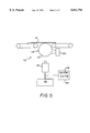
- FIG. 5 is a diagram of an alternative detector for converting the thermal representation of the information pattern into an electronically processable representation.
- FIG. 1 An exemplary in-line system 10 for acquiring information concealed within a succession of sealed envelopes 12 is depicted in FIG. 1.
- the envelopes 12 are preferably opaque to visible light.
- a transporter 14 formed in part by series of endless belts 16 and 18 moves the envelopes 12 through a series of stations, which include a radiation emitter 20, a compactor 22, and a detector 24.
- a magnetron 26 of the radiation emitter 20 emits a predetermined wavelength of microwave radiation into a slotted waveguide 28 that broadcasts the microwaves over an area through which the envelopes 12 are transported. As seen in FIG. 2, the microwaves penetrate the envelopes 12 and differentially heat information patterns 30 that are printed on their contents 32, such as letters or other inserts.
- a load 34 which can be cooled by conventional means, captures excess microwave radiation passing through the envelopes 12.
- the information patterns 30, which are shown in FIG. 2, are formed by printing substances 36 on substrates 38.
- the printing substances 36 have absorption peaks in the vicinity of the predetermined wavelength of microwave radiation, and the substrates 38 (as well as the envelopes 12) do not similarly absorb the predetermined wavelength.
- the absorbed radiation can be converted into heat by either induction heating or dielectric heating depending on the relative characteristics of the printed substances 36 and the substrates 38.
- conductive inks such as carbon black, indium tin oxide, silver graphite, and flexo-carbon ink that is N-propyl acetate based
- conductive inks such as carbon black, indium tin oxide, silver graphite, and flexo-carbon ink that is N-propyl acetate based
- Substances containing polar molecules with a high dielectric constant, such as micro-encapsulated water or titanium dioxide, can be used to convert the selected wavelengths into heat by dielectric heating.
- the substrates 38 are preferably paper, which is a dielectric.
- other non-conducting materials including resin films or fabric materials can also be used as substrates for supporting conductive substances subject to induction heating; and other materials including dielectric materials having different absorption characteristics can be used as substrates for supporting dielectric substances subject to dielectric heating.
- the preferred frequency band for microwave heating is between 300 and 3000 megahertz.
- the compactor 22 which is depicted as a pair of rollers 40, compresses the envelopes 12 and their respective contents 32 together to assist conduction of thermal representations 42 of the differentially heated information patterns 30 to outer surfaces 44 of the envelopes 12.
- the thermal representations 42 are conducted through the envelopes 12 and any intervening layers to the outer surfaces 44 by transfers of kinetic energy. Compressing the envelopes 12 limits the distance and the amount of air through which the representations 42 must be conducted before reaching the outer surfaces 44.
- Coolers 46 remove any excess heat transferred to the rollers 40 to prevent unwanted transfers of heat from the rollers 40 to succeeding envelopes 12.
- a vacuum pump (not shown) could be used in place of the rollers 40 to evacuate air from between the envelopes 12 and their contents 32.
- Compacting can also be accomplished by passing the envelopes 12 through an electrostatic field that generates an attractive force between oppositely charged surfaces of the envelopes.
- the detector 24 which is preferably an infrared camera 52, converts the thermal representations 42 on the outer surfaces 44 into electronically processable representations 48 shown on a video display 50.
- infrared radiation emitted from the thermal representations 42 is focused onto a detector array of the infrared camera 52.
- Signals 54 convey the electronically processable representations 48 of the imaged thermal representations 42 to a computer 56 for further processing.
- Capturing such images of the thermal representations 42 from rapidly moving envelopes 12 may require use of some specialized electronic equipment such as sliding buffers to assemble the images from the changing output of linear detector arrays.
- Such equipment for assembling images of the outer surfaces of moving envelopes is already well known and can be readily adapted for use with infrared detectors.
- conventional recognition programs can be run to interpret the information pattern 30.
- a variety of further processing can take place based on the information acquired from the contents 32 of the envelopes.
- the envelopes 12 can be sorted according to their contents, orders or replies can be generated, records can be updated, or the information can be verified.
- a conventional printer 58 is controlled to print information on the envelopes' outer surfaces 44, which is linked to the information acquired from the contents 32 of the envelopes 12.
- addresses can be printed to match address or other identifying information acquired from the contents 32 of the envelopes 12.
- FIGS. 3 and 4 show two alternative radiation emitters 70 and 90, which can be substituted for the radiation emitter 20 of FIG. 1 to irradiate the envelopes 12 with radio waves instead of microwaves.
- the information patterns 30 shown in FIG. 2 can be differentially heated by either induction heating or dielectric heating, but the absorption peak is within the spectrum of radio waves.
- the preferred frequency band of the radio waves is between 2 megahertz and 300 megahertz.
- the radiation emitter 70 includes a radio frequency generator 72 and two electrodes 74 and 76.
- the envelopes 12 are advanced by an alternative transporter 78 through a fringe portion 80 of an electric field 82 between the two electrodes 72 and 74.
- Endless belts 84 and 86 of the transporter 78 are spaced apart in the vicinity of the electrodes 74 and 76 to preserve the structure of the electric field 82.
- the radiation emitter 90 includes a similar radio frequency generator 92 and two electrodes 94 and 96.
- An alternative transporter 98 advances the envelopes 12 between the two electrodes 94 and 96 for exposing the envelopes to a central portion 100 of an electric field 102.
- endless belts 104 and 106 are spaced apart to avoid disturbing the electric field 102.
- the detector 110 includes a drum 112 coated with a thermosensitive material that reacts to temperature variations by changing in color. Accordingly, the thermal representation 42 on the outer surfaces 44 of the envelopes 12 is converted into a color pattern 114.
- a camera 116 sensitive to light within the visible spectrum converts an image of the color pattern 114 into an electronically representation 118 that can be further processed by the computer 56.
- a cooler 120 resets the drum to a constant temperature for recording another thermal representation 42.
- detectors could also be used for recording thermal representations 42 including detectors for directly sensing temperature variations on the envelopes' outer surfaces. Coolers could also be used in advance of the radiation emitter 20 to optimize initial starting temperatures of the envelopes 12 and enhance contrast.
- Two or more information patterns can be recorded using different materials that respond uniquely to different wavelengths of radiation or that have different absorption coefficients to radiation at a given wavelength.
- Each information pattern would be separately heated by different irradiators but similar detectors could be used.
- Unique materials could be used as markers, where the mere presence of such markers would have significance.
- either the direct image of the information pattern (e.g., the actual print) or its inverse (e.g. the background) could be heated, although the former is preferred.
Abstract
Description
Claims (50)
Priority Applications (1)
| Application Number | Priority Date | Filing Date | Title |
|---|---|---|---|
| US08/778,077 US5811792A (en) | 1997-01-02 | 1997-01-02 | Method and apparatus for accessing contents of envelopes and other similarly concealed information |
Applications Claiming Priority (1)
| Application Number | Priority Date | Filing Date | Title |
|---|---|---|---|
| US08/778,077 US5811792A (en) | 1997-01-02 | 1997-01-02 | Method and apparatus for accessing contents of envelopes and other similarly concealed information |
Publications (1)
| Publication Number | Publication Date |
|---|---|
| US5811792A true US5811792A (en) | 1998-09-22 |
Family
ID=25112242
Family Applications (1)
| Application Number | Title | Priority Date | Filing Date |
|---|---|---|---|
| US08/778,077 Expired - Fee Related US5811792A (en) | 1997-01-02 | 1997-01-02 | Method and apparatus for accessing contents of envelopes and other similarly concealed information |
Country Status (1)
| Country | Link |
|---|---|
| US (1) | US5811792A (en) |
Cited By (10)
| Publication number | Priority date | Publication date | Assignee | Title |
|---|---|---|---|---|
| US6168080B1 (en) * | 1997-04-17 | 2001-01-02 | Translucent Technologies, Llc | Capacitive method and apparatus for accessing contents of envelopes and other similarly concealed information |
| US6202929B1 (en) | 1999-03-10 | 2001-03-20 | Micro-Epsilon Mess Technik | Capacitive method and apparatus for accessing information encoded by a differentially conductive pattern |
| US20030015592A1 (en) * | 2001-07-23 | 2003-01-23 | Lockheed Martin Corporation | Automated bar code label canceller, and method of cancelling bar codes |
| US6547140B2 (en) * | 2000-11-29 | 2003-04-15 | Xerox Corporation | Microwave barcode reader using dipole antenna |
| US20070095908A1 (en) * | 2005-10-31 | 2007-05-03 | Pitney Bowes Incorporated | Vote by mail envelope |
| US20080121680A1 (en) * | 2006-09-15 | 2008-05-29 | Pitney Bowes Incorporated | Method and system for protecting privacy of signature on mail ballot utilizing optical shutter |
| US20080136162A1 (en) * | 2006-12-11 | 2008-06-12 | Pitney Bowes Incorporated | Method and system for protecting privacy of signatures on mail ballots |
| US20080143096A1 (en) * | 2006-12-19 | 2008-06-19 | Pitney Bowes Incorporated | Vote by mail envelope that protects privacy of voter's signature |
| US20080142594A1 (en) * | 2006-12-19 | 2008-06-19 | Pitney Bowes Incorporated | Method and system for protecting privacy of signatures on mail ballots |
| US20090091119A1 (en) * | 2007-10-03 | 2009-04-09 | Pitney Bowes Inc. | Method and system for protecting privacy of signatures on mail ballots |
Citations (45)
| Publication number | Priority date | Publication date | Assignee | Title |
|---|---|---|---|---|
| US2588811A (en) * | 1946-06-01 | 1952-03-11 | Hartford Nat Bank & Trust Co | Process of drying gelatine layers |
| US3373869A (en) * | 1965-08-23 | 1968-03-19 | Burson Electronics Inc | Towel sorter having an infrared detector |
| US3567895A (en) * | 1969-08-11 | 1971-03-02 | Ibm | Temperature control system |
| US3854808A (en) * | 1963-02-15 | 1974-12-17 | Triumph Werke Nuernberg Ag | Method and device for producing prints and the like |
| US3873181A (en) * | 1969-05-19 | 1975-03-25 | Advanced Techology Center Inc | Infrared correlation method using thermochromics having a hysteresis property |
| US3888715A (en) * | 1970-09-21 | 1975-06-10 | Weyerhaeuser Co | Method of inducing high frequency electric current into a thermosetting adhesive joint |
| US3894892A (en) * | 1972-09-05 | 1975-07-15 | Gleason Works | Process for heating and sintering ferrous powder metal compacts with radio frequency magnetic field |
| US3969225A (en) * | 1974-04-04 | 1976-07-13 | I. Jordan Kunik | Differential separation of particulates by combined electro-static and radio frequency means |
| US4035547A (en) * | 1974-02-26 | 1977-07-12 | William C. Heller | Bonding element having separate heating and agitating particles |
| US4123306A (en) * | 1976-12-29 | 1978-10-31 | Long Mile Rubber Company | Method and system for retreading tires utilizing RF energy |
| US4140130A (en) * | 1977-05-31 | 1979-02-20 | Storm Iii Frederick K | Electrode structure for radio frequency localized heating of tumor bearing tissue |
| US4308542A (en) * | 1979-05-14 | 1981-12-29 | Fuji Photo Film Co., Ltd. | Ink jet recording method |
| US4460676A (en) * | 1980-02-21 | 1984-07-17 | Fabel Warren M | Non-impact single and multi-ply printing method and apparatus |
| US4461661A (en) * | 1980-03-21 | 1984-07-24 | Fabel Warren M | Non-tenting business form assemblies and method and apparatus for making the same |
| US4469026A (en) * | 1979-09-20 | 1984-09-04 | Ibm Corporation | Method and apparatus for controlling drying and detaching of printed material |
| US4734643A (en) * | 1985-08-05 | 1988-03-29 | Electrocom Automation, Inc. | Method and apparatus for detecting the presence of magnetic ink within a package by magnetizing and selectively remagnitizing the ferro-magnetic materials in the package |
| US4751356A (en) * | 1986-01-17 | 1988-06-14 | Kabushiki Kaisha Toshiba | Temperature detecting device, microwave cooking apparatus using the same, and data correcting method thereof |
| US4914266A (en) * | 1989-03-22 | 1990-04-03 | Westvaco Corporation | Press applied susceptor for controlled microwave heating |
| US4991539A (en) * | 1986-07-28 | 1991-02-12 | Sarda Jean Lucien | Microwave unit for thermographic printing |
| US5036984A (en) * | 1986-08-13 | 1991-08-06 | Electrocom Automation, Inc. | Method for enabling prioritized processing of envelopes according to encoded indicia of potentially enclosed checks |
| US5067404A (en) * | 1988-02-26 | 1991-11-26 | Siemens Aktiengesellschaft | Method and apparatus for printing by inking a latent thermal image |
| US5175031A (en) * | 1988-10-24 | 1992-12-29 | Golden Valley Microwave Foods, Inc. | Laminated sheets for microwave heating |
| US5209355A (en) * | 1990-06-12 | 1993-05-11 | Mindermann Kurt Henry | Method and an apparatus for sorting solids |
| US5214442A (en) * | 1991-09-27 | 1993-05-25 | Xerox Corporation | Adaptive dryer control for ink jet processors |
| US5213041A (en) * | 1991-06-28 | 1993-05-25 | Man Roland Druckmaschinen Ag | Method and system for fusing printing image deposits on surfaces of a printing substrate, and removal thereof for re-use of the surface |
| US5217765A (en) * | 1990-08-30 | 1993-06-08 | Vestvaco Corporation | Microwave oven susceptor |
| US5220346A (en) * | 1992-02-03 | 1993-06-15 | Xerox Corporation | Printing processes with microwave drying |
| US5223188A (en) * | 1990-10-29 | 1993-06-29 | Corning Incorporated | Stiffening of extrudates with RF energy |
| US5223684A (en) * | 1991-05-06 | 1993-06-29 | Ford Motor Company | Method and apparatus for dielectrically heating an adhesive |
| US5231268A (en) * | 1992-03-04 | 1993-07-27 | Westvaco Corporation | Printed microwave susceptor |
| US5234798A (en) * | 1991-10-04 | 1993-08-10 | Dittler Brothers, Incorporated | Thermal reactive structures |
| US5260576A (en) * | 1990-10-29 | 1993-11-09 | National Recovery Technologies, Inc. | Method and apparatus for the separation of materials using penetrating electromagnetic radiation |
| US5272216A (en) * | 1990-12-28 | 1993-12-21 | Westinghouse Electric Corp. | System and method for remotely heating a polymeric material to a selected temperature |
| US5288994A (en) * | 1992-11-05 | 1994-02-22 | Pitney Bowes Inc. | Image detecting apparatus and method for reading and or verifying the contents of sealed envelopes |
| US5328539A (en) * | 1990-11-28 | 1994-07-12 | H. B. Fuller Licensing & Financing Inc. | Radio frequency heating of thermoplastic receptor compositions |
| US5344398A (en) * | 1992-02-25 | 1994-09-06 | Japan Crescent, Inc. | Heated balloon catheter |
| US5349905A (en) * | 1992-03-24 | 1994-09-27 | Xerox Corporation | Method and apparatus for controlling peak power requirements of a printer |
| US5371531A (en) * | 1992-11-12 | 1994-12-06 | Xerox Corporation | Thermal ink-jet printing with fast- and slow-drying inks |
| US5385803A (en) * | 1993-01-04 | 1995-01-31 | Xerox Corporation | Authentication process |
| US5410283A (en) * | 1993-11-30 | 1995-04-25 | Xerox Corporation | Phase shifter for fine tuning a microwave applicator |
| US5417494A (en) * | 1992-05-01 | 1995-05-23 | Exid, Inc. | Contactless testing of electronic materials and devices using microwaves |
| US5422463A (en) * | 1993-11-30 | 1995-06-06 | Xerox Corporation | Dummy load for a microwave dryer |
| US5429246A (en) * | 1992-09-21 | 1995-07-04 | Rwe Entsorgung | Process for the detection of liquids in fibrous and/or porous materials |
| US5500668A (en) * | 1994-02-15 | 1996-03-19 | Xerox Corporation | Recording sheets for printing processes using microwave drying |
| US5522921A (en) * | 1992-10-23 | 1996-06-04 | Custer; Peter | Invisible, x-ray opaque fluorescent printing medium for multiplex reading |
-
1997
- 1997-01-02 US US08/778,077 patent/US5811792A/en not_active Expired - Fee Related
Patent Citations (47)
| Publication number | Priority date | Publication date | Assignee | Title |
|---|---|---|---|---|
| US2588811A (en) * | 1946-06-01 | 1952-03-11 | Hartford Nat Bank & Trust Co | Process of drying gelatine layers |
| US3854808A (en) * | 1963-02-15 | 1974-12-17 | Triumph Werke Nuernberg Ag | Method and device for producing prints and the like |
| US3373869A (en) * | 1965-08-23 | 1968-03-19 | Burson Electronics Inc | Towel sorter having an infrared detector |
| US3873181A (en) * | 1969-05-19 | 1975-03-25 | Advanced Techology Center Inc | Infrared correlation method using thermochromics having a hysteresis property |
| US3567895A (en) * | 1969-08-11 | 1971-03-02 | Ibm | Temperature control system |
| US3888715A (en) * | 1970-09-21 | 1975-06-10 | Weyerhaeuser Co | Method of inducing high frequency electric current into a thermosetting adhesive joint |
| US3894892A (en) * | 1972-09-05 | 1975-07-15 | Gleason Works | Process for heating and sintering ferrous powder metal compacts with radio frequency magnetic field |
| US4035547A (en) * | 1974-02-26 | 1977-07-12 | William C. Heller | Bonding element having separate heating and agitating particles |
| US3969225A (en) * | 1974-04-04 | 1976-07-13 | I. Jordan Kunik | Differential separation of particulates by combined electro-static and radio frequency means |
| US4123306A (en) * | 1976-12-29 | 1978-10-31 | Long Mile Rubber Company | Method and system for retreading tires utilizing RF energy |
| US4140130A (en) * | 1977-05-31 | 1979-02-20 | Storm Iii Frederick K | Electrode structure for radio frequency localized heating of tumor bearing tissue |
| US4308542A (en) * | 1979-05-14 | 1981-12-29 | Fuji Photo Film Co., Ltd. | Ink jet recording method |
| US4469026A (en) * | 1979-09-20 | 1984-09-04 | Ibm Corporation | Method and apparatus for controlling drying and detaching of printed material |
| US4460676A (en) * | 1980-02-21 | 1984-07-17 | Fabel Warren M | Non-impact single and multi-ply printing method and apparatus |
| US4461661A (en) * | 1980-03-21 | 1984-07-24 | Fabel Warren M | Non-tenting business form assemblies and method and apparatus for making the same |
| US4734643A (en) * | 1985-08-05 | 1988-03-29 | Electrocom Automation, Inc. | Method and apparatus for detecting the presence of magnetic ink within a package by magnetizing and selectively remagnitizing the ferro-magnetic materials in the package |
| US4751356A (en) * | 1986-01-17 | 1988-06-14 | Kabushiki Kaisha Toshiba | Temperature detecting device, microwave cooking apparatus using the same, and data correcting method thereof |
| US4991539A (en) * | 1986-07-28 | 1991-02-12 | Sarda Jean Lucien | Microwave unit for thermographic printing |
| US5036984A (en) * | 1986-08-13 | 1991-08-06 | Electrocom Automation, Inc. | Method for enabling prioritized processing of envelopes according to encoded indicia of potentially enclosed checks |
| US5067404A (en) * | 1988-02-26 | 1991-11-26 | Siemens Aktiengesellschaft | Method and apparatus for printing by inking a latent thermal image |
| US5175031A (en) * | 1988-10-24 | 1992-12-29 | Golden Valley Microwave Foods, Inc. | Laminated sheets for microwave heating |
| US4914266A (en) * | 1989-03-22 | 1990-04-03 | Westvaco Corporation | Press applied susceptor for controlled microwave heating |
| US5209355A (en) * | 1990-06-12 | 1993-05-11 | Mindermann Kurt Henry | Method and an apparatus for sorting solids |
| US5217765A (en) * | 1990-08-30 | 1993-06-08 | Vestvaco Corporation | Microwave oven susceptor |
| US5339962A (en) * | 1990-10-29 | 1994-08-23 | National Recovery Technologies, Inc. | Method and apparatus for sorting materials using electromagnetic sensing |
| US5223188A (en) * | 1990-10-29 | 1993-06-29 | Corning Incorporated | Stiffening of extrudates with RF energy |
| US5518124A (en) * | 1990-10-29 | 1996-05-21 | National Recovery Technologies, Inc. | Method and apparatus for the separation of materials using penetrating electromagnetic radiation |
| US5260576A (en) * | 1990-10-29 | 1993-11-09 | National Recovery Technologies, Inc. | Method and apparatus for the separation of materials using penetrating electromagnetic radiation |
| US5328539A (en) * | 1990-11-28 | 1994-07-12 | H. B. Fuller Licensing & Financing Inc. | Radio frequency heating of thermoplastic receptor compositions |
| US5272216A (en) * | 1990-12-28 | 1993-12-21 | Westinghouse Electric Corp. | System and method for remotely heating a polymeric material to a selected temperature |
| US5223684A (en) * | 1991-05-06 | 1993-06-29 | Ford Motor Company | Method and apparatus for dielectrically heating an adhesive |
| US5213041A (en) * | 1991-06-28 | 1993-05-25 | Man Roland Druckmaschinen Ag | Method and system for fusing printing image deposits on surfaces of a printing substrate, and removal thereof for re-use of the surface |
| US5214442A (en) * | 1991-09-27 | 1993-05-25 | Xerox Corporation | Adaptive dryer control for ink jet processors |
| US5234798A (en) * | 1991-10-04 | 1993-08-10 | Dittler Brothers, Incorporated | Thermal reactive structures |
| US5220346A (en) * | 1992-02-03 | 1993-06-15 | Xerox Corporation | Printing processes with microwave drying |
| US5344398A (en) * | 1992-02-25 | 1994-09-06 | Japan Crescent, Inc. | Heated balloon catheter |
| US5231268A (en) * | 1992-03-04 | 1993-07-27 | Westvaco Corporation | Printed microwave susceptor |
| US5349905A (en) * | 1992-03-24 | 1994-09-27 | Xerox Corporation | Method and apparatus for controlling peak power requirements of a printer |
| US5417494A (en) * | 1992-05-01 | 1995-05-23 | Exid, Inc. | Contactless testing of electronic materials and devices using microwaves |
| US5429246A (en) * | 1992-09-21 | 1995-07-04 | Rwe Entsorgung | Process for the detection of liquids in fibrous and/or porous materials |
| US5522921A (en) * | 1992-10-23 | 1996-06-04 | Custer; Peter | Invisible, x-ray opaque fluorescent printing medium for multiplex reading |
| US5288994A (en) * | 1992-11-05 | 1994-02-22 | Pitney Bowes Inc. | Image detecting apparatus and method for reading and or verifying the contents of sealed envelopes |
| US5371531A (en) * | 1992-11-12 | 1994-12-06 | Xerox Corporation | Thermal ink-jet printing with fast- and slow-drying inks |
| US5385803A (en) * | 1993-01-04 | 1995-01-31 | Xerox Corporation | Authentication process |
| US5410283A (en) * | 1993-11-30 | 1995-04-25 | Xerox Corporation | Phase shifter for fine tuning a microwave applicator |
| US5422463A (en) * | 1993-11-30 | 1995-06-06 | Xerox Corporation | Dummy load for a microwave dryer |
| US5500668A (en) * | 1994-02-15 | 1996-03-19 | Xerox Corporation | Recording sheets for printing processes using microwave drying |
Non-Patent Citations (8)
| Title |
|---|
| "Analyses of Electromagnetic Fields Induced in Biological Tissues by Thermographic Studies on Equivalent Phantom Models" by Arthur W. Guy, IEEE Transactions on Microwave Theory and Techniques, Feb. 1971, vol. MTT-19, No. 2, pp. 205-214. |
| "Infrared Application to the Detection of Induced Surface Currents" by Ronald M. Sega, Victor M. Martin, Donald B. Warmuth, and Robert W. Burton, SPIE vol. 304, Modern Utilization of Infrared Technology VII, 1981, pp. 84-91. |
| "Infrared Video Cameras" by Jerry Silverman, Jonathan M. Moody, and Freeman D. Shepherd, Scientific American, Mar. 1992, pp. 78-83. |
| "Noncontact Sheet Resistance Measurement Technique for Wafer Inspection" by Krzysztof Kempa, J. Martin Rommel, Roman Litovsky, Peter Becla, Bohumil Lojek, Frank Bryson, and Julian Blake, American Institute of Physics, Rev. Sci. Instrum., vol. 66, No. 12, Dec. 1995, pp. 5577-5581. |
| Analyses of Electromagnetic Fields Induced in Biological Tissues by Thermographic Studies on Equivalent Phantom Models by Arthur W. Guy, IEEE Transactions on Microwave Theory and Techniques, Feb. 1971, vol. MTT 19, No. 2, pp. 205 214. * |
| Infrared Application to the Detection of Induced Surface Currents by Ronald M. Sega, Victor M. Martin, Donald B. Warmuth, and Robert W. Burton, SPIE vol. 304, Modern Utilization of Infrared Technology VII, 1981, pp. 84 91. * |
| Infrared Video Cameras by Jerry Silverman, Jonathan M. Moody, and Freeman D. Shepherd, Scientific American, Mar. 1992, pp. 78 83. * |
| Noncontact Sheet Resistance Measurement Technique for Wafer Inspection by Krzysztof Kempa, J. Martin Rommel, Roman Litovsky, Peter Becla, Bohumil Lojek, Frank Bryson, and Julian Blake, American Institute of Physics, Rev. Sci. Instrum., vol. 66, No. 12, Dec. 1995, pp. 5577 5581. * |
Cited By (17)
| Publication number | Priority date | Publication date | Assignee | Title |
|---|---|---|---|---|
| US6168080B1 (en) * | 1997-04-17 | 2001-01-02 | Translucent Technologies, Llc | Capacitive method and apparatus for accessing contents of envelopes and other similarly concealed information |
| US6202929B1 (en) | 1999-03-10 | 2001-03-20 | Micro-Epsilon Mess Technik | Capacitive method and apparatus for accessing information encoded by a differentially conductive pattern |
| US6547140B2 (en) * | 2000-11-29 | 2003-04-15 | Xerox Corporation | Microwave barcode reader using dipole antenna |
| US20030015592A1 (en) * | 2001-07-23 | 2003-01-23 | Lockheed Martin Corporation | Automated bar code label canceller, and method of cancelling bar codes |
| US7152794B2 (en) | 2001-07-23 | 2006-12-26 | Lockheed Martin Corporation | Automated bar code label canceller, and method of cancelling bar codes |
| US20070095908A1 (en) * | 2005-10-31 | 2007-05-03 | Pitney Bowes Incorporated | Vote by mail envelope |
| US7641116B2 (en) | 2005-10-31 | 2010-01-05 | Pitney Bowes Inc. | Vote by mail envelope |
| US7527199B2 (en) | 2006-09-15 | 2009-05-05 | Pitney Bowes Inc. | Method and system for protecting privacy of signature on mail ballot utilizing optical shutter |
| US20080121680A1 (en) * | 2006-09-15 | 2008-05-29 | Pitney Bowes Incorporated | Method and system for protecting privacy of signature on mail ballot utilizing optical shutter |
| US20080136162A1 (en) * | 2006-12-11 | 2008-06-12 | Pitney Bowes Incorporated | Method and system for protecting privacy of signatures on mail ballots |
| US7922208B2 (en) | 2006-12-11 | 2011-04-12 | Pitney Bowes Inc. | Method and system for protecting privacy of signatures on mail ballots |
| US20080143096A1 (en) * | 2006-12-19 | 2008-06-19 | Pitney Bowes Incorporated | Vote by mail envelope that protects privacy of voter's signature |
| US20080142594A1 (en) * | 2006-12-19 | 2008-06-19 | Pitney Bowes Incorporated | Method and system for protecting privacy of signatures on mail ballots |
| US7467747B2 (en) * | 2006-12-19 | 2008-12-23 | Pitney Bowes Inc. | Method and system for protecting privacy of signatures on mail ballots |
| US7581677B2 (en) * | 2006-12-19 | 2009-09-01 | Pitney Bowes Inc. | Vote by mail envelope that protects privacy of voter's signature |
| US20090091119A1 (en) * | 2007-10-03 | 2009-04-09 | Pitney Bowes Inc. | Method and system for protecting privacy of signatures on mail ballots |
| US8851376B2 (en) | 2007-10-03 | 2014-10-07 | Pitney Bowes Inc. | Method and system for protecting privacy of signatures on mail ballots |
Similar Documents
| Publication | Publication Date | Title |
|---|---|---|
| US5811792A (en) | Method and apparatus for accessing contents of envelopes and other similarly concealed information | |
| EP0634670B1 (en) | Storage phosphor reader having storage phosphor size and exposure speed detection | |
| EP0089760B1 (en) | Transient thermography | |
| US20020031202A1 (en) | X-ray scatter and transmission system with coded beams | |
| KR20080079174A (en) | Method and machine for automatically inspecting and sorting objects according to their thickness | |
| WO1998001992A3 (en) | X-ray examination apparatus with a semiconductor x-ray detector | |
| US6121620A (en) | Radiation detector and process for its production | |
| JPS5611346A (en) | Method and device for picture data recording in radiation picture recording system | |
| JP2002517866A (en) | Radiation image drawn by electrical contact | |
| US4547670A (en) | Two-dimensional radiation detecting apparatus | |
| Brodie | Energy transfer from electromagnetic fields to materials | |
| US2788452A (en) | Thermal image detecting tube | |
| JP2002168803A (en) | X-ray foreign matter detector | |
| KR102529855B1 (en) | Radiation image acquisition system and radiation image acquisition method | |
| US4820929A (en) | Dynamic infrared simulation cell | |
| WO1988001730A1 (en) | Method and apparatus for distinguishing photoluminescent and reflecting surfaces in forensic science applications | |
| US4847499A (en) | Radiation image recording and read-out apparatus | |
| US7081632B2 (en) | Radiation image storage panel | |
| JPH0445800B2 (en) | ||
| Mery et al. | X-ray Testing | |
| JP7003398B2 (en) | Encapsulation inspection device, encapsulation sealing inspection system and encapsulation inspection method | |
| Parmee | X‐rays give in‐depth inspection | |
| JPS58143284A (en) | Two-dimensional radiation detector | |
| Guan et al. | Terahertz Transmission Imaging with 2.52 THz Continuous Wave | |
| JPH06266029A (en) | Radiograph signal detector |
Legal Events
| Date | Code | Title | Description |
|---|---|---|---|
| AS | Assignment |
Owner name: WISCONSIN LABEL CORPORATION, WISCONSIN Free format text: ASSIGNMENT OF ASSIGNORS INTEREST;ASSIGNORS:VERSCHUUR, GERRIT L.;MITCHELL, CHAUNCEY T. JR.;REEL/FRAME:008377/0820;SIGNING DATES FROM 19961216 TO 19961217 |
|
| FPAY | Fee payment |
Year of fee payment: 4 |
|
| AS | Assignment |
Owner name: GENERAL ELECTRIC CAPITAL CORPORATION, MASSACHUSETT Free format text: SECURITY AGREEMENT;ASSIGNORS:W/S PACKAGING GROUP, INC.;WISCONSIN LABEL CORPORATION;SUPERIOR LABEL SYSTEMS, INC.;AND OTHERS;REEL/FRAME:017006/0400;SIGNING DATES FROM 20060103 TO 20060106 |
|
| REMI | Maintenance fee reminder mailed | ||
| LAPS | Lapse for failure to pay maintenance fees | ||
| STCH | Information on status: patent discontinuation |
Free format text: PATENT EXPIRED DUE TO NONPAYMENT OF MAINTENANCE FEES UNDER 37 CFR 1.362 |
|
| FP | Lapsed due to failure to pay maintenance fee |
Effective date: 20060922 |