US5803117A - Multi-route full sweep selection valve - Google Patents
Multi-route full sweep selection valve Download PDFInfo
- Publication number
- US5803117A US5803117A US08/660,872 US66087296A US5803117A US 5803117 A US5803117 A US 5803117A US 66087296 A US66087296 A US 66087296A US 5803117 A US5803117 A US 5803117A
- Authority
- US
- United States
- Prior art keywords
- stator
- rotor
- port
- ports
- channel
- Prior art date
- Legal status (The legal status is an assumption and is not a legal conclusion. Google has not performed a legal analysis and makes no representation as to the accuracy of the status listed.)
- Expired - Lifetime
Links
Images


Classifications
-
- F—MECHANICAL ENGINEERING; LIGHTING; HEATING; WEAPONS; BLASTING
- F16—ENGINEERING ELEMENTS AND UNITS; GENERAL MEASURES FOR PRODUCING AND MAINTAINING EFFECTIVE FUNCTIONING OF MACHINES OR INSTALLATIONS; THERMAL INSULATION IN GENERAL
- F16K—VALVES; TAPS; COCKS; ACTUATING-FLOATS; DEVICES FOR VENTING OR AERATING
- F16K11/00—Multiple-way valves, e.g. mixing valves; Pipe fittings incorporating such valves
- F16K11/02—Multiple-way valves, e.g. mixing valves; Pipe fittings incorporating such valves with all movable sealing faces moving as one unit
- F16K11/06—Multiple-way valves, e.g. mixing valves; Pipe fittings incorporating such valves with all movable sealing faces moving as one unit comprising only sliding valves, i.e. sliding closure elements
- F16K11/072—Multiple-way valves, e.g. mixing valves; Pipe fittings incorporating such valves with all movable sealing faces moving as one unit comprising only sliding valves, i.e. sliding closure elements with pivoted closure members
- F16K11/074—Multiple-way valves, e.g. mixing valves; Pipe fittings incorporating such valves with all movable sealing faces moving as one unit comprising only sliding valves, i.e. sliding closure elements with pivoted closure members with flat sealing faces
- F16K11/0743—Multiple-way valves, e.g. mixing valves; Pipe fittings incorporating such valves with all movable sealing faces moving as one unit comprising only sliding valves, i.e. sliding closure elements with pivoted closure members with flat sealing faces with both the supply and the discharge passages being on one side of the closure plates
-
- Y—GENERAL TAGGING OF NEW TECHNOLOGICAL DEVELOPMENTS; GENERAL TAGGING OF CROSS-SECTIONAL TECHNOLOGIES SPANNING OVER SEVERAL SECTIONS OF THE IPC; TECHNICAL SUBJECTS COVERED BY FORMER USPC CROSS-REFERENCE ART COLLECTIONS [XRACs] AND DIGESTS
- Y10—TECHNICAL SUBJECTS COVERED BY FORMER USPC
- Y10T—TECHNICAL SUBJECTS COVERED BY FORMER US CLASSIFICATION
- Y10T137/00—Fluid handling
- Y10T137/8593—Systems
- Y10T137/86493—Multi-way valve unit
- Y10T137/86501—Sequential distributor or collector type
-
- Y—GENERAL TAGGING OF NEW TECHNOLOGICAL DEVELOPMENTS; GENERAL TAGGING OF CROSS-SECTIONAL TECHNOLOGIES SPANNING OVER SEVERAL SECTIONS OF THE IPC; TECHNICAL SUBJECTS COVERED BY FORMER USPC CROSS-REFERENCE ART COLLECTIONS [XRACs] AND DIGESTS
- Y10—TECHNICAL SUBJECTS COVERED BY FORMER USPC
- Y10T—TECHNICAL SUBJECTS COVERED BY FORMER US CLASSIFICATION
- Y10T137/00—Fluid handling
- Y10T137/8593—Systems
- Y10T137/86493—Multi-way valve unit
- Y10T137/86509—Sequentially progressive opening or closing of plural ports
- Y10T137/86517—With subsequent closing of first port
- Y10T137/86533—Rotary
Definitions
- Selection valves are commonly used in liquid chromatography and other analytical methods to direct fluid along alternate paths into a flowstream. Selection of alternate columns along the flow path is such an example.
- a carrier fluid gas or liquid including supercritical fluid
- Unswept volume in the flow path is avoided, as an unswept volume can allow diffusion of sample into the unswept area or allow diffusion of carrier fluid (or a previous sample) out, thus diluting the sample and decreasing the resolution and sensitivity of the analytical method.
- two or more different chromatographic columns are connected to the selection valve, and a pump pumps a sample through a first column, overnight.
- a computer senses chromatographic degrading in the first column, it automatically switches to a second or third column.
- the computer allows a first sample to be pumped through a first column, then allows a second sample to be pumped through a second column etc., with all pumping occurring overnight.
- One type of selection valve includes a disc shaped rotor with channels on its front face that face holes or ports in the rear face of the stator. Pivoting of the rotor enables channels to connect to different columns depending on the position of the valve. There is no unswept volume in any part of the flow path, but selection is limited to only two alternate paths.
- Model 7030 of Rheodyne, L. P. is an example of this type of selector, which allows two columns but no third column for solvent changeover.
- a second type of selection valve has a radial groove in the rotor and an additional center port in the stator. Pivoting the rotor in this case allows connection of any number of radial ports, to alternately connect to the common center port. This selector also has no unswept volume, but a second such valve is needed to re-direct the flow from the alternate path back to the main flow path.
- Model 7060 of Rheodyne, L. P. is an example of this type of selection valve, which requires two of such valves.
- a third type of selection valve uses grooves on a plug type rotor to maintain connection to the common "in” and "out” ports as the rotor is pivoted and different columns are selected. When the free end of the groove lies in line with the port there is no unswept space. However, at other positions of the rotor the fluid does not pass through or near the free end of the groove and this becomes an unswept volume.
- Multiposition selector Model CST 4UW from Valco Instruments Company is an example of this type of selector, which has more than two column or flush positions, but with an unswept volume that gets larger at positions further from a first position.
- a selection valve that can direct flow along at least three alternate flow routes without any unswept volume along each route.
- the selection valve includes a stator and includes a rotor that can pivot on a pivot axis, between a plurality of rotor positions.
- the stator has throughports while the rotor has rotor channels at a rotor-stator interface, with each rotor channel having a port end that can lie in line with one of the stator ports.
- Each of the rotor channels includes an arc groove extending substantially circumferentially about the pivot axis, with a free end furthest from the port end.
- the stator includes a plurality of stator channels at the interface, with each stator channel having an arc groove that overlaps the arc groove of a rotor channel.
- Each arc groove of a channel has a free end that is furthest from connection to one of the ports, with the free ends of the arc grooves overlapping at every rotor position wherein fluid passes through the channels.
- stator has ports angularly spaced by a first angle such as 45°, but the rotor positions are spaced by another angle such as 30°, the stator is provided with extension grooves at the interface that extend by the difference, such as 15°.
- FIG. 1 is a sectional view of a selection valve constructed in accordance with one embodiment of the present invention.
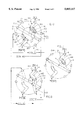
- FIG. 2 is a simplified exploded front isometric view of the selection valve of FIG. 1, with the rotor in a first position, for passing fluid through a column A.
- FIG. 3 is a view similar to that of FIG. 2, but with the rotor pivoted to a second position for flushing out the rotor and stator channels at the interface.
- FIG. 4 is a view similar to that of FIG. 2, but with the rotor turned to a third position, for passing fluid through a column B.
- FIG. 5 is a rear isometric view of the selection valve of FIG. 2.
- FIG. 6 is a simplified view looking rearwardly along the pivot axis, with the selection valve in the first position of FIG. 2.
- FIG. 7 is a view similar to that of FIG. 6, but with the selection valve in the second position, which is shown in FIG. 3.
- FIG. 8 is a view similar to that of FIG. 6, but with the selection valve in the third position, which is shown in FIG. 4.
- FIG. 9 is a simplified exploded front isometric view of a selection valve constructed in accordance with another embodiment of the invention, which enables flow through a selected one of three different external paths such as three different columns.
- FIG. 10 is a rear exploded isometric view of the selection valve of FIG. 9.
- FIG. 11 is a simplified axial view looking rearwardly along the pivot axis, of only the rotor of the selection valve of FIG. 9, with the rotor shown in a first position.
- FIG. 12 is a simplified axial view looking rearwardly along the pivot axis, showing the ports and channels of only the stator of the selection valve of FIG. 9.
- FIG. 13 is a simplified axial view looking rearwardly along the pivot axis, showing the rotor and stator of FIGS. 11 and 12 overlaid and in the first position, for fluid flow through column A.
- FIGS. 14, 15, and 16 are similar to those of FIGS. 11, 12, and 13, but with the rotor in a second position for flowing fluid through a column B.
- FIGS. 17, 18, and 19 are similar to those of FIGS. 14, 15, and 16, but with the rotor in a third position, to flow fluid through a column C.
- FIG. 1 illustrates a selection valve 10 of the present invention, which can receive a fluid sample to be analyzed and carrier fluid (e.g. saline solution), and which can divert the fluids through a selected one of different flow paths (e.g. through different chromatographic columns) and back through the selection valve to an analytical device.
- the selection valve includes a stator 12 comprising forward and rearward disc elements 14, 16 that are surrounded by a housing 20.
- the selection valve also includes a rotor 22 that includes a disc 24 and an extension 26 with an operator 28 that is usually motor operated but which can be manually operated. The operator 28 can be moved to turn the rotor about axis 30, between each of three different positions.
- Sensors or latches 32 are used to accurately position the rotor at each of the three rotational positions. A wide variety of known positioning mechanisms are available for this purpose.
- FIG. 2 is a simplified view of the stator 12 and rotor 22, showing ports and channels therein.
- the stator has six throughports labeled "1, 2, 3, 4, 5, and 6" which extend axially through the complete thickness of the stator. This is achieved by aligned through holes 40, 42 in the front and rear stator elements 14, 16.
- the rear element 16 has a pair of flush ports 7, 8 which are not aligned with any holes in the front element 14, but with the front ends of the ports 7, 8 connected together by a flush groove 44. All of the six throughports 1-6 extend completely through the stator, between the front face 46 of the front element and the rear face 48 of the rear element 16, with the adjacent faces 50, 52 of the stator elements being sealed to each other. For convenience, all six throughports 1-6 and the two additional ports 7, 8 lie on an imaginary port circle 54 which is centered on the axis 30.
- the rotor 22 has two rotor channels 60, 62 on its front face 64 which lies facewise adjacent to and is sealed to the stator rear face 48.
- Each of the channels such as 62 includes a radial groove portion or groove 70 with a port end 72 that lies on the port circle 54 (as seen in a view taken along the axis 30) to communicate with each of a plurality of stator ports as the rotor turns.
- Each channel also includes an arc groove portion or arc groove 74 which extends circumferentially with respect to the axis 30, along an arc circle 76.
- the arc circle 76 has a different diameter than the port circle 54, the particular arc circle 76 having a smaller diameter.
- Each arc groove has a free end 80 which is an end of the arc groove and of the channel lying furthest from the port end 72.
- the rear face 48 of the stator 12 has a pair of stator channels 90, 92 that each have radial groove portions or grooves 94 and arc groove portions or grooves 96.
- Each arc groove extends circumferentially about the arc circle 76 and has a free end 100.
- the radial groove 94 connects with the arc groove, and has a port end 102 that connects to one of the ports, the port end 102 being shown connected to the port 1.
- the radial groove 94 extends with a radial directional component so its opposite ends lie at different distances from the pivot axis.
- the arc grooves 96 of the stator channels overlap the arc grooves 74 of the rotor channels to connect them, and with no unswept volume being present.
- FIG. 2 shows the rotor in a first position, wherein it is used to pass carrier fluid (e.g. saline solution) and samples through a column 110 which is identified as "column A".
- carrier fluid e.g. saline solution
- column 110 which is identified as "column A”.
- a sample to be analyzed is entered into an injection valve or injector 111, as by the use of a syringe that injects the sample (at close to atmospheric pressure) into a chamber of the injector.
- a pump 112 pumps a carrier fluid through the injector 111, to pump the sample at high pressure into the front end of port 1.
- the fluid passes rearwardly entirely through the stator through port 1, and along the first stator channel 90 to the first rotor channel 60.
- the fluid passes along the first rotor channel 60 to its port end 72 and forwardly along the port 6.
- the fluid flows through column A and from column A to port 3.
- the fluid moves rearwardly completely through the stator along port 3 to the port end 72 of the second rotor channel 62.
- the fluid moves from the free end 80 of the rotor channel 62 into the second stator channel 92, and forwardly along port 4.
- the fluid exits the stator at port 4 and may flow into a detector 114.
- a chromatographic column such as 110 passes different components of a sample at different flow rates, so the least retained component exits the column first and reaches the detector 114 first, etc.
- FIG. 3 shows the injector after the rotor has been rotated by an angle A of 30° from its initial position of FIG. 2.
- the configuration of FIG. 3 is used to wash out the channels.
- the configuration of FIG. 3 can be used to flush out all flow paths in instrument, including the pump, injector, and detector without passing the flushout fluid through either column A or B (shown in FIG. 4, connected between ports 2 and 5). Columns A and B will frequently require different (potentially incompatible) carrier fluids in their use.
- changeover to the new carrier fluid can be accomplished without contaminating one column with carrier fluid used for the other and at velocities not possible when the fluid must pass through the highly restrictive and pressure sensitive columns.
- a flush solution or other fluid leaving pump 112 moves into port 1 of the selection valve (the injector 111 may contain no sample, or be switched so the fluid bypasses a sample-holding chamber).
- the fluid passes from port 1 through the first stator channel 90, through the first rotor channel 60, and forwardly along the stator port 8.
- the fluid moves diametrically along the flush groove 44, rearwardly along port 7, and into the second rotor channel 62.
- the fluid moves from the second rotor channel 62 to the second stator channel 92 which is connected to port 4 to exit from port 4.
- all channels and ports common to the configurations of FIGS. 2 and 4 are completely flushed.
- FIG. 4 shows a third configuration, wherein the rotor 22 has been turned by another angle B of 60°, from its initial position of FIG. 2.
- a sample from the injection valve or injector 111 passes rearwardly through port 1, along the first stator channel 90 into the first rotor channel 60, and forwardly along port 5 to another column 120 that is labeled "column B".
- Fluid from the column 120 passes rearwardly through port 2 into the second rotor channel 62 and from there to the second stator channel 92.
- the fluid moves from the second stator channel 72 forwardly through port 4 and out of port 4 to the detector 114.
- FIGS. 6-8 are simplified views showing the injector in the positions FIGS. 2-4, respectively.
- FIG. 6 shows the rotor in a position wherein the rotor channels 60, 62 are positioned to pass fluid through column A 110.
- the arc groove 74 of each rotor channel extends by an angle C of 60°, between its free end 80 and an opposite proximate arc groove end 130.
- the arc groove 74 has a specified width D, and it is assumed that each end of the arc groove is largely like a circle of that diameter D, with the angle C being taken from the middle of each arc groove end. In reality, the width D of the groove is very small with respect to its length.
- the rotor grooves 60, 62 are drawn to be of slightly smaller width than that of the stator grooves 90, 92, to aid in distinguishing them; in reality, they are preferably of the same widths.
- Each arc groove 96 of a stator channel 90, 92 extends by the angle C of 60°, by which the rotor grooves extend.
- the free end 80 of each rotor arc groove 74 overlaps part of the corresponding stator channel arc groove 96 at all rotational positions of the rotor.
- the free end 100 of each stator arc groove overlaps a corresponding rotor arc groove 74 at all rotational positions of the rotor.
- FIG. 8 is the most extreme position, but still shows that the free end 80 of the rotor arc groove 74 overlaps the free end 100 of the stator arc groove 96.
- Such unswept volume can also result in contamination of one column with potentially incompatible fluid used for the other column, since flushing would be incomplete in the flush position.
- Such unswept volume could be present if, for example, there were no arc groove 96 in FIG. 7, but instead the port 4 lay at the position 4X. In that case, the portion of the rotor arc groove 74 extending along the angle Y would constitute unswept volume in FIG. 7. It may be noted that it is possible to place some of the ports such as port 4 at a position other than on the port circle 54, such as at the position Z, although this is often not convenient.
- each arc grooves of each rotor channel and of each stator channel extend along substantially the entire angle of rotation of the rotor, which is 60° in the example given in FIGS. 1-8.
- the free end of each rotor and stator arc groove is directly connected to a location along the corresponding arc groove that it communicates with, to avoid an unswept volume.
- FIGS. 9 and 10 illustrate a selection valve 150 which enables the pumping of fluid through a selected one of three different columns 152, 154, and 156.
- the stator 160 includes two disc elements 162,164, with eight ports 1-8 extending completely through both discs.
- the rotor 168 has the same construction as the rotor of FIG. 2, in that it includes a pair of rotor channels 170, 172 that each has a radial groove 180 and an arc groove 184 that extends by 60° and that lies on an arc circle 186 that is of smaller diameter than a port circle 188, with both being centered on an axis of rotation 190. As shown in FIG.
- the stator rear disc element 164 has a pair of stator channels 200, 202, of the same construction as the stator channels 90, 92 of FIG. 5. That is, each stator channel has a stator arc groove 206 lying on the arc circle 186 and connected to a radial groove 204 that connects to one of the ports 1 or 5.
- the rear face 198 of the stator has four extension grooves 210, 212, 214, and 216 that connect to corresponding ports 2, 4, 6, and 8. The extension grooves are provided because, while the ports 1-8 are spaced apart by 45°, the rotor turns by 30° or 60° from its initial position.
- FIGS. 11-19 are simplified views taken along the axis 190, from the front of the selector valve. It can be seen in FIG. 11, which shows only the rotor 168, that the arc grooves 184 of the rotor channels each extends by an angle P of 60° about the pivot axis 190. FIG. 12 shows that the arc grooves 106 in the rear face 198 of the stator also extend by an angle P of 60°. Also, it can be seen that each of the ports such as 6 and 7 are spaced apart by an angle E of 45°. Each of the extension grooves 210 extends by an angle F of 15°, so that a free end 230 of an extension groove and an adjacent port 7 are spaced by an angle G of 30°, which is the angle of each step of the rotor.
- FIG. 13 shows the rotor of FIG. 11 and stator of FIG. 12 superimposed, in the initial position, wherein fluid flows through the first column 152.
- the port end 232 of each rotor channel 170, 172 is connected to the free end 230 of an extension groove 210.
- FIG. 16 shows a configuration wherein the rotor has been turned by an angle H of 30°, and its port end 232 is aligned directly with one of the ports 3.
- FIG. 19 shows the stator after it has been turned by an angle J of 60°.
- the port ends 232 of the rotor channels are connected to the free ends 230 of other extension grooves 212, 216 that extend from ports 6 and 2.
- the extension grooves 216, 214 extending from the two ports 2, 4 extend towards each other, so that even though the two ports 2, 4 are spaced apart by 90°, the free ends of their extension grooves are angularly spaced by 60°.
- the ports 1-8 lay on a port circle 54 having a diameter of 8 cm, and the arc grooves such as 74 lay on an arc circle 76 having a diameter of 4 cm.
- Each of the ports 1-8 and channels 60, 62, 90, 92 had a width of 0.25 mm.
- the invention provides a selection valve wherein the rotor can be turned through at least three different positions to direct fluid along three different flow paths, and yet there is substantially no unswept volume or "dead space" along the flow path within the injector for any of the positions. This is accomplished by providing channels in the front face of the rotor and in the rear face of the stator, where each channel has an arc groove that extends circumferentially about the pivot axis. Each arc groove extends far enough that the free end of each rotor arc groove is always directly (in an axial flow direction) open to the corresponding stator arc groove, and vice versa. This results in flow occurring through substantially all of each arc groove, to avoid a dead space where a sample or carrier fluid can accumulate.
- each rotor channel can be coupled to a corresponding port by provision of extension grooves in the rear face of the stator, that extend at least partially circumferentially from a port.
Abstract
Description
Claims (7)
Priority Applications (1)
| Application Number | Priority Date | Filing Date | Title |
|---|---|---|---|
| US08/660,872 US5803117A (en) | 1996-06-10 | 1996-06-10 | Multi-route full sweep selection valve |
Applications Claiming Priority (1)
| Application Number | Priority Date | Filing Date | Title |
|---|---|---|---|
| US08/660,872 US5803117A (en) | 1996-06-10 | 1996-06-10 | Multi-route full sweep selection valve |
Publications (1)
| Publication Number | Publication Date |
|---|---|
| US5803117A true US5803117A (en) | 1998-09-08 |
Family
ID=24651311
Family Applications (1)
| Application Number | Title | Priority Date | Filing Date |
|---|---|---|---|
| US08/660,872 Expired - Lifetime US5803117A (en) | 1996-06-10 | 1996-06-10 | Multi-route full sweep selection valve |
Country Status (1)
| Country | Link |
|---|---|
| US (1) | US5803117A (en) |
Cited By (40)
| Publication number | Priority date | Publication date | Assignee | Title |
|---|---|---|---|---|
| US6012487A (en) * | 1997-03-10 | 2000-01-11 | Brian A. Hauck | Prime purge injection valve or multi-route selections valve |
| US6012488A (en) * | 1998-09-17 | 2000-01-11 | Rheodyne, L.P. | Segmenting valve |
| US6267143B1 (en) | 1999-06-29 | 2001-07-31 | Upchurch Scientific, Inc. | Selection valve with ferrule cluster |
| WO2002042667A2 (en) * | 2000-11-24 | 2002-05-30 | Amersham Biosciences Ab | Rotary valve |
| US6632404B1 (en) | 2000-08-02 | 2003-10-14 | Symyx Technologies, Inc. | Automatically actuated parallel sample injector valve |
| US6662826B1 (en) | 2002-10-07 | 2003-12-16 | Abbott Laboratories | Liquid metering and transfer valve assembly with port switch |
| US6672336B2 (en) | 2001-11-28 | 2004-01-06 | Rheodyne, Lp | Dual random access, three-way rotary valve apparatus |
| US20040227123A1 (en) * | 2001-06-04 | 2004-11-18 | Rodgers Paul Justus | Fluid selection and redirection valve |
| US20050127097A1 (en) * | 2003-10-29 | 2005-06-16 | Rheodyne, Llc | Dosing engine and cartridge apparatus for liquid dispensing and method |
| US20060042686A1 (en) * | 2004-08-25 | 2006-03-02 | Controle Analytique Inc. | Rotary valve and analytical chromatographic system using the same |
| US20060090251A1 (en) * | 2004-11-01 | 2006-05-04 | Harbol Keith W | Fluid delivery system for a water tub using a removeable chemical carrier |
| US20080284160A1 (en) * | 2005-11-23 | 2008-11-20 | Jarl Voster | Coupling Device and a Method of Using Same |
| WO2008140377A1 (en) * | 2007-05-15 | 2008-11-20 | Ge Healthcare Bio-Sciences Ab | Random access rotary valve |
| US20100058841A1 (en) * | 2007-05-15 | 2010-03-11 | Ge Healthcare Bio-Sciences Ab | Flow distributing valve |
| WO2011000738A1 (en) * | 2009-06-30 | 2011-01-06 | Qiagen Gmbh | Valve |
| US20110240899A1 (en) * | 2008-11-13 | 2011-10-06 | Ge Healthcare Bio-Sciences Ab | Random access rotary valve |
| WO2011146861A1 (en) | 2010-05-20 | 2011-11-24 | Bio-Rad Laboratories, Inc. | Rotary column selector valve |
| WO2012027632A1 (en) | 2010-08-27 | 2012-03-01 | Waters Technologies Corporation | Variable-volume injection valve |
| WO2012036723A1 (en) * | 2010-09-15 | 2012-03-22 | Gulf Sea Ventures LLC | Fluid-directing multiport rotary valve |
| US20120073665A1 (en) * | 2008-12-04 | 2012-03-29 | Neil Picha | Methods and Apparatus for Moving Aliquot Samples of Fluid |
| WO2013043519A1 (en) * | 2011-09-21 | 2013-03-28 | Affluidx, Llc | Multi-mode injection valve |
| US20130174927A1 (en) * | 2012-01-09 | 2013-07-11 | Promochrom Technologies Ltd. | Fluid selection valve |
| US20140026994A1 (en) * | 2012-07-26 | 2014-01-30 | Richard N. Codos | Fluid sensing and distributing apparatus |
| US20150090345A1 (en) * | 2012-04-27 | 2015-04-02 | Ge Healthcare Biosciences Ab | Rotary selection valve |
| US9193996B2 (en) | 2012-04-03 | 2015-11-24 | Illumina, Inc. | Integrated optoelectronic read head and fluidic cartridge useful for nucleic acid sequencing |
| DE102015112397A1 (en) | 2014-07-29 | 2016-02-04 | Idex Health&Science Llc | Mehrwegewählventil |
| CN105324665A (en) * | 2013-04-22 | 2016-02-10 | 积水医疗株式会社 | Switching valve for flow-type analysis device |
| CN105829884A (en) * | 2013-12-19 | 2016-08-03 | 通用电气健康护理生物科学股份公司 | Rotary valve |
| US20160273664A1 (en) * | 2013-10-31 | 2016-09-22 | Ge Healthcare Bio-Sciences Ab | Cleaning of rotary valves |
| US9541207B1 (en) * | 2014-02-03 | 2017-01-10 | Elemental Scientific, Inc. | Valve assembly with bottom bypass ports |
| US20180224006A1 (en) * | 2017-02-03 | 2018-08-09 | Micromeritics Instrument Corporation | Blend valve |
| CN108426063A (en) * | 2017-02-13 | 2018-08-21 | 奥托埃格尔霍夫两合公司 | Multi-way valve for controlling refrigerant circuit |
| EP3376222A1 (en) | 2017-03-16 | 2018-09-19 | Biotage AB | Baseline correction for liquid chromatography / mass spectroscopy |
| US10386342B2 (en) | 2008-01-25 | 2019-08-20 | Dionex Softron Gmbh | Sample injector for liquid chromatography, particularly for high performance liquid chromatography |
| US10473631B2 (en) | 2015-06-25 | 2019-11-12 | Dionex Softron Gmbh | Sampler for liquid chromatography |
| US10634652B2 (en) | 2016-01-29 | 2020-04-28 | Dionex Softron Gmbh | Sample pre-compression valve for liquid chromatography |
| US10746708B2 (en) | 2015-03-30 | 2020-08-18 | Ge Healthcare Bio-Sciences Ab | Rotary valve and a chromatography system |
| US11204306B2 (en) * | 2018-08-10 | 2021-12-21 | Elemental Scientific, Inc. | Preconcentration of fluid samples with alternating dual loop introduction |
| US11307181B1 (en) * | 2018-07-14 | 2022-04-19 | Sielc Technologies Corporation | HPLC system with mixed-mode columns for measuring charged analytes in complex mixtures |
| US11441978B1 (en) * | 2018-04-12 | 2022-09-13 | Elemental Scientific, Inc. | Automatic evaporative sample preparation |
Citations (8)
| Publication number | Priority date | Publication date | Assignee | Title |
|---|---|---|---|---|
| US2719426A (en) * | 1952-04-23 | 1955-10-04 | Gen Electric | Apparatus for measuring gas pressure in sealed vessels |
| US2751034A (en) * | 1952-10-17 | 1956-06-19 | Adsorption Res Corp | Fluid treating apparatus |
| US2918938A (en) * | 1954-03-23 | 1959-12-29 | Sylvania Electric Prod | Valve construction |
| US3040777A (en) * | 1959-04-10 | 1962-06-26 | Universal Oil Prod Co | Rotary valve |
| US3198004A (en) * | 1962-10-12 | 1965-08-03 | Borden Co | Can testing valve |
| US3422848A (en) * | 1966-06-09 | 1969-01-21 | Universal Oil Prod Co | Multiport rotary disc valve with liner protection means |
| US4552178A (en) * | 1982-04-07 | 1985-11-12 | Scanpump Ab | Variable fluid flow restricting throttle |
| US5010921A (en) * | 1989-07-17 | 1991-04-30 | Spectra-Physics, Inc. | Nonsymmetrical valve |
-
1996
- 1996-06-10 US US08/660,872 patent/US5803117A/en not_active Expired - Lifetime
Patent Citations (8)
| Publication number | Priority date | Publication date | Assignee | Title |
|---|---|---|---|---|
| US2719426A (en) * | 1952-04-23 | 1955-10-04 | Gen Electric | Apparatus for measuring gas pressure in sealed vessels |
| US2751034A (en) * | 1952-10-17 | 1956-06-19 | Adsorption Res Corp | Fluid treating apparatus |
| US2918938A (en) * | 1954-03-23 | 1959-12-29 | Sylvania Electric Prod | Valve construction |
| US3040777A (en) * | 1959-04-10 | 1962-06-26 | Universal Oil Prod Co | Rotary valve |
| US3198004A (en) * | 1962-10-12 | 1965-08-03 | Borden Co | Can testing valve |
| US3422848A (en) * | 1966-06-09 | 1969-01-21 | Universal Oil Prod Co | Multiport rotary disc valve with liner protection means |
| US4552178A (en) * | 1982-04-07 | 1985-11-12 | Scanpump Ab | Variable fluid flow restricting throttle |
| US5010921A (en) * | 1989-07-17 | 1991-04-30 | Spectra-Physics, Inc. | Nonsymmetrical valve |
Cited By (86)
| Publication number | Priority date | Publication date | Assignee | Title |
|---|---|---|---|---|
| US6012487A (en) * | 1997-03-10 | 2000-01-11 | Brian A. Hauck | Prime purge injection valve or multi-route selections valve |
| US6012488A (en) * | 1998-09-17 | 2000-01-11 | Rheodyne, L.P. | Segmenting valve |
| US6267143B1 (en) | 1999-06-29 | 2001-07-31 | Upchurch Scientific, Inc. | Selection valve with ferrule cluster |
| US6390127B2 (en) * | 1999-06-29 | 2002-05-21 | Upchurch Scientific, Inc. | Selection valve with ferrule cluster |
| US6632404B1 (en) | 2000-08-02 | 2003-10-14 | Symyx Technologies, Inc. | Automatically actuated parallel sample injector valve |
| US6969045B2 (en) | 2000-11-24 | 2005-11-29 | Amersham Biosciences Ab | Rotary valve |
| WO2002042667A2 (en) * | 2000-11-24 | 2002-05-30 | Amersham Biosciences Ab | Rotary valve |
| WO2002042667A3 (en) * | 2000-11-24 | 2002-08-15 | Amersham Biosciences Ab | Rotary valve |
| US20040021113A1 (en) * | 2000-11-24 | 2004-02-05 | Owe Salven | Rotary valve |
| US20040227123A1 (en) * | 2001-06-04 | 2004-11-18 | Rodgers Paul Justus | Fluid selection and redirection valve |
| US6672336B2 (en) | 2001-11-28 | 2004-01-06 | Rheodyne, Lp | Dual random access, three-way rotary valve apparatus |
| US6662826B1 (en) | 2002-10-07 | 2003-12-16 | Abbott Laboratories | Liquid metering and transfer valve assembly with port switch |
| US8431020B2 (en) | 2003-10-29 | 2013-04-30 | Idex Health & Science Llc | Dosing engine and cartridge apparatus for liquid dispensing and method |
| US20090266751A1 (en) * | 2003-10-29 | 2009-10-29 | Idex Health & Science Llc | Dosing engine and cartridge apparatus for liquid dispensing and method |
| US20050127097A1 (en) * | 2003-10-29 | 2005-06-16 | Rheodyne, Llc | Dosing engine and cartridge apparatus for liquid dispensing and method |
| US7544289B2 (en) | 2003-10-29 | 2009-06-09 | Idex Health & Science Llc | Dosing engine and cartridge apparatus for liquid dispensing and method |
| US20060042686A1 (en) * | 2004-08-25 | 2006-03-02 | Controle Analytique Inc. | Rotary valve and analytical chromatographic system using the same |
| US7503203B2 (en) | 2004-08-25 | 2009-03-17 | Mecanique Analytique Inc. | Rotary valve and analytical chromatographic system using the same |
| US20060090251A1 (en) * | 2004-11-01 | 2006-05-04 | Harbol Keith W | Fluid delivery system for a water tub using a removeable chemical carrier |
| US7258783B2 (en) | 2004-11-01 | 2007-08-21 | Watkins Manufacturing Corporation | Fluid delivery system for a water tub using a removeable chemical carrier |
| US20080284160A1 (en) * | 2005-11-23 | 2008-11-20 | Jarl Voster | Coupling Device and a Method of Using Same |
| US20100058841A1 (en) * | 2007-05-15 | 2010-03-11 | Ge Healthcare Bio-Sciences Ab | Flow distributing valve |
| US20100127200A1 (en) * | 2007-05-15 | 2010-05-27 | Patrik Kallback | Random access rotary valve |
| WO2008140377A1 (en) * | 2007-05-15 | 2008-11-20 | Ge Healthcare Bio-Sciences Ab | Random access rotary valve |
| US8225817B2 (en) * | 2007-05-15 | 2012-07-24 | Ge Healthcare Bio-Sciences Ab | Flow distributing valve |
| US8286663B2 (en) | 2007-05-15 | 2012-10-16 | Ge Healthcare Bio-Sciences Ab | Random access rotary valve |
| US11156589B2 (en) | 2008-01-25 | 2021-10-26 | Dionex Softron Gmbh | Sample injector for liquid chromatography, particularly for high performance liquid chromatography |
| US10386342B2 (en) | 2008-01-25 | 2019-08-20 | Dionex Softron Gmbh | Sample injector for liquid chromatography, particularly for high performance liquid chromatography |
| US11802854B2 (en) | 2008-01-25 | 2023-10-31 | Dionex Softron Gmbh | Sample injector for liquid chromatography, particularly for high performance liquid chromatography |
| US8770226B2 (en) * | 2008-11-13 | 2014-07-08 | Ge Healthcare Bio-Sciences Ab | Random access rotary valve |
| US20110240899A1 (en) * | 2008-11-13 | 2011-10-06 | Ge Healthcare Bio-Sciences Ab | Random access rotary valve |
| US20120073665A1 (en) * | 2008-12-04 | 2012-03-29 | Neil Picha | Methods and Apparatus for Moving Aliquot Samples of Fluid |
| US9133833B2 (en) * | 2008-12-04 | 2015-09-15 | Alltech Associates, Inc. | Methods and apparatus for moving aliquot samples of fluid |
| WO2011000738A1 (en) * | 2009-06-30 | 2011-01-06 | Qiagen Gmbh | Valve |
| US8887754B2 (en) | 2009-06-30 | 2014-11-18 | Qiagen Gmbh | Valve |
| JP2013533464A (en) * | 2010-05-20 | 2013-08-22 | バイオ−ラッド ラボラトリーズ,インコーポレイティド | Rotating cylindrical switching valve |
| US8656955B2 (en) | 2010-05-20 | 2014-02-25 | Bio-Rad Laboratories, Inc. | Rotary column selector valve |
| KR101418666B1 (en) * | 2010-05-20 | 2014-07-14 | 바이오 래드 래버러토리스 인코오포레이티드 | Rotary column selector valve |
| CN102918309B (en) * | 2010-05-20 | 2014-07-30 | 生物辐射实验室股份有限公司 | Rotary column selector valve |
| CN102918309A (en) * | 2010-05-20 | 2013-02-06 | 生物辐射实验室股份有限公司 | Rotary column selector valve |
| WO2011146861A1 (en) | 2010-05-20 | 2011-11-24 | Bio-Rad Laboratories, Inc. | Rotary column selector valve |
| US9115815B2 (en) | 2010-08-27 | 2015-08-25 | Waters Technologies Corporation | Variable-volume injection valve |
| WO2012027632A1 (en) | 2010-08-27 | 2012-03-01 | Waters Technologies Corporation | Variable-volume injection valve |
| WO2012036723A1 (en) * | 2010-09-15 | 2012-03-22 | Gulf Sea Ventures LLC | Fluid-directing multiport rotary valve |
| US8960231B2 (en) | 2011-09-21 | 2015-02-24 | Neil Robert Picha | Multi-mode injection valve |
| WO2013043519A1 (en) * | 2011-09-21 | 2013-03-28 | Affluidx, Llc | Multi-mode injection valve |
| US8813785B2 (en) * | 2012-01-09 | 2014-08-26 | Promochrom Technologies Ltd. | Fluid selection valve |
| US20130174927A1 (en) * | 2012-01-09 | 2013-07-11 | Promochrom Technologies Ltd. | Fluid selection valve |
| US11565267B2 (en) | 2012-04-03 | 2023-01-31 | Illumina, Inc. | Integrated optoelectronic read head and fluidic cartridge useful for nucleic acid sequencing |
| US10549281B2 (en) | 2012-04-03 | 2020-02-04 | Illumina, Inc. | Integrated optoelectronic read head and fluidic cartridge useful for nucleic acid sequencing |
| US9193996B2 (en) | 2012-04-03 | 2015-11-24 | Illumina, Inc. | Integrated optoelectronic read head and fluidic cartridge useful for nucleic acid sequencing |
| US9650669B2 (en) | 2012-04-03 | 2017-05-16 | Illumina, Inc. | Integrated optoelectronic read head and fluidic cartridge useful for nucleic acid sequencing |
| US20150090345A1 (en) * | 2012-04-27 | 2015-04-02 | Ge Healthcare Biosciences Ab | Rotary selection valve |
| US20140026994A1 (en) * | 2012-07-26 | 2014-01-30 | Richard N. Codos | Fluid sensing and distributing apparatus |
| US9841406B2 (en) | 2013-04-22 | 2017-12-12 | Sekisui Medical Co., Ltd. | Switching valve for flow type analysis apparatus |
| CN105324665A (en) * | 2013-04-22 | 2016-02-10 | 积水医疗株式会社 | Switching valve for flow-type analysis device |
| CN105324665B (en) * | 2013-04-22 | 2017-10-13 | 积水医疗株式会社 | The switching valve of flow cytometer showed equipment |
| US10571033B2 (en) * | 2013-10-31 | 2020-02-25 | Ge Healthcare Bio-Sciences Ab | Cleaning of rotary valves |
| US9845894B2 (en) * | 2013-10-31 | 2017-12-19 | Ge Healthcare Bio-Sciences Ab | Cleaning of rotary valves |
| US20180106388A1 (en) * | 2013-10-31 | 2018-04-19 | Ge Healthcare Bio-Sciences Ab | Cleaning of rotary valves |
| US20160273664A1 (en) * | 2013-10-31 | 2016-09-22 | Ge Healthcare Bio-Sciences Ab | Cleaning of rotary valves |
| CN105829884A (en) * | 2013-12-19 | 2016-08-03 | 通用电气健康护理生物科学股份公司 | Rotary valve |
| CN105829884B (en) * | 2013-12-19 | 2019-03-08 | 通用电气健康护理生物科学股份公司 | Rotary valve |
| US9541207B1 (en) * | 2014-02-03 | 2017-01-10 | Elemental Scientific, Inc. | Valve assembly with bottom bypass ports |
| US10060541B1 (en) | 2014-02-03 | 2018-08-28 | Elemental Scientific, Inc. | Valve assembly with bottom bypass ports |
| US9739383B2 (en) | 2014-07-29 | 2017-08-22 | Idex Health & Science Llc | Multi-path selector valve |
| GB2529312B (en) * | 2014-07-29 | 2020-09-09 | Idex Health & Science Llc | Multi-Path Selector Valve |
| DE102015112397A1 (en) | 2014-07-29 | 2016-02-04 | Idex Health&Science Llc | Mehrwegewählventil |
| GB2529312A (en) * | 2014-07-29 | 2016-02-17 | Idex Health & Science Llc | Multi-Path Selector Valve |
| US10746708B2 (en) | 2015-03-30 | 2020-08-18 | Ge Healthcare Bio-Sciences Ab | Rotary valve and a chromatography system |
| US11867669B2 (en) | 2015-06-25 | 2024-01-09 | Dionex Softron Gmbh | Sampler for liquid chromatography |
| US10473631B2 (en) | 2015-06-25 | 2019-11-12 | Dionex Softron Gmbh | Sampler for liquid chromatography |
| US11307178B2 (en) | 2015-06-25 | 2022-04-19 | Dionex Softron Gmbh | Sampler for liquid chromatography |
| US11543391B2 (en) | 2016-01-29 | 2023-01-03 | Dionex Softron Germering | Sample pre-compression valve for liquid chromatography |
| US11156590B2 (en) | 2016-01-29 | 2021-10-26 | Dionex Softron Gmbh | Sample pre-compression valve for liquid chromatography |
| US10634652B2 (en) | 2016-01-29 | 2020-04-28 | Dionex Softron Gmbh | Sample pre-compression valve for liquid chromatography |
| US11733214B2 (en) | 2016-01-29 | 2023-08-22 | Dionex Softron Gmbh | Sample pre-compression valve for liquid chromatography |
| US20180224006A1 (en) * | 2017-02-03 | 2018-08-09 | Micromeritics Instrument Corporation | Blend valve |
| US10487954B2 (en) * | 2017-02-03 | 2019-11-26 | Micromeritics Instrument Corporation | Blend valve |
| CN108426063B (en) * | 2017-02-13 | 2021-12-10 | 奥托埃格尔霍夫两合公司 | Multi-way valve for controlling a refrigerant circuit |
| US10619899B2 (en) * | 2017-02-13 | 2020-04-14 | Otto Egelhof Gmbh & Co. Kg | Multiway valve for controlling a refrigerant circuit |
| CN108426063A (en) * | 2017-02-13 | 2018-08-21 | 奥托埃格尔霍夫两合公司 | Multi-way valve for controlling refrigerant circuit |
| EP3376222A1 (en) | 2017-03-16 | 2018-09-19 | Biotage AB | Baseline correction for liquid chromatography / mass spectroscopy |
| US11441978B1 (en) * | 2018-04-12 | 2022-09-13 | Elemental Scientific, Inc. | Automatic evaporative sample preparation |
| US11307181B1 (en) * | 2018-07-14 | 2022-04-19 | Sielc Technologies Corporation | HPLC system with mixed-mode columns for measuring charged analytes in complex mixtures |
| US11204306B2 (en) * | 2018-08-10 | 2021-12-21 | Elemental Scientific, Inc. | Preconcentration of fluid samples with alternating dual loop introduction |
Similar Documents
| Publication | Publication Date | Title |
|---|---|---|
| US5803117A (en) | Multi-route full sweep selection valve | |
| US6012487A (en) | Prime purge injection valve or multi-route selections valve | |
| US8286663B2 (en) | Random access rotary valve | |
| EP0481285B1 (en) | Apparatus for multi-path flow regulation | |
| US8186381B2 (en) | Selection valve | |
| EP2113081B1 (en) | Rotation valve for sample injection | |
| US8770226B2 (en) | Random access rotary valve | |
| JP5377477B2 (en) | Flow distribution valve | |
| US10113995B2 (en) | Multi-position, micro-fluidic valve assembly with multiple radial grooves to enable individual or combined flows | |
| US6012488A (en) | Segmenting valve | |
| US4068528A (en) | Two position rotary valve for injecting sample liquids into an analysis system | |
| US20070251302A1 (en) | Flow path switching valve, high performance liquid chromatography using the same and analytical method thereof | |
| US9739383B2 (en) | Multi-path selector valve | |
| US4896546A (en) | Liquid metering and transfer valve assembly | |
| EP1394539A1 (en) | Multiport switching valve for a liquid flow system | |
| CN211513510U (en) | Quantitative ring and chromatographic column combined device | |
| EP1332351B1 (en) | Multiple input flow cell with single fluid path | |
| CN116601487A (en) | Fluid rotary valve | |
| JPH04301565A (en) | Sample injector for two-channel injection | |
| JPH04301564A (en) | Sample injector for two-channel injection |
Legal Events
| Date | Code | Title | Description |
|---|---|---|---|
| AS | Assignment |
Owner name: RHEODYNE, L.P., CALIFORNIA Free format text: ASSIGNMENT OF ASSIGNORS INTEREST;ASSIGNORS:OLSEN, KRISTINE;HAUCK, BRIAN;REEL/FRAME:008044/0337 Effective date: 19960605 |
|
| AS | Assignment |
Owner name: CREDITANSTALT CORPORATE FINANCE, INC., CONNECTICUT Free format text: SECURITY AGREEMENT;ASSIGNOR:RHEODYNE, L.P.;REEL/FRAME:009168/0405 Effective date: 19980218 |
|
| STCF | Information on status: patent grant |
Free format text: PATENTED CASE |
|
| AS | Assignment |
Owner name: WELLS FARGO BANK, NATIONAL ASSOCIATION, CALIFORNIA Free format text: SECURITY AGREEMENT;ASSIGNOR:RHEODYNE, L.P.;REEL/FRAME:011077/0884 Effective date: 20000831 |
|
| FPAY | Fee payment |
Year of fee payment: 4 |
|
| AS | Assignment |
Owner name: RHEODYNE, L.P., CALIFORNIA Free format text: RELEASE BY SECURED PARTY;ASSIGNOR:CREDITANSTALT CORPORATE FINANCE, INC.;REEL/FRAME:013056/0393 Effective date: 19980218 |
|
| AS | Assignment |
Owner name: RHEODYNE, L.P., CALIFORNIA Free format text: TERMINATION OF SECURITY AGREEMENT;ASSIGNOR:WELLS FARGO BANK NATIONAL ASSOCIATION;REEL/FRAME:013101/0498 Effective date: 20020718 |
|
| AS | Assignment |
Owner name: RHEODYNE ACQUISITION CORP., CALIFORNIA Free format text: MERGER;ASSIGNOR:RHEODYNE, L.P.;REEL/FRAME:013417/0748 Effective date: 20020731 |
|
| AS | Assignment |
Owner name: RHEODYNE LLC, CALIFORNIA Free format text: CHANGE OF NAME;ASSIGNOR:RHEODYNE ACQUISITION CORP.;REEL/FRAME:013506/0153 Effective date: 20020719 |
|
| FEPP | Fee payment procedure |
Free format text: PAT HOLDER NO LONGER CLAIMS SMALL ENTITY STATUS, ENTITY STATUS SET TO UNDISCOUNTED (ORIGINAL EVENT CODE: STOL); ENTITY STATUS OF PATENT OWNER: LARGE ENTITY |
|
| FEPP | Fee payment procedure |
Free format text: PAYOR NUMBER ASSIGNED (ORIGINAL EVENT CODE: ASPN); ENTITY STATUS OF PATENT OWNER: LARGE ENTITY |
|
| FPAY | Fee payment |
Year of fee payment: 8 |
|
| FEPP | Fee payment procedure |
Free format text: PAYER NUMBER DE-ASSIGNED (ORIGINAL EVENT CODE: RMPN); ENTITY STATUS OF PATENT OWNER: LARGE ENTITY Free format text: PAYOR NUMBER ASSIGNED (ORIGINAL EVENT CODE: ASPN); ENTITY STATUS OF PATENT OWNER: LARGE ENTITY |
|
| AS | Assignment |
Owner name: IDEX HEALTH & SCIENCE LLC, ILLINOIS Free format text: CHANGE OF NAME;ASSIGNOR:RHEODYNE LLC;REEL/FRAME:022703/0849 Effective date: 20081218 |
|
| FPAY | Fee payment |
Year of fee payment: 12 |