US5800467A - Cardio-synchronous impedance measurement system for an implantable stimulation device - Google Patents
Cardio-synchronous impedance measurement system for an implantable stimulation device Download PDFInfo
- Publication number
- US5800467A US5800467A US08/766,641 US76664196A US5800467A US 5800467 A US5800467 A US 5800467A US 76664196 A US76664196 A US 76664196A US 5800467 A US5800467 A US 5800467A
- Authority
- US
- United States
- Prior art keywords
- impedance
- heart
- pulses
- control means
- slope
- Prior art date
- Legal status (The legal status is an assumption and is not a legal conclusion. Google has not performed a legal analysis and makes no representation as to the accuracy of the status listed.)
- Expired - Lifetime
Links
Images


Classifications
-
- A—HUMAN NECESSITIES
- A61—MEDICAL OR VETERINARY SCIENCE; HYGIENE
- A61N—ELECTROTHERAPY; MAGNETOTHERAPY; RADIATION THERAPY; ULTRASOUND THERAPY
- A61N1/00—Electrotherapy; Circuits therefor
- A61N1/18—Applying electric currents by contact electrodes
- A61N1/32—Applying electric currents by contact electrodes alternating or intermittent currents
- A61N1/36—Applying electric currents by contact electrodes alternating or intermittent currents for stimulation
- A61N1/362—Heart stimulators
- A61N1/365—Heart stimulators controlled by a physiological parameter, e.g. heart potential
- A61N1/36514—Heart stimulators controlled by a physiological parameter, e.g. heart potential controlled by a physiological quantity other than heart potential, e.g. blood pressure
- A61N1/36521—Heart stimulators controlled by a physiological parameter, e.g. heart potential controlled by a physiological quantity other than heart potential, e.g. blood pressure the parameter being derived from measurement of an electrical impedance
-
- A—HUMAN NECESSITIES
- A61—MEDICAL OR VETERINARY SCIENCE; HYGIENE
- A61N—ELECTROTHERAPY; MAGNETOTHERAPY; RADIATION THERAPY; ULTRASOUND THERAPY
- A61N1/00—Electrotherapy; Circuits therefor
- A61N1/18—Applying electric currents by contact electrodes
- A61N1/32—Applying electric currents by contact electrodes alternating or intermittent currents
- A61N1/36—Applying electric currents by contact electrodes alternating or intermittent currents for stimulation
- A61N1/362—Heart stimulators
- A61N1/365—Heart stimulators controlled by a physiological parameter, e.g. heart potential
- A61N1/368—Heart stimulators controlled by a physiological parameter, e.g. heart potential comprising more than one electrode co-operating with different heart regions
- A61N1/3682—Heart stimulators controlled by a physiological parameter, e.g. heart potential comprising more than one electrode co-operating with different heart regions with a variable atrioventricular delay
Definitions
- the present invention relates to implantable electrical devices and, more particularly, concerns a system for use with the heart for optimizing heart performance by measuring the impedance within the heart synchronously with the detection of a ventricular contraction.
- Implantable electrical devices are increasingly used in patients for therapy for various physical ailments.
- one very common type of implantable electrical device is the pacemaker.
- a pacemaker is an implantable electrical device that has leads that are positioned within the heart so that therapeutic shocks can be provided to the heart to regulate heart function. Since their initial use, pacemakers have become increasingly sophisticated to the point where pacemakers are capable of sensing the function of the heart and providing therapeutic shocks that are both configured and timed to optimize the pumping function of the heart.
- the efficiency of the heart in pumping blood can be varied.
- the timing of a therapeutic shock applied to the heart from a pacemaker can also vary the AV delay and/or the PV delay, i.e., the delay between the contraction of the atrium and the ventricle, to also improve the efficiency of the pumping function of the heart.
- pacemakers have become sufficiently sophisticated to be able to time the therapeutic shocks being applied to the heart to vary these two parameters, the ability to do so requires that there be various sensors positioned within the heart that provide the controller of the pacemaker information indicative of the function of the heart.
- the pacemaker lead that is positioned within the ventricle provides an electrocardiogram signal to the pacemaker controller that is indicative of the electrical stimulation and contraction of the heart. This signal can be used by the controller to determine when pacing therapeutic shocks are needed.
- the measured impedance of the heart within the ventricle also provides an indication as to the contractility of the heart. Contractility is the degree of contraction that the heart is experiencing during its pumping function. It is well understood that the greater contractility of the heart, the greater volume of blood being pumped by the heart for any given heart rate.
- the impedance measured within the ventricle during contraction increases contemporaneously with the increase in pressure within the contracting ventricle. Consequently, it is understood that by measuring the impedance within the ventricle, an indication as to the contractility can be provided to the controller.
- This information can be used by the controller for a number of purposes such as adjusting the AV delay and pacing rate to optimize the heart's pumping function.
- impedance within the right ventricle of the heart, requires that electrical energy be transmitted into the ventricle of the heart so that the impedance can then be calculated.
- current is applied between the tip or the ring and the pacemaker case, so that the impedance can be measured therebetween.
- U.S. Pat. No. 5,003,976, U.S. Pat. No. 4,919,136 and U.S. Pat. No. 4,901,725 disclose measuring the impedance signal between the ring/tip electrode and the pacemaker case with an alternating current source applied therebetween.
- the impedance signal is measured between the tip electrode and the pacemaker case with the current source being applied between a ring electrode and the pacemaker case.
- the impedance measurement compromises the longevity of the battery that is powering the pacemaker device.
- current is drained out of the battery, simply for the purpose of measuring the impedance. This drain on the battery, of course, reduces the longevity of the battery and, therefore, reduces the longevity of the device itself.
- the system of the present invention which is comprised of an implantable electrical device having at least one lead positioned within a contracting chamber of the heart.
- the implantable electrical device should also receive signals from a sensor indicative of the occurrence of a spontaneous R-wave of the heart or a paced beat of the heart. Subsequently, the system then applies current to the lead so as to obtain an impedance signal at at least two points during a window of time following the R-wave or paced beat during which contraction of the chamber of the heart occurs.
- the system uses the at least two measured impedances to calculate the slope of the change in impedance (dz/dt) of the heart during this interval.
- the Applicant has determined that the slope of change of impedance measured during a time interval around late rapid ventricular ejection and early reduced ejection is strongly correlated to the maximum slope of the ventricular pressure of the ventricular ejection. In the preferred embodiment, only a single slope measurement is made (e.g., using two or three impedance measurements) during this window wherein each impedance measurement is taken, for example, at a 64 Hz sampling rate, to achieve two measurements approximately 15.6 milliseconds apart.
- the Applicant has determined that the biological correlation between the impedance slope and the maximum slope of the ventricular pressure under sinus conditions and also under pacing conditions is very high. This signal can therefore be used as an indication as to the contractility of the heart.
- This indication can then be used by the system to alter the performance of the pacemaker to optimize the function of the heart.
- the parameter can be used for purposes such as rate adaptive pacing, altering AV delay, or altering the selected pacing rate of the heart so that the volume of blood pumped by the heart is maximized for each heartbeat.
- the impedance parameter can be obtained by injecting current down the lead at at least two discrete time periods as opposed to measuring the impedance over the entire waveform.
- FIG. 1 is a block diagram illustrating the functional components of a pacemaker system of the preferred embodiment
- FIG. 2 is an isometric view of a heart having the pacemaker system of FIG. 1 implanted therein;
- FIG. 3 is a diagram of a typical ventricular impedance waveform illustrating when impedance measurement signals are obtained by the system of FIG. 1;
- FIG. 4 is a diagram which illustrates the correlation between the maximum slope change in pressure during ventricular ejection and the slope change in impedance dz/dt during hemodynamic intervention;
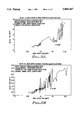
- FIGS. 5A and 5B are diagrams illustrating the correlation between dz/dt versus maximum dp/dt during ventricular ejection for five canines with hemodynamic intervention.
- FIG. 6 is an exemplary flow chart illustrating the operation of the system of FIG. 1.
- FIG. 1 is a schematic illustration of a pacing system 100 that is used to regulate the function of a heart 102.
- the pacing system 100 includes a controller 101 that comprises a processor 104 that receives signals from a sensor 106 via a sensor circuit 110 which are indicative of the function of the heart 102.
- the sensor 106 is typically comprised of a pacing lead 40 that is implanted into an apex 140 of a right ventricle 142 of the heart.
- the processor 104 can trigger a timing and control circuit 112 and a pulse generator circuit 114 to apply therapeutic shocks, i.e., electrical impulses, to the heart 102 via one or more leads positioned within the heart 102 for pacing purposes.
- therapeutic shocks i.e., electrical impulses
- the pacing system 100 is also configured so as to have a telemetry circuit 122 wherein information stored in the memory 120 can be downloaded to an external programmer 124 and instructions from the external programmer 124 can be provided to the processor 104 in a manner well known in the art.
- the operation of the controller 101 and the pacing system 100 in this respect is typical of the operation of known prior art pacing systems.
- the pacing system 100 in this embodiment also includes an impedance sensing circuit 125 that makes periodic determinations of the impedance within the right ventricle of the heart in response to signals from the processor 104.
- the processor 104 periodically triggers the pulse generator 114 to transmit a current pulse into the heart via one of the electrodes positioned within the heart.
- the pulse generator 114 is generally a constant voltage pulse generator for purposes of generating stimulation pulses, for convenience, the present invention describes the pulse generator 114 to include circuitry for constant current measurement pulses. Alternatively, the constant current measurement pulses could have been shown as a separate block.
- the voltage is then measured by the impedance sensing circuit 125 and the instantaneous impedance is then calculated. These calculated values can then be used to obtain an impedance slope dz/dt in the manner that will be described in greater detail hereinbelow.
- FIG. 2 illustrates the heart 102 with a single-pass pacing lead 40 with a ventricular electrode ventricular electrode tip 41 positioned within the right ventricle 142 of the heart 102.
- a pacing lead 40 has an electrode tip 43 which is positioned within the right atrium 152 of the heart 102.
- a single-pass lead 40 is shown in FIG. 2, this is for illustration purposes only, and one of ordinary skill in the art could easily replace this lead for two leads, either unipolar or bipolar, and not depart from the spirit of the invention.
- at least one lead is required located in the ventricle.
- the pacing lead 40 is preferably coupled to a case electrode 160 that is positioned within the body of the patient, such as under the pectoral muscle in a pectoral implant device.
- the processor 104 and the other related circuitry is positioned within the case electrode 160.
- the ventricular electrode ventricular electrode tip 41 acts as the sensor 106 and provides signals to the processor 104 via the sensing circuit 110 that are indicative of the functions of the heart.
- the sensor 106 provides signals to the processor which comprise an intracardiac electrogram.
- the processor 104 receives signals which are indicative of the depolarization of the cardiac cells of the heart. Based upon these signals, the processor 104 can determine whether therapeutic shocks need to be applied to the heart to regulate heart function. Further, in the embodiment shown in FIGS. 1 and 2, both the right ventricle electrodes 41, 44 and the right atrial electrodes 43, 45 can be used to provide the unipolar or bipolar sense information to the sensor circuit indicative of the functioning of the heart (e.g., cardiac electrical signals). The operation of the pacing system 100 is, in this respect, similar to the operation of pacemakers of the prior art.
- the pacing system 100 which includes the impedance sensing circuit 125, obtains an impedance slope which is indicative of the contractility of the heart in the following manner.
- the processor 104 receives a signal from the sensor circuit 110 which is indicative of the occurrence of a R-wave or a pacing pulse applied to the heart 102.
- the processor 104 waits until a measurement window occurs during ventricular ejection, i.e., contraction of the right ventricle of the heart. More particularly, the measurement window occurs during late rapid ventricular ejection and early reduced ejection.
- the processor 104 triggers the timing and control circuitry 112 and the pulse generator 114 to provide a current pulse, preferably, to the ventricular electrode ring 44, or (if a unipolar lead is used) the ventricular electrode ventricular electrode tip 41.
- the impedance sensing circuit 125 measures the voltage drop between two electrodes, for example, the ventricular electrode ventricular electrode tip 41 and the case electrode 160. The measurement of this voltage drop by the impedance sensing circuit 125 provides a first signal that is indicative of a first instantaneous impedance of the right ventricle of the heart during ventricular ejection. In the preferred embodiment, two or three such instantaneous measurements are taken during ventricular ejection at a 64 Hz sampling rate or approximately 15 milliseconds apart.
- the instantaneous impedance values obtained at the 64 Hz sampling rate during ventricular ejection can then be used to calculate the slope dz/dt of the impedance during ventricular ejection by simply determining a difference between the measured impedance values. (Since the measurements are made over a predetermined time interval, there is no need to determine the actual slope which can be found by dividing this difference by the elapsed time during the measurement window.) As is shown in FIG. 3, the measurements are preferably taken at an interval of time that occurs approximately 50-200 milliseconds following the activity of the heart corresponding to the R wave 200 shown in FIG. 4. Most preferably, the measurements are taken during a 31 millisecond window centered at approximately 100 milliseconds following the occurrence of the activity of the heart corresponding to the R wave 200 as this point occurs during ventricular ejection.
- the preferred measurement window occurs about the time that the pressure within the ventricle is reaching a maximum. For a typical patient, this occurs approximately 100 milliseconds following the cardiac activity corresponding to the R-wave or the paced beat. As is shown in FIGS. 3 and 4, and as will be discussed in greater detail below, the dz/dt is strongly correlated to the maximum slope of the ventricular pressure during ventricular ejection.
- the impedance measurements are taken between the ventricular electrode ventricular electrode tip 41 and the case electrode 160 of the pacing lead 40.
- the impedance measurements can be determined by applying a current and measuring the voltage between at least any two electrodes including, for example, between the ventricular electrode ventricular electrode tip 41 and the ring electrode 44 provided that the current is applied via the ventricular ring electrode 44 positioned within the right ventricle of the heart.
- FIG. 4 illustrates the correlation between the dz/dt measured and calculated in accordance with the principles described above with the change in the max dp/dt for five canines wherein the hemodynamics of the five canines were altered such that the cardiac contractility was modulated by both esmolol and dobutamine administration.
- the dz/dt closely tracks the max dp/dt for both dobutamine injection and for esmolol injection.
- FIG. 4 also illustrates that the dz/dt tracks, and strongly correlates to, the measured max dp/dt contractility parameters. Consequently, the dz/dt, as determined by measuring the impedance during ventricular ejection at a 64 Hz sampling rate, provides a signal that strongly correlates with the contractility of the heart.
- FIGS. 5A and 5B further illustrate this point.
- data from four canines with hemodynamic interventions by esmolol and debutamine injection under DOO pacing conditions is plotted and the correlation between the dz/dt and max dp/dt is 0.82 for these four canines.
- data from five canines with hemodynamic interventions by esmolol and debutamine injections under sinus rate conditions is plotted.
- Applicant believes that there is a very strong biological correlation between a slope of the impedance determined from two measured impedance values during ventricular ejection and the contractility of the heart.
- the pacemaker 100 of the preferred embodiment which senses the dz/dt in the above-described fashion can be used as a for controlling the operation of the processor 104 to optimize the performance of the pacemaker 100 and also to optimize the cardiac performance of the heart 102.
- FIG. 6 is an exemplary flow chart which illustrates an example of a process whereby the processor 104 can obtain the impedance dz/dt and then use this parameter to control the function of the pacing system 100 to optimize the performance of the pacing system and the heart.
- the processor 104 receives from the sensor 106, via the sensing circuit 110, a signal indicative of the electrical depolarization of the heart in state 302. The processor 104 then determines whether the preferred measurement window has occurred in decision state 304.
- the measurement window occurs approximately 50-150 milliseconds following the sensing of heart activity corresponding to the R wave 200 shown in FIG. 3.
- the window is more preferably a 15-100 millisecond window that is centered at a point which approximately corresponds to the point of maximum contraction of the heart, i.e., at a point during late rapid ventricular ejection and early reduced ejection. If the processor 104 determines that the R wave has not occurred, the processor 104 in this routine then continues to wait until the measurement window occurs.
- the processor 104 in state 310 triggers the timing and control circuit 112 and the pulse generator 114 to generate an electrical impulse, specifically a current signal, that will emanate from the ventricular ring electrode 44 of the lead 40 that is positioned within the ventricle of the heart 102.
- the processor 104 then receives a signal from the impedance sensing circuit 125 indicative of the impedance between the ventricular electrode tip 41 and the case electrode 160 that occurs as a result of application of the current by the pulse generator 114 to the ventricular ring electrode 44.
- the processor 104 then applies a second current pulse in state 312 approximately 15 milliseconds following the first current pulse and obtains the resulting impedance at this point in response to the signal received from the impedance sensing circuit 125. It will be understood that a third current signal can then be applied in the same manner as described above in reference to states 310 and 312 at the 64 Hz sampling rate so that three separate impedance values can be used to determine the impedance slope dz/dt within the measurement window in state 314.
- the processor 104 can then determine in decision state 320 whether the dz/dt is indicative of an optimum performance of the pacemaker 100 for the patient given the characteristics of the patient and the sensed condition. It will be appreciated that the optimum performance can vary widely depending upon the patient, the observed conditions, and other factors. However, as an example, if the dz/dt can be maximized, generally the contractility of the heart can also be maximized. This means for a given heart rate, the amount of blood pumped for the heart can, therefore, also be maximized.
- the processor 104 uses information to adjust the pacing parameters to optimize heart performance in state 322.
- the processor 100 can alter the AV delay, increase the pacing rate, or otherwise alter the pacing signal and frequency of pacing to optimize the performance of the heart for the particular patient. Optimization of heart performance through pacing is discussed in co-pending patent application Ser. No. 08/736,891, filed Oct. 25, 1996, entitled “SYSTEM AND METHOD FOR PROVIDING HEMODYNAMICALLY OPTIMAL PACING", which is hereby incorporated by reference in its entirety.
- the dz/dt can also be used to determine whether a pacing pulse has captured the heart, i.e., has induced a contraction of the ventricle. Specifically, if there was no capture, the dz/dt, as calculated above, would be below a predetermined threshold value.
- the pacing system 100 is capable of determining a slope of the impedance within the ventricle during ventricular ejection using a very small amount of power from the pacemaker's battery by taking discrete impedance measurements within the ventricle at discrete intervals during a window defined by the ventricular ejection of the heart.
- This parameter is, however, very indicative of the contractility of the heart and can, therefore, be used by a processor 104 of the pacing system 100 to change the function of the pacing system to improve or optimize the performance of the heart.
Abstract
Description
Claims (34)
Priority Applications (1)
| Application Number | Priority Date | Filing Date | Title |
|---|---|---|---|
| US08/766,641 US5800467A (en) | 1995-12-15 | 1996-12-13 | Cardio-synchronous impedance measurement system for an implantable stimulation device |
Applications Claiming Priority (2)
| Application Number | Priority Date | Filing Date | Title |
|---|---|---|---|
| US873195P | 1995-12-15 | 1995-12-15 | |
| US08/766,641 US5800467A (en) | 1995-12-15 | 1996-12-13 | Cardio-synchronous impedance measurement system for an implantable stimulation device |
Publications (1)
| Publication Number | Publication Date |
|---|---|
| US5800467A true US5800467A (en) | 1998-09-01 |
Family
ID=26678539
Family Applications (1)
| Application Number | Title | Priority Date | Filing Date |
|---|---|---|---|
| US08/766,641 Expired - Lifetime US5800467A (en) | 1995-12-15 | 1996-12-13 | Cardio-synchronous impedance measurement system for an implantable stimulation device |
Country Status (1)
| Country | Link |
|---|---|
| US (1) | US5800467A (en) |
Cited By (76)
| Publication number | Priority date | Publication date | Assignee | Title |
|---|---|---|---|---|
| DE19958735A1 (en) * | 1999-12-06 | 2001-06-07 | Biotronik Mess & Therapieg | Operating method for a cardiological device implant, in particular a pacemaker |
| EP1142608A2 (en) | 2000-04-05 | 2001-10-10 | Pacesetter, Inc. | System and method for prevention of recurrent vasovagal syncope using cardiac pacing |
| US6351667B1 (en) * | 1997-10-24 | 2002-02-26 | Pulsion Medical Systems Ag | Device for detecting pericardial effusion |
| US20020138111A1 (en) * | 2001-01-17 | 2002-09-26 | Biotronik Mess-Und Therapiegeraete Gmbh & Co. | Stimulation arrangement with stimulation success monitoring |
| US6473647B1 (en) * | 2000-10-18 | 2002-10-29 | Pacesetter, Inc. | Implantable cardiac stimulation device for and method of monitoring progression or regression of heart disease by monitoring evoked response features |
| US20030153953A1 (en) * | 2002-02-14 | 2003-08-14 | Euljoon Park | Stimulation device for sleep apnea prevention, detection and treatment |
| US20030204212A1 (en) * | 2002-04-29 | 2003-10-30 | Burnes John E. | Algorithm for the automatic determination of optimal AV and VV intervals |
| US6719701B2 (en) | 2002-01-28 | 2004-04-13 | Pacesetter, Inc. | Implantable syncope monitor and method of using the same |
| US20050096704A1 (en) * | 2003-10-29 | 2005-05-05 | Scott Freeberg | Cross-checking of transthoracic impedence and acceleration signals |
| US6904320B2 (en) | 2002-02-14 | 2005-06-07 | Pacesetter, Inc. | Sleep apnea therapy device using dynamic overdrive pacing |
| US20050215914A1 (en) * | 2004-03-26 | 2005-09-29 | Bornzin Gene A | System and method for evaluating heart failure based on ventricular end-diastolic volume using an implantable medical device |
| EP1586348A1 (en) * | 2004-04-14 | 2005-10-19 | Biotronik GmbH & Co. KG | Electrotherapeutic apparatus |
| US6999817B2 (en) | 2002-02-14 | 2006-02-14 | Packsetter, Inc. | Cardiac stimulation device including sleep apnea prevention and treatment |
| US20060235477A1 (en) * | 2003-07-21 | 2006-10-19 | Rami Rom | Adaptive resynchronization therapy system |
| US20060271117A1 (en) * | 2005-05-24 | 2006-11-30 | Burnes John E | Algorithm for the automatic determination of optimal pacing intervals |
| US20070066905A1 (en) * | 2005-09-21 | 2007-03-22 | Cardiac Pacemakers, Inc. | Method and apparatus for controlling cardiac resynchronization therapy using cardiac impedance |
| US20070142867A1 (en) * | 2003-07-02 | 2007-06-21 | Cardiac Pacemakers, Inc. | Cardiac cycle synchronized sampling of impedance signal |
| US20080114410A1 (en) * | 2005-05-25 | 2008-05-15 | Cardiac Pacemakers, Inc. | Closed loop impedance-based cardiac resynchronization therapy systems, devices, and methods |
| US20080262361A1 (en) * | 2006-11-13 | 2008-10-23 | Pacesetter, Inc. | System and method for calibrating cardiac pressure measurements derived from signals detected by an implantable medical device |
| US20080269591A1 (en) * | 2006-06-08 | 2008-10-30 | Greatbatch Ltd. | Band stop filter employing a capacitor and an inductor tank circuit to enhance mri compatibility of active medical devices |
| US7467012B1 (en) | 2005-06-24 | 2008-12-16 | Pacesetter, Inc. | Respiration parameters controlled by heart rate |
| WO2009137440A1 (en) * | 2008-05-05 | 2009-11-12 | Acea Biosciences, Inc. | Label-free monitoring of excitation-contraction coupling and excitable cells using impedance based systems with millisecond time resolution |
| US7627374B1 (en) | 2006-06-02 | 2009-12-01 | Pacesetter, Inc. | System and method for evaluating and optimizing the contribution of particular heart chambers to the overall efficacy of cardiac pacing therapy |
| US7627366B1 (en) | 2004-05-17 | 2009-12-01 | Pacesetter, Inc. | Analysis of polarization information |
| WO2009154520A1 (en) * | 2008-06-18 | 2009-12-23 | St Jude Medical Ab | Implantable heart stimulator determining left ventricular systolic pressure |
| US20100042173A1 (en) * | 2006-01-11 | 2010-02-18 | Taraneh Ghaffari Farazi | System and method for evaluating and optimizing the contribution of particular heart chambers to the overall efficacy of cardiac pacing therapy |
| US20100145402A1 (en) * | 2006-07-17 | 2010-06-10 | Rami Rom | Intelligent control system for adaptive cardiac resynchronization therapy device |
| US20100185250A1 (en) * | 2005-05-27 | 2010-07-22 | Rami Rom | Ventricle pacing during atrial fibrillation episodes |
| US20100198082A1 (en) * | 2009-02-05 | 2010-08-05 | Pacesetter, Inc. | Systems and Methods for Use with an Implantable Medical Device for Detecting Stroke Based on Electrocardiac Signals |
| US7794404B1 (en) * | 2006-03-31 | 2010-09-14 | Pacesetter, Inc | System and method for estimating cardiac pressure using parameters derived from impedance signals detected by an implantable medical device |
| US20100234906A1 (en) * | 2009-03-16 | 2010-09-16 | Pacesetter, Inc. | System and method for controlling rate-adaptive pacing based on a cardiac force-frequency relation detected by an implantable medical device |
| US20100286535A1 (en) * | 2007-09-24 | 2010-11-11 | St. Jude Medical Ab | Medical device for detecting pulmonary artery pressure |
| US7925349B1 (en) | 2006-03-31 | 2011-04-12 | Pacesetter, Inc. | Tissue characterization using intracardiac impedances with an implantable lead system |
| US20110208077A1 (en) * | 2010-02-25 | 2011-08-25 | Pacesetter, Inc. | System and method for exploiting atrial eelctrocardiac parameters in assessing left atrial pressure using an implantable medical device |
| EP2364639A1 (en) | 2010-03-11 | 2011-09-14 | Pacesetter, Inc. | System for use with an implantable medical device for detecting and discriminating stroke and cardiac ischemia using electrocardiac signals and hemodynamic parameters |
| US8200334B1 (en) | 2007-11-09 | 2012-06-12 | Pacesetter, Inc. | Systems and methods for remote monitoring of signals sensed by an implantable medical device during an MRI |
| US20130066142A1 (en) * | 2011-09-14 | 2013-03-14 | Thomas Doerr | Implantable cardiac therapy device |
| EP2213227A3 (en) * | 2003-10-14 | 2013-11-06 | Medtronic, Inc. | Method and apparatus for monitoring tissue fluid content for use in an implantable cardiac device |
| US8712519B1 (en) | 2006-03-31 | 2014-04-29 | Pacesetter, Inc. | Closed-loop adaptive adjustment of pacing therapy based on cardiogenic impedance signals detected by an implantable medical device |
| US8768461B2 (en) | 2011-09-06 | 2014-07-01 | Pacesetter, Inc. | Systems and methods for controlling paired pacing interpulse intervals to reduce contractility disequilibrium using an implantable medical device |
| US8989852B2 (en) | 2011-08-10 | 2015-03-24 | Pacesetter, Inc. | Systems and methods for use by implantable medical devices for detecting and discriminating stroke and cardiac ischemia using electrocardiac signals |
| US9066662B2 (en) | 2007-04-04 | 2015-06-30 | Pacesetter, Inc. | System and method for estimating cardiac pressure based on cardiac electrical conduction delays using an implantable medical device |
| US9108066B2 (en) | 2008-03-20 | 2015-08-18 | Greatbatch Ltd. | Low impedance oxide resistant grounded capacitor for an AIMD |
| US20150230593A1 (en) * | 2013-12-24 | 2015-08-20 | Braun Gmbh | Position detection of an oral care implement |
| US9113789B2 (en) | 2007-04-04 | 2015-08-25 | Pacesetter, Inc. | System and method for estimating electrical conduction delays from immittance values measured using an implantable medical device |
| US9168382B2 (en) | 2012-10-11 | 2015-10-27 | Cardiac Pacemakers, Inc. | Method and apparatus for selective his bundle pacing |
| US9248283B2 (en) | 2001-04-13 | 2016-02-02 | Greatbatch Ltd. | Band stop filter comprising an inductive component disposed in a lead wire in series with an electrode |
| US9295828B2 (en) | 2001-04-13 | 2016-03-29 | Greatbatch Ltd. | Self-resonant inductor wound portion of an implantable lead for enhanced MRI compatibility of active implantable medical devices |
| US9399787B2 (en) | 2002-12-20 | 2016-07-26 | Acea Biosciences, Inc. | Real-time electronic cell sensing system and applications for cytotoxicity profiling and compound assays |
| US9427596B2 (en) | 2013-01-16 | 2016-08-30 | Greatbatch Ltd. | Low impedance oxide resistant grounded capacitor for an AIMD |
| US9612234B2 (en) | 2008-05-05 | 2017-04-04 | Acea Biosciences, Inc. | Data analysis of impedance-based cardiomyocyte-beating signals as detected on real-time cell analysis (RTCA) cardio instruments |
| US9625472B2 (en) | 2002-12-20 | 2017-04-18 | Acea Biosciences, Inc. | Real time electronic cell sensing systems and applications for cell-based assays |
| US9839781B2 (en) | 2005-08-22 | 2017-12-12 | Cardiac Pacemakers, Inc. | Intracardiac impedance and its applications |
| USRE46699E1 (en) | 2013-01-16 | 2018-02-06 | Greatbatch Ltd. | Low impedance oxide resistant grounded capacitor for an AIMD |
| US9931514B2 (en) | 2013-06-30 | 2018-04-03 | Greatbatch Ltd. | Low impedance oxide resistant grounded capacitor for an AIMD |
| EP3326690A1 (en) * | 2016-11-24 | 2018-05-30 | BIOTRONIK SE & Co. KG | Bi-ventricular implantable medical device |
| US10067121B2 (en) | 2002-07-20 | 2018-09-04 | Acea Biosciences, Inc. | Dynamic monitoring of G-protein coupled receptor (GPCR) and receptor tyrosine kinase (RTK) activity and pathways in living cells using real-time microelectronic cell sensing technology |
| US10080889B2 (en) | 2009-03-19 | 2018-09-25 | Greatbatch Ltd. | Low inductance and low resistance hermetically sealed filtered feedthrough for an AIMD |
| US10215748B2 (en) | 2002-12-20 | 2019-02-26 | Acea Biosciences, Inc. | Using impedance-based cell response profiling to identify putative inhibitors for oncogene addicted targets or pathways |
| US10350421B2 (en) | 2013-06-30 | 2019-07-16 | Greatbatch Ltd. | Metallurgically bonded gold pocket pad for grounding an EMI filter to a hermetic terminal for an active implantable medical device |
| US10539523B2 (en) | 2002-12-20 | 2020-01-21 | Acea Biosciences, Inc. | System and method for monitoring cardiomyocyte beating, viability, morphology, and electrophysiological properties |
| US10551371B2 (en) | 2003-11-10 | 2020-02-04 | Acea Biosciences, Inc. | System and method for monitoring cardiomyocyte beating, viability and morphology and for screening for pharmacological agents which may induce cardiotoxicity or modulate cardiomyocyte function |
| US10559409B2 (en) | 2017-01-06 | 2020-02-11 | Greatbatch Ltd. | Process for manufacturing a leadless feedthrough for an active implantable medical device |
| US10561837B2 (en) | 2011-03-01 | 2020-02-18 | Greatbatch Ltd. | Low equivalent series resistance RF filter for an active implantable medical device utilizing a ceramic reinforced metal composite filled via |
| US10589107B2 (en) | 2016-11-08 | 2020-03-17 | Greatbatch Ltd. | Circuit board mounted filtered feedthrough assembly having a composite conductive lead for an AIMD |
| US10905888B2 (en) | 2018-03-22 | 2021-02-02 | Greatbatch Ltd. | Electrical connection for an AIMD EMI filter utilizing an anisotropic conductive layer |
| US10912945B2 (en) | 2018-03-22 | 2021-02-09 | Greatbatch Ltd. | Hermetic terminal for an active implantable medical device having a feedthrough capacitor partially overhanging a ferrule for high effective capacitance area |
| US10926095B2 (en) | 2017-11-02 | 2021-02-23 | Cardiac Pacemakers, Inc. | Systems and methods for correcting cardiac conduction abnormality using his-bundle pacing |
| US11198014B2 (en) | 2011-03-01 | 2021-12-14 | Greatbatch Ltd. | Hermetically sealed filtered feedthrough assembly having a capacitor with an oxide resistant electrical connection to an active implantable medical device housing |
| US11207529B2 (en) | 2017-10-17 | 2021-12-28 | Medtronic, Inc. | His bundle and bundle branch pacing adjustment |
| USD941488S1 (en) | 2020-02-07 | 2022-01-18 | Agilent Technologies, Inc. | Instrument for analyzing biological cells |
| US11346797B2 (en) | 2002-12-20 | 2022-05-31 | Agilent Technologies, Inc. | System and method for monitoring cardiomyocyte beating, viability, morphology and electrophysiological properties |
| EP4111948A1 (en) | 2021-06-28 | 2023-01-04 | Pacesetter, Inc. | Method and system for optimizing filter settings of an implantable medical device |
| US11679265B2 (en) | 2019-02-14 | 2023-06-20 | Medtronic, Inc. | Lead-in-lead systems and methods for cardiac therapy |
| US11746328B2 (en) | 2017-03-03 | 2023-09-05 | Agilent Technologies, Inc. | Methods and systems for functional maturation of iPSC and ESC derived cardiomyocytes |
| US11752347B2 (en) | 2020-07-31 | 2023-09-12 | Medtronic, Inc. | Cardiac conduction system pacing |
Citations (10)
| Publication number | Priority date | Publication date | Assignee | Title |
|---|---|---|---|---|
| SU625690A1 (en) * | 1976-02-25 | 1978-09-30 | Всесоюзный научно-исследовательский и испытательный институт медицинской техники | Rheoplethysmograph |
| US4733667A (en) * | 1986-08-11 | 1988-03-29 | Cardiac Pacemakers, Inc. | Closed loop control of cardiac stimulator utilizing rate of change of impedance |
| US5224475A (en) * | 1991-11-20 | 1993-07-06 | Medtronic, Inc. | Method and apparatus for termination of ventricular tachycardia and ventricular fibrillation |
| EP0574608A1 (en) * | 1992-06-17 | 1993-12-22 | Pacesetter AB | Defibrillator/cardioverter |
| US5361776A (en) * | 1993-08-06 | 1994-11-08 | Telectronics Pacing Systems, Inc. | Time domain reflectometer impedance sensor method of use and implantable cardiac stimulator using same |
| US5385576A (en) * | 1992-08-18 | 1995-01-31 | Siemens Atkiengesellschaft | Method for detecting ventricular fibrillation and apparatus for detecting and treating ventricular fibrillation |
| US5447521A (en) * | 1992-03-19 | 1995-09-05 | Angeion Corporation | Safety system for an implantable defibrillator |
| US5507780A (en) * | 1995-01-25 | 1996-04-16 | Finch; David P. | Selective default data storage for an implantable atrial defibrillator |
| US5553611A (en) * | 1994-01-06 | 1996-09-10 | Endocardial Solutions, Inc. | Endocardial measurement method |
| US5562712A (en) * | 1994-11-25 | 1996-10-08 | Dow Corning Corporation | Minute volume rate-responsive pacemaker using dual unipolar leads |
-
1996
- 1996-12-13 US US08/766,641 patent/US5800467A/en not_active Expired - Lifetime
Patent Citations (10)
| Publication number | Priority date | Publication date | Assignee | Title |
|---|---|---|---|---|
| SU625690A1 (en) * | 1976-02-25 | 1978-09-30 | Всесоюзный научно-исследовательский и испытательный институт медицинской техники | Rheoplethysmograph |
| US4733667A (en) * | 1986-08-11 | 1988-03-29 | Cardiac Pacemakers, Inc. | Closed loop control of cardiac stimulator utilizing rate of change of impedance |
| US5224475A (en) * | 1991-11-20 | 1993-07-06 | Medtronic, Inc. | Method and apparatus for termination of ventricular tachycardia and ventricular fibrillation |
| US5447521A (en) * | 1992-03-19 | 1995-09-05 | Angeion Corporation | Safety system for an implantable defibrillator |
| EP0574608A1 (en) * | 1992-06-17 | 1993-12-22 | Pacesetter AB | Defibrillator/cardioverter |
| US5385576A (en) * | 1992-08-18 | 1995-01-31 | Siemens Atkiengesellschaft | Method for detecting ventricular fibrillation and apparatus for detecting and treating ventricular fibrillation |
| US5361776A (en) * | 1993-08-06 | 1994-11-08 | Telectronics Pacing Systems, Inc. | Time domain reflectometer impedance sensor method of use and implantable cardiac stimulator using same |
| US5553611A (en) * | 1994-01-06 | 1996-09-10 | Endocardial Solutions, Inc. | Endocardial measurement method |
| US5562712A (en) * | 1994-11-25 | 1996-10-08 | Dow Corning Corporation | Minute volume rate-responsive pacemaker using dual unipolar leads |
| US5507780A (en) * | 1995-01-25 | 1996-04-16 | Finch; David P. | Selective default data storage for an implantable atrial defibrillator |
Non-Patent Citations (2)
| Title |
|---|
| Schaldach, M., "Intracardiac Impedance to Determine Sympathetic Activity in Rate Responsive Pacing", PACE, vol. 15, Part II, pp. 1778-1786, (Nov. 1992). |
| Schaldach, M., Intracardiac Impedance to Determine Sympathetic Activity in Rate Responsive Pacing , PACE, vol. 15, Part II, pp. 1778 1786, (Nov. 1992). * |
Cited By (135)
| Publication number | Priority date | Publication date | Assignee | Title |
|---|---|---|---|---|
| US6351667B1 (en) * | 1997-10-24 | 2002-02-26 | Pulsion Medical Systems Ag | Device for detecting pericardial effusion |
| DE19958735A1 (en) * | 1999-12-06 | 2001-06-07 | Biotronik Mess & Therapieg | Operating method for a cardiological device implant, in particular a pacemaker |
| EP1142608A2 (en) | 2000-04-05 | 2001-10-10 | Pacesetter, Inc. | System and method for prevention of recurrent vasovagal syncope using cardiac pacing |
| US6788970B1 (en) | 2000-04-05 | 2004-09-07 | Pacesetter, Inc. | System and method for treating vasovagal syncope using cardiac pacing |
| US6473647B1 (en) * | 2000-10-18 | 2002-10-29 | Pacesetter, Inc. | Implantable cardiac stimulation device for and method of monitoring progression or regression of heart disease by monitoring evoked response features |
| US7072715B1 (en) * | 2000-10-18 | 2006-07-04 | Pacesetter, Inc. | Implantable cardiac stimulation device for and method of monitoring progression or regression of heart disease by monitoring evoked response features |
| US20020138111A1 (en) * | 2001-01-17 | 2002-09-26 | Biotronik Mess-Und Therapiegeraete Gmbh & Co. | Stimulation arrangement with stimulation success monitoring |
| US7191003B2 (en) | 2001-01-17 | 2007-03-13 | Biotronik Mess- Und Therapiegeraete Gmbh & Co. Ingenieurbuero Berlin | Stimulation arrangement with stimulation success monitoring |
| US9248283B2 (en) | 2001-04-13 | 2016-02-02 | Greatbatch Ltd. | Band stop filter comprising an inductive component disposed in a lead wire in series with an electrode |
| US9295828B2 (en) | 2001-04-13 | 2016-03-29 | Greatbatch Ltd. | Self-resonant inductor wound portion of an implantable lead for enhanced MRI compatibility of active implantable medical devices |
| US6719701B2 (en) | 2002-01-28 | 2004-04-13 | Pacesetter, Inc. | Implantable syncope monitor and method of using the same |
| US6904320B2 (en) | 2002-02-14 | 2005-06-07 | Pacesetter, Inc. | Sleep apnea therapy device using dynamic overdrive pacing |
| US6928324B2 (en) | 2002-02-14 | 2005-08-09 | Pacesetter, Inc. | Stimulation device for sleep apnea prevention, detection and treatment |
| US7212862B2 (en) | 2002-02-14 | 2007-05-01 | Pacesetter, Inc. | Cardiac stimulation device including sleep apnea prevention and treatment |
| US20030153953A1 (en) * | 2002-02-14 | 2003-08-14 | Euljoon Park | Stimulation device for sleep apnea prevention, detection and treatment |
| US6999817B2 (en) | 2002-02-14 | 2006-02-14 | Packsetter, Inc. | Cardiac stimulation device including sleep apnea prevention and treatment |
| US20070213778A1 (en) * | 2002-04-29 | 2007-09-13 | Burnes John E | Algorithm for the automatic determination of optimal av and vv intervals |
| US8135463B2 (en) | 2002-04-29 | 2012-03-13 | Medtronic, Inc. | Algorithm for the automatic determination of optimal AV and VV intervals |
| US9042982B2 (en) | 2002-04-29 | 2015-05-26 | Medtronic, Inc. | Algorithm for the automatic determination of optimal AV and VV intervals |
| US20030204212A1 (en) * | 2002-04-29 | 2003-10-30 | Burnes John E. | Algorithm for the automatic determination of optimal AV and VV intervals |
| WO2003092804A1 (en) * | 2002-04-29 | 2003-11-13 | Medtronic, Inc. | Algorithm for the automatic determination of optimal av and vv intervals |
| US7228174B2 (en) | 2002-04-29 | 2007-06-05 | Medtronics, Inc. | Algorithm for the automatic determination of optimal AV an VV intervals |
| US10067121B2 (en) | 2002-07-20 | 2018-09-04 | Acea Biosciences, Inc. | Dynamic monitoring of G-protein coupled receptor (GPCR) and receptor tyrosine kinase (RTK) activity and pathways in living cells using real-time microelectronic cell sensing technology |
| US10215748B2 (en) | 2002-12-20 | 2019-02-26 | Acea Biosciences, Inc. | Using impedance-based cell response profiling to identify putative inhibitors for oncogene addicted targets or pathways |
| US9625472B2 (en) | 2002-12-20 | 2017-04-18 | Acea Biosciences, Inc. | Real time electronic cell sensing systems and applications for cell-based assays |
| US10725023B2 (en) | 2002-12-20 | 2020-07-28 | Acea Biosciences, Inc. | Method of measuring cell-substrate impedance in living cells to identify compounds affecting receptor tyrosine kinase (RTK) activity and pathways for the treatment of cancer |
| US10690677B2 (en) | 2002-12-20 | 2020-06-23 | Acea Biosciences, Inc. | Real time electronic cell sensing systems and applications for cell-based assays |
| US10620188B2 (en) | 2002-12-20 | 2020-04-14 | Acea Biosciences, Inc. | Using impedance-based cell response profiling to identify putative inhibitors for oncogene addicted targets or pathways |
| US11604197B2 (en) | 2002-12-20 | 2023-03-14 | Agilent Technologies, Inc. | Real time electronic cell sensing systems and applications for cell-based assays |
| US11346797B2 (en) | 2002-12-20 | 2022-05-31 | Agilent Technologies, Inc. | System and method for monitoring cardiomyocyte beating, viability, morphology and electrophysiological properties |
| US10539523B2 (en) | 2002-12-20 | 2020-01-21 | Acea Biosciences, Inc. | System and method for monitoring cardiomyocyte beating, viability, morphology, and electrophysiological properties |
| US9399787B2 (en) | 2002-12-20 | 2016-07-26 | Acea Biosciences, Inc. | Real-time electronic cell sensing system and applications for cytotoxicity profiling and compound assays |
| US10168318B2 (en) | 2002-12-20 | 2019-01-01 | Acea Biosciences, Inc. | Method of measuring cell-substrate impedance in living cells to identify compounds affecting receptor tyrosine kinase (RTK) activity and pathways |
| US8423142B2 (en) | 2002-12-30 | 2013-04-16 | Cardiac Pacemakers, Inc. | Cross-checking of transthoracic impedance and acceleration signals |
| US8688214B2 (en) | 2003-07-02 | 2014-04-01 | Cardiac Pacemakers. Inc. | Cardiac cycle synchronized sampling of impedance signal |
| US20070142867A1 (en) * | 2003-07-02 | 2007-06-21 | Cardiac Pacemakers, Inc. | Cardiac cycle synchronized sampling of impedance signal |
| US8306621B2 (en) | 2003-07-02 | 2012-11-06 | Cardiac Pacemakers, Inc. | Cardiac cycle synchronized sampling of impedance signal |
| US8442633B2 (en) | 2003-07-02 | 2013-05-14 | Cardiac Pacemakers, Inc. | Cardiac cycle synchronized sampling of impedance signal |
| US8880171B2 (en) | 2003-07-02 | 2014-11-04 | Cardiac Pacemakers, Inc. | Cardiac cycle synchronized sampling of impedance signal |
| US7657313B2 (en) * | 2003-07-21 | 2010-02-02 | Ai-Semi Ltd | Adaptive cardiac resynchronization therapy system |
| US20060235477A1 (en) * | 2003-07-21 | 2006-10-19 | Rami Rom | Adaptive resynchronization therapy system |
| EP2213227A3 (en) * | 2003-10-14 | 2013-11-06 | Medtronic, Inc. | Method and apparatus for monitoring tissue fluid content for use in an implantable cardiac device |
| US8050764B2 (en) | 2003-10-29 | 2011-11-01 | Cardiac Pacemakers, Inc. | Cross-checking of transthoracic impedance and acceleration signals |
| US20050096704A1 (en) * | 2003-10-29 | 2005-05-05 | Scott Freeberg | Cross-checking of transthoracic impedence and acceleration signals |
| US10551371B2 (en) | 2003-11-10 | 2020-02-04 | Acea Biosciences, Inc. | System and method for monitoring cardiomyocyte beating, viability and morphology and for screening for pharmacological agents which may induce cardiotoxicity or modulate cardiomyocyte function |
| US7505814B2 (en) * | 2004-03-26 | 2009-03-17 | Pacesetter, Inc. | System and method for evaluating heart failure based on ventricular end-diastolic volume using an implantable medical device |
| US20050215914A1 (en) * | 2004-03-26 | 2005-09-29 | Bornzin Gene A | System and method for evaluating heart failure based on ventricular end-diastolic volume using an implantable medical device |
| EP1586348A1 (en) * | 2004-04-14 | 2005-10-19 | Biotronik GmbH & Co. KG | Electrotherapeutic apparatus |
| US7627366B1 (en) | 2004-05-17 | 2009-12-01 | Pacesetter, Inc. | Analysis of polarization information |
| US7711423B2 (en) | 2005-05-24 | 2010-05-04 | Medtronic, Inc. | Algorithm for the automatic determination of optimal pacing intervals |
| US20060271117A1 (en) * | 2005-05-24 | 2006-11-30 | Burnes John E | Algorithm for the automatic determination of optimal pacing intervals |
| US20080114410A1 (en) * | 2005-05-25 | 2008-05-15 | Cardiac Pacemakers, Inc. | Closed loop impedance-based cardiac resynchronization therapy systems, devices, and methods |
| US8126548B2 (en) | 2005-05-25 | 2012-02-28 | Cardiac Pacemakers, Inc. | Closed loop impedance-based cardiac resynchronization therapy systems, devices, and methods |
| US8295927B2 (en) | 2005-05-25 | 2012-10-23 | Cardiac Pacemakers, Inc. | Closed loop impedance-based cardiac resynchronization therapy systems, devices, and methods |
| US20100185250A1 (en) * | 2005-05-27 | 2010-07-22 | Rami Rom | Ventricle pacing during atrial fibrillation episodes |
| US8335564B2 (en) * | 2005-05-27 | 2012-12-18 | Rami Rom | Ventricle pacing during atrial fibrillation episodes |
| US7467012B1 (en) | 2005-06-24 | 2008-12-16 | Pacesetter, Inc. | Respiration parameters controlled by heart rate |
| US9839781B2 (en) | 2005-08-22 | 2017-12-12 | Cardiac Pacemakers, Inc. | Intracardiac impedance and its applications |
| US20070066905A1 (en) * | 2005-09-21 | 2007-03-22 | Cardiac Pacemakers, Inc. | Method and apparatus for controlling cardiac resynchronization therapy using cardiac impedance |
| US8712521B2 (en) | 2005-09-21 | 2014-04-29 | Cardiac Pacemakers, Inc. | Method and apparatus for controlling cardiac resynchronization therapy using cardiac impedance |
| US7974691B2 (en) * | 2005-09-21 | 2011-07-05 | Cardiac Pacemakers, Inc. | Method and apparatus for controlling cardiac resynchronization therapy using cardiac impedance |
| US20100042173A1 (en) * | 2006-01-11 | 2010-02-18 | Taraneh Ghaffari Farazi | System and method for evaluating and optimizing the contribution of particular heart chambers to the overall efficacy of cardiac pacing therapy |
| US7925349B1 (en) | 2006-03-31 | 2011-04-12 | Pacesetter, Inc. | Tissue characterization using intracardiac impedances with an implantable lead system |
| US8712519B1 (en) | 2006-03-31 | 2014-04-29 | Pacesetter, Inc. | Closed-loop adaptive adjustment of pacing therapy based on cardiogenic impedance signals detected by an implantable medical device |
| US7945326B1 (en) | 2006-03-31 | 2011-05-17 | Pacesetter, Inc. | Tissue characterization using intracardiac impedances with an implantable lead system |
| US9107585B1 (en) | 2006-03-31 | 2015-08-18 | Pacesetter, Inc. | Tissue characterization using intracardiac impedances with an implantable lead system |
| US8306623B2 (en) | 2006-03-31 | 2012-11-06 | Pacesetter, Inc. | Tissue characterization using intracardiac impedances with an implantable lead system |
| US7794404B1 (en) * | 2006-03-31 | 2010-09-14 | Pacesetter, Inc | System and method for estimating cardiac pressure using parameters derived from impedance signals detected by an implantable medical device |
| US8600497B1 (en) | 2006-03-31 | 2013-12-03 | Pacesetter, Inc. | Systems and methods to monitor and treat heart failure conditions |
| US8010196B1 (en) | 2006-03-31 | 2011-08-30 | Pacesetter, Inc. | Tissue characterization using intracardiac impedances with an implantable lead system |
| US8065005B1 (en) | 2006-03-31 | 2011-11-22 | Pacesetter, Inc. | Tissue characterization using intracardiac impedances with an implantable lead system |
| US7627374B1 (en) | 2006-06-02 | 2009-12-01 | Pacesetter, Inc. | System and method for evaluating and optimizing the contribution of particular heart chambers to the overall efficacy of cardiac pacing therapy |
| US8897887B2 (en) | 2006-06-08 | 2014-11-25 | Greatbatch Ltd. | Band stop filter employing a capacitor and an inductor tank circuit to enhance MRI compatibility of active medical devices |
| US20080269591A1 (en) * | 2006-06-08 | 2008-10-30 | Greatbatch Ltd. | Band stop filter employing a capacitor and an inductor tank circuit to enhance mri compatibility of active medical devices |
| US20100145402A1 (en) * | 2006-07-17 | 2010-06-10 | Rami Rom | Intelligent control system for adaptive cardiac resynchronization therapy device |
| US8301250B2 (en) * | 2006-07-17 | 2012-10-30 | Rami Rom | Intelligent control system for adaptive cardiac resynchronization therapy device |
| US8202224B2 (en) | 2006-11-13 | 2012-06-19 | Pacesetter, Inc. | System and method for calibrating cardiac pressure measurements derived from signals detected by an implantable medical device |
| US20080262361A1 (en) * | 2006-11-13 | 2008-10-23 | Pacesetter, Inc. | System and method for calibrating cardiac pressure measurements derived from signals detected by an implantable medical device |
| US9113789B2 (en) | 2007-04-04 | 2015-08-25 | Pacesetter, Inc. | System and method for estimating electrical conduction delays from immittance values measured using an implantable medical device |
| US9066662B2 (en) | 2007-04-04 | 2015-06-30 | Pacesetter, Inc. | System and method for estimating cardiac pressure based on cardiac electrical conduction delays using an implantable medical device |
| US20100286535A1 (en) * | 2007-09-24 | 2010-11-11 | St. Jude Medical Ab | Medical device for detecting pulmonary artery pressure |
| US8679026B2 (en) * | 2007-09-24 | 2014-03-25 | St. Jude Medical, AB | Medical device for detecting pulmonary artery pressure |
| US8620446B2 (en) | 2007-11-09 | 2013-12-31 | Pacesetter, Inc. | Systems and methods for remote monitoring of signals sensed by an implantable medical device during an MRI |
| US8200334B1 (en) | 2007-11-09 | 2012-06-12 | Pacesetter, Inc. | Systems and methods for remote monitoring of signals sensed by an implantable medical device during an MRI |
| US9108066B2 (en) | 2008-03-20 | 2015-08-18 | Greatbatch Ltd. | Low impedance oxide resistant grounded capacitor for an AIMD |
| US10012636B2 (en) | 2008-05-05 | 2018-07-03 | Acea Biosciences, Inc. | Label-free monitoring of excitation-contraction coupling and excitable cells using impedance based systems with millisecond time resolution |
| US11360072B2 (en) | 2008-05-05 | 2022-06-14 | Agilent Technologies, Inc. | Label-free monitoring of excitation-contraction coupling and excitable cells using impedance based systems with millisecond time resolution |
| WO2009137440A1 (en) * | 2008-05-05 | 2009-11-12 | Acea Biosciences, Inc. | Label-free monitoring of excitation-contraction coupling and excitable cells using impedance based systems with millisecond time resolution |
| US10533985B2 (en) | 2008-05-05 | 2020-01-14 | Acea Biosciences, Inc | Label-free monitoring of excitation-contraction coupling and excitable cells using impedance based systems with millisecond time resolution |
| US11906508B2 (en) | 2008-05-05 | 2024-02-20 | Agilent Technologies, Inc. | Label-free monitoring of excitation-contraction coupling and excitable cells using impedance based systems with millisecond time resolution |
| US9612234B2 (en) | 2008-05-05 | 2017-04-04 | Acea Biosciences, Inc. | Data analysis of impedance-based cardiomyocyte-beating signals as detected on real-time cell analysis (RTCA) cardio instruments |
| US9709548B2 (en) | 2008-05-05 | 2017-07-18 | Acea Biosciences, Inc. | Label-free monitoring of excitation-contraction coupling and excitable cells using impedance based systems with millisecond time resolution |
| US20110046691A1 (en) * | 2008-06-18 | 2011-02-24 | St. Jude Medical Ab | Implantable heart stimulator determining left ventricular systolic pressure |
| WO2009154520A1 (en) * | 2008-06-18 | 2009-12-23 | St Jude Medical Ab | Implantable heart stimulator determining left ventricular systolic pressure |
| US8241221B2 (en) | 2009-02-05 | 2012-08-14 | Pacesetter, Inc. | Systems and methods for use with an implantable medical device for detecting stroke based on electrocardiac signals |
| US20100198082A1 (en) * | 2009-02-05 | 2010-08-05 | Pacesetter, Inc. | Systems and Methods for Use with an Implantable Medical Device for Detecting Stroke Based on Electrocardiac Signals |
| US20100234906A1 (en) * | 2009-03-16 | 2010-09-16 | Pacesetter, Inc. | System and method for controlling rate-adaptive pacing based on a cardiac force-frequency relation detected by an implantable medical device |
| US10080889B2 (en) | 2009-03-19 | 2018-09-25 | Greatbatch Ltd. | Low inductance and low resistance hermetically sealed filtered feedthrough for an AIMD |
| US20110208077A1 (en) * | 2010-02-25 | 2011-08-25 | Pacesetter, Inc. | System and method for exploiting atrial eelctrocardiac parameters in assessing left atrial pressure using an implantable medical device |
| US8600487B2 (en) | 2010-02-25 | 2013-12-03 | Pacesetter, Inc. | System and method for exploiting atrial electrocardiac parameters in assessing left atrial pressure using an implantable medical device |
| EP2364639A1 (en) | 2010-03-11 | 2011-09-14 | Pacesetter, Inc. | System for use with an implantable medical device for detecting and discriminating stroke and cardiac ischemia using electrocardiac signals and hemodynamic parameters |
| US8467864B2 (en) | 2010-03-11 | 2013-06-18 | Pacesetter, Inc. | Systems and methods for use by an implantable medical device for detecting and discriminating stroke and cardiac ischemia using electrocardiac signals and hemodynamic parameters |
| US20110224555A1 (en) * | 2010-03-11 | 2011-09-15 | Pacesetter, Inc. | Systems and Methods for Use By an Implantable Medical Device for Detecting and Discriminating Stroke and Cardiac Ischemia Using Electrocardiac Signals and Hemodynamic Parameters |
| US10596369B2 (en) | 2011-03-01 | 2020-03-24 | Greatbatch Ltd. | Low equivalent series resistance RF filter for an active implantable medical device |
| US11071858B2 (en) | 2011-03-01 | 2021-07-27 | Greatbatch Ltd. | Hermetically sealed filtered feedthrough having platinum sealed directly to the insulator in a via hole |
| US10561837B2 (en) | 2011-03-01 | 2020-02-18 | Greatbatch Ltd. | Low equivalent series resistance RF filter for an active implantable medical device utilizing a ceramic reinforced metal composite filled via |
| US11198014B2 (en) | 2011-03-01 | 2021-12-14 | Greatbatch Ltd. | Hermetically sealed filtered feedthrough assembly having a capacitor with an oxide resistant electrical connection to an active implantable medical device housing |
| US8989852B2 (en) | 2011-08-10 | 2015-03-24 | Pacesetter, Inc. | Systems and methods for use by implantable medical devices for detecting and discriminating stroke and cardiac ischemia using electrocardiac signals |
| US8768461B2 (en) | 2011-09-06 | 2014-07-01 | Pacesetter, Inc. | Systems and methods for controlling paired pacing interpulse intervals to reduce contractility disequilibrium using an implantable medical device |
| US20130066142A1 (en) * | 2011-09-14 | 2013-03-14 | Thomas Doerr | Implantable cardiac therapy device |
| US8774919B2 (en) * | 2011-09-14 | 2014-07-08 | Biotronik Se & Co. Kg | Implantable cardiac therapy device |
| US9168382B2 (en) | 2012-10-11 | 2015-10-27 | Cardiac Pacemakers, Inc. | Method and apparatus for selective his bundle pacing |
| USRE46699E1 (en) | 2013-01-16 | 2018-02-06 | Greatbatch Ltd. | Low impedance oxide resistant grounded capacitor for an AIMD |
| US9427596B2 (en) | 2013-01-16 | 2016-08-30 | Greatbatch Ltd. | Low impedance oxide resistant grounded capacitor for an AIMD |
| US10350421B2 (en) | 2013-06-30 | 2019-07-16 | Greatbatch Ltd. | Metallurgically bonded gold pocket pad for grounding an EMI filter to a hermetic terminal for an active implantable medical device |
| US9931514B2 (en) | 2013-06-30 | 2018-04-03 | Greatbatch Ltd. | Low impedance oxide resistant grounded capacitor for an AIMD |
| US9888763B2 (en) * | 2013-12-24 | 2018-02-13 | Braun Gmbh | Position detection of an oral care implement |
| US20150230593A1 (en) * | 2013-12-24 | 2015-08-20 | Braun Gmbh | Position detection of an oral care implement |
| US10589107B2 (en) | 2016-11-08 | 2020-03-17 | Greatbatch Ltd. | Circuit board mounted filtered feedthrough assembly having a composite conductive lead for an AIMD |
| US10926094B2 (en) | 2016-11-24 | 2021-02-23 | Biotronik Se & Co. Kg | Bi-ventricular implantable medical device |
| EP3326690A1 (en) * | 2016-11-24 | 2018-05-30 | BIOTRONIK SE & Co. KG | Bi-ventricular implantable medical device |
| US10559409B2 (en) | 2017-01-06 | 2020-02-11 | Greatbatch Ltd. | Process for manufacturing a leadless feedthrough for an active implantable medical device |
| US11746328B2 (en) | 2017-03-03 | 2023-09-05 | Agilent Technologies, Inc. | Methods and systems for functional maturation of iPSC and ESC derived cardiomyocytes |
| US11207529B2 (en) | 2017-10-17 | 2021-12-28 | Medtronic, Inc. | His bundle and bundle branch pacing adjustment |
| US11311734B2 (en) | 2017-10-17 | 2022-04-26 | Medtronic, Inc. | Leadless pacing device for His bundle and bundle branch pacing |
| US10926095B2 (en) | 2017-11-02 | 2021-02-23 | Cardiac Pacemakers, Inc. | Systems and methods for correcting cardiac conduction abnormality using his-bundle pacing |
| US11103709B2 (en) | 2017-11-02 | 2021-08-31 | Cardiac Pacemakers, Inc. | Systems and methods for recognizing His-bundle capture type and providing His-bundle pacing |
| US11071866B2 (en) | 2017-11-02 | 2021-07-27 | Cardiac Pacemakers, Inc. | Systems and methods for His-bundle pacing |
| US10905888B2 (en) | 2018-03-22 | 2021-02-02 | Greatbatch Ltd. | Electrical connection for an AIMD EMI filter utilizing an anisotropic conductive layer |
| US11712571B2 (en) | 2018-03-22 | 2023-08-01 | Greatbatch Ltd. | Electrical connection for a hermetic terminal for an active implantable medical device utilizing a ferrule pocket |
| US10912945B2 (en) | 2018-03-22 | 2021-02-09 | Greatbatch Ltd. | Hermetic terminal for an active implantable medical device having a feedthrough capacitor partially overhanging a ferrule for high effective capacitance area |
| US11679265B2 (en) | 2019-02-14 | 2023-06-20 | Medtronic, Inc. | Lead-in-lead systems and methods for cardiac therapy |
| USD941488S1 (en) | 2020-02-07 | 2022-01-18 | Agilent Technologies, Inc. | Instrument for analyzing biological cells |
| US11752347B2 (en) | 2020-07-31 | 2023-09-12 | Medtronic, Inc. | Cardiac conduction system pacing |
| EP4111948A1 (en) | 2021-06-28 | 2023-01-04 | Pacesetter, Inc. | Method and system for optimizing filter settings of an implantable medical device |
Similar Documents
| Publication | Publication Date | Title |
|---|---|---|
| US5800467A (en) | Cardio-synchronous impedance measurement system for an implantable stimulation device | |
| US5824019A (en) | Pacing system with physiologically timed ventricular pacing | |
| US4936304A (en) | Pacing system and method for cardiac pacing as a function of determined myocardial contractility | |
| US6122546A (en) | Pacemaker and method of operating same that provides functional atrial cardiac pacing with ventricular support | |
| US5713930A (en) | Dual chamber pacing system and method with control of AV interval | |
| US5534016A (en) | Dual chamber pacing system and method utilizing detection of ventricular fusion for adjustment of the atrial-ventricular delay as therapy for hypertrophic obstructive cardiomyopathy | |
| US6934586B2 (en) | Cardiac resynchronization with adaptive A1-A2 and/or V1-V2 intervals | |
| US6580946B2 (en) | Pressure-modulated rate-responsive cardiac pacing | |
| JP4044823B2 (en) | Apparatus for testing stimulation threshold energy in the heart | |
| US8700154B2 (en) | Pressure-modulated energy level for pacing pulses | |
| EP0751804B1 (en) | Apparatus for dual chamber cardiac pacing | |
| US7113823B2 (en) | Morphology-based optimization of cardiac resynchronization therapy | |
| US5413592A (en) | Cardiac pacemaker with automatic parameter adjustment | |
| US9295847B2 (en) | Monitoring right ventricular hemodynamic function during pacing optimization | |
| EP1684852B1 (en) | Cardiac pacing modality having improved blanking, timing, and therapy delivery methods for extra-systolic stimulation pacing therapy | |
| US20070129762A1 (en) | Cardiac pacemaker with dynamic conduction time monitoring | |
| US6839592B2 (en) | Cardiac resynchronization with adaptive A1-A2 and/or V1-V2 intervals | |
| US8433396B2 (en) | Methods and apparatus for atrioventricular search | |
| AU6474586A (en) | Myocardial contractility-sensitive pacer and method | |
| JP2001520546A (en) | Variable atrial blanking phase in implantable medical devices |
Legal Events
| Date | Code | Title | Description |
|---|---|---|---|
| AS | Assignment |
Owner name: PACESETTER, INC., CALIFORNIA Free format text: ASSIGNMENT OF ASSIGNORS INTEREST;ASSIGNORS:PARK, EULJOON;BRADLEY, KERRY;BORNZIN, GENE A.;AND OTHERS;REEL/FRAME:009120/0732 Effective date: 19980318 |
|
| STCF | Information on status: patent grant |
Free format text: PATENTED CASE |
|
| FEPP | Fee payment procedure |
Free format text: PAYOR NUMBER ASSIGNED (ORIGINAL EVENT CODE: ASPN); ENTITY STATUS OF PATENT OWNER: LARGE ENTITY |
|
| FPAY | Fee payment |
Year of fee payment: 4 |
|
| REMI | Maintenance fee reminder mailed | ||
| FPAY | Fee payment |
Year of fee payment: 8 |
|
| FPAY | Fee payment |
Year of fee payment: 12 |