US5798586A - Liquid cooled A.C. generator for use in vehicle - Google Patents
Liquid cooled A.C. generator for use in vehicle Download PDFInfo
- Publication number
- US5798586A US5798586A US08/848,699 US84869997A US5798586A US 5798586 A US5798586 A US 5798586A US 84869997 A US84869997 A US 84869997A US 5798586 A US5798586 A US 5798586A
- Authority
- US
- United States
- Prior art keywords
- tube
- cooling
- generator
- fluid
- thermoconductive
- Prior art date
- Legal status (The legal status is an assumption and is not a legal conclusion. Google has not performed a legal analysis and makes no representation as to the accuracy of the status listed.)
- Expired - Lifetime
Links
Images


Classifications
-
- H—ELECTRICITY
- H02—GENERATION; CONVERSION OR DISTRIBUTION OF ELECTRIC POWER
- H02K—DYNAMO-ELECTRIC MACHINES
- H02K5/00—Casings; Enclosures; Supports
- H02K5/04—Casings or enclosures characterised by the shape, form or construction thereof
- H02K5/20—Casings or enclosures characterised by the shape, form or construction thereof with channels or ducts for flow of cooling medium
- H02K5/203—Casings or enclosures characterised by the shape, form or construction thereof with channels or ducts for flow of cooling medium specially adapted for liquids, e.g. cooling jackets
-
- H—ELECTRICITY
- H02—GENERATION; CONVERSION OR DISTRIBUTION OF ELECTRIC POWER
- H02K—DYNAMO-ELECTRIC MACHINES
- H02K11/00—Structural association of dynamo-electric machines with electric components or with devices for shielding, monitoring or protection
- H02K11/04—Structural association of dynamo-electric machines with electric components or with devices for shielding, monitoring or protection for rectification
- H02K11/049—Rectifiers associated with stationary parts, e.g. stator cores
- H02K11/05—Rectifiers associated with casings, enclosures or brackets
-
- H—ELECTRICITY
- H02—GENERATION; CONVERSION OR DISTRIBUTION OF ELECTRIC POWER
- H02K—DYNAMO-ELECTRIC MACHINES
- H02K5/00—Casings; Enclosures; Supports
- H02K5/04—Casings or enclosures characterised by the shape, form or construction thereof
- H02K5/20—Casings or enclosures characterised by the shape, form or construction thereof with channels or ducts for flow of cooling medium
Definitions
- the present invention relates to a liquid-cooled a.c. generator for use in a vehicle.
- FIG. 4 is an axial sectional view of a conventional liquid cooled a.c. generator as disclosed in Unexamined Japanese Patent Publication Sho-62-178137/(1987) and FIG. 5 is a partial cutaway elevational view of FIG. 4.
- numeral 1 denotes a rotary shaft to which a pulley 2 is secured; 3, a rotor having a pole core, which is secured to the rotary shaft 1; 5, an excitation coil held on the pole core 4 on the fixed side; 6, a stator core which holds a stator coil 7; and 8, a front bracket for supporting the stator core 6, the front bracket having a cooling-air intake vent 9 and an exhaust vent 10.
- numeral 11 denotes a fan fitted to the rotor 3; 12, a cast rear bracket for holding a bearing 13, the rear bracket being provided with cooling-fluid inlet and outlet pipes 14 and 15; 16, a recessed cooling-fluid passage in the rear bracket 12; 17, a bracket cover made of an aluminum-plate fitted to the rear bracket 12 and used for watertightly holding the cooling-fluid passage 16 by means of seals 18; 19, a rectifier secured via a heat sink 20 to the bracket cover 17; 21, a voltage regulator secured via a heat sink 22 to the bracket cover 17; 23, a protective cover; and 24 a thermoconductive filler filled between the rear bracket 12 and the stator coil 7.
- the cooling action will subsequently be described.
- the rotary shaft 1 is rotated by a vehicular engine via the belt and the pulley 2.
- the cooling air is taken in by the fan 11 from the intake vent 9 and made to flow through the front bracket 8 so as to cool the front sides of the bearing 13 and the stator coil 7.
- the cooling air is then discharged from the exhaust vent 10.
- part of a low-temperature cooling fluid in the engine is caused to branch off and introduced from the inlet pipe 14 into the cooling-fluid passage 16.
- the cooling fluid is then passed through the passage 16 as shown by an arrow in FIG. 5 and caused to flow out of the outlet pipe 15.
- the heat of the rectifier 19 and the voltage regulator 21 is transmitted from the respective heat sinks 20 and 22 to the bracket cover 17, whereas the heat of the bearing 13 is transmitted to the rear bracket 12, whereas the heat on the rear side of the stator coil 7 is transmitted from the thermoconductive filler 24 to the rear bracket 12, so that the heat of these component parts is reduced by the cooling fluid being circulated therein.
- the cooling fluid circulated in the cooling-fluid passage 16 closed with the bracket cover 17 is used to discharge the heat of the rectifier 19, the voltage regulator 21, the bearing 13 and the stator coil 7 outside in the conventional a.c. generator.
- the necessity of disposing the seals 18 at various places along the cooling-fluid passage 16 results in increasing not only the number of parts but also production cost.
- the reliability of their watertightness is greatly affected by the presence of a cavity in the rear bracket 12 and the adherence of the seals 18, there may arise a water leakage problem.
- Another problem is that the indirect cooling of the stator coil 7 via the rear bracket 12 tends to lower cooling efficiency.
- an object of the present invention is to provide a liquid cooled a.c. generator excellent in watertight reliability attained by forming a cooling-fluid passage with a tube and what is inexpensive and also capable of improving cooling efficiency.
- a liquid cooled a.c. generator according to the present invention is so constructed that a cooling-fluid passage is formed with a good thermoconductive tube.
- the tube is forced through a tube trough and in the internal space of a bracket and is housed therein.
- thermoconductive filler is used for fixing the tube in the tube trough and the internal space.
- cooling-fluid passage is formed with a good thermoconductive tube, watertightness is improvable without the provision of seals and cooling efficiency is also increased.
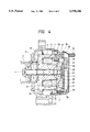
- FIG. 1 is an axial sectional view of a liquid cooled a.c. generator embodying the present invention.
- FIG. 2 is a partial cutaway elevational view of FIG. 1.
- FIG. 3 is an axial sectional view of another liquid cooled a.c. generator embodying the present invention.
- FIG. 4 is an axial sectional view of a conventional liquid cooled a.c. generator.
- FIG. 5 is a partial cutaway elevational view of FIG. 4.
- FIG. 1 is an axial sectional view of a liquid cooled a.c. generator and FIG. 2 is a partial cutaway elevational view of FIG. 1, wherein same reference characters designate corresponding component parts of the aforementioned conventional liquid cooled a.c. generator and the description of them will be omitted.
- numeral 25 denotes a tube trough to be closed with a bracket cover 17 provided in a rear bracket 12.
- One end 25a of the tube trough is connected to an inlet pipe 14, whereas the other end 25b communicates with the internal space 27 of the rear bracket 12 via a through-hole 26.
- thermoconductive tube 28 denotes a through-hole for allowing the internal space 27 to communicate with an outlet pipe 15, and 29 a good thermoconductive tube forming the cooling-fluid passage, the thermoconductive tube being made of thermoconductive, flame- and heat-resistant silicone rubber.
- the tube 29 is passed through the through-hole 26 of the rear bracket 12 in such a state that the rear bracket 12 is free from the bracket cover 17 before being fitted to the body of a front bracket 8.
- the tube 29 projected inside the rear bracket 12 is wound twice in the internal space 27 and then the rear end 29a of the tube 29 is fitted into the outlet pipe 15 via the through-hole 28.
- the tube 29 projected outside the rear bracket 12 is forced through the tube trough 25 and the rear end 29b of the tube 29 is fitted into the inlet pipe 14.
- the bracket cover 17 is secured thereto so as to contain the tube 29 in the tube trough 25 and the internal space 27.
- the low-temperature cooling fluid introduced from the inlet pipe 14 starts cooling the rectifier 19, the voltage regulator 21 and the bearing 13 which are giving off low-temperature heat and then flows into the stator coil 7 having high-temperature heat before flowing out of the outlet pipe 15. Therefore, the cooling operation can be performed with efficiency. Moreover, a greater cooling effect is achievable as the stator coil 7 that has conventionally been cooled indirectly can be cooled directly by the tube 29.
- thermoconductive filler 30 If the opening formed on the outer periphery of the tube 29 housed in the tube trough 25 and the internal space 27 as shown in FIG. 3 according to the first aspect of the present invention is filled with a thermoconductive filler 30, not only the pressure resistance but also the thermoconductivity of the tube 29 improves, thus increasing the cooling efficiency further.
- the front side is to be air-cooled by the fan 11 according to the first and second aspects of the present invention
- the front side like the rear side may be water-cooled by the tube in order to water-cool the whole structure.
- the cooling-fluid passage formed with one tube according to the present invention has the effect of making such a liquid cooled a.c. generator less costly and also improving its watertight reliability and cooling efficiency.
Abstract
A liquid cooled a.c. generator whose cooling-fluid passage is formed with a thermoconductive tube in order to offer not only excellent watertight reliability but also greater cooling efficiency. In other words, a cooling-fluid passage for use in cooling any part to be liquid-cooled is formed with a good thermoconductive tube.
Description
This is a Continuation of application Ser. No. 08/635,783 filed on Apr. 22, 1996, now abandoned which is a Continuation of application Ser. No. 08/225,312 filed Apr. 8, 1994 now abandoned.
1. Field of the Invention
The present invention relates to a liquid-cooled a.c. generator for use in a vehicle.
2. Description of the Prior Art
FIG. 4 is an axial sectional view of a conventional liquid cooled a.c. generator as disclosed in Unexamined Japanese Patent Publication Sho-62-178137/(1987) and FIG. 5 is a partial cutaway elevational view of FIG. 4. In FIG. 4, numeral 1 denotes a rotary shaft to which a pulley 2 is secured; 3, a rotor having a pole core, which is secured to the rotary shaft 1; 5, an excitation coil held on the pole core 4 on the fixed side; 6, a stator core which holds a stator coil 7; and 8, a front bracket for supporting the stator core 6, the front bracket having a cooling-air intake vent 9 and an exhaust vent 10. Further, numeral 11 denotes a fan fitted to the rotor 3; 12, a cast rear bracket for holding a bearing 13, the rear bracket being provided with cooling-fluid inlet and outlet pipes 14 and 15; 16, a recessed cooling-fluid passage in the rear bracket 12; 17, a bracket cover made of an aluminum-plate fitted to the rear bracket 12 and used for watertightly holding the cooling-fluid passage 16 by means of seals 18; 19, a rectifier secured via a heat sink 20 to the bracket cover 17; 21, a voltage regulator secured via a heat sink 22 to the bracket cover 17; 23, a protective cover; and 24 a thermoconductive filler filled between the rear bracket 12 and the stator coil 7.
The cooling action will subsequently be described. The rotary shaft 1 is rotated by a vehicular engine via the belt and the pulley 2. The cooling air is taken in by the fan 11 from the intake vent 9 and made to flow through the front bracket 8 so as to cool the front sides of the bearing 13 and the stator coil 7. The cooling air is then discharged from the exhaust vent 10.
On the other hand, part of a low-temperature cooling fluid in the engine is caused to branch off and introduced from the inlet pipe 14 into the cooling-fluid passage 16. The cooling fluid is then passed through the passage 16 as shown by an arrow in FIG. 5 and caused to flow out of the outlet pipe 15. At this time, the heat of the rectifier 19 and the voltage regulator 21 is transmitted from the respective heat sinks 20 and 22 to the bracket cover 17, whereas the heat of the bearing 13 is transmitted to the rear bracket 12, whereas the heat on the rear side of the stator coil 7 is transmitted from the thermoconductive filler 24 to the rear bracket 12, so that the heat of these component parts is reduced by the cooling fluid being circulated therein.
As set forth above, the cooling fluid circulated in the cooling-fluid passage 16 closed with the bracket cover 17 is used to discharge the heat of the rectifier 19, the voltage regulator 21, the bearing 13 and the stator coil 7 outside in the conventional a.c. generator. Notwithstanding, the necessity of disposing the seals 18 at various places along the cooling-fluid passage 16 results in increasing not only the number of parts but also production cost. As the reliability of their watertightness is greatly affected by the presence of a cavity in the rear bracket 12 and the adherence of the seals 18, there may arise a water leakage problem. Another problem is that the indirect cooling of the stator coil 7 via the rear bracket 12 tends to lower cooling efficiency.
In view of the foregoing problems to be solved, an object of the present invention is to provide a liquid cooled a.c. generator excellent in watertight reliability attained by forming a cooling-fluid passage with a tube and what is inexpensive and also capable of improving cooling efficiency.
A liquid cooled a.c. generator according to the present invention is so constructed that a cooling-fluid passage is formed with a good thermoconductive tube.
The tube is forced through a tube trough and in the internal space of a bracket and is housed therein.
A thermoconductive filler is used for fixing the tube in the tube trough and the internal space.
Since the cooling-fluid passage is formed with a good thermoconductive tube, watertightness is improvable without the provision of seals and cooling efficiency is also increased.
FIG. 1 is an axial sectional view of a liquid cooled a.c. generator embodying the present invention.
FIG. 2 is a partial cutaway elevational view of FIG. 1.
FIG. 3 is an axial sectional view of another liquid cooled a.c. generator embodying the present invention.
FIG. 4 is an axial sectional view of a conventional liquid cooled a.c. generator.
FIG. 5 is a partial cutaway elevational view of FIG. 4.
Referring to FIGS. 1 and 2, an embodiment of the present invention will be described. FIG. 1 is an axial sectional view of a liquid cooled a.c. generator and FIG. 2 is a partial cutaway elevational view of FIG. 1, wherein same reference characters designate corresponding component parts of the aforementioned conventional liquid cooled a.c. generator and the description of them will be omitted. In FIGS. 1 and 2, numeral 25 denotes a tube trough to be closed with a bracket cover 17 provided in a rear bracket 12. One end 25a of the tube trough is connected to an inlet pipe 14, whereas the other end 25b communicates with the internal space 27 of the rear bracket 12 via a through-hole 26. Further, numeral 28 denotes a through-hole for allowing the internal space 27 to communicate with an outlet pipe 15, and 29 a good thermoconductive tube forming the cooling-fluid passage, the thermoconductive tube being made of thermoconductive, flame- and heat-resistant silicone rubber.
First, the tube 29 is passed through the through-hole 26 of the rear bracket 12 in such a state that the rear bracket 12 is free from the bracket cover 17 before being fitted to the body of a front bracket 8. The tube 29 projected inside the rear bracket 12 is wound twice in the internal space 27 and then the rear end 29a of the tube 29 is fitted into the outlet pipe 15 via the through-hole 28. Then the tube 29 projected outside the rear bracket 12 is forced through the tube trough 25 and the rear end 29b of the tube 29 is fitted into the inlet pipe 14. After the rear bracket 12 is fixed to the body, the bracket cover 17 is secured thereto so as to contain the tube 29 in the tube trough 25 and the internal space 27. When the pressure of the cooling fluid is applied to the tube 29 in this state, it will be inflated and settled in position as shown in FIGS. 1 and 2.
Seals can thus be dispensed with since the cooling-fluid passage is formed with one tube 29 and the watertightness is improved. The low-temperature cooling fluid introduced from the inlet pipe 14 starts cooling the rectifier 19, the voltage regulator 21 and the bearing 13 which are giving off low-temperature heat and then flows into the stator coil 7 having high-temperature heat before flowing out of the outlet pipe 15. Therefore, the cooling operation can be performed with efficiency. Moreover, a greater cooling effect is achievable as the stator coil 7 that has conventionally been cooled indirectly can be cooled directly by the tube 29.
If the opening formed on the outer periphery of the tube 29 housed in the tube trough 25 and the internal space 27 as shown in FIG. 3 according to the first aspect of the present invention is filled with a thermoconductive filler 30, not only the pressure resistance but also the thermoconductivity of the tube 29 improves, thus increasing the cooling efficiency further.
Although the front side is to be air-cooled by the fan 11 according to the first and second aspects of the present invention, the front side like the rear side may be water-cooled by the tube in order to water-cool the whole structure.
As set forth above, the cooling-fluid passage formed with one tube according to the present invention has the effect of making such a liquid cooled a.c. generator less costly and also improving its watertight reliability and cooling efficiency.
Claims (3)
1. A fluid-cooled a.c. generator for use in a vehicle, comprising:
a rotary shaft driven by an engine of the vehicle;
a rotor core fixed to said rotary shaft and adapted to be excited by an excitation coil;
a stator core surrounding said rotor disposed opposite an outer periphery of said rotor core and mounting a stator coil wound on said stator core:
a one piece thermoconductive fluid tube located within said generator and defining a cooling-fluid passage; and
a bracket member on which a tube trough is formed, and a bracket cover to close said tube trough;
wherein said one piece thermoconductive fluid tube is placed within said tube trough and in an internal space of said bracket member so as to house the tube therein.
2. A fluid cooled a.c. generator as claimed in claim 1, wherein a thermoconductive filler is used for fill-fixing the one piece tube in the tube trough and the internal space.
3. A fluid cooled a.c. generator as claimed in claim 1, wherein said flexible one piece thermoconductive fluid tube is made of silicon rubber.
Priority Applications (1)
| Application Number | Priority Date | Filing Date | Title |
|---|---|---|---|
| US08/848,699 US5798586A (en) | 1993-04-09 | 1997-04-29 | Liquid cooled A.C. generator for use in vehicle |
Applications Claiming Priority (5)
| Application Number | Priority Date | Filing Date | Title |
|---|---|---|---|
| JP5083270A JP2842500B2 (en) | 1993-04-09 | 1993-04-09 | Vehicle generator |
| JP5-083270 | 1993-04-09 | ||
| US22531294A | 1994-04-08 | 1994-04-08 | |
| US63578396A | 1996-04-22 | 1996-04-22 | |
| US08/848,699 US5798586A (en) | 1993-04-09 | 1997-04-29 | Liquid cooled A.C. generator for use in vehicle |
Related Parent Applications (1)
| Application Number | Title | Priority Date | Filing Date |
|---|---|---|---|
| US63578396A Continuation | 1993-04-09 | 1996-04-22 |
Publications (1)
| Publication Number | Publication Date |
|---|---|
| US5798586A true US5798586A (en) | 1998-08-25 |
Family
ID=13797671
Family Applications (1)
| Application Number | Title | Priority Date | Filing Date |
|---|---|---|---|
| US08/848,699 Expired - Lifetime US5798586A (en) | 1993-04-09 | 1997-04-29 | Liquid cooled A.C. generator for use in vehicle |
Country Status (2)
| Country | Link |
|---|---|
| US (1) | US5798586A (en) |
| JP (1) | JP2842500B2 (en) |
Cited By (32)
| Publication number | Priority date | Publication date | Assignee | Title |
|---|---|---|---|---|
| US5929543A (en) * | 1996-09-16 | 1999-07-27 | Isad Electronic Systems Gmbh & Co. Kg | Electric machine having a cooling jacket |
| US6072253A (en) * | 1998-12-07 | 2000-06-06 | Ford Motor Company | Liquid-cooled electrical machine |
| US6160332A (en) * | 1999-01-13 | 2000-12-12 | Mitsubishi Denki Kabushiki Kaisha | Liquid cooled brushless generator for vehicles |
| US6169344B1 (en) * | 1999-02-23 | 2001-01-02 | Mitsubishi Denki Kabushiki Kaisha | Alternating current generator for vehicle |
| EP1199787A1 (en) * | 2000-10-17 | 2002-04-24 | Mitsubishi Denki Kabushiki Kaisha | Automotive alternator with cooling of the stator coil ends |
| US6414407B1 (en) * | 2000-08-09 | 2002-07-02 | Visteon Global Technologies, Inc. | Liquid-cooled electrical machine with integral bypass |
| US6441518B1 (en) * | 2000-09-19 | 2002-08-27 | Visteon Global Technologies, Inc. | Liquid-cooled electrical machine with parallel flow |
| US20020153784A1 (en) * | 2000-02-11 | 2002-10-24 | Uwe Kanppenberger | Housing and production method for an end winding |
| US6538352B2 (en) * | 2000-11-08 | 2003-03-25 | Mitsubishi Denki Kabushiki Kaisha | Automotive alternator having a rectifier heat sink and voltage regulator heat sink integrated in one single support structure |
| US20030127920A1 (en) * | 2002-01-08 | 2003-07-10 | Hitachi Ltd. | Alternator for vehicle |
| US20040000820A1 (en) * | 2002-06-13 | 2004-01-01 | Cromas Joseph Charles | Automotive generator |
| US20050023909A1 (en) * | 2002-06-13 | 2005-02-03 | Cromas Joseph Charles | Automotive generator |
| EP1676023A2 (en) * | 2003-10-06 | 2006-07-05 | Edward Woods | Power generation systems and methods of generating power |
| US20070145836A1 (en) * | 2005-12-22 | 2007-06-28 | Emerson Electric Co. | Winding lead cooling for motor with heat-sensitive electronic components |
| US20070170821A1 (en) * | 2006-01-20 | 2007-07-26 | Denso Corporation | Brushless automotive alternator having improved structure for minimizing temperature of auxiliary rectifying elements |
| US20070188028A1 (en) * | 2004-03-18 | 2007-08-16 | Telma | Cooling conduit for a rotary electric machine and a rotary electric machine comprising said conduit |
| US7314034B1 (en) | 2007-01-23 | 2008-01-01 | Delphi Technologies, Inc. | System for verifying cylinder deactivation status in a multi-cylinder engine |
| US20080185925A1 (en) * | 2007-02-05 | 2008-08-07 | Kurple Alexander C | System and method to control temperature of an alternator and/or an engine in a vehicle |
| US20090278413A1 (en) * | 2003-05-27 | 2009-11-12 | Pratt & Whitney Canada Corp. | Architecture for electric machine |
| US20100085706A1 (en) * | 2008-10-07 | 2010-04-08 | Caterpillar Inc. | Helical conduit enabled for casting inside a housing |
| US20100102647A1 (en) * | 2008-10-28 | 2010-04-29 | Caterpillar Inc | Electric motor/generator low hydraulic resistance cooling mechanism |
| US20120062056A1 (en) * | 2010-09-10 | 2012-03-15 | Remy Technologies, L.L.C. | Electric machine including a stator having a stator sleeve and method of cooling a stator |
| US20120217829A1 (en) * | 2009-09-17 | 2012-08-30 | Robert Bosch Gmbh | Electric machine |
| WO2013013691A1 (en) * | 2011-07-22 | 2013-01-31 | Baumüller Nürnberg GmbH | Machine housing with a cooling system |
| US20130119794A1 (en) * | 2011-11-10 | 2013-05-16 | Kabushiki Kaisha Yaskawa Denki | Rotating electrical machine |
| US20140265670A1 (en) * | 2013-03-14 | 2014-09-18 | Remy Technologies, Llc | L-shaped sheet metal cooling jacket with baffles and integrated power electronics |
| US9559569B2 (en) | 2012-02-13 | 2017-01-31 | Ge Aviation Systems Llc | Arrangement for cooling an electric machine with a layer of thermally conducting and electrically insulating material |
| DE102015215667A1 (en) * | 2015-08-18 | 2017-02-23 | Continental Automotive Gmbh | Liquid cooling of an electric machine |
| EP3367544A1 (en) * | 2017-02-22 | 2018-08-29 | Siemens Aktiengesellschaft | Dynamo-electric machine having a cooling element |
| US20210067023A1 (en) * | 2019-08-30 | 2021-03-04 | Apple Inc. | Haptic actuator including shaft coupled field member and related methods |
| US11228229B2 (en) | 2016-11-08 | 2022-01-18 | Aros Electronics Ab | Electric machine with liquid cooling |
| WO2023072538A1 (en) * | 2021-10-28 | 2023-05-04 | Mahle International Gmbh | Electrically excited synchronous machine |
Families Citing this family (3)
| Publication number | Priority date | Publication date | Assignee | Title |
|---|---|---|---|---|
| JP3612807B2 (en) * | 1995-07-28 | 2005-01-19 | 株式会社デンソー | Rotating electrical machine for water pump integrated vehicle |
| JP3770200B2 (en) * | 2002-04-26 | 2006-04-26 | 株式会社日立製作所 | AC generator for vehicles |
| JP7113945B1 (en) * | 2021-05-17 | 2022-08-05 | 三菱電機株式会社 | Rotating electric machine |
Citations (7)
| Publication number | Priority date | Publication date | Assignee | Title |
|---|---|---|---|---|
| US3624432A (en) * | 1969-12-19 | 1971-11-30 | Bbc Brown Boveri & Cie | Arrangement for securing electrical conductor bars within slots to prevent vibration |
| US3681628A (en) * | 1970-09-14 | 1972-08-01 | Christoslaw Krastchew | Cooling arrangement for a dynamoelectric machine |
| JPS62178137A (en) * | 1986-01-30 | 1987-08-05 | Mitsubishi Electric Corp | Ac generator for car |
| US4739204A (en) * | 1986-01-30 | 1988-04-19 | Mitsubishi Denki Kabushiki Kaisha | Liquid cooled a.c. vehicle generator |
| US4870307A (en) * | 1987-04-13 | 1989-09-26 | Mitsubishi Denki Kabushiki Kaisha | Block-mounted water cooled ac generator |
| US4980588A (en) * | 1986-02-14 | 1990-12-25 | Mitsubishi Denki Kabushiki Kaisha | Water-cooled vehicle generator |
| US5095235A (en) * | 1989-12-04 | 1992-03-10 | Mitsubishi Denki K.K. | Vehicle ac generator |
Family Cites Families (3)
| Publication number | Priority date | Publication date | Assignee | Title |
|---|---|---|---|---|
| JP2622127B2 (en) * | 1987-10-19 | 1997-06-18 | 三菱電機株式会社 | AC generator for vehicles |
| JPH01101152U (en) * | 1987-12-22 | 1989-07-07 | ||
| JPH03100987A (en) * | 1989-09-12 | 1991-04-25 | Nec Corp | Magnetic disk device |
-
1993
- 1993-04-09 JP JP5083270A patent/JP2842500B2/en not_active Expired - Lifetime
-
1997
- 1997-04-29 US US08/848,699 patent/US5798586A/en not_active Expired - Lifetime
Patent Citations (7)
| Publication number | Priority date | Publication date | Assignee | Title |
|---|---|---|---|---|
| US3624432A (en) * | 1969-12-19 | 1971-11-30 | Bbc Brown Boveri & Cie | Arrangement for securing electrical conductor bars within slots to prevent vibration |
| US3681628A (en) * | 1970-09-14 | 1972-08-01 | Christoslaw Krastchew | Cooling arrangement for a dynamoelectric machine |
| JPS62178137A (en) * | 1986-01-30 | 1987-08-05 | Mitsubishi Electric Corp | Ac generator for car |
| US4739204A (en) * | 1986-01-30 | 1988-04-19 | Mitsubishi Denki Kabushiki Kaisha | Liquid cooled a.c. vehicle generator |
| US4980588A (en) * | 1986-02-14 | 1990-12-25 | Mitsubishi Denki Kabushiki Kaisha | Water-cooled vehicle generator |
| US4870307A (en) * | 1987-04-13 | 1989-09-26 | Mitsubishi Denki Kabushiki Kaisha | Block-mounted water cooled ac generator |
| US5095235A (en) * | 1989-12-04 | 1992-03-10 | Mitsubishi Denki K.K. | Vehicle ac generator |
Cited By (49)
| Publication number | Priority date | Publication date | Assignee | Title |
|---|---|---|---|---|
| US5929543A (en) * | 1996-09-16 | 1999-07-27 | Isad Electronic Systems Gmbh & Co. Kg | Electric machine having a cooling jacket |
| GB2346487B (en) * | 1998-12-07 | 2003-12-10 | Ford Motor Co | Liquid-cooled electrical machine |
| US6072253A (en) * | 1998-12-07 | 2000-06-06 | Ford Motor Company | Liquid-cooled electrical machine |
| GB2346487A (en) * | 1998-12-07 | 2000-08-09 | Ford Motor Co | Liquid-cooled electrical machine |
| US6160332A (en) * | 1999-01-13 | 2000-12-12 | Mitsubishi Denki Kabushiki Kaisha | Liquid cooled brushless generator for vehicles |
| US6169344B1 (en) * | 1999-02-23 | 2001-01-02 | Mitsubishi Denki Kabushiki Kaisha | Alternating current generator for vehicle |
| US20020153784A1 (en) * | 2000-02-11 | 2002-10-24 | Uwe Kanppenberger | Housing and production method for an end winding |
| US6414407B1 (en) * | 2000-08-09 | 2002-07-02 | Visteon Global Technologies, Inc. | Liquid-cooled electrical machine with integral bypass |
| US6441518B1 (en) * | 2000-09-19 | 2002-08-27 | Visteon Global Technologies, Inc. | Liquid-cooled electrical machine with parallel flow |
| US6657331B2 (en) * | 2000-10-17 | 2003-12-02 | Mitsubishi Denki Kabushiki Kaisha | Automotive alternator |
| EP1199787A1 (en) * | 2000-10-17 | 2002-04-24 | Mitsubishi Denki Kabushiki Kaisha | Automotive alternator with cooling of the stator coil ends |
| US6538352B2 (en) * | 2000-11-08 | 2003-03-25 | Mitsubishi Denki Kabushiki Kaisha | Automotive alternator having a rectifier heat sink and voltage regulator heat sink integrated in one single support structure |
| US20030127920A1 (en) * | 2002-01-08 | 2003-07-10 | Hitachi Ltd. | Alternator for vehicle |
| US6864603B2 (en) * | 2002-01-08 | 2005-03-08 | Hitachi, Ltd. | Alternator for vehicle |
| US20040000820A1 (en) * | 2002-06-13 | 2004-01-01 | Cromas Joseph Charles | Automotive generator |
| US20050023909A1 (en) * | 2002-06-13 | 2005-02-03 | Cromas Joseph Charles | Automotive generator |
| US20090278413A1 (en) * | 2003-05-27 | 2009-11-12 | Pratt & Whitney Canada Corp. | Architecture for electric machine |
| US7709980B2 (en) * | 2003-05-27 | 2010-05-04 | Pratt & Whitney Canada Corp. | Architecture for electric machine |
| US9502943B2 (en) | 2003-10-06 | 2016-11-22 | Powersys, Llc | Power generation systems and methods of generating power |
| US8222756B2 (en) | 2003-10-06 | 2012-07-17 | Powersys, Llc | Power generation systems |
| US8492913B2 (en) | 2003-10-06 | 2013-07-23 | Powersys, Llc | Power generation systems |
| US8829698B2 (en) | 2003-10-06 | 2014-09-09 | Powersys, Llc | Power generation systems |
| EP1676023A2 (en) * | 2003-10-06 | 2006-07-05 | Edward Woods | Power generation systems and methods of generating power |
| EP1676023B1 (en) * | 2003-10-06 | 2018-04-04 | PowerSys, LLC | Power generation systems and methods of generating power |
| US20070188028A1 (en) * | 2004-03-18 | 2007-08-16 | Telma | Cooling conduit for a rotary electric machine and a rotary electric machine comprising said conduit |
| US20070145836A1 (en) * | 2005-12-22 | 2007-06-28 | Emerson Electric Co. | Winding lead cooling for motor with heat-sensitive electronic components |
| US20070170821A1 (en) * | 2006-01-20 | 2007-07-26 | Denso Corporation | Brushless automotive alternator having improved structure for minimizing temperature of auxiliary rectifying elements |
| US7449806B2 (en) * | 2006-01-20 | 2008-11-11 | Denso Corporation | Brushless automotive alternator having improved structure for minimizing temperature of auxiliary rectifying elements |
| US7314034B1 (en) | 2007-01-23 | 2008-01-01 | Delphi Technologies, Inc. | System for verifying cylinder deactivation status in a multi-cylinder engine |
| US7509929B2 (en) | 2007-02-05 | 2009-03-31 | Ford Global Technologies, Llc | System and method to control temperature of an alternator and/or an engine in a vehicle |
| US20080185925A1 (en) * | 2007-02-05 | 2008-08-07 | Kurple Alexander C | System and method to control temperature of an alternator and/or an engine in a vehicle |
| US20100085706A1 (en) * | 2008-10-07 | 2010-04-08 | Caterpillar Inc. | Helical conduit enabled for casting inside a housing |
| US7965002B2 (en) | 2008-10-07 | 2011-06-21 | Caterpillar Inc. | Helical conduit enabled for casting inside a housing |
| US8067865B2 (en) | 2008-10-28 | 2011-11-29 | Caterpillar Inc. | Electric motor/generator low hydraulic resistance cooling mechanism |
| US20100102647A1 (en) * | 2008-10-28 | 2010-04-29 | Caterpillar Inc | Electric motor/generator low hydraulic resistance cooling mechanism |
| US9184643B2 (en) * | 2009-09-17 | 2015-11-10 | Robert Bosch Gmbh | Electric machine |
| US20120217829A1 (en) * | 2009-09-17 | 2012-08-30 | Robert Bosch Gmbh | Electric machine |
| US20120062056A1 (en) * | 2010-09-10 | 2012-03-15 | Remy Technologies, L.L.C. | Electric machine including a stator having a stator sleeve and method of cooling a stator |
| US8378550B2 (en) * | 2010-09-10 | 2013-02-19 | Remy Technologies, L.L.C. | Electric machine including a stator having a stator sleeve and method of cooling a stator |
| WO2013013691A1 (en) * | 2011-07-22 | 2013-01-31 | Baumüller Nürnberg GmbH | Machine housing with a cooling system |
| US20130119794A1 (en) * | 2011-11-10 | 2013-05-16 | Kabushiki Kaisha Yaskawa Denki | Rotating electrical machine |
| US9559569B2 (en) | 2012-02-13 | 2017-01-31 | Ge Aviation Systems Llc | Arrangement for cooling an electric machine with a layer of thermally conducting and electrically insulating material |
| US20140265670A1 (en) * | 2013-03-14 | 2014-09-18 | Remy Technologies, Llc | L-shaped sheet metal cooling jacket with baffles and integrated power electronics |
| US9450468B2 (en) * | 2013-03-14 | 2016-09-20 | Remy Technologies, Llc | L-shaped sheet metal cooling jacket with baffles and integrated power electronics |
| DE102015215667A1 (en) * | 2015-08-18 | 2017-02-23 | Continental Automotive Gmbh | Liquid cooling of an electric machine |
| US11228229B2 (en) | 2016-11-08 | 2022-01-18 | Aros Electronics Ab | Electric machine with liquid cooling |
| EP3367544A1 (en) * | 2017-02-22 | 2018-08-29 | Siemens Aktiengesellschaft | Dynamo-electric machine having a cooling element |
| US20210067023A1 (en) * | 2019-08-30 | 2021-03-04 | Apple Inc. | Haptic actuator including shaft coupled field member and related methods |
| WO2023072538A1 (en) * | 2021-10-28 | 2023-05-04 | Mahle International Gmbh | Electrically excited synchronous machine |
Also Published As
| Publication number | Publication date |
|---|---|
| JP2842500B2 (en) | 1999-01-06 |
| JPH06296348A (en) | 1994-10-21 |
Similar Documents
| Publication | Publication Date | Title |
|---|---|---|
| US5798586A (en) | Liquid cooled A.C. generator for use in vehicle | |
| KR900002802B1 (en) | Ac generator | |
| US4739204A (en) | Liquid cooled a.c. vehicle generator | |
| KR920000498B1 (en) | Rotary machine | |
| KR910002993B1 (en) | Ac generator for rolling stock | |
| JP3877898B2 (en) | AC generator for vehicles | |
| JPH07194060A (en) | Alternator for vehicle | |
| JP2006237591A (en) | Liquid cooling heat dissipation module | |
| JP4184871B2 (en) | Liquid-cooled rotary electric machine | |
| JPS5983557A (en) | Cooling structure in generator for vehicle | |
| JPS62178139A (en) | Cooler for generator for car | |
| JPH0596959A (en) | Electric running vehicle | |
| JPS62178137A (en) | Ac generator for car | |
| JPH08205461A (en) | Inverter driven electric rotating machine | |
| RU98114495A (en) | PUMP UNIT | |
| KR200318453Y1 (en) | Water cooling frame of motor for electric vehicle | |
| JPS62225146A (en) | Ac generator for vehicle | |
| JP2921221B2 (en) | Outboard motor electrical component cooling structure | |
| JPS62236338A (en) | Ac generator for vehicle | |
| JPS62244242A (en) | Ac generator for vehicle | |
| JPH0467429B2 (en) | ||
| JPH0433540A (en) | Cooling structure of motor | |
| JPS62178138A (en) | Ac generator for car | |
| JPS62213530A (en) | Ac generator for vehicle | |
| JP4092483B2 (en) | Cooling structure of rotating electric machine |
Legal Events
| Date | Code | Title | Description |
|---|---|---|---|
| STCF | Information on status: patent grant |
Free format text: PATENTED CASE |
|
| FEPP | Fee payment procedure |
Free format text: PAYOR NUMBER ASSIGNED (ORIGINAL EVENT CODE: ASPN); ENTITY STATUS OF PATENT OWNER: LARGE ENTITY |
|
| FPAY | Fee payment |
Year of fee payment: 4 |
|
| FPAY | Fee payment |
Year of fee payment: 8 |
|
| FPAY | Fee payment |
Year of fee payment: 12 |