US5796683A - Magneto-optical recording device having a controllable polarizing filter - Google Patents
Magneto-optical recording device having a controllable polarizing filter Download PDFInfo
- Publication number
- US5796683A US5796683A US08/823,757 US82375797A US5796683A US 5796683 A US5796683 A US 5796683A US 82375797 A US82375797 A US 82375797A US 5796683 A US5796683 A US 5796683A
- Authority
- US
- United States
- Prior art keywords
- laser beam
- polarization
- recording
- optical
- reproduction
- Prior art date
- Legal status (The legal status is an assumption and is not a legal conclusion. Google has not performed a legal analysis and makes no representation as to the accuracy of the status listed.)
- Expired - Lifetime
Links
- 230000010287 polarization Effects 0.000 claims abstract description 137
- 230000003287 optical effect Effects 0.000 claims abstract description 73
- 230000000903 blocking effect Effects 0.000 claims description 64
- 239000010408 film Substances 0.000 claims description 40
- 230000005291 magnetic effect Effects 0.000 claims description 33
- 239000004973 liquid crystal related substance Substances 0.000 claims description 27
- 239000011521 glass Substances 0.000 claims description 24
- 239000000463 material Substances 0.000 claims description 9
- BQCADISMDOOEFD-UHFFFAOYSA-N Silver Chemical group [Ag] BQCADISMDOOEFD-UHFFFAOYSA-N 0.000 claims description 7
- 229910052751 metal Inorganic materials 0.000 claims description 2
- 239000002184 metal Substances 0.000 claims description 2
- 239000010409 thin film Substances 0.000 claims description 2
- 238000000034 method Methods 0.000 abstract description 30
- 230000005855 radiation Effects 0.000 abstract description 4
- 238000010586 diagram Methods 0.000 description 10
- 238000002834 transmittance Methods 0.000 description 10
- 239000000758 substrate Substances 0.000 description 8
- 230000008901 benefit Effects 0.000 description 7
- 229910052709 silver Inorganic materials 0.000 description 6
- 239000004332 silver Substances 0.000 description 6
- 230000005415 magnetization Effects 0.000 description 5
- 230000004907 flux Effects 0.000 description 4
- 239000004065 semiconductor Substances 0.000 description 4
- 230000000694 effects Effects 0.000 description 3
- 230000002093 peripheral effect Effects 0.000 description 3
- 239000004417 polycarbonate Substances 0.000 description 2
- 229920000515 polycarbonate Polymers 0.000 description 2
- 239000011347 resin Substances 0.000 description 2
- 229920005989 resin Polymers 0.000 description 2
- 230000000630 rising effect Effects 0.000 description 2
- 239000013589 supplement Substances 0.000 description 2
- 230000003321 amplification Effects 0.000 description 1
- 239000000919 ceramic Substances 0.000 description 1
- 238000013144 data compression Methods 0.000 description 1
- 230000006837 decompression Effects 0.000 description 1
- 239000005262 ferroelectric liquid crystals (FLCs) Substances 0.000 description 1
- 230000006870 function Effects 0.000 description 1
- RBTKNAXYKSUFRK-UHFFFAOYSA-N heliogen blue Chemical compound [Cu].[N-]1C2=C(C=CC=C3)C3=C1N=C([N-]1)C3=CC=CC=C3C1=NC([N-]1)=C(C=CC=C3)C3=C1N=C([N-]1)C3=CC=CC=C3C1=N2 RBTKNAXYKSUFRK-UHFFFAOYSA-N 0.000 description 1
- 238000001755 magnetron sputter deposition Methods 0.000 description 1
- 230000007246 mechanism Effects 0.000 description 1
- 239000007769 metal material Substances 0.000 description 1
- 238000003199 nucleic acid amplification method Methods 0.000 description 1
- 229920003229 poly(methyl methacrylate) Polymers 0.000 description 1
- 239000004926 polymethyl methacrylate Substances 0.000 description 1
- 230000009467 reduction Effects 0.000 description 1
- 238000009877 rendering Methods 0.000 description 1
- 229940100890 silver compound Drugs 0.000 description 1
- 150000003379 silver compounds Chemical class 0.000 description 1
- 230000005236 sound signal Effects 0.000 description 1
- 238000011144 upstream manufacturing Methods 0.000 description 1
Images


Classifications
-
- G—PHYSICS
- G11—INFORMATION STORAGE
- G11B—INFORMATION STORAGE BASED ON RELATIVE MOVEMENT BETWEEN RECORD CARRIER AND TRANSDUCER
- G11B7/00—Recording or reproducing by optical means, e.g. recording using a thermal beam of optical radiation by modifying optical properties or the physical structure, reproducing using an optical beam at lower power by sensing optical properties; Record carriers therefor
- G11B7/12—Heads, e.g. forming of the optical beam spot or modulation of the optical beam
- G11B7/135—Means for guiding the beam from the source to the record carrier or from the record carrier to the detector
- G11B7/1365—Separate or integrated refractive elements, e.g. wave plates
-
- G—PHYSICS
- G11—INFORMATION STORAGE
- G11B—INFORMATION STORAGE BASED ON RELATIVE MOVEMENT BETWEEN RECORD CARRIER AND TRANSDUCER
- G11B11/00—Recording on or reproducing from the same record carrier wherein for these two operations the methods are covered by different main groups of groups G11B3/00 - G11B7/00 or by different subgroups of group G11B9/00; Record carriers therefor
- G11B11/10—Recording on or reproducing from the same record carrier wherein for these two operations the methods are covered by different main groups of groups G11B3/00 - G11B7/00 or by different subgroups of group G11B9/00; Record carriers therefor using recording by magnetic means or other means for magnetisation or demagnetisation of a record carrier, e.g. light induced spin magnetisation; Demagnetisation by thermal or stress means in the presence or not of an orienting magnetic field
- G11B11/105—Recording on or reproducing from the same record carrier wherein for these two operations the methods are covered by different main groups of groups G11B3/00 - G11B7/00 or by different subgroups of group G11B9/00; Record carriers therefor using recording by magnetic means or other means for magnetisation or demagnetisation of a record carrier, e.g. light induced spin magnetisation; Demagnetisation by thermal or stress means in the presence or not of an orienting magnetic field using a beam of light or a magnetic field for recording by change of magnetisation and a beam of light for reproducing, i.e. magneto-optical, e.g. light-induced thermomagnetic recording, spin magnetisation recording, Kerr or Faraday effect reproducing
- G11B11/10532—Heads
- G11B11/10541—Heads for reproducing
- G11B11/10543—Heads for reproducing using optical beam of radiation
Definitions
- the present invention relates to recording and reproduction apparatuses for magneto-optical recording media, and more particularly, to an information recording and reproduction apparatus that can carry out recording and reproduction on and from a magnetically induced superresolution magneto-optical recording medium at high density using a single optical system.
- a magneto-optical recording medium is noteworthy of its rewritable ability, large storage capacity, and high reliability. It is already put into practical use as the memory and the like for computers. However, the recording and reproducing technique of information at higher density is required in accordance with increase in the amount of information to be recorded and reduction in the size of the recording and reproduction apparatus.
- the technique for recording and reproducing information at higher density is divided into the technique at the recording and reproduction apparatus end and the technique of the recording medium end.
- the former includes, in addition to the method of rendering the wavelength of a laser beam shorter, the so-called optical superresolution method.
- This method achieves a focused spot that exceeds the diffraction limit of a laser beam by inserting a light blocking object in the light path of the laser beam.
- This optical superresolution method is disclosed in "High Density Optical Recording by Superresolution", Japanese Journal of Applied Physics, Vol. 28, Supplement 28-3, pp. 197-200, 1989 by Y. Yamanaka et al., for example.
- the latter technique includes, in addition to the method of narrowing the pitch of the recording track of the medium, the method of improving the reproduction resolution using a magnetic multilayer film.
- This art of improving reproduction resolution using a magnetic multilayer film includes the step of providing a magneto-optical recording medium with a magnetic multilayer film having a recording layer and a reproduction layer.
- the entire light power of the laser beam is lowered since a light blocking object is inserted in the light path of the laser beam. Therefore, the temperature within the laser spot will not rise sufficiently up to the temperature (approximately 250° C.), that is required to carry out recording onto a recording layer, with a laser light source of the typical light power, resulting in difficulty in carrying out effective recording of information on a recording layer. As a result, there is a problem that data of a high transfer rate cannot be recorded effectively on a medium. If the entire light power is to be increased, on the other hand, a laser source of a light power that is greater than the conventional one will be required.
- the following advantage is obtained.
- the temperature within the laser spot (approximately 150° C.) required to read out information from a reproduction layer can easily be achieved with a laser beam of a typical light power while the substantial reproduction region can be made smaller than the diameter of the laser beam by applying the optical superresolution method to the laser beam for reproduction. As a result, the reproduction density can be improved.
- an optical system for recording and an optical system for reproduction must be provided separately in one information recording and reproduction apparatus that includes both the recording and reproduction function.
- the structure of the information recording and reproduction apparatus for a magneto-optical recording medium will become complicated. Therefore, there was a problem that the apparatus cannot be made compact.
- an object of the present invention is to provide an information recording and reproduction apparatus that is simplified in structure, and that allows information reproduction at high density from a magneto-optical recording medium.
- Another object of the present invention is to provide an information recording and reproduction apparatus for a magneto-optical recording medium that can commonly share one optical system for recording and reproduction.
- a further object of the present invention is to provide an information recording and reproduction apparatus that can reproduce information at high density from a magnetically induced superresolution magneto-optical recording medium.
- Still another object of the present invention is to provide an information recording and reproduction apparatus that can eliminate influence of a side lobe when using the optical superresolution method.
- an information recording and reproduction apparatus for a magneto-optical recording medium includes a magnetic head, an optical head, and an information reproduction circuit.
- the magnetic head responds to a recording signal indicating information to be recorded for applying a magnetic field to a signal recording plane of a magneto-optical recording medium.
- the optical head is commonly used both for recording and reproduction to emit a laser beam on the signal recording plane of the magneto-optical recording medium, and to detect a laser beam reflected from the signal recording plane.
- the information reproduction circuit reproduces information from the detected laser beam.
- the optical head includes a polarization control circuit that is adapted to block the inner portion of the laser beam emitted from the laser diode so that a laser beam formed of a main lobe and side lobes is emitted onto the signal recording plane only in a reproduction mode.
- an information recording and reproduction apparatus for a magneto-optical recording medium includes a magnetic head, an optical head, and an information reproduction circuit.
- the magnetic head responds to a recording signal indicating information to be recorded for applying a magnetic field to a signal recording plane of the magneto-optical recording medium.
- the optical head is commonly used both for recording and reproduction.
- the optical head emits a laser beam to the signal recording plane of the magneto-optical recording medium, and detects the laser beam reflected from the signal recording plane.
- the information reproduction circuit reproduces information from the reproduced laser beam.
- the optical head further includes a light source, a polarization plane rotary unit, a polarizing filter, an objective lens, and a polarization control circuit.
- the light source generates the laser beam.
- the polarization plane rotary unit transmits the generated laser beam while selectively rotating the direction of polarization of the laser beam.
- the polarizing filter receives the laser beam transmitted through the polarization plane rotary unit for transmitting the laser beam at its outer portion independent of the direction of polarization, and transmitting only the laser beam that is polarized in a particular direction at its inner portion.
- Tracking control is provided so that the objective lens is displaced with respect to the signal recording plane.
- the objective lens collects the laser beam transmitted through the polarizing filter onto the signal recording plane.
- the polarization control circuit controls the polarization plane rotary unit to rotate the direction of polarization of the laser beam emitted from the light source in a direction differing from the particular direction, so that an inner portion of the laser beam is blocked by the polarizing filter to have a laser beam formed of a main lobe and side lobes enter the objective lens in a reproduction mode.
- an information recording and reproduction apparatus for a magneto-optical recording medium includes a magnetic head, an optical head, and an information reproduction circuit.
- the magnetic head responds to a recording signal indicating information to be recorded by supplying a magnetic field to a signal recording plane of the magneto-optical recording medium.
- the optical head commonly used for both recording and reproduction emits a laser beam on the signal recording plane of the magneto-optical recording medium, and detects the laser beam reflected from the signal recording plane.
- the information reproduction circuit reproduces information from the detected laser beam.
- the optical head further includes an light source, a polarization plane rotary unit, a polarizing filter, an objective lens, and a polarization control circuit. The light source generates a laser beam.
- the polarization plane rotary unit transmits the generated laser beam while selectively rotating the direction of polarization of the laser beam in different directions between the outer portion and the inner portion.
- the polarizing filter receives the laser beam transmitted through the polarization plane rotary unit to transmit only the laser beam that is polarized in a particular direction. Tracking control is provided so that the objective lens is displaced with respect to the signal recording plane to collect the laser beam transmitted through the polarizing filter on the signal recording plane.
- the polarization control circuit controls the polarization plane rotary unit to rotate the direction of polarization of the laser beam generated from the light source in a particular direction at its outer portion, and in a direction different from the particular direction at its inner portion, so that an inner portion of the laser beam is blocked by the polarizing filter to have a laser beam formed of a main lobe and side lobes enter the objective lens in reproduction.
- the magneto-optical recording medium is a magnetically induced superresolution magneto-optical recording medium with a magnetic multilayer film structure including a recording layer and a reproduction layer.
- the polarization plane rotary unit rotates the direction of polarization of the laser beam electrically.
- the polarization plane rotary unit rotates the direction of polarization of the laser beam magnetically.
- the polarizing filter or the polarization plane rotary unit has a circular inner portion.
- the polarizing filter or the polarization plane rotary unit has a polygonal inner portion.
- the inner portion of the polarizing filter or the polarization plane rotary unit is offset from the center of the laser beam.
- the main advantage of the present invention is that the optical superresolution method can be implemented in only the laser beam for reproduction by controlling the direction of polarization of a laser beam in an information recording and reproduction apparatus with a single optical head.
- Another advantage of the present invention is that information reproduction at high density of a magnetically induced superresolution magneto-optical medium can be carried out by an information recording and reproduction apparatus of a simple structure using a single optical system.
- a further advantage of the present invention is that influence of a side lobe can be removed effectively even when the optical superresolution method is applied to the laser beam for reproduction.
- FIG. 1 is a sectional view of a stacked layer structure of a magnetically induced superresolution magneto-optical recording medium used in an embodiment of the present invention.
- FIG. 2 is a sectional view of another stacked layer structure of a magnetically induced superresolution magneto-optical recording medium used in an embodiment of the present invention.
- FIG. 3 is a sectional view of a further stacked layer structure of a magnetically induced superresolution magneto-optical recording medium used in an embodiment of the present invention.
- FIG. 4 is a block diagram showing an entire structure of an information recording and reproduction apparatus for a magneto-optical recording medium according to an embodiment of the present invention.
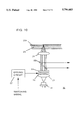
- FIG. 5 shows a structure of an optical head according to a first embodiment of the present invention.
- FIG. 6 is a side view of a structure of a polarization plane rotary unit of the optical head of FIG. 5.
- FIG. 7A is a side view showing a structure of a polarizing filter of the optical head of FIG. 5.
- FIG. 7B is a schematic diagram showing the characteristics of the polarizing filter of FIG. 7A.
- FIG. 8 is a diagram for describing a recording operation of the optical head of FIG. 5.
- FIGS. 9A-9C are diagrams for describing the relationship of magnetic field, pulse laser beam, and recording domain.
- FIG. 10 is a diagram for describing a reproduction operation of the optical head of FIG. 5.
- FIG. 11A is a side view showing a structure of a polarization plane rotary unit of an optical head according to a second embodiment of the present invention.
- FIG. 11B is a side view showing a structure of a polarizing filter of the optical head according to a second embodiment of the present invention.
- FIGS. 12A-12G schematically show various configurations of a light blocking body formed in a light path of a laser beam according to each embodiment of the present invention.
- FIGS. 13A and 13B are diagrams for describing an operation of a liquid crystal shutter as an alternative to the polarization plane rotary unit and polarizing filter of FIG. 5.
- FIGS. 14A and 14B are front views of a glass polarizer as an alternative to the polarizing filter shown in FIGS. 7A and 7B.
- FIG. 15 is a diagram for describing the operation principle of a Pockels cell as an alternative to the TN type liquid crystal shown in FIG. 6.
- FIG. 16 is a diagram for describing the operation principle of a Faraday cell as an alternative to the TN type liquid crystal shown in FIG. 6.
- FIG. 17 is a block diagram showing the case where a polarization beam splitter is used as an alternative to the polarizing filter in the second embodiment of the present invention.
- FIGS. 18-20 show the configuration of the bodies for blocking the inner portion of a laser beam in the optical head of FIG. 5.
- FIG. 21 is a graph showing the relationship between the intensity ratio (side lobe intensity / main lobe intensity; the same applies hereinafter) and the light blocking rate, and the relationship between the beam diameter of the main lobe and the light blocking rate when the circular light blocking body shown in FIG. 19 is used.
- FIG. 22 is a graph showing the relationship between the intensity ratio and the light blocking rate, and the relationship between the beam diameter of the main lobe and the light blocking rate when the rectangular light blocking body shown in FIG. 18 is used.
- FIGS. 23 and 24 show the state on the magneto-optical disk irradiated with the laser beam spot when the rectangular light blocking body of FIG. 18 and the circular light blocking body of FIG. 19, respectively, are used.
- FIG. 25 shows the state on the magneto-optical recording medium irradiated with the laser beam when a rectangular light blocking body is inserted perpendicular to the groove.
- FIG. 26 shows the state on the magneto-optical recording medium irradiated with a beam when a rectangular light blocking body is inserted perpendicular to the groove while being offset from the center of the laser beam.
- FIG. 27 shows the state on the magneto-optical recording medium irradiated with the beam when a circular light blocking body is inserted.
- FIGS. 28A and 28B show comparison in reproduction with and without a rectangular light blocking body.
- FIG. 29 shows the variation of the beam diameter of the main lobe and the intensity ratio of the side lobe with respect to the offset amount of the rectangular light blocking object.
- FIG. 30 schematically shows generation of a main lobe and side lobes due to the offset of the rectangular light blocking body from the center of the laser beam.
- FIG. 31 is a graph showing the relationship between crosstalk and recording power of the optical head shown in FIG. 5 for each light blocking rate.
- the magneto-optical recording medium employed in the present embodiment includes a magnetic multilayer film formed of a recording layer and a reproduction layer to allow high density recording as described above.
- This magneto-optical recording medium will be referred to as a magnetically induced superresolution magneto-optical recording medium hereinafter.
- the magnetically induced superresolution magneto-optical recording medium includes a substrate 1 formed of transmissive polycarbonate, glass, and the like, a first dielectric layer 2 formed of SiN on substrate 1, a reproduction layer 3 formed of GdFeCo on first dielectric layer 2, a recording layer 4 formed of TbFeCo on reproduction layer 3, a second dielectric layer 5 formed of SiN on recording layer 4, a heat radiating layer 6 formed of a metal having a high thermal conductivity such as A1 on second dielectric layer 5, and a protection layer 7 formed of ultraviolet curing resin on heat radiating layer 6.
- First and second dielectric layers 2 and 5 each have a film thickness of 800 ⁇ (tolerable error ⁇ 10 ⁇ ).
- Reproduction layer 3 has a film thickness of 1000 ⁇ (tolerable error ⁇ 10 ⁇ ).
- Recording layer 4 has a film thickness of 500 ⁇ (tolerable error ⁇ 10 ⁇ ).
- Heat radiating layer 6 has a film thickness of 200 ⁇ (tolerable error ⁇ 10 ⁇ ).
- Protection layer 7 has a film thickness of 10 ⁇ m (tolerable error ⁇ 1 ⁇ m).
- FIG. 2 Another example of a stacked layer structure of a magnetically induced superresolution magneto-optical recording medium will be described with reference to FIG. 2.
- the stacked layer structure of FIG. 2 is similar to the stacked layer structure of FIG. 1 provided that an intermediate layer 8 is inserted between reproduction layer 3 and recording layer 4, and that heat radiating layer 6 is omitted.
- Intermediate layer 8 is provided to prevent transfer of magnetization from recording layer 4 to reproduction layer 3 in the low temperature portion within the laser spot when being irradiated with a laser beam for reproduction. The functional effect will be described afterwards.
- recording layer 4 is formed of TbFeCo
- reproduction layer 3 and intermediate layer 8 are both formed of GdFeCo.
- the other layers are formed of materials identical to those of FIG. 1.
- First and second dielectric layers 2 and 5 each have a film thickness of 800 ⁇ (tolerable error ⁇ 10 ⁇ ).
- Reproduction layer 3 has a film thickness of 300 ⁇ (tolerable error ⁇ 10 ⁇ ).
- Intermediate layer 8 has a film thickness of 200 ⁇ (tolerable error ⁇ 10 ⁇ ).
- Recording layer 3 has a film thickness of 500 ⁇ (tolerable error ⁇ 10 ⁇ ).
- Protection layer 7 has a film thickness of 10 ⁇ m (tolerable error ⁇ 10 ⁇ m).
- FIG. 3 A further example of a stacked layer structure of a magnetically induced superresolution magneto-optical recording medium will be described with reference to FIG. 3.
- a photochromic layer 9 is inserted between substrate 1 and first dielectric layer 2 of FIG. 1. Also, the recording layer and reproduction layer are provided as one layer 10, and heat radiating layer 6 is omitted.
- Photochromic layer 9 is formed of a material that has transmittance improved when is irradiated with a laser beam. The functional effect will be described afterwards.
- inverse photochromic mode spiropyrans, copper phthalocyanine, naphtalocyanine, and the like are appropriate as the material for photochromic layer 9.
- Recording and reproduction layer 10 is formed of TbFeCo.
- the other layers are formed of materials identical to those of FIG. 1.
- First and second dielectric layers 2 and 5 each have film thickness of 800 ⁇ (tolerable error ⁇ 10 ⁇ ).
- Recording and reproduction layer 10 has a film thickness of 500 ⁇ (tolerable error ⁇ 10 ⁇ ).
- Protection layer 7 has a film thickness of 10 ⁇ m (tolerable error ⁇ 1 ⁇ m).
- Photochromic layer 9 has a film thickness of 1 ⁇ m (tolerable error ⁇ 0.1 ⁇ m).
- first and second dielectric layers 2, 5, reproduction layer 3, recording layer 4, intermediate layer 8, and recording and reproduction layer 10 are formed by the RF magnetron sputtering method.
- the information recording and reproduction apparatus includes a data encode circuit 30, a data stream generation circuit 31, a signal modulation circuit 32, a timing pulse generation circuit 33, a magnetic head drive circuit 34, a laser drive circuit 35, an optical head 36, a magnetic head 37, a spindle motor 38, a servo circuit 39, a reproduction signal amplifier circuit 40, a waveform equalization circuit 41, a clock generation circuit 42, decoders 43, 44, a format decoder circuit 45, and a data decode circuit 46.
- a recording operation of the recording and reproduction apparatus of FIG. 4 will first be described.
- An image signal indicating information to be recorded is applied to data encode circuit 30 to be compressed by a data compression technique such as the MPEG (Motion Picture Expert Group) method and the like.
- data compression technique such as the MPEG (Motion Picture Expert Group) method and the like.
- administration information such as reproduction time, elapse time, address, error correction code, and the like are applied to the compressed signal.
- the data with the administration information added is supplied to signal modulation circuit 32 to be modulated by, for example, the 1-7 RLL method. Following modulation by the 1-7 RLL method, data is supplied to timing pulse generation circuit 33 to be modified into a pulse signal having a predetermined duty ratio. The data is also adapted to have a predetermined phase difference. Then, the pulse signal is supplied to magnetic head drive circuit 34 and laser drive circuit 35.
- Laser drive circuit 35 responds to the supplied pulse signal to turn on/off a semiconductor laser (not shown) in optical head 36.
- the pulsive laser beam is emitted to a magnetic multilayer film structure formed of a recording layer and a reproduction layer (referred to as "recording plane" hereinafter) of a magneto-optical disk 47 as one of the magnetically induced superresolution magneto-optical recording medium shown in FIGS. 1-3.
- Magnetic head drive circuit 34 responds to the applied recording signal to drive magnetic head 37, whereby a recording signal is recorded on magneto-optical disk 47.
- the phase of the pulse laser beam is behind the phase of the recording magnetic field by 0-60 ns.
- the duty ratio of the pulse laser beam is 20-60%. It is to be noted that the information to be recorded is not limited to an image signal, and an audio signal, data signal, and the like can be used.
- a laser beam of 600-700 nm is emitted from a semiconductor laser (not shown) in optical head 36.
- the laser beam passes through an objective lens (not shown) having a numerical aperture of 0.45-0.65 in optical head 3 to be directed on a recording plane of magneto-optical disk 47. Reflected light from the recording plane is detected by a photo detector (not shown) in head 36, whereby reproduction signal RF is obtained from optical head 36.
- the obtained reproduction signal is provided to reproduction signal amplifier circuit 40 to be amplified.
- the amplified signal is provided to waveform equalization circuit 41 to have its waveform equalized. Also, a clock signal is separated by clock generation circuit 42.
- the reproduction signal having its waveform equalized is provided to decoders 43 and 44 to be decoded by the 1-7 method in synchronization with the clock signal from clock generation circuit 42.
- format decoder circuit 45 only the data portion is extracted. Decompression is carried out at decoder circuit 46. As a result, an image signal is output.
- the reproduction signal amplifier circuit 40 also supplies data to servo circuit 39 in addition to amplification of the reproduced signal.
- Servo circuit 39 controls optical head 36 and spindle motor 38 so that data is read out from magneto-optical disk 47.
- a first embodiment of optical head 36 of the information recording and reproduction apparatus of FIG. 4, which is the optical system used in common for both recording and reproduction of information in the present invention, will be described hereinafter with reference to FIG. 5.
- a laser beam having a wavelength of 635 nm (tolerable error ⁇ 15 nm) generated from semiconductor laser source 18 is rendered parallel by collimate lens 21, and passes through polarization plane rotary unit 50, polarizing filter 51, and a half mirror 52 to enter objective lens 22.
- the laser beam is collected by objective lens 22 to be directed onto a recording plane 23a through a substrate 23 of the disk which is a magnetically induced superresolution magneto-optical recording medium.
- the laser beam reflected at recording plane 23a returns to half mirror 52 passing through substrate 23 and objective lens 22.
- Half of the laser beam passes through half mirror 52 and the remaining half is reflected therefrom.
- the laser beam reflected at half mirror 52 passes through a Wollaston prism 53, a collection lens 54, and a cylindrical lens 55 to enter photo detector 56.
- Reproduction signal RF, tracking error signal TE, and focus error signal FE are detected by photo detector 56.
- the wavelength of the laser beam is 400-800 nm, preferably 600-700 nm, and more preferably 620-650 nm.
- Polarization plane rotary unit 50 includes transparent glass plates 60 and 61, transparent electrodes 62 and 63 such as of ITO formed on respective inner surfaces of glass plates 60 and 61, and a TN (twisted nematic) liquid crystal 64, as shown in FIG. 6.
- the laser beam entering polarization plane rotary unit 50 When voltage is not applied from drive circuit 57 to transparent electrodes 62 and 63, the laser beam entering polarization plane rotary unit 50 has the plane of polarization rotated 90° by TN liquid crystal 64 and then emitted therefrom. When voltage is applied to transparent electrodes 62 and 63 from drive circuit 57, the laser beam entering polarization plane rotary unit 50 is passed through without having the plane of polarization rotated.
- polarizing filter 51 includes transparent glass plates 65 and 66, a polarizing film 67 sandwiched between glass plates 65 and 66, and a transmissive film 68 attached to the outer surface of one glass plate 66.
- Polarizing film 67 is provided at the center portion of glass plates 65 and 66.
- Polarizing film 67 causes only the laser beam that is polarized in a particular direction, i.e. in the vertical direction to pass therethrough.
- the transmittance thereof is 70-90%. Therefore, the collective characteristics in recording onto the superresolution magneto-optical disk will be degraded unless the transmittance at the outer portion of polarizing film 51 is lowered to a level identical to the transmittance at the inner portion.
- a transmissive filter 68 having a transmittance of approximately 70-90% is attached on the outer portion of glass plate 66.
- the material of glass plates 65 and 66 is arbitrary as long as it is transparent and has superior optical characteristics. Resin such as polycarbonate, PMMA, and the like may be used.
- the polarization characteristics of polarizing filter 51 is shown in FIG. 7B.
- approximately 70-90% of only the laser beam that is polarized in the vertical direction in the drawing by polarizing film 67 is transmitted.
- the laser beam is transmitted irrespective of the direction of polarization of the laser beam at a transmittance of approximately 70-90% which is identical to that of the inner region.
- the diameter of polarizing film 67 is determined so that the beam diameter of the main lobe by optical superresolution is 0.7-1.1 ⁇ m when the numerical aperture NA of objective lens 22 is 0.55 (tolerable error ⁇ 1) and the diameter of the effective luminance flux is 4 mm.
- the diameter of polarizing film 67 is determined in proportion to the diameter of the effective luminance flux so that the beam diameter of the main lobe is 0.7-1.1 ⁇ m.
- a recording operation of the recording and reproduction apparatus by the optical head of the first embodiment will be described with reference to FIG. 8 hereinafter.
- No voltage is applied to polarization plane rotary unit 50 when a signal is to be recorded on a magneto-optical disk. Therefore, the laser beam emitted from collimate lens 21 polarized in a direction perpendicular to the paper plane of the drawing has its plane of polarization rotated entirely by 90° by polarization plane rotary unit 50 and is transmitted through polarizing filter 51. Therefore, a laser beam that is polarized in a direction parallel to the paper plane of the drawing is emitted from polarization plane rotary unit 50.
- polarizing film 67 of polarizing filter 51 has a polarization characteristics that provides polarization in a direction parallel to the paper plane, the laser beam entering polarizing filter 51 will not be blocked thereat and is entirely transmitted.
- the transmitted laser beam enters objective lens 22 via half mirror 52 to further pass through substrate 23 to be directed on recording plane 23a of magneto-optical recording magneto-optical disk 47. Thus, information is recorded.
- the spot diameter of the laser beam formed on recording plane 23a is 1.1 ⁇ m.
- the polarity of the applied magnetic field in recording changes, and the laser beam is provided in a pulsive manner as shown in FIG. 9B. Therefore, the laser beam is emitted twice onto magneto-optical disk 47 during one application of a positive or negative magnetic field to magneto-optical disk 47. Therefore, a recording domain exceeding the Curie temperature is formed as shown in FIG. 9C.
- the signal to be recorded has been NRZI(Non Return Zero Inverse)- modulated.
- a reproduction operation of the above-described recording and reproduction apparatus will be described hereinafter with reference to FIG. 10.
- a signal is reproduced from magneto-optical disk 47, voltage is applied to polarization plane rotary unit 50.
- polarization plane rotary unit 50 As a result, a laser beam from collimate lens 21 that is polarized in a direction perpendicular to the paper plane passes through polarization plane rotary unit 50 without having its plane of polarization rotated, and then enters polarizing filter 51. Since polarizing film 67 of polarizing filter 51 passes through only a laser beam that is polarized in a direction parallel to the paper plane, the laser beam has its inner portion blocked by polarizing filter 51, and only the outer portion thereof is passed through.
- the laser beam of an annular configuration output from polarizing filter 51 passes through half mirror 52 to enter objective lens 22.
- the laser beam further passes through substrate 23 to be emitted onto recording plane 23a of magneto-optical disk 47.
- the laser beam emitted on recording plane 23a forms side lobes in addition to a main lobe.
- the main lobe has a beam diameter of 0.9 ⁇ m, which is smaller than the beam diameter of the above-described recording mode.
- a second embodiment of optical head 36 of the information recording and reproduction apparatus of FIG. 4 will be described hereinafter.
- the entire structure of the optical head of the second embodiment will not be illustrated since it is similar to that of the first embodiment shown in FIG. 6.
- the second embodiment has each of the transparent electrodes of the polarization plane rotary unit 50 patterned into an inner portion and an outer portion separately, and has the polarizing film attached all over the polarizing filter 51, as shown in FIGS. 11A and 11B, respectively.
- individual voltages can be applied to the transparent electrodes of the inner portion and the transparent electrodes of the outer portion, separately.
- the entire plane of polarization of the laser beam is rotated 90° since voltage is neither applied to the transparent electrodes of the inner portion nor the outer portion.
- the polarizing film attached all over the polarizing filter provides polarization in a direction parallel to the direction of polarization of the rotated plane of polarization. Therefore, the laser beam is wholly transmitted through the polarizing filter to be emitted on recording plane 23a of magneto-optical disk 47.
- polarization plane rotary unit 50 and polarizing filter 51 are located between collimate lens 21 and half mirror 52 in the first and second embodiments, the position is arbitrary as long as they are placed between semiconductor laser source 18 and objective lens 22.
- polarizing film 67 does not necessarily have to be circular, and may have a polygonal configuration of any of a triangle to an octagon.
- the inner portion of polarization plane rotary unit 50 of the second embodiment shown in FIG. 11A to which a voltage is applied independently does not necessarily have to be circular and may be polygonal of any of a triangle to an octagon configuration.
- FIGS. 12A-12G shows various configurations of a light blocking body provided in the light path of a laser beam using polarization plane rotary unit 50 or polarizing filter 51.
- a liquid crystal shutter 70 as shown in FIGS. 13A and 13B can be used instead of polarization plane rotary unit 50 and polarizing filter 51 of the first and second embodiments.
- Liquid crystal shutter 70 includes transparent glass plates 71 and 72, transparent electrodes 73 and 74 formed of ITO and the like at respective inner surfaces at the center of glass plates 71 and 72, and a guest-host type liquid crystal 75 sandwiched between glass plates 71 and 72.
- a polarization selective hologram or a glass polarizer as shown in FIGS. 14A and 14B can be used instead of polarizing filter 51 of FIGS. 7A and 7B in the first embodiment.
- an optical thin film having polarization selectivity can be formed on any optical material, for example on the surface of half mirror 52, located between polarization plane rotary unit 50 and objective lens 22.
- a glass polarizer is disclosed in "Polarcor/Glass Polarizers for Near-Infrared". Ceramics Vol. 29, No. 9, pp. 838-839, 1994, by T. Kawaguchi.
- a glass polarizer is fabricated by arranging silver compound in a predetermined direction in glass as shown in FIG. 14A, and reducing the surface to deposit silver.
- the reduced silver film has polarization characteristics. Therefore, in the glass polarizer used as an alternative to polarizing filter 51, only the silver at the center portion 80 is deposited, and the silver at the peripheral portion 81 is not deposited as shown in FIG. 14B. Therefore, center portion 80 of the glass polarizer has polarization characteristics while the peripheral portion 81 does not have polarization characteristics.
- the above-described glass polarizer employs silver, a laser beam having a plane of polarization identical to that of center portion 80 can be transmitted 100% through center portion 80. It is therefore not necessary to attach a transmissive film 68 to reduce the transmittance at the peripheral portion as in FIGS. 7A and 7B. Sufficient amount of light can be achieved even when the luminance flux of the laser beam is reduced.
- silver As the material to provide such polarization characteristics to the glass polarizer, any other metal material can be used as long as it provides polarization characteristics.
- TN type liquid crystal 64 is used to rotate the plane of polarization electrically.
- a STN (super twisted nematic) liquid crystal or a ferroelectric type liquid crystal can be used.
- the ferroelectric type liquid crystal causes the plane of polarization of the laser beam to be rotated 45° and maintains that state.
- a negative voltage is applied for short time period, the ferroelectric type liquid crystal causes the plane of polarization of the laser beam to be rotated 45° in a direction opposite to that of positive voltage application and maintains that state.
- the ferroelectric liquid crystal can cause the plane of polarization of the laser beam to be rotated 90°. Usage of such a ferroelectric type liquid crystal is advantageous in that the time of applying a voltage to rotate the plane of polarization is shortened to reduce power consumption.
- a Pockels cell 82 as shown in FIG. 15 can be used instead of TN type liquid crystal 64 in the first and second embodiments.
- Pockels cell 82 polarizes the laser beam having a plane of polarization in a vertical direction in the same drawing into a laser beam having a plane of a polarization in the horizontal direction in the same drawing. Since the rotating angle of the plane of polarization can be altered by adjusting the applied voltage, the rotating angle of the plane of the polarization can be adjusted so as to obtain the optimum recording and reproduction characteristics.
- a Faraday element 83 that rotates the plane of polarization magnetically as shown in FIG. 16 can be used instead of TN type liquid crystal 64 of the first and second embodiments.
- Faraday element 83 rotates the plane of polarization of the laser beam 90°. Since the direction of passage of the laser beam matches the direction of applying magnetic field H in Faraday element 83, a coil is wound around the tube that supports Faraday element 83. This simplifies the assembly and structure of Faraday element 83.
- FIG. 17 is a block diagram showing a structure of blocking the inner portion of a laser beam by a combination of a polarization plane rotary unit 50 such as shown in FIG. 11 and a polarization beam splitter 98.
- the plane of polarization of the laser beam is entirely rotated 90° by the polarization plane rotary unit to become parallel to the paper plane, so that the laser beam is entirely passed through the polarization beam splitter 98 in a recording mode.
- the plane of a polarization is not rotated at the inner portion, and the plane of a polarization is rotated 90° at the outer portion by the polarization plane rotary unit 50. Therefore, the laser beam has only the inner portion blocked by the polarization beam splitter 98 to enter the objective lens.
- the configuration of light blocking portion 85 or 86 that blocks the center area of laser beam 84 is preferably rectangular or circular as shown in FIGS. 18 or 19.
- a light blocking portion 87 as shown in FIG. 20 is also suitable.
- the center point of laser beam 84 is not blocked at all, and the transmittance is gradually reduced from the center point towards the radial direction.
- the laser beam emitted on the recording plane of the magneto-optical disk can have a side lobe formed that is sufficiently lower in intensity than the main lobe in comparison to the case where the center point is completely blocked. If the intensity of both side lobes is identical, the beam diameter of the main lobe can further be reduced.
- the intensity ratio is also increased in proportion to increase in transmittance, and the beam diameter of the main lobe is reduced.
- the intensity ratio is increased only up to the level of 0.6 even when the light blocking rate is 0.8.
- the beam diameter of the main lobe is reduced only to approximately 0.8 in comparison to the case where light is not blocked (where light blocking rate is 0).
- the light blocking rate is preferably 0.4-0.8.
- the intensity ratio exceeds 0.5 when the light blocking rate attains approximately 0.4 as shown in FIG. 22.
- the beam diameter of the main lobe can be reduced up to approximately 0.6 in comparison to the case where light is not blocked. Therefore, the light blocking rate is preferably 0.2-0.45 when the light blocking portion 85 has a rectangular configuration.
- the laser beam directed onto the magneto-optical disk forms a main lobe 90 and side lobes 91 and 92 as shown in FIG. 23.
- Main lobe 90 is emitted within groove 90, whereas the pair of side lobes 91 and 92 are emitted within land 11.
- light blocking portion 85 is rectangular, the temperature at the radiated portion of side lobe 91 can be rendered lower than 150° C. which is the Curie temperature by selecting the light blocking rate appropriately. Therefore, a signal cannot be erroneously reproduced from land 11.
- the light blocking portion is inserted in the tangential direction, whereby the track density is improved without influence of side lobes 91 and 92.
- the present invention is not limited to this, and the light blocking portion can be inserted in the running direction of the track, whereby the linear density can be improved without influence of the side lobe.
- the laser beam forms a main lobe 93 and side lobes 94 and 95 concentrically as shown in FIG. 24.
- light blocking portion 87 takes a circular configuration, the intensity ratio will become lower than 0.6 if the light blocking rate is lower than 0.4 as shown in FIG. 22. Therefore, the temperature at the radiated portion of the side lobe will not exceed 150° C. Thus, reproduction from land 11 is prevented.
- the beam spots of radiation of the main lobe and the side lobes on a magneto-optical recording medium will be described hereinafter with reference to FIG. 25 when a rectangular light blocking portion shown in FIG. 18 is inserted into the light path so that the longitudinal direction thereof is perpendicular to the direction of the groove.
- the numerical aperture of the objective lens is 0.55 and the wavelength of the laser beam is 685 nm (tolerable error ⁇ 15 nm; the same applies hereinafter), for example, a beam diameter of 1.05 ⁇ m can be obtained when there is no light blocking body.
- the beam diameter of the main lobe in the advancing direction of the beam can be reduced to 0.79 ⁇ m.
- the linear recording and reproduction density can be increased by more than 20%. Influence by the side lobes generated by the light blocking body is removed as described above.
- FIG. 30 A case similar to FIG. 25 where a rectangular light blocking body is inserted in a light path so that the longitudinal direction is perpendicular to the direction of the groove, and where the position of the light blocking body is shifted from the center of the beam in the advancing direction of the beam will be described hereinafter with reference to FIG. 26.
- the intensity ratio between the side lobes formed at opposite sides of the main lobe can be altered, as shown in FIG. 30.
- the center of the temperature distribution of the medium heated by the reproduction laser beam is shifted backwards of the reproduction laser beam in accordance with movement of the recording medium. Accordingly, there will be a difference in the temperature rise arising from the main lobe at the frontward and backward side lobe positions with respect to the advancing direction of the beam. More specifically, the medium temperature at the side lobe position backward of the main lobe becomes higher than that of the side lobe positioned at the front due to the effect of the main lobe. It is desirable to render equal the temperature distribution of the recording medium arising from the side lobe radiation at both the frontward and backward side lobe positions in order to remove the influence of the side lobe. As shown in FIG.
- the position of the light blocking body is shifted from the center of the beam in the advancing direction of the beam, whereby the intensity of the side lobe downstream of the advancing direction is rendered lower than the intensity of the side lobe upstream of the advancing direction.
- influence of the side lobe on the magnetically induced superresolution magneto-optical recording medium is reduced.
- the side lobe located at the rear of the main lobe can be rendered less dense to reduce the influence on the temperature distribution of the recording medium arising from the main lobe at the rear region, as shown in FIG. 27.
- the numerical aperture of the objective lens is 0.55
- the optical wavelength of the laser beam is 685 nm.
- a rectangular light blocking body with a light blocking rate of 30% is provided.
- magnetically induced superresolution refers to the phenomenon that, in a magnetically induced superresolution magneto-optical recording medium, only the portion of the reproduction layer where the temperature becomes higher than a predetermined temperature by radiation of the main lobe has the magnetization of the recording layer transferred to the reproduction layer, and the portion where the side lobe is emitted does not have magnetization of the recording layer transferred to the reproduction layer due to its low temperature.
- a reproduced waveform with no stepped portion is obtained since only the portion where the main lobe is emitted has magnetization of the recording layer transferred, so that the crosstalk in the linear density direction caused by the side lobe is reduced.
- the crosstalk in the track density direction caused by the side lobe can also be removed.
- the light blocking rate of the light blocking body is 30%.
- the numerical aperture of the objective lens is 0.55.
- the objective lens has an effective diameter of 3.63 mm.
- the laser beam has a wavelength of 685 nm.
- the beam diameter of the main lobe is gradually increased in proportion to increase in amount of offset of the rectangular light blocking body.
- the beam diameter of the main lobe suddenly increases when the amount of offset becomes greater than 400 ⁇ m (the offset amount with respect to the effective diameter of the objective lens is 8.3%).
- the intensity ratio of the side lobes is maximum in the vicinity of 400 ⁇ m, and is respectively 43% and 22% with respect to the main lobe intensity. An intensity ratio of approximately 2 times is obtained.
- the offset amount of the light blocking rate is 50-400 ⁇ m, preferably 100-300 ⁇ m.
- the intensity ratio of the two side lobes in this case is 0.51-0.94, preferably 0.69-0.90.
- the light blocking body may take a polygonal configuration other than a rectangular.
- the wavelength of the laser beam is not limited to 685 nm, and may take another wavelength value.
- a particular mechanism to prevent the side lobes from being emitted onto the disk does not have to be provided since influence of the side lobes can be removed when the optical superresolution method is employed. Therefore, the optical system of the reproduction device can be implemented with a more simple structure.
- crosstalk is reduced when the laser beam is blocked in comparison with the case where the laser beam is not blocked (when light blocking rate is 0). More specifically, crosstalk is reduced in accordance with the light blocking rate increasing from 0.1 to 0.2.
- the magnetically induced superresolution magneto-optical recording medium shown in FIGS. 2 and 3 can be used.
- the magnetically induced superresolution magneto-optical recording medium of FIG. 2 has an intermediate layer 8 between reproduction layer 3 and recording layer 4.
- Intermediate layer 8 serves to prevent transfer of magnetization into a reproduction layer from the recording layer in a low temperature portion within the portion irradiated with a laser beam. Therefore, high density reproduction that is not affected by the side lobe is allowed.
- Photochromic layer 9 is inserted between substrate 1 and first dielectric layer 2.
- Photochromic layer 9 is formed of a material that has transmittance improved when irradiated with a laser beam. It serves to prevent the side lobes from arriving at the recording plane in reproduction to allow high density reproduction only with the main lobe.
Abstract
Description
Claims (21)
Applications Claiming Priority (4)
| Application Number | Priority Date | Filing Date | Title |
|---|---|---|---|
| JP8-070609 | 1996-03-26 | ||
| JP7060996 | 1996-03-26 | ||
| JP8094105A JPH09320136A (en) | 1996-03-26 | 1996-04-16 | Information recording and reproducing device |
| JP8-094105 | 1996-04-16 |
Publications (1)
| Publication Number | Publication Date |
|---|---|
| US5796683A true US5796683A (en) | 1998-08-18 |
Family
ID=26411738
Family Applications (1)
| Application Number | Title | Priority Date | Filing Date |
|---|---|---|---|
| US08/823,757 Expired - Lifetime US5796683A (en) | 1996-03-26 | 1997-03-25 | Magneto-optical recording device having a controllable polarizing filter |
Country Status (2)
| Country | Link |
|---|---|
| US (1) | US5796683A (en) |
| JP (1) | JPH09320136A (en) |
Cited By (17)
| Publication number | Priority date | Publication date | Assignee | Title |
|---|---|---|---|---|
| US5909424A (en) * | 1996-02-14 | 1999-06-01 | Samsung Electronics Co., Ltd. | Optical pickup device and method to read from and record information to disks of different thicknesses |
| US5946282A (en) * | 1997-07-24 | 1999-08-31 | Kabushiki Kaisha Toshiba | Optical recording/reproducing apparatus |
| US6014360A (en) * | 1996-03-18 | 2000-01-11 | Seiko Epson Corporation | Optical recording medium having a track pitch less than the wavelength of a laser beam |
| US6025866A (en) * | 1997-04-24 | 2000-02-15 | Sanyo Electric Co., Ltd. | Superresolution optical pickup apparatus |
| US6172957B1 (en) * | 1997-03-27 | 2001-01-09 | Pioneer Electronics Corporation | Optical pickup and multi-layer disc playback apparatus |
| US6249489B1 (en) * | 1997-08-29 | 2001-06-19 | Canon Kabushiki Kaisha | Information recording-reproducing method utilizing domain wall displacement, and magneto optical medium |
| US20010005352A1 (en) * | 1996-02-14 | 2001-06-28 | Lee Chul-Woo | Recording/reproducing apparatus having an optical pickup device to read from and record information to disks of different thicknesses |
| US20010055262A1 (en) * | 2000-05-31 | 2001-12-27 | Matsushita Electric Industrial Co., Ltd. | Optical pickup and optical information recording/reproducing device |
| US20020024917A1 (en) * | 1997-03-28 | 2002-02-28 | Samsung Electronics Co., Ltd | Optical pickup compatible with a digital versatile disk and a recordable compact disk using a holographic ring lens |
| US20020177011A1 (en) * | 2001-05-23 | 2002-11-28 | Fujitsu Limited | Magneto-optical recording medium |
| US20030095233A1 (en) * | 1999-11-18 | 2003-05-22 | Kabushiki Kaisha Topcon | Apparatus for measurement of polarized distribution, polarizing filter for using therein and polarizing filter assembly |
| KR100400541B1 (en) * | 2000-12-28 | 2003-10-08 | 엘지전자 주식회사 | Magneto-optical recording device |
| US6639889B1 (en) | 1997-02-13 | 2003-10-28 | Samsung Electronics Co., Ltd. | Recording/reproducing apparatus including an optical pickup having an objective lens compatible with a plurality of optical disk formats |
| US20040032815A1 (en) * | 2002-06-05 | 2004-02-19 | Samsung Electronics Co., Ltd | Compatible optical pickup |
| US20040090874A1 (en) * | 2002-11-08 | 2004-05-13 | Kunjithapatham Balasubramanian | Apparatus and method for effective reduction of a laser beam spot size |
| US6791933B1 (en) | 1996-08-29 | 2004-09-14 | Samsung Electronics Co., Ltd. | Optical pickup using an optical phase plate |
| US20050270955A1 (en) * | 2001-06-13 | 2005-12-08 | Hideaki Hirai | Optical pickup unit and information recording and reproduction apparatus |
Citations (7)
| Publication number | Priority date | Publication date | Assignee | Title |
|---|---|---|---|---|
| US4411500A (en) * | 1979-06-25 | 1983-10-25 | Hitachi, Ltd. | Optical system for reproducing information |
| US4460990A (en) * | 1981-11-02 | 1984-07-17 | U.S. Philips Corporation | Apparatus for reading an optical record carrier |
| JPH05303766A (en) * | 1992-04-27 | 1993-11-16 | Matsushita Electric Ind Co Ltd | Optical element for optical disk and optical head using the same |
| US5281797A (en) * | 1991-12-26 | 1994-01-25 | Hitachi, Ltd. | Short wavelength optical disk head having a changeable aperture |
| US5446565A (en) * | 1993-02-01 | 1995-08-29 | Matsushita Electric Industrial Co., Ltd. | Compound objective lens having two focal points |
| US5638353A (en) * | 1995-05-24 | 1997-06-10 | Nec Corporation | Optical head device |
| US5665957A (en) * | 1995-08-30 | 1997-09-09 | Samsung Electronics Co., Ltd. | Lens device comprising light blocking means and an optical pickup apparatus using the lens device |
-
1996
- 1996-04-16 JP JP8094105A patent/JPH09320136A/en active Pending
-
1997
- 1997-03-25 US US08/823,757 patent/US5796683A/en not_active Expired - Lifetime
Patent Citations (7)
| Publication number | Priority date | Publication date | Assignee | Title |
|---|---|---|---|---|
| US4411500A (en) * | 1979-06-25 | 1983-10-25 | Hitachi, Ltd. | Optical system for reproducing information |
| US4460990A (en) * | 1981-11-02 | 1984-07-17 | U.S. Philips Corporation | Apparatus for reading an optical record carrier |
| US5281797A (en) * | 1991-12-26 | 1994-01-25 | Hitachi, Ltd. | Short wavelength optical disk head having a changeable aperture |
| JPH05303766A (en) * | 1992-04-27 | 1993-11-16 | Matsushita Electric Ind Co Ltd | Optical element for optical disk and optical head using the same |
| US5446565A (en) * | 1993-02-01 | 1995-08-29 | Matsushita Electric Industrial Co., Ltd. | Compound objective lens having two focal points |
| US5638353A (en) * | 1995-05-24 | 1997-06-10 | Nec Corporation | Optical head device |
| US5665957A (en) * | 1995-08-30 | 1997-09-09 | Samsung Electronics Co., Ltd. | Lens device comprising light blocking means and an optical pickup apparatus using the lens device |
Non-Patent Citations (6)
| Title |
|---|
| High Density Optical Recording by Superresolution, Yukata Yamanaka et al; Japanese Journal of Applied Physics, vol. 28, Supplement 28 3, pp. 197 200, 1989 (no month available). * |
| High Density Optical Recording by Superresolution, Yukata Yamanaka et al; Japanese Journal of Applied Physics, vol. 28, Supplement 28-3, pp. 197-200, 1989 (no month available). |
| Recent progress in Magnetically Induled Superresolution, M. Kaneko et al; Journal of Magnetics Society of Japan, vol. 20, Supplemnt No. S1, pp. 7 12, pp. 7 12, 1996 (no month available). * |
| Recent progress in Magnetically Induled Superresolution, M. Kaneko et al; Journal of Magnetics Society of Japan, vol. 20, Supplemnt No. S1, pp. 7-12, pp. 7-12, 1996 (no month available). |
| T. Kawaguchi, Ceramic vol. 29, No. 9, pp. 838 839, 1984, no month available. * |
| T. Kawaguchi, Ceramic vol. 29, No. 9, pp. 838-839, 1984, no month available. |
Cited By (34)
| Publication number | Priority date | Publication date | Assignee | Title |
|---|---|---|---|---|
| US20030193877A1 (en) * | 1996-02-14 | 2003-10-16 | Samsung Electronics Co., Ltd. | Recording/reproducing apparatus having an optical pickup device to read from and record information to disks of different thicknesses |
| US6882614B2 (en) | 1996-02-14 | 2005-04-19 | Samsung Electronics Co., Ltd. | Recording/reproducing apparatus having an optical pickup device to read from and record information to disks of different thicknesses |
| US5909424A (en) * | 1996-02-14 | 1999-06-01 | Samsung Electronics Co., Ltd. | Optical pickup device and method to read from and record information to disks of different thicknesses |
| US8503272B2 (en) | 1996-02-14 | 2013-08-06 | Samsung Electronics Co., Ltd. | Recording/reproducing apparatus having an optical pickup device to read from and record information to disks of different thicknesses |
| US20030002402A1 (en) * | 1996-02-14 | 2003-01-02 | Samsung Electronics Co., Ltd. | Recording/reproducing apparatus having an optical pickup device to read from and record information to disks of different thicknesses |
| US6147955A (en) * | 1996-02-14 | 2000-11-14 | Samsung Electronics Co., Ltd. | Optical pickup device to read from and record information to disks of different thicknesses |
| US8848502B2 (en) | 1996-02-14 | 2014-09-30 | Samsung Electronics Co., Ltd. | Recording/reproducing apparatus having an optical pickup device to read from and record information to disks of different thicknesses |
| US20010005352A1 (en) * | 1996-02-14 | 2001-06-28 | Lee Chul-Woo | Recording/reproducing apparatus having an optical pickup device to read from and record information to disks of different thicknesses |
| US6014360A (en) * | 1996-03-18 | 2000-01-11 | Seiko Epson Corporation | Optical recording medium having a track pitch less than the wavelength of a laser beam |
| US7072114B2 (en) | 1996-08-29 | 2006-07-04 | Samsung Electronics Co., Ltd. | Optical pickup using an optical phase plate and which is compatible with optical recording media of different types |
| US6791933B1 (en) | 1996-08-29 | 2004-09-14 | Samsung Electronics Co., Ltd. | Optical pickup using an optical phase plate |
| US6985293B2 (en) | 1996-08-29 | 2006-01-10 | Samsung Electronics Co., Ltd. | Optical pickup using an optical phase plate and which is compatible with optical media for different types |
| US6639889B1 (en) | 1997-02-13 | 2003-10-28 | Samsung Electronics Co., Ltd. | Recording/reproducing apparatus including an optical pickup having an objective lens compatible with a plurality of optical disk formats |
| US6172957B1 (en) * | 1997-03-27 | 2001-01-09 | Pioneer Electronics Corporation | Optical pickup and multi-layer disc playback apparatus |
| USRE43106E1 (en) | 1997-03-28 | 2012-01-17 | Samsung Electronics Co., Ltd. | Optical pickup compatible with a digital versatile disk and a recordable compact disk using a holographic ring lens |
| US7046611B2 (en) | 1997-03-28 | 2006-05-16 | Samsung Electronics Co., Ltd. | Optical pickup compatible with a digital versatile disk and a recordable compact disk using a holographic ring lens |
| US20020024917A1 (en) * | 1997-03-28 | 2002-02-28 | Samsung Electronics Co., Ltd | Optical pickup compatible with a digital versatile disk and a recordable compact disk using a holographic ring lens |
| US6788636B2 (en) | 1997-03-28 | 2004-09-07 | Samsung Electronics Co., Ltd. | Optical pickup compatible with a digital versatile disk and a recordable compact disk using a holographic ring lens |
| US6816449B2 (en) | 1997-03-28 | 2004-11-09 | Samsung Electronic Co., Ltd. | Optical pickup compatible with a digital versatile disk and a recordable compact disk using a holographic ring lens |
| US6025866A (en) * | 1997-04-24 | 2000-02-15 | Sanyo Electric Co., Ltd. | Superresolution optical pickup apparatus |
| US5946282A (en) * | 1997-07-24 | 1999-08-31 | Kabushiki Kaisha Toshiba | Optical recording/reproducing apparatus |
| US6249489B1 (en) * | 1997-08-29 | 2001-06-19 | Canon Kabushiki Kaisha | Information recording-reproducing method utilizing domain wall displacement, and magneto optical medium |
| US20030095233A1 (en) * | 1999-11-18 | 2003-05-22 | Kabushiki Kaisha Topcon | Apparatus for measurement of polarized distribution, polarizing filter for using therein and polarizing filter assembly |
| US6814441B2 (en) * | 1999-11-18 | 2004-11-09 | Kabushiki Kaisha Topcon | Apparatus for measurement of polarized distribution, polarizing filter for using therein and polarizing filter assembly |
| US7154837B2 (en) * | 2000-05-31 | 2006-12-26 | Matsushita Electric Industrial Co., Ltd. | Optical pickup and optical information recording/reproducing device |
| US20010055262A1 (en) * | 2000-05-31 | 2001-12-27 | Matsushita Electric Industrial Co., Ltd. | Optical pickup and optical information recording/reproducing device |
| KR100400541B1 (en) * | 2000-12-28 | 2003-10-08 | 엘지전자 주식회사 | Magneto-optical recording device |
| US6928033B2 (en) * | 2001-05-23 | 2005-08-09 | Fujitsu Limited | Magneto-optical recording medium having a plurality of heat-radiation films |
| US20020177011A1 (en) * | 2001-05-23 | 2002-11-28 | Fujitsu Limited | Magneto-optical recording medium |
| US20050270955A1 (en) * | 2001-06-13 | 2005-12-08 | Hideaki Hirai | Optical pickup unit and information recording and reproduction apparatus |
| US7345967B2 (en) * | 2001-06-13 | 2008-03-18 | Ricoh Company, Ltd. | Optical pickup unit |
| US7372794B2 (en) | 2002-06-05 | 2008-05-13 | Samsung Electronics Co., Ltd. | Compatible optical pickup applying tilt to objective lens in proportion to radial movement of objective lens |
| US20040032815A1 (en) * | 2002-06-05 | 2004-02-19 | Samsung Electronics Co., Ltd | Compatible optical pickup |
| US20040090874A1 (en) * | 2002-11-08 | 2004-05-13 | Kunjithapatham Balasubramanian | Apparatus and method for effective reduction of a laser beam spot size |
Also Published As
| Publication number | Publication date |
|---|---|
| JPH09320136A (en) | 1997-12-12 |
Similar Documents
| Publication | Publication Date | Title |
|---|---|---|
| US5796683A (en) | Magneto-optical recording device having a controllable polarizing filter | |
| EP0128960B1 (en) | Thermomagnetic optical recording/reproducing method | |
| US6314070B1 (en) | Information recording and reproduction apparatus carrying out recording and reproduction of information using laser beam | |
| US6243326B1 (en) | Recording and reproduction device for a magneto-optic recording medium capable of recording information according to optical super-resolution | |
| US6118748A (en) | Optical information storage unit having phase compensation means for applying different phase compensation quantities with respect to signals detected from land and groove of recording medium | |
| JP3229907B2 (en) | Optical recording medium and optical recording medium reproducing apparatus | |
| JP3531195B2 (en) | Method and apparatus for reproducing disc-shaped recording medium | |
| JP2645549B2 (en) | Magneto-optical recording method and apparatus | |
| JPS61206947A (en) | Pickup for photomagnetic recording and reproducing device of simultaneous erasing and recording type | |
| JPH09282730A (en) | Optical information detecting device | |
| JP2881864B2 (en) | Multi-value recording method | |
| JPS6273442A (en) | Magneto-optical storage element | |
| Kai et al. | Over 15-GB capacity domain wall displacement detection magneto optical recording using a digital versatile disc dimensional optical head | |
| JPH1074366A (en) | Recording/reproducing method | |
| KR100207645B1 (en) | Optical beam control method of optical device and optical device for optical head therefor | |
| JPH0219540B2 (en) | ||
| JPS60103539A (en) | Photomagnetic recording and reproducing device | |
| Murata et al. | Video disk recorder system using magneto-optical disk | |
| JP2001319376A (en) | Optical recording medium and optical reproducing device for the same | |
| Murata et al. | Optical Super-Resolution Pickup Using a Liquid Crystal Shutter for CAD-MSR Magnetooptical Disk | |
| JPH0644628A (en) | Thermomagnetic recording combining optical reading method of information | |
| JPH09198733A (en) | Optical head for optical disk and reproducing method using the same | |
| JPS61206951A (en) | Pickup of simultaneous erasing and recording type photomagnetic recording and reproducing device | |
| JPS61206949A (en) | Pickup for photomagnetic recording and reproducing device of simultaneous erasing and recording type | |
| JPH05109141A (en) | Magnetooptical head |
Legal Events
| Date | Code | Title | Description |
|---|---|---|---|
| AS | Assignment |
Owner name: SANYO ELECTRIC CO., LTD., JAPAN Free format text: ASSIGNMENT OF ASSIGNORS INTEREST;ASSIGNORS:SUMI, SATOSHI;TANASE, KENJI;SUZUKI, YOSHIHISA;AND OTHERS;REEL/FRAME:008469/0462 Effective date: 19970317 |
|
| STCF | Information on status: patent grant |
Free format text: PATENTED CASE |
|
| FEPP | Fee payment procedure |
Free format text: PAYOR NUMBER ASSIGNED (ORIGINAL EVENT CODE: ASPN); ENTITY STATUS OF PATENT OWNER: LARGE ENTITY |
|
| FPAY | Fee payment |
Year of fee payment: 4 |
|
| FPAY | Fee payment |
Year of fee payment: 8 |
|
| FEPP | Fee payment procedure |
Free format text: PAYOR NUMBER ASSIGNED (ORIGINAL EVENT CODE: ASPN); ENTITY STATUS OF PATENT OWNER: LARGE ENTITY Free format text: PAYER NUMBER DE-ASSIGNED (ORIGINAL EVENT CODE: RMPN); ENTITY STATUS OF PATENT OWNER: LARGE ENTITY |
|
| AS | Assignment |
Owner name: PATRENELLA CAPITAL LTD., LLC, DELAWARE Free format text: ASSIGNMENT OF ASSIGNORS INTEREST;ASSIGNOR:SANYO ELECTRIC CO., LTD.;REEL/FRAME:022161/0858 Effective date: 20080917 Owner name: PATRENELLA CAPITAL LTD., LLC,DELAWARE Free format text: ASSIGNMENT OF ASSIGNORS INTEREST;ASSIGNOR:SANYO ELECTRIC CO., LTD.;REEL/FRAME:022161/0858 Effective date: 20080917 |
|
| FPAY | Fee payment |
Year of fee payment: 12 |
|
| AS | Assignment |
Owner name: OL SECURITY LIMITED LIABILITY COMPANY, DELAWARE Free format text: MERGER;ASSIGNOR:PATRENELLA CAPITAL LTD., LLC;REEL/FRAME:037487/0672 Effective date: 20150826 |
|
| AS | Assignment |
Owner name: HANGER SOLUTIONS, LLC, GEORGIA Free format text: ASSIGNMENT OF ASSIGNORS INTEREST;ASSIGNOR:INTELLECTUAL VENTURES ASSETS 158 LLC;REEL/FRAME:051486/0425 Effective date: 20191206 |
|
| AS | Assignment |
Owner name: INTELLECTUAL VENTURES ASSETS 158 LLC, DELAWARE Free format text: ASSIGNMENT OF ASSIGNORS INTEREST;ASSIGNOR:OL SECURITY LIMITED LIABILITY COMPANY;REEL/FRAME:051846/0192 Effective date: 20191126 |