US5796551A - Landing pads for air bearing sliders and method for making the same - Google Patents
Landing pads for air bearing sliders and method for making the same Download PDFInfo
- Publication number
- US5796551A US5796551A US08/732,201 US73220196A US5796551A US 5796551 A US5796551 A US 5796551A US 73220196 A US73220196 A US 73220196A US 5796551 A US5796551 A US 5796551A
- Authority
- US
- United States
- Prior art keywords
- slider
- air bearing
- landing pad
- landing
- surface area
- Prior art date
- Legal status (The legal status is an assumption and is not a legal conclusion. Google has not performed a legal analysis and makes no representation as to the accuracy of the status listed.)
- Expired - Lifetime
Links
Images


Classifications
-
- G—PHYSICS
- G11—INFORMATION STORAGE
- G11B—INFORMATION STORAGE BASED ON RELATIVE MOVEMENT BETWEEN RECORD CARRIER AND TRANSDUCER
- G11B5/00—Recording by magnetisation or demagnetisation of a record carrier; Reproducing by magnetic means; Record carriers therefor
- G11B5/48—Disposition or mounting of heads or head supports relative to record carriers ; arrangements of heads, e.g. for scanning the record carrier to increase the relative speed
- G11B5/58—Disposition or mounting of heads or head supports relative to record carriers ; arrangements of heads, e.g. for scanning the record carrier to increase the relative speed with provision for moving the head for the purpose of maintaining alignment of the head relative to the record carrier during transducing operation, e.g. to compensate for surface irregularities of the latter or for track following
- G11B5/60—Fluid-dynamic spacing of heads from record-carriers
- G11B5/6005—Specially adapted for spacing from a rotating disc using a fluid cushion
- G11B5/6082—Design of the air bearing surface
-
- G—PHYSICS
- G11—INFORMATION STORAGE
- G11B—INFORMATION STORAGE BASED ON RELATIVE MOVEMENT BETWEEN RECORD CARRIER AND TRANSDUCER
- G11B5/00—Recording by magnetisation or demagnetisation of a record carrier; Reproducing by magnetic means; Record carriers therefor
- G11B5/48—Disposition or mounting of heads or head supports relative to record carriers ; arrangements of heads, e.g. for scanning the record carrier to increase the relative speed
- G11B5/54—Disposition or mounting of heads or head supports relative to record carriers ; arrangements of heads, e.g. for scanning the record carrier to increase the relative speed with provision for moving the head into or out of its operative position or across tracks
Definitions
- This invention relates in general to air bearing sliders, and more particularly, to air bearing sliders having landing pads to provide a smooth contact surface during shock or loading.
- Conventional magnetic disk drives are information storage devices which utilize at least one rotatable magnetic media disk with concentric data tracks, a read/write transducer for reading and writing data on the various tracks, an air bearing slider for holding the transducer adjacent to the track generally in a flying mode above the media, a suspension for resiliently holding the slider and the transducer over the data tracks, and a positioning actuator connected to the suspension for moving the transducer across the media to the desired data track and maintaining the transducer over the data track during a read or a write operation.
- Zone bit recording can provide significant performance and capacity improvements in magnetic disk storage files.
- ID inner-diameter
- OD outer-diameter
- An example of a parameter that can vary during normal operation of a disk drive is the radial position of a slider with respect to the rotating disk.
- the flying height of a slider is affected as the actuator arm is moved radially to access different data tracks. This is due to differences in the linear velocity of the disk at differing radii. In effect, the air bearing slider flies at different speeds at differing radii. Because a slider typically flies higher as velocity increases, there is a tendency for sliders to fly higher at the outer diameter of the disk. Disk drives and sliders must be designed to minimize this effect.
- a slider also experiences changes in flying height due to variations in skew.
- Skew is a measure of the angle formed between the longitudinal axis of the slider and the direction of disk rotation as measured in a plane parallel to the disk. Skew varies in a rotary actuator disk drive as the suspension and attached slider move in an arcuate path across the disk. Skew also varies, to a lesser degree, in a linear actuator disk drive when a resiliently mounted slider moves in response to forces exerted upon it.
- skew is a concern due to manufacturing tolerances that may cause a slider to be mounted with a permanent, non-zero skew. For sliders mounted to either type of actuator, nonzero skew values result in a slider being pressurized at a reduced value and therefore flying lower. For this reason, it is important that a slider be relatively insensitive to variations in skew.
- a slider also experiences fly height variations due to roll.
- roll is a measure of the angle of rotation about the longitudinal axis of the slider. Variations in roll occur when a resiliently mounted slider experiences a skewed air flow or the actuator impacts the disk. Insensitivity to roll variations is a crucial requirement of air bearing sliders.
- Variations in the crown of a slider can also lead to variations in fly height.
- Crown is a measure of the concave or convex bending of the slider along its longitudinal axis. Crown develops in sliders because of surface stresses that arise during the fabrication and suspension bonding processes. These stresses are not well controlled and therefore lead to sliders with relatively large variations in crown.
- an individual slider can experience variations in its crown due to temperature variations that occur during the normal operation of a recording disk drive. For these reasons, it is important that the flying height of a slider not vary substantially as a result of variations in crown.
- a slider with a non-zero crown is the equivalent of a flat slider flying over a disk having small amplitude, long wavelength undulations. Therefore, since all disks have some degrees of waviness, a slider that is less sensitive to variations in crown is also less sensitive to imperfections in the flatness of the recording disk it is flying over.
- a slider experiences varying conditions during the high speed radial movement of the actuator as it accesses data on various portions of the disk.
- High speed movement across the disk can lead to large values of slider roll and skew and a resultant variation in fly height. This is yet another reason that a slider must be insensitive to changes in roll and skew.
- the present invention discloses air bearing sliders having landing pads to provide a smooth contact surface during shock or loading.
- the present invention solves the above-described problems by providing a contact surface that is smoother than the etched surface area of the slider.
- a system in accordance with the principles of the present invention includes a support structure, an air bearing surface disposed on the support structure above the etched surface area and facing the moving recording medium, for providing a pressurization plane for providing lift to the slider, and a landing pad, disposed on the support structure, for providing a contact surface, wherein the contact surface of the landing pad is smoother than the etched surface area.
- the contact surface of the landing pad may be below the pressurization plane of the rails of the air bearing surface.
- Another aspect of the present invention is that the contact surface of the landing pad may rise to the level of the pressurization plane of the air bearing surface.
- the landing pad is disposed at an outer corner of the slider.
- the landing pad configuration comprises two landing pads, a landing pad being disposed at each outer corner of the slider proximate to the trailing edge or to the leading edge.
- the air bearing surface comprises a central rail terminating proximate to the trailing edge of the slider, and wherein the landing pad comprises two landing pads, a landing pad being disposed at each outer corner of the slider proximate to the trailing edge on opposite sides of the central rail.
- the landing pad is formed in conjunction with the formation of modified air bearing surface features.
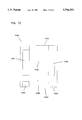
- FIG. 1 is an exploded view of a disk drive suitable for practicing the present invention
- FIG. 2 illustrates a prior art slider having etched recesses with protrusions
- FIG. 3 illustrates the features of an air bearing slider which includes landing pads according to the invention to provide smooth contact surfaces
- FIG. 4 shows a rear view of the slider of FIG. 3
- FIG. 5 illustrates another exemplary slider design with landing pads according to the present invention
- FIG. 6 illustrates the features of an air bearing slider with landing pads level with the air bearing surfaces according to the present invention
- FIG. 7 illustrates the features of an alternative two rail air bearing slider design with a landing pad according to the present invention
- FIG. 8 illustrates a tri-pad air bearing slider design with landing pads according to the present invention
- FIG. 9 illustrates an air bearing slider having a generally U-shaped rail configuration with landing pads disposed proximate the leading edge of the slider
- FIG. 10 illustrates an air bearing slider design having a central, trailing transducer pad with adjacent landing pads according to the present invention.
- FIG. 11 illustrates an alternative two rail air bearing slider with a single landing pad according to the present invention.
- the present invention provides an air bearing slider design which protects the disk surface during shock or loading but which does not contribute to air bearing or fly height performance.
- FIG. 1 is an exploded view of a disk drive 100.
- the disk drive 100 includes a housing 112 and a housing cover 114 which, after assembly, is mounted within a frame 116.
- Mounted within the housing is a spindle shaft 122.
- Rotatably attached to the spindle shaft 122 are a number of disks 124.
- eight disks 124 are attached to the spindle shaft 122 in spaced apart relation.
- the disks 124 rotate on spindle shaft 122 which is powered by a motor (not shown).
- Information is written on or read from the disks 124 by heads or magnetic transducers (not shown) which are supported by sliders 126.
- sliders in accordance with the invention are coupled to the suspensions or load springs 128.
- the load springs 128 are attached to separate arms 130 on an E block or comb 132.
- the E block or comb 132 is attached at one end of an actuator arm assembly 136.
- the actuator arm assembly 136 is rotatably attached within the housing 112 on an actuator shaft 138.
- the invention is not limited to the data storage device described above.
- FIG. 2 illustrates a prior art slider design 200 which may be used in a storage device as described above with reference to FIG. 1.
- the prior art slider design 200 has an etched surface 202 with sharp protrusions 204 resulting to the etching process mentioned earlier.
- the etched surface 202 of the support structure appears to have sharp protrusions 204 when viewed under magnification as illustrated in the enlarged view 206 of the etched surface 202.
- these sharp protrusions 204 can impact on the disk surface resulting in a thermal asperity and a loss of customer data.
- suspension static attitude offsets due to manufacturing tolerances can lead to similar damage when utilizing a load/unload mechanism or during the actuator/disk stack merge operation. These conditions can result in the sharp protrusions 204 of the rough etched surface corner touching down on the disk surface and inducing a thermal asperity. Contact between the rough surfaces and the disk result in damage to the disk surface, loss of customer data or both.
- FIG. 3 illustrates the features of an air bearing slider 300 which includes landing pads 340, 342 to provide smooth contact surfaces for air bearing sliders 300.
- the air bearing slider 300 includes a leading edge 302 and a trailing edge 304 disposed at opposite ends of a longitudinal axis running the length of the slider.
- the air bearing slider 300 further includes a left rail 306, a right rail 308 and a connecting crossbar 310 therebetween.
- the left rail 306 and right rail 308 are substantially parallel to sides 312, 314 of the air bearing slider 300 which are in turn parallel to the longitudinal axis.
- the crossbar 310 may be either perpendicular or oblique to the sides 312, 314 of the slider 300. Extending from the center crossbar 310 is a center rail 330.
- Two generally U-shaped recessed areas 320, 322 are formed between the center rail 330 and the two side rails 306, 308 for creating negative pressure as the disk spins beneath the air bearing slider 300.
- a broader area 324 for supporting a magnetic element 332 is provided at the trailing edge 304 of the center rail 330.
- landing pads 340, 342 are provided at the outer corners of the air bearing slider 300. The size and shape of the landing pads 340, 342 are chosen to provide a smoother contact surface than the etched surface 350 of the support structure during loading or unloading, or in the event of shock, while not contributing significantly to the air bearing or fly height performance.
- the surface of the landing pads 440, 442 is recessed from the plane of the air bearing surface 460, e.g., by an ion milling process in the preferred embodiment. This insures that the minimum spacing remains located near the transducer 432 while the slider is flying.
- FIG. 5 illustrates another exemplary slider design 500 with ion-milled landing pads 540, 542 according to the present invention.
- additional ion milled features are also illustrated, e.g., transverse pressurization contour (TPC) steps 570, stepped tapers 572, and trailing edge (TE) rail shaping 574.
- TPC transverse pressurization contour
- TE trailing edge
- the surface roughness of ion milled surfaces is substantially smoother than the RIE surface 550. Accordingly, the ion-milled landing pads 540, 542 contacting the disk will produces much less damage and fewer thermal asperities than that which would result from the RIE surface 550 contacting the disk surface.
- the depth of the recess between the surface of the landing pads 540, 542 and the plane 560 of the air bearing surface can be selected to be consistent with the modified air bearing surface features formed by the ion milling procedure, such as the TPC steps 570, stepped tapers 572, or trailing edge rail shaping 574 in order to minimize manufacturing costs.
- the process for forming the landing pads 540, 542 is not limited to ion milling, but rather any alternative process capable of providing a smooth surface can be utilized for fabrication of the landing pads 540, 542.
- the surface of the landing pads 540, 542 need not be recessed from the plane 560 of the air bearing surface.
- the advantages of the landing pads 540, 542 may be offset by the added variability of the minimum flying height due to slider roll.
- landing pad features 540, 542 may be applied to a large number of air bearing geometries, and that the number and location of these features are not limited.
- Other exemplary, alternative embodiments are illustrated with reference to FIGS. 6-11.
- FIG. 6 illustrates the features of an air bearing slider 600 with landing pads 640, 642 according to the present invention that is similar to the design described with reference to FIG. 3.
- the air bearing slider 600 includes a leading edge 602 and a trailing edge 604 disposed at opposite ends of a longitudinal axis running the length of the slider.
- the air bearing slider 600 further includes a left rail 606, a right rail 608 and a crossbar 610 therebetween.
- the left rail 606 and right rail 608 are substantially parallel to sides 612, 614 of the air bearing slider 600 which are in turn parallel to the longitudinal axis.
- the crossbar 610 may be either perpendicular or oblique to the sides 612, 614 of the slider 600. Extending from the crossbar 610 is a center rail 630.
- Two generally U-shaped recessed areas 620, 622 are formed between the center rail 630 and the two side rails 606, 608 for creating negative pressure as the disk spins beneath the air bearing slider 600.
- a broader area 624 for mounting a magnetic element is provided at the trailing edge 604 of the center rail 630.
- landing pads 640, 642 are provided at the outer corners of the air bearing surface. Again, the size and shape of the landing pads 640, 642 are chosen to provide a smoother contact surface during shock or loading. Further, the landing pads may or may not be recessed from the air bearing surfaces as desired.
- FIG. 7 illustrates the features of an alternative air bearing slider 700 with a landing pad 740 according to the present invention.
- the air bearing slider 700 includes two rails 706, 708, each including a subrail 780.
- a channel 782 is formed between the two side rails 706, 708.
- the right rail 708 includes a main portion 784 which extends substantially to the trailing edge 704.
- the landing pad 740 is disposed opposite the main portion 784 of the right side rail 708 also substantially at the trailing edge 704.
- FIG. 8 illustrates a tri-pad air bearing slider design 800 with landing pads 840, 842 according to the present invention.
- the slider includes two front pads 806, 808 disposed substantially at the leading edge 802 of the slider 800.
- a central, trailing pad 886 is disposed substantially at the trailing edge 804.
- Landing pads 840, 842 are provided at the outer corners of the air bearing slider 800 on opposite sides of the trailing pad 886. Again, the size and shape of the landing pads 840, 842 are chosen to provide a smoother contact surface during shock or loading and unloading. Further, the landing pads may be recessed from the air bearing surfaces if contribution to the air bearing or fly height performance is not desired.
- FIG. 9 illustrates an air bearing slider 900 having a generally U-shaped rail 990 configuration with landing pads 940, 942 disposed proximate the leading edge of the slider 900.
- the air bearing slider 900 includes a leading edge 902 and a trailing edge 904 disposed at opposite ends of a longitudinal axis running the length of the slider 900.
- the U-shaped rail 990 includes a left rail 906 and a right rail 908 connected by a crossbar 910 therebetween.
- a generally U-shaped recessed area 920 is formed between the two side rails 906, 908 for creating negative pressure as the disk spins beneath the air bearing slider 900.
- the crossbar 910 includes a central tapered section 992 extending substantially to the leading edge 902.
- the landing pads 940, 942 are provided at the outer corners of the air bearing slider 900 at the leading edge 902 of the slider 900 on opposite sides of the central tapered section 992.
- the size and shape of the landing pads 940, 942 are chosen to provide a smoother contact surface during shock or loading. Further, the landing pads 940, 942 may be recessed from the air bearing surfaces if contribution to the air bearing or fly height performance is not desired. Still further, the landing pads 940, 942 may be tapered to customize fly height performance if desired.
- FIG. 10 illustrates a two rail negative pressure design of an air bearing slider 1000 with a central, trailing transducer pad 1086 and landing pads 1040, 1042 according to the present invention.
- the air bearing slider 1000 has a leading edge 1002, a tailing edge 1004, and two side rails 1006, 1008.
- a recessed negative pressure area 1020 is formed between the two side rails 1006, 1008.
- the central, trailing pad 1086 is disposed substantially at the trailing edge 1004.
- Landing pads 1040, 1042 are provided at the outer corners of the air bearing slider 1000 on opposite sides of the trailing pad 1086. Again, the size and shape of the landing pads 1040, 1042 are chosen to provide a smoother contact surface during shock or loading and unloading. Further, the landing pads may be recessed from the air bearing surfaces if contribution to the air bearing or fly height performance is not desired.
- FIG. 11 illustrates the features of an alternative air bearing slider 1100 with a landing pad 1140 according to the present invention.
- the air bearing slider 1100 includes two rails 1106, 1108 similar to that described with reference to FIG. 10.
- the right rail 1108 extends substantially to the trailing edge 1104.
- the landing pad 1140 is disposed opposite the trailing portion of the right side rail 1108 also substantially at the trailing edge 1104.
Abstract
Description
Claims (29)
Priority Applications (1)
| Application Number | Priority Date | Filing Date | Title |
|---|---|---|---|
| US08/732,201 US5796551A (en) | 1996-10-16 | 1996-10-16 | Landing pads for air bearing sliders and method for making the same |
Applications Claiming Priority (1)
| Application Number | Priority Date | Filing Date | Title |
|---|---|---|---|
| US08/732,201 US5796551A (en) | 1996-10-16 | 1996-10-16 | Landing pads for air bearing sliders and method for making the same |
Publications (1)
| Publication Number | Publication Date |
|---|---|
| US5796551A true US5796551A (en) | 1998-08-18 |
Family
ID=24942597
Family Applications (1)
| Application Number | Title | Priority Date | Filing Date |
|---|---|---|---|
| US08/732,201 Expired - Lifetime US5796551A (en) | 1996-10-16 | 1996-10-16 | Landing pads for air bearing sliders and method for making the same |
Country Status (1)
| Country | Link |
|---|---|
| US (1) | US5796551A (en) |
Cited By (47)
| Publication number | Priority date | Publication date | Assignee | Title |
|---|---|---|---|---|
| US6004472A (en) * | 1997-05-14 | 1999-12-21 | International Business Machines Corporation | Dual etch step process for making a three etch depth air bearing slider |
| US6055128A (en) * | 1997-05-14 | 2000-04-25 | International Business Machines Corporation | Dual etch step pad air bearing design with three etch depths |
| US6125005A (en) * | 1997-12-30 | 2000-09-26 | International Business Machines Corporation | Altitude insensitive air bearing using pitch compensation for data storage application |
| US6144528A (en) * | 1998-10-26 | 2000-11-07 | Read-Rite Corporation | Air bearing slider with reduced stiction |
| US6144529A (en) * | 1997-03-25 | 2000-11-07 | Tdk Corporation | Slider with negative and positive pressure generating portions and head including the same |
| US6229671B1 (en) * | 1997-09-22 | 2001-05-08 | Seagate Technology Llc | Shock pads for a slider for a data storage system |
| US6229672B1 (en) * | 1998-10-19 | 2001-05-08 | Read-Rite Corporation | High gram load air bearing geometry for a tripad slider |
| US6236543B1 (en) | 1999-01-29 | 2001-05-22 | Read-Rite Corporation | Durable landing pads for an air-bearing slider |
| US20020012200A1 (en) * | 2000-06-20 | 2002-01-31 | Zine-Eddine Boutaghou | Slider with predicted tipped position |
| US6356412B1 (en) * | 1999-09-30 | 2002-03-12 | Read-Rite Corporation | Air bearing facilitating load/unload of a magnetic read/write head |
| US6373658B2 (en) * | 1998-03-19 | 2002-04-16 | Seagate Technology Llc | Optimum location for slider landing pads |
| US20020126417A1 (en) * | 2001-03-12 | 2002-09-12 | International Business Machines Corporation | Head shock resistance and head load/unload protection for reducing disk errors and defects, and enhancing data integrity of disk drives |
| US6462909B1 (en) | 2000-05-09 | 2002-10-08 | Seagate Technology Llc | Disc head slider having wear-resistant pads for enhanced damping |
| US6483668B2 (en) * | 1999-01-22 | 2002-11-19 | Seagate Technology Llc | Edge contact protection feature for a disc drive head |
| US6487049B1 (en) * | 1998-12-23 | 2002-11-26 | Iomega Corporation | Drive heads for storage media drive with displaced pair of sensors |
| US6490135B1 (en) | 1999-12-02 | 2002-12-03 | Seagate Technology Llc | Disc drive assembly having side rail-channeled air bearing for ramp load-unload applications |
| US6504682B1 (en) | 1999-12-02 | 2003-01-07 | Seagate Technology Llc | Disc head slider having recessed, channeled rails for reduced stiction |
| US6510027B1 (en) | 2000-02-11 | 2003-01-21 | Seagate Technology Llc | Disc head slider having highly damped bearing with multiple pressure gradiant-generating pads |
| US6515831B1 (en) | 2000-01-11 | 2003-02-04 | Seagate Technology Llc | Disc head slider having leading and trailing channeled rails for enhanced damping |
| US6529347B2 (en) | 2000-10-13 | 2003-03-04 | Seagate Technology Llc | Disc drive slider having textured pads |
| US6529346B2 (en) | 2000-01-21 | 2003-03-04 | Alps Electric Co., Ltd. | Magnetic head slider with protrusion on surface facing recording medium |
| US6535353B2 (en) * | 1998-03-20 | 2003-03-18 | Seagate Technology Llc | Capped polymeric load/unload pads |
| US6536265B1 (en) | 1999-12-02 | 2003-03-25 | Seagate Technology Llc | Micro-textured glide sliders for super-smooth media |
| US6542334B2 (en) | 1998-11-18 | 2003-04-01 | Seagate Technology Llc | Edge structure for slider-disc interface and method of manufacture therefor |
| US6549378B2 (en) | 2001-01-16 | 2003-04-15 | Hitachi Global Storage Technologies Netherlands B.V. | Magnetic disk drive with offset load/unload tab |
| US6558771B1 (en) | 1999-08-27 | 2003-05-06 | Seagate Technology Llc | Textured magnetic media for use with low-flying padded heads |
| US6574074B2 (en) | 2001-01-16 | 2003-06-03 | International Business Machines Corporation | Air bearing surface design for inducing roll-bias during load/unload sequence |
| US6587308B2 (en) | 1999-01-29 | 2003-07-01 | Seagate Technology, Llc | Disc head slider having profiled convergent channel features |
| US20030148715A1 (en) * | 2000-07-13 | 2003-08-07 | Zine-Eddine Boutaghou | Apparatus for finishing a magnetic slider |
| US6606222B1 (en) | 1998-09-21 | 2003-08-12 | Seagate Technology Llc | Convergent channel, trenched disc head slider |
| US20030197978A1 (en) * | 1999-12-28 | 2003-10-23 | Tomoo Otsuka | Magnetic head slider having protrusions provided on the medium-facing surface and manufacturing method therefor |
| US6647612B1 (en) * | 1999-02-11 | 2003-11-18 | Seagate Technology Llc | Method for constructing an ultra-low-flying-height slider |
| US6657819B2 (en) | 1999-12-27 | 2003-12-02 | Alps Electric Co., Ltd. | Magnetic head having protrusion on medium opposing surface and magnetic recording apparatus |
| US6678119B1 (en) | 2000-04-12 | 2004-01-13 | Seagate Technology Llc | Disc head slider having rails with enclosed depressions |
| US20040012887A1 (en) * | 2002-07-17 | 2004-01-22 | Rajashankar Rajakumar | Head slider having convergent channel features with side opening |
| US20040085677A1 (en) * | 2002-11-04 | 2004-05-06 | Minggao Yao | System and method for preventing computer storage media surface contaminant accumulation and for preventing impact-related head/slider damage |
| US20040090709A1 (en) * | 2002-11-07 | 2004-05-13 | Seagate Technology Llc | Head slider having tilted protrusions for ramp load-unload applications |
| US6771468B1 (en) | 2001-10-22 | 2004-08-03 | Western Digital Corporation | Slider with high pitch-stiffness air bearing design |
| SG105525A1 (en) * | 2001-01-09 | 2004-08-27 | Hitachi Global Storage Tech | Slider, head assembly, and disk drive unit |
| US20040179289A1 (en) * | 2003-03-10 | 2004-09-16 | Hitachi Global Storage Technologies Netherlands B.V. | Method and apparatus for recovering load/unload zone real estate on data storage media in data storage devices to increase a data storage capacity thereof |
| US7038884B1 (en) | 2001-02-16 | 2006-05-02 | Maxtor Corporation | Flying-type disk drive slider with self-blending contact pad |
| US7106556B2 (en) | 2003-06-24 | 2006-09-12 | Seagate Technology Llc | Slider configured for rapid bearing stabilization during ramp load operations |
| US20080204936A1 (en) * | 2007-02-28 | 2008-08-28 | Weidong Huang | Slider air bearing with asymetric side rail |
| US20090109572A1 (en) * | 2007-10-31 | 2009-04-30 | Fujitsu Limited | HEAD SLIDER, HEAD GIMBAL ASSEMBLY and STORAGE APPARATUS |
| US20090141402A1 (en) * | 2007-11-30 | 2009-06-04 | Kabushiki Kaisha Toshiba | Head, head suspension assembly, and disk device provided with the same |
| US20110195275A1 (en) * | 2010-02-05 | 2011-08-11 | Seagate Technology Llc | Material deposition on transducing head |
| US10679656B1 (en) | 2019-05-03 | 2020-06-09 | Seagate Technology Llc | Magnetic heads for use in different fluid atmospheres, and related methods |
Citations (18)
| Publication number | Priority date | Publication date | Assignee | Title |
|---|---|---|---|---|
| JPS61160885A (en) * | 1985-01-09 | 1986-07-21 | Matsushita Electric Ind Co Ltd | Dynamic pressure type floating head |
| JPS62110680A (en) * | 1985-11-08 | 1987-05-21 | Matsushita Electric Ind Co Ltd | Floating type slider |
| JPH01133274A (en) * | 1987-11-18 | 1989-05-25 | Victor Co Of Japan Ltd | Floating magnetic head and its manufacture |
| JPH01211383A (en) * | 1988-02-19 | 1989-08-24 | Nec Corp | Negative pressure slider |
| US4894740A (en) * | 1988-09-28 | 1990-01-16 | International Business Machines Corporation | Magnetic head air bearing slider |
| JPH02235274A (en) * | 1989-03-08 | 1990-09-18 | Fujitsu Ltd | Magnetic recording head |
| US5062017A (en) * | 1990-05-25 | 1991-10-29 | Seagate Technology, Inc. | Hour-glass disk head slider |
| US5079657A (en) * | 1990-02-15 | 1992-01-07 | Applied Magnetics Corporation | Textured air bearing surface |
| JPH04195779A (en) * | 1990-11-26 | 1992-07-15 | Fujitsu Ltd | Manufacture of magnetic head slider |
| US5267109A (en) * | 1991-06-14 | 1993-11-30 | Seagate Technology, Inc. | Air bearing slider with relieved trailing edge |
| JPH06111508A (en) * | 1992-09-24 | 1994-04-22 | Alps Electric Co Ltd | Magnetic head |
| JPH06150283A (en) * | 1992-10-30 | 1994-05-31 | Nec Corp | Magnetic head slider |
| US5396386A (en) * | 1993-05-28 | 1995-03-07 | International Business Machines Corporation | Roll insensitive air bearing slider |
| US5406432A (en) * | 1993-10-07 | 1995-04-11 | Read-Rite Corporation | Air bearing magnetic head sliders with separate center rail segments |
| US5424888A (en) * | 1993-06-24 | 1995-06-13 | International Business Machines Corp. | Speed independent, air bearing slider |
| US5452151A (en) * | 1992-05-29 | 1995-09-19 | J. Money & Associates, Inc. | Data access module |
| US5572386A (en) * | 1984-11-13 | 1996-11-05 | Unisys Corporation | Slider for inhibiting stiction |
| US5625512A (en) * | 1995-03-21 | 1997-04-29 | International Business Machines Corporation | Air bearing slider deflection apparatus and method for fabricating same |
-
1996
- 1996-10-16 US US08/732,201 patent/US5796551A/en not_active Expired - Lifetime
Patent Citations (18)
| Publication number | Priority date | Publication date | Assignee | Title |
|---|---|---|---|---|
| US5572386A (en) * | 1984-11-13 | 1996-11-05 | Unisys Corporation | Slider for inhibiting stiction |
| JPS61160885A (en) * | 1985-01-09 | 1986-07-21 | Matsushita Electric Ind Co Ltd | Dynamic pressure type floating head |
| JPS62110680A (en) * | 1985-11-08 | 1987-05-21 | Matsushita Electric Ind Co Ltd | Floating type slider |
| JPH01133274A (en) * | 1987-11-18 | 1989-05-25 | Victor Co Of Japan Ltd | Floating magnetic head and its manufacture |
| JPH01211383A (en) * | 1988-02-19 | 1989-08-24 | Nec Corp | Negative pressure slider |
| US4894740A (en) * | 1988-09-28 | 1990-01-16 | International Business Machines Corporation | Magnetic head air bearing slider |
| JPH02235274A (en) * | 1989-03-08 | 1990-09-18 | Fujitsu Ltd | Magnetic recording head |
| US5079657A (en) * | 1990-02-15 | 1992-01-07 | Applied Magnetics Corporation | Textured air bearing surface |
| US5062017A (en) * | 1990-05-25 | 1991-10-29 | Seagate Technology, Inc. | Hour-glass disk head slider |
| JPH04195779A (en) * | 1990-11-26 | 1992-07-15 | Fujitsu Ltd | Manufacture of magnetic head slider |
| US5267109A (en) * | 1991-06-14 | 1993-11-30 | Seagate Technology, Inc. | Air bearing slider with relieved trailing edge |
| US5452151A (en) * | 1992-05-29 | 1995-09-19 | J. Money & Associates, Inc. | Data access module |
| JPH06111508A (en) * | 1992-09-24 | 1994-04-22 | Alps Electric Co Ltd | Magnetic head |
| JPH06150283A (en) * | 1992-10-30 | 1994-05-31 | Nec Corp | Magnetic head slider |
| US5396386A (en) * | 1993-05-28 | 1995-03-07 | International Business Machines Corporation | Roll insensitive air bearing slider |
| US5424888A (en) * | 1993-06-24 | 1995-06-13 | International Business Machines Corp. | Speed independent, air bearing slider |
| US5406432A (en) * | 1993-10-07 | 1995-04-11 | Read-Rite Corporation | Air bearing magnetic head sliders with separate center rail segments |
| US5625512A (en) * | 1995-03-21 | 1997-04-29 | International Business Machines Corporation | Air bearing slider deflection apparatus and method for fabricating same |
Cited By (70)
| Publication number | Priority date | Publication date | Assignee | Title |
|---|---|---|---|---|
| US6317294B1 (en) | 1997-03-25 | 2001-11-13 | Tdk Corporation | Slider with negative and multiple positive pressure generation portions and head including the same |
| US6144529A (en) * | 1997-03-25 | 2000-11-07 | Tdk Corporation | Slider with negative and positive pressure generating portions and head including the same |
| US6055128A (en) * | 1997-05-14 | 2000-04-25 | International Business Machines Corporation | Dual etch step pad air bearing design with three etch depths |
| US6004472A (en) * | 1997-05-14 | 1999-12-21 | International Business Machines Corporation | Dual etch step process for making a three etch depth air bearing slider |
| US6229671B1 (en) * | 1997-09-22 | 2001-05-08 | Seagate Technology Llc | Shock pads for a slider for a data storage system |
| US6125005A (en) * | 1997-12-30 | 2000-09-26 | International Business Machines Corporation | Altitude insensitive air bearing using pitch compensation for data storage application |
| US6373658B2 (en) * | 1998-03-19 | 2002-04-16 | Seagate Technology Llc | Optimum location for slider landing pads |
| US6535353B2 (en) * | 1998-03-20 | 2003-03-18 | Seagate Technology Llc | Capped polymeric load/unload pads |
| US6606222B1 (en) | 1998-09-21 | 2003-08-12 | Seagate Technology Llc | Convergent channel, trenched disc head slider |
| US6229672B1 (en) * | 1998-10-19 | 2001-05-08 | Read-Rite Corporation | High gram load air bearing geometry for a tripad slider |
| US6144528A (en) * | 1998-10-26 | 2000-11-07 | Read-Rite Corporation | Air bearing slider with reduced stiction |
| US6542334B2 (en) | 1998-11-18 | 2003-04-01 | Seagate Technology Llc | Edge structure for slider-disc interface and method of manufacture therefor |
| US6487049B1 (en) * | 1998-12-23 | 2002-11-26 | Iomega Corporation | Drive heads for storage media drive with displaced pair of sensors |
| US6483668B2 (en) * | 1999-01-22 | 2002-11-19 | Seagate Technology Llc | Edge contact protection feature for a disc drive head |
| US6236543B1 (en) | 1999-01-29 | 2001-05-22 | Read-Rite Corporation | Durable landing pads for an air-bearing slider |
| US6587308B2 (en) | 1999-01-29 | 2003-07-01 | Seagate Technology, Llc | Disc head slider having profiled convergent channel features |
| US6647612B1 (en) * | 1999-02-11 | 2003-11-18 | Seagate Technology Llc | Method for constructing an ultra-low-flying-height slider |
| US6884526B1 (en) | 1999-08-27 | 2005-04-26 | Seagate Technology Llc | Textured magnetic media for use with low-flying padded heads |
| US6558771B1 (en) | 1999-08-27 | 2003-05-06 | Seagate Technology Llc | Textured magnetic media for use with low-flying padded heads |
| US6583961B2 (en) | 1999-09-30 | 2003-06-24 | Read-Rite Corporation | Air bearing facilitating load/unload of a magnetic read/write head |
| US6356412B1 (en) * | 1999-09-30 | 2002-03-12 | Read-Rite Corporation | Air bearing facilitating load/unload of a magnetic read/write head |
| US6490135B1 (en) | 1999-12-02 | 2002-12-03 | Seagate Technology Llc | Disc drive assembly having side rail-channeled air bearing for ramp load-unload applications |
| US6504682B1 (en) | 1999-12-02 | 2003-01-07 | Seagate Technology Llc | Disc head slider having recessed, channeled rails for reduced stiction |
| US6536265B1 (en) | 1999-12-02 | 2003-03-25 | Seagate Technology Llc | Micro-textured glide sliders for super-smooth media |
| US6657819B2 (en) | 1999-12-27 | 2003-12-02 | Alps Electric Co., Ltd. | Magnetic head having protrusion on medium opposing surface and magnetic recording apparatus |
| US20030197978A1 (en) * | 1999-12-28 | 2003-10-23 | Tomoo Otsuka | Magnetic head slider having protrusions provided on the medium-facing surface and manufacturing method therefor |
| US6728069B2 (en) | 1999-12-28 | 2004-04-27 | Alps Electric Co., Ltd. | Magnetic head slider having protrusions with high abrasion resistance provided on the medium-facing surface and manufacturing method therefor |
| US6515831B1 (en) | 2000-01-11 | 2003-02-04 | Seagate Technology Llc | Disc head slider having leading and trailing channeled rails for enhanced damping |
| US6529346B2 (en) | 2000-01-21 | 2003-03-04 | Alps Electric Co., Ltd. | Magnetic head slider with protrusion on surface facing recording medium |
| US6510027B1 (en) | 2000-02-11 | 2003-01-21 | Seagate Technology Llc | Disc head slider having highly damped bearing with multiple pressure gradiant-generating pads |
| US6678119B1 (en) | 2000-04-12 | 2004-01-13 | Seagate Technology Llc | Disc head slider having rails with enclosed depressions |
| US6462909B1 (en) | 2000-05-09 | 2002-10-08 | Seagate Technology Llc | Disc head slider having wear-resistant pads for enhanced damping |
| US20020012200A1 (en) * | 2000-06-20 | 2002-01-31 | Zine-Eddine Boutaghou | Slider with predicted tipped position |
| US6882504B2 (en) | 2000-06-20 | 2005-04-19 | Seagate Technology Llc | Micro textured slider with predicted tipped position |
| US20030148715A1 (en) * | 2000-07-13 | 2003-08-07 | Zine-Eddine Boutaghou | Apparatus for finishing a magnetic slider |
| US6843705B2 (en) | 2000-07-13 | 2005-01-18 | Seagate Technology Llc | Apparatus for finishing a magnetic slider |
| US6529347B2 (en) | 2000-10-13 | 2003-03-04 | Seagate Technology Llc | Disc drive slider having textured pads |
| SG105525A1 (en) * | 2001-01-09 | 2004-08-27 | Hitachi Global Storage Tech | Slider, head assembly, and disk drive unit |
| US6785093B2 (en) | 2001-01-09 | 2004-08-31 | Hitachi Global Storage Technologies, Inc. Netherlands B.V | Slider, head assembly, and disk drive unit |
| US6574074B2 (en) | 2001-01-16 | 2003-06-03 | International Business Machines Corporation | Air bearing surface design for inducing roll-bias during load/unload sequence |
| US6549378B2 (en) | 2001-01-16 | 2003-04-15 | Hitachi Global Storage Technologies Netherlands B.V. | Magnetic disk drive with offset load/unload tab |
| US7262938B1 (en) | 2001-02-16 | 2007-08-28 | Maxtor Corporation | Flying-type disk drive slider with self-blending contact pad |
| US7038884B1 (en) | 2001-02-16 | 2006-05-02 | Maxtor Corporation | Flying-type disk drive slider with self-blending contact pad |
| US20060082926A1 (en) * | 2001-03-12 | 2006-04-20 | Feliss Norbert A | Head shock resistance and head load/unload protection for reducing disk errors and defects, and enhancing data integrity of disk drives |
| US7283329B2 (en) | 2001-03-12 | 2007-10-16 | Hitachi Global Storage Technologies Netherlands Bv | Head shock resistance and head load/unload protection for reducing disk errors and defects, and enhancing data integrity of disk drives |
| US20020126417A1 (en) * | 2001-03-12 | 2002-09-12 | International Business Machines Corporation | Head shock resistance and head load/unload protection for reducing disk errors and defects, and enhancing data integrity of disk drives |
| US7167343B2 (en) | 2001-03-12 | 2007-01-23 | Hitachi Global Storage Technologies Netherlands Bv | Head shock resistance and head load/unload protection for reducing disk errors and defects, and enhancing data integrity of disk drives |
| US20060082925A1 (en) * | 2001-03-12 | 2006-04-20 | Feliss Norbert A | Head shock resistance and head load/unload protection for reducing disk errors and defects, and enhancing data integrity of disk drives |
| US6995952B2 (en) * | 2001-03-12 | 2006-02-07 | Hitachi Global Storage Technologies Netherlands B.V. | Head shock resistance and head load/unload protection for reducing disk errors and defects, and enhancing data integrity of disk drives |
| US6771468B1 (en) | 2001-10-22 | 2004-08-03 | Western Digital Corporation | Slider with high pitch-stiffness air bearing design |
| US20040012887A1 (en) * | 2002-07-17 | 2004-01-22 | Rajashankar Rajakumar | Head slider having convergent channel features with side opening |
| US6937440B2 (en) | 2002-07-17 | 2005-08-30 | Seagate Technology Llc | Head slider having convergent channel features with side opening |
| US7119991B2 (en) | 2002-11-04 | 2006-10-10 | Sae Magnetics (H.K.) Ltd. | System and method for preventing computer storage media surface contaminant accumulation and for preventing impact-related head/slider damage |
| US20040085677A1 (en) * | 2002-11-04 | 2004-05-06 | Minggao Yao | System and method for preventing computer storage media surface contaminant accumulation and for preventing impact-related head/slider damage |
| WO2004042727A1 (en) * | 2002-11-04 | 2004-05-21 | Sae Magnetics (H. K.) Ltd. | System and method for preventing computer storage media surface contaminant accumulation and for preventing impact-related head/slider damage |
| US20040090709A1 (en) * | 2002-11-07 | 2004-05-13 | Seagate Technology Llc | Head slider having tilted protrusions for ramp load-unload applications |
| US6989965B2 (en) | 2002-11-07 | 2006-01-24 | Seagate Technology Llc | Head slider having tilted protrusions for ramp load-unload applications |
| US6937419B2 (en) | 2003-03-10 | 2005-08-30 | Hitachi Global Storage Technologies Netherlands B.V. | Method and apparatus for recovering load/unload zone real estate on data storage media in data storage devices to increase a data storage capacity thereof |
| US20040179289A1 (en) * | 2003-03-10 | 2004-09-16 | Hitachi Global Storage Technologies Netherlands B.V. | Method and apparatus for recovering load/unload zone real estate on data storage media in data storage devices to increase a data storage capacity thereof |
| US7106556B2 (en) | 2003-06-24 | 2006-09-12 | Seagate Technology Llc | Slider configured for rapid bearing stabilization during ramp load operations |
| US7817378B2 (en) * | 2007-02-28 | 2010-10-19 | Hitachi Global Storage Technologies Netherlands, B.V. | Slider air bearing with asymetric side rail |
| US20080204936A1 (en) * | 2007-02-28 | 2008-08-28 | Weidong Huang | Slider air bearing with asymetric side rail |
| US20090109572A1 (en) * | 2007-10-31 | 2009-04-30 | Fujitsu Limited | HEAD SLIDER, HEAD GIMBAL ASSEMBLY and STORAGE APPARATUS |
| US20090141402A1 (en) * | 2007-11-30 | 2009-06-04 | Kabushiki Kaisha Toshiba | Head, head suspension assembly, and disk device provided with the same |
| US20110090597A1 (en) * | 2007-11-30 | 2011-04-21 | Kabushiki Kaisha Toshiba | Head with slider suppressing back flow, head suspension assembly, and disk device provided with the same |
| US8179638B2 (en) * | 2007-11-30 | 2012-05-15 | Kabushiki Kaisha Toshiba | Head with slider suppressing back flow, head suspension assembly, and disk device provided with the same |
| US20110195275A1 (en) * | 2010-02-05 | 2011-08-11 | Seagate Technology Llc | Material deposition on transducing head |
| US8139323B2 (en) | 2010-02-05 | 2012-03-20 | Seagate Technology Llc | Material deposition on transducing head |
| US10679656B1 (en) | 2019-05-03 | 2020-06-09 | Seagate Technology Llc | Magnetic heads for use in different fluid atmospheres, and related methods |
| US11355143B2 (en) | 2019-05-03 | 2022-06-07 | Seagate Technology Llc | Magnetic heads for use in different fluid atmospheres, and related methods |
Similar Documents
| Publication | Publication Date | Title |
|---|---|---|
| US5796551A (en) | Landing pads for air bearing sliders and method for making the same | |
| US5396386A (en) | Roll insensitive air bearing slider | |
| US5737151A (en) | Roll insensitive air bearing slider | |
| US5870250A (en) | Method and apparatus for improving file capacity using different flying height profiles | |
| US5777825A (en) | Negative pressure step pad air bearing design and method for making the same | |
| CA2071453C (en) | Slider air bearing surface with angled rail configuration | |
| US6700727B1 (en) | Slider and method for actively controlling crown curvature | |
| US4285019A (en) | Contoured magnetic recording head/slider assembly | |
| US7515384B2 (en) | Method and apparatus for providing a three stepped air bearing having a funnel structure for controlling air flow to improve fly height performance | |
| KR100288869B1 (en) | Design of a double etch step pad type air bearing with three etch depths | |
| US6333835B1 (en) | Step pad air bearing for load/unload mechanism | |
| US5761004A (en) | Air bearing slider with offset crossbars to reduce roll | |
| US5561570A (en) | Dynamically loaded suspension for contact recording | |
| US20020071216A1 (en) | Disc drive having an air bearing surface with trenched contact protection feature | |
| US6226151B1 (en) | Contact slider for magneto-resistive heads | |
| US5825587A (en) | Shallow etch air bearing surface features for optimized transducer spacing | |
| US20020191340A1 (en) | Disc head slider having an air bearing surface for improved damping | |
| US5774304A (en) | Disc head slider having center rail with asymmetric edge steps | |
| US5825588A (en) | Roll insensitive air bearing slider | |
| US6574074B2 (en) | Air bearing surface design for inducing roll-bias during load/unload sequence | |
| US5796550A (en) | Method and apparatus for providing diverging rail edge geometry for air bearing slider | |
| US7092213B1 (en) | Multiple level surface configuration for a sub-ambient pressure air bearing slider | |
| US6141181A (en) | Magnetic disk apparatus with floating sliders having obliquely mounted rails | |
| US7251107B2 (en) | Method and apparatus for providing an air bearing pad having improved roll angle sigma |
Legal Events
| Date | Code | Title | Description |
|---|---|---|---|
| AS | Assignment |
Owner name: INTERNATIONAL BUSINESS MACHINES CORPORATION, NEW Y Free format text: ASSIGNMENT OF ASSIGNORS INTEREST;ASSIGNOR:SAMUELSON, LAURENCE S.;REEL/FRAME:008280/0331 Effective date: 19960827 |
|
| AS | Assignment |
Owner name: IBM CORPORATION, NEW YORK Free format text: ASSIGNMENT OF ASSIGNORS INTEREST;ASSIGNORS:BERGMAN, LAWRENCE D.;GERTH, JOHN A.;ROBINSON, JOHN T.;AND OTHERS;REEL/FRAME:008424/0603;SIGNING DATES FROM 19961025 TO 19970116 |
|
| STCF | Information on status: patent grant |
Free format text: PATENTED CASE |
|
| FEPP | Fee payment procedure |
Free format text: PAYOR NUMBER ASSIGNED (ORIGINAL EVENT CODE: ASPN); ENTITY STATUS OF PATENT OWNER: LARGE ENTITY |
|
| FPAY | Fee payment |
Year of fee payment: 4 |
|
| AS | Assignment |
Owner name: MARIANA HDD B.V., NETHERLANDS Free format text: ASSIGNMENT OF ASSIGNORS INTEREST;ASSIGNOR:INTERNATIONAL BUSINESS MACHINES CORPORATION;REEL/FRAME:013663/0348 Effective date: 20021231 |
|
| AS | Assignment |
Owner name: HITACHI GLOBAL STORAGE TECHNOLOGIES NETHERLANDS B. Free format text: CHANGE OF NAME;ASSIGNOR:MARIANA HDD B.V.;REEL/FRAME:013746/0146 Effective date: 20021231 |
|
| FPAY | Fee payment |
Year of fee payment: 8 |
|
| FEPP | Fee payment procedure |
Free format text: PAYER NUMBER DE-ASSIGNED (ORIGINAL EVENT CODE: RMPN); ENTITY STATUS OF PATENT OWNER: LARGE ENTITY Free format text: PAYOR NUMBER ASSIGNED (ORIGINAL EVENT CODE: ASPN); ENTITY STATUS OF PATENT OWNER: LARGE ENTITY |
|
| FPAY | Fee payment |
Year of fee payment: 12 |
|
| AS | Assignment |
Owner name: HGST, NETHERLANDS B.V., NETHERLANDS Free format text: CHANGE OF NAME;ASSIGNOR:HGST, NETHERLANDS B.V.;REEL/FRAME:029341/0777 Effective date: 20120723 Owner name: HGST NETHERLANDS B.V., NETHERLANDS Free format text: CHANGE OF NAME;ASSIGNOR:HITACHI GLOBAL STORAGE TECHNOLOGIES NETHERLANDS B.V.;REEL/FRAME:029341/0777 Effective date: 20120723 |
|
| AS | Assignment |
Owner name: WESTERN DIGITAL TECHNOLOGIES, INC., CALIFORNIA Free format text: ASSIGNMENT OF ASSIGNORS INTEREST;ASSIGNOR:HGST NETHERLANDS B.V.;REEL/FRAME:040818/0551 Effective date: 20160831 |