US5786575A - Wrap tool for magnetic field-responsive heat-fusible pipe couplings - Google Patents
Wrap tool for magnetic field-responsive heat-fusible pipe couplings Download PDFInfo
- Publication number
- US5786575A US5786575A US08/575,214 US57521495A US5786575A US 5786575 A US5786575 A US 5786575A US 57521495 A US57521495 A US 57521495A US 5786575 A US5786575 A US 5786575A
- Authority
- US
- United States
- Prior art keywords
- flange
- coil
- wrap tool
- sleeve portion
- electrical conductors
- Prior art date
- Legal status (The legal status is an assumption and is not a legal conclusion. Google has not performed a legal analysis and makes no representation as to the accuracy of the status listed.)
- Expired - Lifetime
Links
Images


Classifications
-
- H—ELECTRICITY
- H05—ELECTRIC TECHNIQUES NOT OTHERWISE PROVIDED FOR
- H05B—ELECTRIC HEATING; ELECTRIC LIGHT SOURCES NOT OTHERWISE PROVIDED FOR; CIRCUIT ARRANGEMENTS FOR ELECTRIC LIGHT SOURCES, IN GENERAL
- H05B6/00—Heating by electric, magnetic or electromagnetic fields
- H05B6/02—Induction heating
- H05B6/36—Coil arrangements
-
- B—PERFORMING OPERATIONS; TRANSPORTING
- B23—MACHINE TOOLS; METAL-WORKING NOT OTHERWISE PROVIDED FOR
- B23K—SOLDERING OR UNSOLDERING; WELDING; CLADDING OR PLATING BY SOLDERING OR WELDING; CUTTING BY APPLYING HEAT LOCALLY, e.g. FLAME CUTTING; WORKING BY LASER BEAM
- B23K13/00—Welding by high-frequency current heating
- B23K13/01—Welding by high-frequency current heating by induction heating
- B23K13/02—Seam welding
- B23K13/025—Seam welding for tubes
-
- B—PERFORMING OPERATIONS; TRANSPORTING
- B29—WORKING OF PLASTICS; WORKING OF SUBSTANCES IN A PLASTIC STATE IN GENERAL
- B29C—SHAPING OR JOINING OF PLASTICS; SHAPING OF MATERIAL IN A PLASTIC STATE, NOT OTHERWISE PROVIDED FOR; AFTER-TREATMENT OF THE SHAPED PRODUCTS, e.g. REPAIRING
- B29C65/00—Joining or sealing of preformed parts, e.g. welding of plastics materials; Apparatus therefor
- B29C65/02—Joining or sealing of preformed parts, e.g. welding of plastics materials; Apparatus therefor by heating, with or without pressure
- B29C65/34—Joining or sealing of preformed parts, e.g. welding of plastics materials; Apparatus therefor by heating, with or without pressure using heated elements which remain in the joint, e.g. "verlorenes Schweisselement"
- B29C65/36—Joining or sealing of preformed parts, e.g. welding of plastics materials; Apparatus therefor by heating, with or without pressure using heated elements which remain in the joint, e.g. "verlorenes Schweisselement" heated by induction
- B29C65/3604—Joining or sealing of preformed parts, e.g. welding of plastics materials; Apparatus therefor by heating, with or without pressure using heated elements which remain in the joint, e.g. "verlorenes Schweisselement" heated by induction characterised by the type of elements heated by induction which remain in the joint
- B29C65/362—Joining or sealing of preformed parts, e.g. welding of plastics materials; Apparatus therefor by heating, with or without pressure using heated elements which remain in the joint, e.g. "verlorenes Schweisselement" heated by induction characterised by the type of elements heated by induction which remain in the joint comprising at least a single wire, e.g. in the form of a winding
-
- B—PERFORMING OPERATIONS; TRANSPORTING
- B29—WORKING OF PLASTICS; WORKING OF SUBSTANCES IN A PLASTIC STATE IN GENERAL
- B29C—SHAPING OR JOINING OF PLASTICS; SHAPING OF MATERIAL IN A PLASTIC STATE, NOT OTHERWISE PROVIDED FOR; AFTER-TREATMENT OF THE SHAPED PRODUCTS, e.g. REPAIRING
- B29C65/00—Joining or sealing of preformed parts, e.g. welding of plastics materials; Apparatus therefor
- B29C65/02—Joining or sealing of preformed parts, e.g. welding of plastics materials; Apparatus therefor by heating, with or without pressure
- B29C65/34—Joining or sealing of preformed parts, e.g. welding of plastics materials; Apparatus therefor by heating, with or without pressure using heated elements which remain in the joint, e.g. "verlorenes Schweisselement"
- B29C65/36—Joining or sealing of preformed parts, e.g. welding of plastics materials; Apparatus therefor by heating, with or without pressure using heated elements which remain in the joint, e.g. "verlorenes Schweisselement" heated by induction
- B29C65/3668—Joining or sealing of preformed parts, e.g. welding of plastics materials; Apparatus therefor by heating, with or without pressure using heated elements which remain in the joint, e.g. "verlorenes Schweisselement" heated by induction characterised by the means for supplying heat to said heated elements which remain in the join, e.g. special induction coils
-
- B—PERFORMING OPERATIONS; TRANSPORTING
- B29—WORKING OF PLASTICS; WORKING OF SUBSTANCES IN A PLASTIC STATE IN GENERAL
- B29C—SHAPING OR JOINING OF PLASTICS; SHAPING OF MATERIAL IN A PLASTIC STATE, NOT OTHERWISE PROVIDED FOR; AFTER-TREATMENT OF THE SHAPED PRODUCTS, e.g. REPAIRING
- B29C66/00—General aspects of processes or apparatus for joining preformed parts
- B29C66/01—General aspects dealing with the joint area or with the area to be joined
- B29C66/05—Particular design of joint configurations
- B29C66/10—Particular design of joint configurations particular design of the joint cross-sections
- B29C66/11—Joint cross-sections comprising a single joint-segment, i.e. one of the parts to be joined comprising a single joint-segment in the joint cross-section
- B29C66/112—Single lapped joints
- B29C66/1122—Single lap to lap joints, i.e. overlap joints
-
- B—PERFORMING OPERATIONS; TRANSPORTING
- B29—WORKING OF PLASTICS; WORKING OF SUBSTANCES IN A PLASTIC STATE IN GENERAL
- B29C—SHAPING OR JOINING OF PLASTICS; SHAPING OF MATERIAL IN A PLASTIC STATE, NOT OTHERWISE PROVIDED FOR; AFTER-TREATMENT OF THE SHAPED PRODUCTS, e.g. REPAIRING
- B29C66/00—General aspects of processes or apparatus for joining preformed parts
- B29C66/50—General aspects of joining tubular articles; General aspects of joining long products, i.e. bars or profiled elements; General aspects of joining single elements to tubular articles, hollow articles or bars; General aspects of joining several hollow-preforms to form hollow or tubular articles
- B29C66/51—Joining tubular articles, profiled elements or bars; Joining single elements to tubular articles, hollow articles or bars; Joining several hollow-preforms to form hollow or tubular articles
- B29C66/52—Joining tubular articles, bars or profiled elements
- B29C66/522—Joining tubular articles
- B29C66/5221—Joining tubular articles for forming coaxial connections, i.e. the tubular articles to be joined forming a zero angle relative to each other
-
- B—PERFORMING OPERATIONS; TRANSPORTING
- B29—WORKING OF PLASTICS; WORKING OF SUBSTANCES IN A PLASTIC STATE IN GENERAL
- B29C—SHAPING OR JOINING OF PLASTICS; SHAPING OF MATERIAL IN A PLASTIC STATE, NOT OTHERWISE PROVIDED FOR; AFTER-TREATMENT OF THE SHAPED PRODUCTS, e.g. REPAIRING
- B29C66/00—General aspects of processes or apparatus for joining preformed parts
- B29C66/50—General aspects of joining tubular articles; General aspects of joining long products, i.e. bars or profiled elements; General aspects of joining single elements to tubular articles, hollow articles or bars; General aspects of joining several hollow-preforms to form hollow or tubular articles
- B29C66/51—Joining tubular articles, profiled elements or bars; Joining single elements to tubular articles, hollow articles or bars; Joining several hollow-preforms to form hollow or tubular articles
- B29C66/52—Joining tubular articles, bars or profiled elements
- B29C66/522—Joining tubular articles
- B29C66/5229—Joining tubular articles involving the use of a socket
-
- B—PERFORMING OPERATIONS; TRANSPORTING
- B29—WORKING OF PLASTICS; WORKING OF SUBSTANCES IN A PLASTIC STATE IN GENERAL
- B29C—SHAPING OR JOINING OF PLASTICS; SHAPING OF MATERIAL IN A PLASTIC STATE, NOT OTHERWISE PROVIDED FOR; AFTER-TREATMENT OF THE SHAPED PRODUCTS, e.g. REPAIRING
- B29C66/00—General aspects of processes or apparatus for joining preformed parts
- B29C66/80—General aspects of machine operations or constructions and parts thereof
- B29C66/81—General aspects of the pressing elements, i.e. the elements applying pressure on the parts to be joined in the area to be joined, e.g. the welding jaws or clamps
- B29C66/812—General aspects of the pressing elements, i.e. the elements applying pressure on the parts to be joined in the area to be joined, e.g. the welding jaws or clamps characterised by the composition, by the structure, by the intensive physical properties or by the optical properties of the material constituting the pressing elements, e.g. constituting the welding jaws or clamps
- B29C66/8122—General aspects of the pressing elements, i.e. the elements applying pressure on the parts to be joined in the area to be joined, e.g. the welding jaws or clamps characterised by the composition, by the structure, by the intensive physical properties or by the optical properties of the material constituting the pressing elements, e.g. constituting the welding jaws or clamps characterised by the composition of the material constituting the pressing elements, e.g. constituting the welding jaws or clamps
-
- B—PERFORMING OPERATIONS; TRANSPORTING
- B23—MACHINE TOOLS; METAL-WORKING NOT OTHERWISE PROVIDED FOR
- B23K—SOLDERING OR UNSOLDERING; WELDING; CLADDING OR PLATING BY SOLDERING OR WELDING; CUTTING BY APPLYING HEAT LOCALLY, e.g. FLAME CUTTING; WORKING BY LASER BEAM
- B23K2101/00—Articles made by soldering, welding or cutting
- B23K2101/04—Tubular or hollow articles
- B23K2101/06—Tubes
-
- B—PERFORMING OPERATIONS; TRANSPORTING
- B29—WORKING OF PLASTICS; WORKING OF SUBSTANCES IN A PLASTIC STATE IN GENERAL
- B29C—SHAPING OR JOINING OF PLASTICS; SHAPING OF MATERIAL IN A PLASTIC STATE, NOT OTHERWISE PROVIDED FOR; AFTER-TREATMENT OF THE SHAPED PRODUCTS, e.g. REPAIRING
- B29C65/00—Joining or sealing of preformed parts, e.g. welding of plastics materials; Apparatus therefor
- B29C65/02—Joining or sealing of preformed parts, e.g. welding of plastics materials; Apparatus therefor by heating, with or without pressure
- B29C65/34—Joining or sealing of preformed parts, e.g. welding of plastics materials; Apparatus therefor by heating, with or without pressure using heated elements which remain in the joint, e.g. "verlorenes Schweisselement"
- B29C65/36—Joining or sealing of preformed parts, e.g. welding of plastics materials; Apparatus therefor by heating, with or without pressure using heated elements which remain in the joint, e.g. "verlorenes Schweisselement" heated by induction
- B29C65/3672—Joining or sealing of preformed parts, e.g. welding of plastics materials; Apparatus therefor by heating, with or without pressure using heated elements which remain in the joint, e.g. "verlorenes Schweisselement" heated by induction characterised by the composition of the elements heated by induction which remain in the joint
- B29C65/3676—Joining or sealing of preformed parts, e.g. welding of plastics materials; Apparatus therefor by heating, with or without pressure using heated elements which remain in the joint, e.g. "verlorenes Schweisselement" heated by induction characterised by the composition of the elements heated by induction which remain in the joint being metallic
-
- B—PERFORMING OPERATIONS; TRANSPORTING
- B29—WORKING OF PLASTICS; WORKING OF SUBSTANCES IN A PLASTIC STATE IN GENERAL
- B29C—SHAPING OR JOINING OF PLASTICS; SHAPING OF MATERIAL IN A PLASTIC STATE, NOT OTHERWISE PROVIDED FOR; AFTER-TREATMENT OF THE SHAPED PRODUCTS, e.g. REPAIRING
- B29C66/00—General aspects of processes or apparatus for joining preformed parts
- B29C66/70—General aspects of processes or apparatus for joining preformed parts characterised by the composition, physical properties or the structure of the material of the parts to be joined; Joining with non-plastics material
- B29C66/71—General aspects of processes or apparatus for joining preformed parts characterised by the composition, physical properties or the structure of the material of the parts to be joined; Joining with non-plastics material characterised by the composition of the plastics material of the parts to be joined
Definitions
- This invention relates to tools for coupling oscillating magnetic fields to induce selected frequency electric currents in heating elements positioned in selected regions of plastic couplings.
- Plastic pipes made of polyethylene or other polymers are used for many purposes, including natural gas distribution. Joining and repairing such pipes has been facilitated by the development of advanced self-regulating, constant-temperature fusion joining systems for plastic pipes. Typically, such fusion joining systems use hollow plastic couplings to join adjacent plastic pipes by fusing the ends of the pipes circumferentially to a plastic coupling. Raychem Corporation of Menlo Park, Calif., manufactures the SmartHeatTM coupling, one type of plastic pipe coupling. General details regarding SmartHeatTM couplings and their operation are provided in U.S. Pat. No. 4,256,945 (1981) entitled "Alternating Current Electrically Resistive Heating Element Having Intrinsic Temperature Control," which is incorporated by reference into this application.
- Such a pipe coupling has magnetic field responsive heating elements at least partially embedded in the cylindrical walls of the coupling.
- the pipe coupling is used to fuse two pipes together.
- the end portions of two plastic pipes are inserted into the pipe coupling, and an external tool applies a suitable frequency, time-varying magnetic field to induce electric currents in the heating elements.
- the heating elements become sufficiently hot to melt adjacent portions of the plastic pipe coupling material and fuse the pipe coupling circumferentially to the end portions of the pipes.
- the heating elements in the pipe coupling can self-regulate and can include solid wires which have an electrically conductive non-magnetic core which has a low resistance. Copper is one example of such a non-magnetic core.
- the heating elements generally have a more highly electrically resistant outer perimeter of one or more magnetic materials which surround the copper core.
- the heating element can include loaded materials for induction heating, as disclosed in U.S. Pat. No. 5,378,879, which is incorporated by reference into this application.
- a heating element in a pipe coupling can self-regulate about a particular temperature.
- heating elements can be nonregulating as well. Whether regulating or nonregulating, the heating element becomes sufficiently hot to melt the interior surface of the pipe coupling and an abutting pipe surface, causing fusion between the plastic pipe and the pipe coupling.
- the self-regulating feature of the coupling controls and regulates fusion while preventing damage to the plastic pipe and coupling.
- the fusion process is tolerant of some misalignment between the pipe and coupling being joined. Further, the end portions of two pipes being joined by a coupling need not abut one another because the pipe coupling can bridge a gap between such pipes.
- the uniform distribution of oscillating magnetic fields according to this invention ensures uniform heating of the coupling heating elements.
- a wrap tool which has separate working and return coils at least partially positioned about a pipe coupling having magnetically-coupled heating elements.
- the wrap tool produces uniformly oscillating magnetic fields and consequent regularity in heat distribution for fusion of the pipe coupling to inserted plastic pipes.
- the uniformly oscillating magnetic fields induce correspondingly uniformly oscillating electric currents within the heating elements of the pipe coupling, producing a uniform heat distribution within the pipe coupling.
- the wrap tool has an electric winding including working and return coils which are axially separated with respect to each other and are interlinked in flanges of a flexible sleeve harness.
- the flexible sleeve harness holds the wires of the working and return coils in spaced relationship to each other and is at least partially positioned about the circumference of a substantially cylindrical plastic pipe coupling.
- the flanges of the wrap tool can be separated to permit installation of the wrap tool about the pipe coupling and plastic pipes for fusion joinder with oscillating magnetic fields.
- the return coil serves as a second working coil.
- a first working coil is positioned about the external surface of one portion of a coupling, and a second working coil is positioned about the external surface of another portion of the coupling.
- wrap tool is described as having a working coil and a return coil, it is understood that the return coil can serve as a working coil which induces electric current in a heating element.
- the wrap tool can include a unitary, flexible sleeve wire harness having extension flanges of a suitable flexible material such as urethane or another elastomeric, electrically insulative material, to enable convenient installation by permitting the flanges to be separated to allow them to be pulled over the plastic coupling.
- a suitable flexible material such as urethane or another elastomeric, electrically insulative material
- the flanges contain wire links interconnecting corresponding wire turns of the working and return coils, which are axially spaced apart with respect to each other in the sleeve harness.
- One flange contains the wire links carrying electric current from the working coil to the return coil, and the other flange contains corresponding wire links carrying electric currents from the return coil to the working coil.
- the working coil induces electric currents in the heating elements of the plastic pipe coupling, and the return coil provides circuit completion.
- the flanges are physically coupled with respect to each other after being wrapped about a pipe coupling.
- a power supply is then energized to provide the needed drive currents at the appropriate operational frequency to heat and fuse the pipe coupling to the pipes.
- the corresponding, oppositely directed electric currents in the wire links of the adjacent flanges of the working and return coils produce bucking magnetic fields which cancel each other during operation.
- the flange regions can be planar or curved.
- the coil wires in the flange regions are supported by first and second correspondingly contoured rigid boards of polycarbonate or selected laminates, for example.
- a suitable capacitor, or distributed capacitors connected in series with the inductive working and return coils are provided for connection with a source of suitable frequency alternating electric power.
- the distribution of capacitors can be within a combined winding which includes working and return coil segments and the electric links therebetween.
- FIG. 1a is a perspective view of a wrap tool according to one preferred embodiment of this invention, mounted on a plastic pipe coupling joining a first plastic pipe and a second plastic pipe;
- FIG. 1b is a perspective view of the wrap tool according to one preferred embodiment of this invention, with the flanges of the wrap tool in an open state;
- FIG. 1c is a perspective view of a prior art pipe coupling having first and second embedded magnetic induction heaters for enabling the pipe coupling to be controllably fused to first and second insertable plastic pipe ends;
- FIG. 2a is a side schematic view showing the general winding scheme of the working coil and return coil and the connecting wires between corresponding wire turns in the working coil and return coil, which are embedded in the inner surface of the flanges of the wrap tool, according to one preferred embodiment of this invention;
- FIG. 2b is a side schematic view of the working coil and the return coil and connecting wires in the flanges of the wrap tool according to one preferred embodiment of this invention, particularly showing first corresponding wire layer and second corresponding wire layer carrying oppositely directed electric currents to establish power saving bucking magnetic fields in the connecting wires interconnecting the working coil and return coil;
- FIG. 2c is an end schematic view of the working coil and return coil and connecting wires in the flanges of the wrap tool according to one preferred embodiment of this invention
- FIG. 3a is a schematic view of the working coil and return coil and their interconnections according to the present invention, projected on an inner surface of the wrap tool;
- FIG. 3b is a modification of the schematic view of FIG. 3a which shows in dashed lines the portion of the working coil and return coil and connecting wires between the working coil and the return coil of the wrap tool;
- FIG. 3c is a conceptual illustration of the wrap tool coils and connecting wires according to FIG. 3b according to one preferred embodiment of this invention, showing in phantom the portions of the coils and connecting wires which are on the backside of the pipe coupling at installation, and showing the bucking current flows which result in a cancellation of magnetic fields in the vicinity of the flanges which contain the corresponding connecting wires;
- FIG. 4 is a perspective view of the wrap tool according to one preferred embodiment of this invention, installed on a selected pipe coupling, showing a single turn of the wrap tool following a path through the working coil and return coil with oppositely directed adjacent alternating currents in the flanges of the wrap tool that cancel opposing magnetic fields;
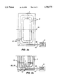
- FIG. 5a is a diagram of the electric circuitry of one preferred embodiment of this invention, including a capacitor for reducing the voltage requirements of the wrap tool during fusion operation;
- FIG. 5b is a diagram of the electric circuitry of another preferred embodiment of this invention, which includes a split winding straddling a capacitor for minimizing peak voltages in the wrap tool during fusion operation;
- FIG. 6 is a schematic view of a wrap tool, according to another preferred embodiment of this invention.
- FIG. 1a shows a perspective view of a wrap tool 2 according to one preferred embodiment of this invention, including an electric winding 3 installed about a plastic pipe coupling 4 into which the ends of first plastic pipe 5 and second plastic pipe 6 are positioned.
- Wrap tool 2 includes a flexible sleeve harness including inner surface 7 and outer surface 8.
- Electric winding 3 includes working coil 9 and return coil 10 and electric links 11 connecting segments of working coil 9 and return coil 10 to each other electrically.
- Wrap tool 2 further includes first flange 20 and second flange 21 for securing corresponding individual electric links 11 in a magnetically opposing configuration.
- first flange 20 and second flange 21 extend substantially tangentially outward from the circumference of wrap tool 2.
- a tangential direction from the circumference of wrap tool 2 is defined as any plane tangential to a cylinder concentric with the axis of wrap tool 2.
- Such tangentially extending first flange 20 and second flange 21 are beneficial for installing wrap tool 2 around pipes located near flat surfaces, because the cylindrical body of wrap tool 2 is essentially an extension of one of first flange 20 or second flange 21, which can easily be stopped under a selected pipe adjacent the flat surface.
- first flange 20 and second flange-21 extend radially outward from the center of wrap tool 2.
- Wrap tool 2 includes a sleeve harness of a flexible elastomeric material such as urethane, for example.
- Rigid board 22 is preferably embedded in first flange 20 and rigid board 23 is preferably embedded in second flange 21 to provide support and ease of manual handling during installation and removal of wrap tool 2 with respect to pipe coupling 4 and plastic pipes 5 and 6. This is particularly useful after pipes 5 and 6 have been inserted into pipe coupling 4, and it is no longer possible to slip wrap tool 2 over an end of pipe coupling 4.
- first flange 20 and second flange 21 are matingly coupled with one flange inner surface engaging the other flange inner surface, or by wrapping one flange under the other flange, according to another preferred embodiment of this invention.
- the inner surface of one flange is coupled to the outer surface of the other flange during fusion operation.
- First flange 20 and second flange 21 are engageable in flat, curved, and overlapped versions, according to this invention.
- flange 22 includes tabs 30, 31 and flange 23 includes tabs 32, 33.
- flange 22 includes tabs 30, 31 and flange 23 includes tabs 32, 33.
- tabs 30, 31 are offset from respective tabs 32, 33 to permit an operator's adjacent fingers to bear against neighboring offset tabs.
- FIG. 1a further shows electric winding 3 embedded within wrap tool 2 at or near the inner surface 7 of wrap 10 tool 2. Actual embedding is not essential, but electric winding 3 is preferably secured at or near selected surfaces of wrap tool 2. An adhesive can be used to secure electric winding 3 with respect to wrap tool 2. Electric winding 3 is provided with electricity at selected high frequency power levels from a power source 41 which is connected through first electric current path 42 and second electric current path 43, one of which paths may include a ground or a common connection.
- electric winding 3 is constructed of Litz wire, which is a known multistrand twisted configuration of fine wires, for example, insulated copper or silver wire. Such wire reduces resistance losses during operation, particularly resistance losses at 400 kilohertz, the preferred operational frequency of the SmartHeatTM coupling. Litz wire is particularly flexible and convenient for ease of manufacture. It is apparent that electric winding 3 can comprise other types of wires known to those skilled in the art which are suitable for the intended purpose of generating oscillating magnetic fields.
- both path 42 and path 43 are electric lines.
- Electric winding 3 has first end 44 and second end 45 which are connected to first electric current path 42 and second electric current path 43, respectively.
- Electric winding 3 includes a selected plurality of turns in its progress to and from current paths 42 and 43.
- a single turn of electric winding 3 begins by traversing working coil 9, first flange 20, return coil 10, and second flange 21, where the turn is connected to a next turn of electric winding 3 for a repeat of the same traversal pattern. Each turn follows the same general contour of inner surface 7 of wrap tool 2.
- Electric winding 3 includes a predetermined plurality of turns.
- an axial spacing between adjacent turns of return coil 10 of wrap tool 2 is less than the axial spacing between adjacent turns in the working coil 9.
- Such reduced spatial separation induces more intense magnetic fields in return coil 10, but as there are preferably no heating elements within the circumference of return coil 10 according to such preferred embodiment, no undesired heat is produced.
- the spacing between adjacent turns in working coil 9 is selected to produce a level of alternating magnetic power which induces desired electric current levels in heating elements within pipe coupling 4.
- return coil 10 serves as a second working coil
- the axial spacing between adjacent turns in the second working coil can be the same or different from the axial spacing between adjacent turns in working coil 9.
- FIG. 1b is a perspective view of wrap tool 2 according to one preferred embodiment of this invention, in an open state before or after mounting on pipe coupling 4.
- Such open state permits positioning wrap tool 2 about a selected end of pipes 5 or 6.
- the tangential extension of first flange 20 and second flange 21 from wrap tool 2 permits positioning wrap tool 2 about pipes 5, 6 and pipe coupling 4 even when pipes 5, 6 are very close to a wall or other surface or obstruction.
- FIG. 1c is a perspective view of a prior art pipe coupling 4 having an inner surface 50 in which are embedded magnetically activable heaters 51 and 52 for enabling pipe coupling 4 to be controllably fused to selected plastic pipe ends (not shown).
- FIG. 2a is a side schematic view of working coil 9 and return coil 10 and first electric links 9' in first flange 20 and second electric links 10' in second flange 21 of wrap tool 2, according to one preferred embodiment of this invention. Further shown are ends 44 and 45 which connect working coil 9 through respective paths 42 and 43 to power supply 41 to produce an oscillating electric current in electric winding 3 which induces magnetic fields in the regions around the wires of working coil 9.
- FIG. 2b is another side view of working coil 9 and return coil 10, and first electric links 9' in first flange 20 and second electric links 10' in second flange 21 of wrap tool 2 according to this invention. Particularly shown are first electric links 9' and second electric links 10' between working coil 9 and return coil 10.
- FIG. 2c is an end view of working coil 9 and return coil 10 and first electric links 9' in first flange 20 and second electric links 10' in second flange 21 of the wrap tool 2 according to this invention. Further shown are wire ends 44 and 45 which connect working coil 9 through respective paths 42 and 43 to power supply 41 which produces a varying electric current in electric winding 3 which induces magnetic fields in the regions around the wires of working coil 9. Particularly shown are first electric links 9' and second electric links 10' between working coil 9 and return coil 10.
- First flange 20 and second flange 21 can be perpendicular to or tangential to a circumference of wrap tool 2.
- the inner surface of first flange 20 is engageable with the inner surface of second flange 21.
- First electric links 9' and second electric links 10' are secured with the engaging surfaces of first flange 20 and second flange 21.
- the magnetic fields of first electric links 9' and second electric links 10' are each cancelled by the other.
- FIG. 6 is a schematic view of wrap tool 2 according to another preferred embodiment of this invention.
- inner and outer surfaces of first flange 20 and second flange 21 can overlap each other in engagement.
- Second flange 21 can have radial projections which mate with openings in first flange 20 to secure second flange 21 with respect to first flange 20 during the heating process.
- FIG. 3a is a flat projection of the region of inner surface 7 of wrap tool 2 according to one preferred embodiment of this invention.
- FIG. 3a shows an unwrapped version of the coil distribution pattern of electric winding 3 secured with respect to inner surface 7 of wrap tool 2.
- Central dotted line 70 represents the zenith of inner surface 7 of wrap tool 2. This is the location at which a turn of electric winding 3 is half-way through working coil 9 or half-way through return coil 10.
- First flange 20 and second flange 21 respectively include first electric links 9' and second electric links 10'.
- FIG. 3b is a modification of the flat projection of FIG. 3a showing in dashed lines the portion of electric winding 3 of wrap tool 2 which is wrapped onto the backside of pipe coupling 4 which is fused to selected pipes 5, 6, according to this invention.
- the dashed lines indicate that the far side of electric winding 3 in inner surface 7 is being illustrated above dotted line 70, and the dark lines of FIG. 3b emphasize that the near side of electric winding 3 in inner surface 7 is being shown below dotted line 70.
- FIG. 3c is a conceptual illustration of a wrapped version of electric winding 3 and inner surface 7 showing in phantom first electric links 9' of electric winding 3 which is on the backside of pipe coupling 4, according to one preferred embodiment of this invention.
- FIG. 3c additionally shows the adjacency of corresponding first electric links 9' and second electric links 10' of electric winding 3 in flanges 20 and 21 which results in the beneficial cancellation of magnetic fields called bucking.
- Bucking occurs because the alternating currents in first flange 20 and second flange 21 are oppositely directed. Bucking is accomplished with precision according to the present invention, by producing the bucking field with a continuation of the same wire, on a wire by wire basis, which produced the magnetic field being cancelled.
- the opposite currents of dark and dashed coil lines in working coil 9 and return coil 10 respectively do not cancel, because the dark and dashed coil lines are separated by pipe coupling 4 (not shown).
- FIG. 4 is a perspective view of wrap tool 2 showing a single turn of electric winding 3 connected to power supply 41 and following a selected path of the turn through working coil 9 and return coil 10.
- the path of the turn includes first flange 20 and second flange 21 having respective differently directed alternating currents which cancel each other out to minimize tool external magnetic fields in the flange regions of wrap tool 2.
- FIG. 5a is a diagram of electric winding 3 according to one preferred embodiment of this invention including a capacitor 60, for minimizing the peak voltage produced by power supply 41.
- Capacitor 60 is shown connected to power source 41 through paths 42 and 43 and electric winding 3. The selection of the precise capacitance required depends on the inductance of working coil 9 and return coil 10. Optimally, capacitor 60 is selected to establish a resonance condition at the operational frequency intended for electric winding 3 to accomplish fusion operation.
- the embodiment shown in FIG. 5a relies upon a lumped single capacitor 60. According to another preferred embodiment of this invention, the capacitance represented by capacitor 60 is distributed within working coil 9.
- a selected number of capacitances can be placed at two or more locations of working coil 9 and/or return coil 10.
- the wire-to-wire spacing of electric winding portions is kept to a minimum between first flange 20 and second flange 21 to reduce inductance for flat, curved, and overlapped versions of flanges 20, 21.
- FIG. 5b is a diagram of a split coil version of one preferred embodiment of this invention in which electric winding 3 includes first coil winding portion 3' and second coil winding portion 3" which are each connected to capacitor 60.
- Capacitor 60 can be connected substantially halfway along the length of electric winding 3, and can be fabricated in a selected one of first flange 20 or second flange 21 (not shown).
Abstract
Description
Claims (20)
Priority Applications (3)
| Application Number | Priority Date | Filing Date | Title |
|---|---|---|---|
| US08/575,214 US5786575A (en) | 1995-12-20 | 1995-12-20 | Wrap tool for magnetic field-responsive heat-fusible pipe couplings |
| AU11067/97A AU1106797A (en) | 1995-12-20 | 1996-12-19 | Wrap tool for magnetic field-responsive heat-fusible pipe couplings |
| PCT/IB1996/001453 WO1997023118A1 (en) | 1995-12-20 | 1996-12-19 | Wrap tool for magnetic field-responsive heat-fusible pipe couplings |
Applications Claiming Priority (1)
| Application Number | Priority Date | Filing Date | Title |
|---|---|---|---|
| US08/575,214 US5786575A (en) | 1995-12-20 | 1995-12-20 | Wrap tool for magnetic field-responsive heat-fusible pipe couplings |
Publications (1)
| Publication Number | Publication Date |
|---|---|
| US5786575A true US5786575A (en) | 1998-07-28 |
Family
ID=24299393
Family Applications (1)
| Application Number | Title | Priority Date | Filing Date |
|---|---|---|---|
| US08/575,214 Expired - Lifetime US5786575A (en) | 1995-12-20 | 1995-12-20 | Wrap tool for magnetic field-responsive heat-fusible pipe couplings |
Country Status (3)
| Country | Link |
|---|---|
| US (1) | US5786575A (en) |
| AU (1) | AU1106797A (en) |
| WO (1) | WO1997023118A1 (en) |
Cited By (22)
| Publication number | Priority date | Publication date | Assignee | Title |
|---|---|---|---|---|
| US6278096B1 (en) * | 1999-08-03 | 2001-08-21 | Shell Oil Company | Fabrication and repair of electrically insulated flowliness by induction heating |
| US6323468B1 (en) * | 2000-04-25 | 2001-11-27 | The Boeing Company | Static coil apparatus and method for welding thermoplastic composite structures |
| US6346690B1 (en) * | 1998-05-05 | 2002-02-12 | Illinois Tool Works Inc. | Induction heating system with a flexible coil |
| US6410895B2 (en) * | 1999-05-12 | 2002-06-25 | Ju-Oh Inc. | Induction heating coil unit for manifold in hot runner mold |
| US20040084443A1 (en) * | 2002-11-01 | 2004-05-06 | Ulrich Mark A. | Method and apparatus for induction heating of a wound core |
| US6875966B1 (en) | 2004-03-15 | 2005-04-05 | Nexicor Llc | Portable induction heating tool for soldering pipes |
| WO2006090092A1 (en) * | 2005-02-25 | 2006-08-31 | Glynwed Pipe Systems Ltd | Method for joining multi-layered pipe |
| WO2006090157A3 (en) * | 2005-02-25 | 2007-01-11 | Glynwed Pipe Systems Ltd | Method for joining multi-layered pipe |
| US20080216960A1 (en) * | 2007-03-06 | 2008-09-11 | Huettinger Elektronik Gmbh + Co. Kg | Flexible Inductor for the Inductive Sealing of Packages |
| US20090256349A1 (en) * | 2006-05-05 | 2009-10-15 | Pierre Strubin | Method and device for connecting tubes made out of thermoplastic material |
| WO2012094765A1 (en) * | 2011-01-14 | 2012-07-19 | Shawcor Ltd. | Induction heating apparatus for pipeline connections |
| US20140151368A1 (en) * | 2012-12-03 | 2014-06-05 | Ajax Tocco Magnethermic Corporation | Induction heating coil and process for fusion weld joining thermoplastic composite pipe |
| JP2014229395A (en) * | 2013-05-20 | 2014-12-08 | パナソニック株式会社 | Induction heating apparatus |
| WO2015108959A1 (en) * | 2014-01-14 | 2015-07-23 | Johnson Controls Technology Company | Internal inductive heating of additive manufactured parts and tools |
| CN105033437A (en) * | 2015-08-17 | 2015-11-11 | 应城骏腾发自动焊接装备有限公司 | Welding method of pipe connector |
| US20160227611A1 (en) * | 2013-09-10 | 2016-08-04 | Magma Global Limited | Heating method |
| US20160354852A1 (en) * | 2014-01-23 | 2016-12-08 | General Electric Technology Gmbh | Method for brazing rotor windings |
| US20170164777A1 (en) * | 2015-12-10 | 2017-06-15 | Spectrum Brands, Inc. | Induction cooktop |
| JP2017159315A (en) * | 2016-03-08 | 2017-09-14 | 株式会社東芝 | Induction heating device, bonding method, bonding component, and rotary electric machine with the same component |
| US20180139851A1 (en) * | 2013-05-22 | 2018-05-17 | International Business Machines Corporation | Manufacturing a product using a soldering process |
| KR20190074279A (en) * | 2016-10-20 | 2019-06-27 | 케 켈릿 쿤스트슈토프베르크 게엠베하 | METHOD AND APPARATUS FOR INDUCTION WELDING PLASTIC OBJECTS USING A COIL ASSEMBLY CONTAINING A FLEXIBLE COIL |
| CN111864499A (en) * | 2020-07-28 | 2020-10-30 | 国网山东省电力公司寿光市供电公司 | Cable butt welding device and method |
Families Citing this family (1)
| Publication number | Priority date | Publication date | Assignee | Title |
|---|---|---|---|---|
| AT510265B1 (en) * | 2010-12-14 | 2012-03-15 | Ke Kelit Kunststoffwerk Gmbh | DEVICE FOR THE INDUCTIVE WELDING OF THE THERMOPLASTIC MANTEL TUBE OF A REMOTE HEATING PIPE WITH A THERMOPLASTIC PLASTIC MUFF |
Citations (37)
| Publication number | Priority date | Publication date | Assignee | Title |
|---|---|---|---|---|
| FR750400A (en) * | 1932-05-06 | 1933-08-09 | Ugine Infra | Device for power factor compensation of induction furnaces |
| US2052010A (en) * | 1934-08-04 | 1936-08-25 | Chrysler Corp | Induction heating apparatus |
| US2452801A (en) * | 1944-06-07 | 1948-11-02 | Sunbeam Corp | Apparatus for high-frequency induction heating |
| US2620433A (en) * | 1942-06-01 | 1952-12-02 | Ohio Crankshaft Co | Coil for differential heat-treatment |
| US2739829A (en) * | 1950-08-05 | 1956-03-27 | American Viscose Corp | Plastic pipe joint |
| US3062940A (en) * | 1958-02-17 | 1962-11-06 | Sud West Chemie G M B H | Welding fitting |
| US3238346A (en) * | 1963-08-05 | 1966-03-01 | George P Savko | Apparatus for making joint between thermo plastic pipe and fittings thereof |
| US3472987A (en) * | 1965-08-31 | 1969-10-14 | Acec | Process for heating by induction |
| US3688233A (en) * | 1971-03-12 | 1972-08-29 | Westinghouse Electric Corp | Electrical inductive apparatus having serially interconnected coils |
| US3688236A (en) * | 1971-03-12 | 1972-08-29 | Westinghouse Electric Corp | Electrical inductive apparatus having serially interconnected windings |
| US3725630A (en) * | 1971-12-20 | 1973-04-03 | Cycle Dyne Inc | Inductive coil for heating a loop of conductive material |
| US3755644A (en) * | 1972-06-27 | 1973-08-28 | Growth Int Inc | High frequency induction heating apparatus |
| US4010536A (en) * | 1973-04-04 | 1977-03-08 | Toshio Fujita | Method of adjusting two concentric windings in electrical induction devices |
| US4048458A (en) * | 1976-05-21 | 1977-09-13 | Illinois Tool Works Inc. | Induction heating core structure and method of heating |
| US4145591A (en) * | 1976-01-24 | 1979-03-20 | Nitto Chemical Industry Co., Ltd. | Induction heating apparatus with leakage flux reducing means |
| WO1980002124A1 (en) * | 1979-04-05 | 1980-10-16 | Haxey Eng Ltd | Methods for joining together thermoplastics pipes and pipe fittings |
| US4256945A (en) * | 1979-08-31 | 1981-03-17 | Iris Associates | Alternating current electrically resistive heating element having intrinsic temperature control |
| US4259654A (en) * | 1978-05-02 | 1981-03-31 | Asea Aktiebolag | Flux control in tape windings |
| US4388510A (en) * | 1981-06-12 | 1983-06-14 | Commercial Resins Company | Heating collar with quadrafilar windings |
| US4402309A (en) * | 1981-10-22 | 1983-09-06 | Donald L. Morton & Associates | Therapeutic magnetic electrode |
| DE3217300A1 (en) * | 1982-05-07 | 1983-11-10 | Christoph Dipl.-Ing. 3000 Bern Müller | Device for joining two rubber band ends by adhesion |
| US4442331A (en) * | 1981-01-22 | 1984-04-10 | Dai Ichi High Frequency Company, Ltd. | Method and apparatus of induction heating a metallic elongated material having different thickness sections |
| US4546210A (en) * | 1982-06-07 | 1985-10-08 | Hitachi, Ltd. | Litz wire |
| US4629844A (en) * | 1984-08-28 | 1986-12-16 | The Electricity Council | Induction heater having an alternating current conductor |
| US4695712A (en) * | 1983-06-27 | 1987-09-22 | Metcal, Inc. | Flexible autoregulating heater with a latching mechanism |
| US4745264A (en) * | 1984-03-06 | 1988-05-17 | Metcal, Inc. | High efficiency autoregulating heater |
| US4778971A (en) * | 1986-05-23 | 1988-10-18 | Kabushiki Kaisha Meidensha | Induction heating apparatus |
| JPS63272535A (en) * | 1987-05-01 | 1988-11-10 | Nippon Denso Co Ltd | Heating device for magnetic induction bonding |
| US4914267A (en) * | 1982-12-01 | 1990-04-03 | Metcal, Inc. | Connector containing fusible material and having intrinsic temperature control |
| US5101086A (en) * | 1990-10-25 | 1992-03-31 | Hydro-Quebec | Electromagnetic inductor with ferrite core for heating electrically conducting material |
| US5107095A (en) * | 1982-12-01 | 1992-04-21 | Metcal, Inc. | Clam shell heater employing high permeability material |
| US5304767A (en) * | 1992-11-13 | 1994-04-19 | Gas Research Institute | Low emission induction heating coil |
| US5338920A (en) * | 1990-11-30 | 1994-08-16 | Metcal, Inc. | Method of manufacturing and joining electro-fusion fitting |
| US5349165A (en) * | 1992-04-16 | 1994-09-20 | Gas Research Institute | Induction heater system for fusing plastics |
| US5352871A (en) * | 1991-02-20 | 1994-10-04 | Metcal Inc | System and method for joining plastic materials |
| US5378879A (en) * | 1993-04-20 | 1995-01-03 | Raychem Corporation | Induction heating of loaded materials |
| US5412184A (en) * | 1992-04-16 | 1995-05-02 | Gas Research Institute | Industion heating tool |
Family Cites Families (1)
| Publication number | Priority date | Publication date | Assignee | Title |
|---|---|---|---|---|
| GB9225617D0 (en) * | 1992-12-08 | 1993-01-27 | Hepworth Building Prod | Joint and method of forming a joint |
-
1995
- 1995-12-20 US US08/575,214 patent/US5786575A/en not_active Expired - Lifetime
-
1996
- 1996-12-19 WO PCT/IB1996/001453 patent/WO1997023118A1/en active Application Filing
- 1996-12-19 AU AU11067/97A patent/AU1106797A/en not_active Abandoned
Patent Citations (37)
| Publication number | Priority date | Publication date | Assignee | Title |
|---|---|---|---|---|
| FR750400A (en) * | 1932-05-06 | 1933-08-09 | Ugine Infra | Device for power factor compensation of induction furnaces |
| US2052010A (en) * | 1934-08-04 | 1936-08-25 | Chrysler Corp | Induction heating apparatus |
| US2620433A (en) * | 1942-06-01 | 1952-12-02 | Ohio Crankshaft Co | Coil for differential heat-treatment |
| US2452801A (en) * | 1944-06-07 | 1948-11-02 | Sunbeam Corp | Apparatus for high-frequency induction heating |
| US2739829A (en) * | 1950-08-05 | 1956-03-27 | American Viscose Corp | Plastic pipe joint |
| US3062940A (en) * | 1958-02-17 | 1962-11-06 | Sud West Chemie G M B H | Welding fitting |
| US3238346A (en) * | 1963-08-05 | 1966-03-01 | George P Savko | Apparatus for making joint between thermo plastic pipe and fittings thereof |
| US3472987A (en) * | 1965-08-31 | 1969-10-14 | Acec | Process for heating by induction |
| US3688233A (en) * | 1971-03-12 | 1972-08-29 | Westinghouse Electric Corp | Electrical inductive apparatus having serially interconnected coils |
| US3688236A (en) * | 1971-03-12 | 1972-08-29 | Westinghouse Electric Corp | Electrical inductive apparatus having serially interconnected windings |
| US3725630A (en) * | 1971-12-20 | 1973-04-03 | Cycle Dyne Inc | Inductive coil for heating a loop of conductive material |
| US3755644A (en) * | 1972-06-27 | 1973-08-28 | Growth Int Inc | High frequency induction heating apparatus |
| US4010536A (en) * | 1973-04-04 | 1977-03-08 | Toshio Fujita | Method of adjusting two concentric windings in electrical induction devices |
| US4145591A (en) * | 1976-01-24 | 1979-03-20 | Nitto Chemical Industry Co., Ltd. | Induction heating apparatus with leakage flux reducing means |
| US4048458A (en) * | 1976-05-21 | 1977-09-13 | Illinois Tool Works Inc. | Induction heating core structure and method of heating |
| US4259654A (en) * | 1978-05-02 | 1981-03-31 | Asea Aktiebolag | Flux control in tape windings |
| WO1980002124A1 (en) * | 1979-04-05 | 1980-10-16 | Haxey Eng Ltd | Methods for joining together thermoplastics pipes and pipe fittings |
| US4256945A (en) * | 1979-08-31 | 1981-03-17 | Iris Associates | Alternating current electrically resistive heating element having intrinsic temperature control |
| US4442331A (en) * | 1981-01-22 | 1984-04-10 | Dai Ichi High Frequency Company, Ltd. | Method and apparatus of induction heating a metallic elongated material having different thickness sections |
| US4388510A (en) * | 1981-06-12 | 1983-06-14 | Commercial Resins Company | Heating collar with quadrafilar windings |
| US4402309A (en) * | 1981-10-22 | 1983-09-06 | Donald L. Morton & Associates | Therapeutic magnetic electrode |
| DE3217300A1 (en) * | 1982-05-07 | 1983-11-10 | Christoph Dipl.-Ing. 3000 Bern Müller | Device for joining two rubber band ends by adhesion |
| US4546210A (en) * | 1982-06-07 | 1985-10-08 | Hitachi, Ltd. | Litz wire |
| US4914267A (en) * | 1982-12-01 | 1990-04-03 | Metcal, Inc. | Connector containing fusible material and having intrinsic temperature control |
| US5107095A (en) * | 1982-12-01 | 1992-04-21 | Metcal, Inc. | Clam shell heater employing high permeability material |
| US4695712A (en) * | 1983-06-27 | 1987-09-22 | Metcal, Inc. | Flexible autoregulating heater with a latching mechanism |
| US4745264A (en) * | 1984-03-06 | 1988-05-17 | Metcal, Inc. | High efficiency autoregulating heater |
| US4629844A (en) * | 1984-08-28 | 1986-12-16 | The Electricity Council | Induction heater having an alternating current conductor |
| US4778971A (en) * | 1986-05-23 | 1988-10-18 | Kabushiki Kaisha Meidensha | Induction heating apparatus |
| JPS63272535A (en) * | 1987-05-01 | 1988-11-10 | Nippon Denso Co Ltd | Heating device for magnetic induction bonding |
| US5101086A (en) * | 1990-10-25 | 1992-03-31 | Hydro-Quebec | Electromagnetic inductor with ferrite core for heating electrically conducting material |
| US5338920A (en) * | 1990-11-30 | 1994-08-16 | Metcal, Inc. | Method of manufacturing and joining electro-fusion fitting |
| US5352871A (en) * | 1991-02-20 | 1994-10-04 | Metcal Inc | System and method for joining plastic materials |
| US5349165A (en) * | 1992-04-16 | 1994-09-20 | Gas Research Institute | Induction heater system for fusing plastics |
| US5412184A (en) * | 1992-04-16 | 1995-05-02 | Gas Research Institute | Industion heating tool |
| US5304767A (en) * | 1992-11-13 | 1994-04-19 | Gas Research Institute | Low emission induction heating coil |
| US5378879A (en) * | 1993-04-20 | 1995-01-03 | Raychem Corporation | Induction heating of loaded materials |
Non-Patent Citations (2)
| Title |
|---|
| Smith, Cin et al., "Smartheat Fittings for Joining Polyethylene Gas Pipe: Tests, Field Trials and Advancements". |
| Smith, Cin et al., Smartheat Fittings for Joining Polyethylene Gas Pipe: Tests, Field Trials and Advancements . * |
Cited By (33)
| Publication number | Priority date | Publication date | Assignee | Title |
|---|---|---|---|---|
| US6346690B1 (en) * | 1998-05-05 | 2002-02-12 | Illinois Tool Works Inc. | Induction heating system with a flexible coil |
| US6410895B2 (en) * | 1999-05-12 | 2002-06-25 | Ju-Oh Inc. | Induction heating coil unit for manifold in hot runner mold |
| US6278096B1 (en) * | 1999-08-03 | 2001-08-21 | Shell Oil Company | Fabrication and repair of electrically insulated flowliness by induction heating |
| US6323468B1 (en) * | 2000-04-25 | 2001-11-27 | The Boeing Company | Static coil apparatus and method for welding thermoplastic composite structures |
| US20040084443A1 (en) * | 2002-11-01 | 2004-05-06 | Ulrich Mark A. | Method and apparatus for induction heating of a wound core |
| US7202450B2 (en) | 2004-03-15 | 2007-04-10 | Nexicor Llc | Induction coil design for portable induction heating tool |
| US6875966B1 (en) | 2004-03-15 | 2005-04-05 | Nexicor Llc | Portable induction heating tool for soldering pipes |
| US20050199615A1 (en) * | 2004-03-15 | 2005-09-15 | Barber John P. | Induction coil design for portable induction heating tool |
| US7491916B1 (en) | 2004-03-15 | 2009-02-17 | Nexicor Llc | Induction coil design for portable induction heating tool and method for its use |
| WO2006090157A3 (en) * | 2005-02-25 | 2007-01-11 | Glynwed Pipe Systems Ltd | Method for joining multi-layered pipe |
| US20080036198A1 (en) * | 2005-02-25 | 2008-02-14 | Glynwed Pipe Systems Limited | Method for joining multi-layered pipe |
| US20080048439A1 (en) * | 2005-02-25 | 2008-02-28 | Glynwed Pipe Systems Limited | Method for joining multi-layered pipe |
| AU2005328215B2 (en) * | 2005-02-25 | 2010-08-05 | Glynwed Pipe Systems Ltd | Method for joining multi-layered pipe |
| WO2006090092A1 (en) * | 2005-02-25 | 2006-08-31 | Glynwed Pipe Systems Ltd | Method for joining multi-layered pipe |
| US20090256349A1 (en) * | 2006-05-05 | 2009-10-15 | Pierre Strubin | Method and device for connecting tubes made out of thermoplastic material |
| US20080216960A1 (en) * | 2007-03-06 | 2008-09-11 | Huettinger Elektronik Gmbh + Co. Kg | Flexible Inductor for the Inductive Sealing of Packages |
| US8360125B2 (en) * | 2007-03-06 | 2013-01-29 | Huettinger Elektronik Gmbh + Co. Kg | Flexible inductor for the inductive sealing of packages |
| WO2012094765A1 (en) * | 2011-01-14 | 2012-07-19 | Shawcor Ltd. | Induction heating apparatus for pipeline connections |
| US20140151368A1 (en) * | 2012-12-03 | 2014-06-05 | Ajax Tocco Magnethermic Corporation | Induction heating coil and process for fusion weld joining thermoplastic composite pipe |
| JP2014229395A (en) * | 2013-05-20 | 2014-12-08 | パナソニック株式会社 | Induction heating apparatus |
| US20180139851A1 (en) * | 2013-05-22 | 2018-05-17 | International Business Machines Corporation | Manufacturing a product using a soldering process |
| US10959339B2 (en) * | 2013-05-22 | 2021-03-23 | International Business Machines Corporation | Manufacturing a product using a soldering process |
| US20160227611A1 (en) * | 2013-09-10 | 2016-08-04 | Magma Global Limited | Heating method |
| US10285223B2 (en) * | 2013-09-10 | 2019-05-07 | Magma Global Limited | Heating method |
| WO2015108959A1 (en) * | 2014-01-14 | 2015-07-23 | Johnson Controls Technology Company | Internal inductive heating of additive manufactured parts and tools |
| US20160354852A1 (en) * | 2014-01-23 | 2016-12-08 | General Electric Technology Gmbh | Method for brazing rotor windings |
| CN105033437A (en) * | 2015-08-17 | 2015-11-11 | 应城骏腾发自动焊接装备有限公司 | Welding method of pipe connector |
| US20170164777A1 (en) * | 2015-12-10 | 2017-06-15 | Spectrum Brands, Inc. | Induction cooktop |
| JP2017159315A (en) * | 2016-03-08 | 2017-09-14 | 株式会社東芝 | Induction heating device, bonding method, bonding component, and rotary electric machine with the same component |
| KR20190074279A (en) * | 2016-10-20 | 2019-06-27 | 케 켈릿 쿤스트슈토프베르크 게엠베하 | METHOD AND APPARATUS FOR INDUCTION WELDING PLASTIC OBJECTS USING A COIL ASSEMBLY CONTAINING A FLEXIBLE COIL |
| US11207844B2 (en) * | 2016-10-20 | 2021-12-28 | Ke Kelit Kunststoffwerk Gmbh | Inductive connecting of plastic objects by a coil arrangement with multiple individual coils |
| CN111864499A (en) * | 2020-07-28 | 2020-10-30 | 国网山东省电力公司寿光市供电公司 | Cable butt welding device and method |
| CN111864499B (en) * | 2020-07-28 | 2022-01-25 | 国网山东省电力公司寿光市供电公司 | Cable butt welding device and method |
Also Published As
| Publication number | Publication date |
|---|---|
| AU1106797A (en) | 1997-07-14 |
| WO1997023118A1 (en) | 1997-06-26 |
Similar Documents
| Publication | Publication Date | Title |
|---|---|---|
| US5786575A (en) | Wrap tool for magnetic field-responsive heat-fusible pipe couplings | |
| CA2104580C (en) | System and method for joining plastic materials | |
| US5475203A (en) | Method and woven mesh heater comprising insulated and noninsulated wire for fusion welding of plastic pieces | |
| JP2530947B2 (en) | How to connect wires, pipes, filaments and other components | |
| EP0599519B1 (en) | Low emission induction heating coil | |
| USRE36787E (en) | High power induction work coil for small strip susceptors | |
| US6415128B1 (en) | Fixing device | |
| US7122770B2 (en) | Apparatus for delivery of induction heating to a workpiece | |
| US5329085A (en) | Temperature self regulating heaters and soldering irons | |
| EP0433364B1 (en) | Temperature auto-regulating, self-heating recoverable articles | |
| JPS6141292B2 (en) | ||
| US5874713A (en) | Single turn induction heating coil | |
| GB2282201A (en) | Thermoplastic welding sleeve | |
| JPH09170692A (en) | Work coil for inductive fusion method for inductive fusion | |
| EP0295072B1 (en) | Induction heater | |
| EP0038655A2 (en) | Improvements in pipe induction heating | |
| JPS56127139A (en) | Heater for fluid in pipe | |
| JP3165318B2 (en) | Induction welding work coil | |
| JPH0560286A (en) | Connecting method of resin pipe | |
| JPH0232758B2 (en) | ||
| JPS58135593A (en) | Method and device for heating by induction branch tube | |
| JPH0646247B2 (en) | Method and apparatus for heating reinforcing member for optical fiber connecting portion | |
| JPH0533893A (en) | Heating device for fluid | |
| JPH09180875A (en) | Work oil for induction fusion |
Legal Events
| Date | Code | Title | Description |
|---|---|---|---|
| AS | Assignment |
Owner name: GAS RESEARCH INSTITUTE, ILLINOIS Free format text: ASSIGNMENT OF ASSIGNORS INTEREST;ASSIGNOR:RAYCHEM CORPORATION;REEL/FRAME:007834/0193 Effective date: 19960213 |
|
| FEPP | Fee payment procedure |
Free format text: ENTITY STATUS SET TO UNDISCOUNTED (ORIGINAL EVENT CODE: BIG.); ENTITY STATUS OF PATENT OWNER: LARGE ENTITY |
|
| STCF | Information on status: patent grant |
Free format text: PATENTED CASE |
|
| FEPP | Fee payment procedure |
Free format text: PAYOR NUMBER ASSIGNED (ORIGINAL EVENT CODE: ASPN); ENTITY STATUS OF PATENT OWNER: LARGE ENTITY |
|
| FPAY | Fee payment |
Year of fee payment: 4 |
|
| REMI | Maintenance fee reminder mailed | ||
| AS | Assignment |
Owner name: GAS TECHNOLOGY INSTITUTE, ILLINOIS Free format text: ASSIGNMENT OF ASSIGNORS INTEREST;ASSIGNOR:GAS RESEARCH INSTITUTE;REEL/FRAME:017448/0282 Effective date: 20060105 |
|
| FPAY | Fee payment |
Year of fee payment: 8 |
|
| FPAY | Fee payment |
Year of fee payment: 12 |