US5777451A - Vehicle longitudinal spacing controller - Google Patents
Vehicle longitudinal spacing controller Download PDFInfo
- Publication number
- US5777451A US5777451A US08/719,676 US71967696A US5777451A US 5777451 A US5777451 A US 5777451A US 71967696 A US71967696 A US 71967696A US 5777451 A US5777451 A US 5777451A
- Authority
- US
- United States
- Prior art keywords
- vehicle
- virtual cell
- controller
- longitudinal spacing
- detecting
- Prior art date
- Legal status (The legal status is an assumption and is not a legal conclusion. Google has not performed a legal analysis and makes no representation as to the accuracy of the status listed.)
- Expired - Fee Related
Links
- 230000007246 mechanism Effects 0.000 claims description 39
- 238000000034 method Methods 0.000 description 20
- 238000004891 communication Methods 0.000 description 11
- 238000010586 diagram Methods 0.000 description 3
- 230000001133 acceleration Effects 0.000 description 2
- 238000013461 design Methods 0.000 description 2
- 230000000694 effects Effects 0.000 description 2
- 238000005516 engineering process Methods 0.000 description 2
- 230000001174 ascending effect Effects 0.000 description 1
- 238000012937 correction Methods 0.000 description 1
- 238000011161 development Methods 0.000 description 1
- 230000006870 function Effects 0.000 description 1
- 230000005484 gravity Effects 0.000 description 1
- 238000012552 review Methods 0.000 description 1
Images


Classifications
-
- G—PHYSICS
- G01—MEASURING; TESTING
- G01S—RADIO DIRECTION-FINDING; RADIO NAVIGATION; DETERMINING DISTANCE OR VELOCITY BY USE OF RADIO WAVES; LOCATING OR PRESENCE-DETECTING BY USE OF THE REFLECTION OR RERADIATION OF RADIO WAVES; ANALOGOUS ARRANGEMENTS USING OTHER WAVES
- G01S19/00—Satellite radio beacon positioning systems; Determining position, velocity or attitude using signals transmitted by such systems
- G01S19/01—Satellite radio beacon positioning systems transmitting time-stamped messages, e.g. GPS [Global Positioning System], GLONASS [Global Orbiting Navigation Satellite System] or GALILEO
- G01S19/13—Receivers
- G01S19/14—Receivers specially adapted for specific applications
-
- B—PERFORMING OPERATIONS; TRANSPORTING
- B61—RAILWAYS
- B61L—GUIDING RAILWAY TRAFFIC; ENSURING THE SAFETY OF RAILWAY TRAFFIC
- B61L23/00—Control, warning, or like safety means along the route or between vehicles or vehicle trains
- B61L23/34—Control, warnings or like safety means indicating the distance between vehicles or vehicle trains by the transmission of signals therebetween
-
- G—PHYSICS
- G01—MEASURING; TESTING
- G01S—RADIO DIRECTION-FINDING; RADIO NAVIGATION; DETERMINING DISTANCE OR VELOCITY BY USE OF RADIO WAVES; LOCATING OR PRESENCE-DETECTING BY USE OF THE REFLECTION OR RERADIATION OF RADIO WAVES; ANALOGOUS ARRANGEMENTS USING OTHER WAVES
- G01S5/00—Position-fixing by co-ordinating two or more direction or position line determinations; Position-fixing by co-ordinating two or more distance determinations
- G01S5/0009—Transmission of position information to remote stations
- G01S5/0072—Transmission between mobile stations, e.g. anti-collision systems
-
- G—PHYSICS
- G05—CONTROLLING; REGULATING
- G05D—SYSTEMS FOR CONTROLLING OR REGULATING NON-ELECTRIC VARIABLES
- G05D1/00—Control of position, course or altitude of land, water, air, or space vehicles, e.g. automatic pilot
- G05D1/02—Control of position or course in two dimensions
- G05D1/021—Control of position or course in two dimensions specially adapted to land vehicles
- G05D1/0259—Control of position or course in two dimensions specially adapted to land vehicles using magnetic or electromagnetic means
- G05D1/0261—Control of position or course in two dimensions specially adapted to land vehicles using magnetic or electromagnetic means using magnetic plots
-
- G—PHYSICS
- G05—CONTROLLING; REGULATING
- G05D—SYSTEMS FOR CONTROLLING OR REGULATING NON-ELECTRIC VARIABLES
- G05D1/00—Control of position, course or altitude of land, water, air, or space vehicles, e.g. automatic pilot
- G05D1/02—Control of position or course in two dimensions
- G05D1/021—Control of position or course in two dimensions specially adapted to land vehicles
- G05D1/0287—Control of position or course in two dimensions specially adapted to land vehicles involving a plurality of land vehicles, e.g. fleet or convoy travelling
- G05D1/0291—Fleet control
- G05D1/0293—Convoy travelling
-
- G—PHYSICS
- G08—SIGNALLING
- G08G—TRAFFIC CONTROL SYSTEMS
- G08G1/00—Traffic control systems for road vehicles
- G08G1/16—Anti-collision systems
- G08G1/166—Anti-collision systems for active traffic, e.g. moving vehicles, pedestrians, bikes
-
- G—PHYSICS
- G08—SIGNALLING
- G08G—TRAFFIC CONTROL SYSTEMS
- G08G1/00—Traffic control systems for road vehicles
- G08G1/22—Platooning, i.e. convoy of communicating vehicles
-
- B—PERFORMING OPERATIONS; TRANSPORTING
- B60—VEHICLES IN GENERAL
- B60W—CONJOINT CONTROL OF VEHICLE SUB-UNITS OF DIFFERENT TYPE OR DIFFERENT FUNCTION; CONTROL SYSTEMS SPECIALLY ADAPTED FOR HYBRID VEHICLES; ROAD VEHICLE DRIVE CONTROL SYSTEMS FOR PURPOSES NOT RELATED TO THE CONTROL OF A PARTICULAR SUB-UNIT
- B60W50/00—Details of control systems for road vehicle drive control not related to the control of a particular sub-unit, e.g. process diagnostic or vehicle driver interfaces
- B60W2050/0001—Details of the control system
- B60W2050/0002—Automatic control, details of type of controller or control system architecture
- B60W2050/0008—Feedback, closed loop systems or details of feedback error signal
- B60W2050/0011—Proportional Integral Differential [PID] controller
-
- B—PERFORMING OPERATIONS; TRANSPORTING
- B60—VEHICLES IN GENERAL
- B60W—CONJOINT CONTROL OF VEHICLE SUB-UNITS OF DIFFERENT TYPE OR DIFFERENT FUNCTION; CONTROL SYSTEMS SPECIALLY ADAPTED FOR HYBRID VEHICLES; ROAD VEHICLE DRIVE CONTROL SYSTEMS FOR PURPOSES NOT RELATED TO THE CONTROL OF A PARTICULAR SUB-UNIT
- B60W2552/00—Input parameters relating to infrastructure
- B60W2552/15—Road slope
-
- B—PERFORMING OPERATIONS; TRANSPORTING
- B60—VEHICLES IN GENERAL
- B60W—CONJOINT CONTROL OF VEHICLE SUB-UNITS OF DIFFERENT TYPE OR DIFFERENT FUNCTION; CONTROL SYSTEMS SPECIALLY ADAPTED FOR HYBRID VEHICLES; ROAD VEHICLE DRIVE CONTROL SYSTEMS FOR PURPOSES NOT RELATED TO THE CONTROL OF A PARTICULAR SUB-UNIT
- B60W2556/00—Input parameters relating to data
- B60W2556/45—External transmission of data to or from the vehicle
- B60W2556/50—External transmission of data to or from the vehicle for navigation systems
-
- B—PERFORMING OPERATIONS; TRANSPORTING
- B60—VEHICLES IN GENERAL
- B60W—CONJOINT CONTROL OF VEHICLE SUB-UNITS OF DIFFERENT TYPE OR DIFFERENT FUNCTION; CONTROL SYSTEMS SPECIALLY ADAPTED FOR HYBRID VEHICLES; ROAD VEHICLE DRIVE CONTROL SYSTEMS FOR PURPOSES NOT RELATED TO THE CONTROL OF A PARTICULAR SUB-UNIT
- B60W30/00—Purposes of road vehicle drive control systems not related to the control of a particular sub-unit, e.g. of systems using conjoint control of vehicle sub-units, or advanced driver assistance systems for ensuring comfort, stability and safety or drive control systems for propelling or retarding the vehicle
- B60W30/14—Adaptive cruise control
- B60W30/16—Control of distance between vehicles, e.g. keeping a distance to preceding vehicle
- B60W30/165—Automatically following the path of a preceding lead vehicle, e.g. "electronic tow-bar"
-
- B—PERFORMING OPERATIONS; TRANSPORTING
- B61—RAILWAYS
- B61L—GUIDING RAILWAY TRAFFIC; ENSURING THE SAFETY OF RAILWAY TRAFFIC
- B61L2205/00—Communication or navigation systems for railway traffic
- B61L2205/04—Satellite based navigation systems, e.g. GPS
-
- G—PHYSICS
- G01—MEASURING; TESTING
- G01S—RADIO DIRECTION-FINDING; RADIO NAVIGATION; DETERMINING DISTANCE OR VELOCITY BY USE OF RADIO WAVES; LOCATING OR PRESENCE-DETECTING BY USE OF THE REFLECTION OR RERADIATION OF RADIO WAVES; ANALOGOUS ARRANGEMENTS USING OTHER WAVES
- G01S13/00—Systems using the reflection or reradiation of radio waves, e.g. radar systems; Analogous systems using reflection or reradiation of waves whose nature or wavelength is irrelevant or unspecified
- G01S13/88—Radar or analogous systems specially adapted for specific applications
- G01S13/93—Radar or analogous systems specially adapted for specific applications for anti-collision purposes
- G01S13/931—Radar or analogous systems specially adapted for specific applications for anti-collision purposes of land vehicles
- G01S2013/9325—Radar or analogous systems specially adapted for specific applications for anti-collision purposes of land vehicles for inter-vehicle distance regulation, e.g. navigating in platoons
-
- G—PHYSICS
- G01—MEASURING; TESTING
- G01S—RADIO DIRECTION-FINDING; RADIO NAVIGATION; DETERMINING DISTANCE OR VELOCITY BY USE OF RADIO WAVES; LOCATING OR PRESENCE-DETECTING BY USE OF THE REFLECTION OR RERADIATION OF RADIO WAVES; ANALOGOUS ARRANGEMENTS USING OTHER WAVES
- G01S2205/00—Position-fixing by co-ordinating two or more direction or position line determinations; Position-fixing by co-ordinating two or more distance determinations
- G01S2205/001—Transmission of position information to remote stations
- G01S2205/002—Transmission of position information to remote stations for traffic control, mobile tracking, guidance, surveillance or anti-collision
-
- G—PHYSICS
- G05—CONTROLLING; REGULATING
- G05D—SYSTEMS FOR CONTROLLING OR REGULATING NON-ELECTRIC VARIABLES
- G05D1/00—Control of position, course or altitude of land, water, air, or space vehicles, e.g. automatic pilot
- G05D1/02—Control of position or course in two dimensions
- G05D1/021—Control of position or course in two dimensions specially adapted to land vehicles
- G05D1/0276—Control of position or course in two dimensions specially adapted to land vehicles using signals provided by a source external to the vehicle
- G05D1/0278—Control of position or course in two dimensions specially adapted to land vehicles using signals provided by a source external to the vehicle using satellite positioning signals, e.g. GPS
Definitions
- This invention relates to a longitudinal spacing controller for causing a plurality of automatically driven vehicles to drive close to each other.
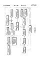
- FIGS. 23A-23D discloses the four systems shown in FIGS. 23A-23D for automatically driving a plurality of vehicles joined together as a platoon in a line behind the frontmost vehicle (referred to hereinafter as platoon leader) at a predetermined short distance from each other.
- the accelerators and brakes are controlled so as to drive the platoon leader 1 and the following vehicles 2 such that there is a predetermined distance between them.
- each of the vehicles 2 measures the inter-vehicle distance to a preceding vehicle, and the accelerator and brake are controlled based on this measured inter-vehicle distance so that a target inter-vehicle distance is maintained.
- a vehicle-to-vehicle communications system is also provided between the preceding and following vehicles.
- Each of the vehicles 2 then controls the accelerator and brake so as to maintain a target inter-vehicle distance based on the aforesaid measured value of the inter-vehicle distance and the vehicle communication data, e.g., vehicle speed, of the vehicle in front obtained by the vehicle-to-vehicle communications system.
- vehicle communication data e.g., vehicle speed
- a vehicle-to-vehicle communications system is provided between all the vehicles, communication data are provided by the platoon leader in addition to the preceding vehicle, and the accelerator and brake are controlled so as to maintain a target inter-vehicle distance based on this information and the measured inter-vehicle distance to the preceding vehicle.
- a control center 3 which controls all the vehicles is provided, each vehicle exchanges travel information with the preceding vehicle by inter-vehicle communication, and the accelerator and brake are controlled according to instructions and commands from the central control center 3.
- speed changes of the platoon leader 1 are progressively transmitted to the following vehicles 2. This means that speed changes of the platoon leader 1 are transmitted directly only to the vehicle 2 immediately following it, and as a result, when there are many vehicles in the line, a dilatational wave tends to be set up between the vehicles. This dilatational wave is especially serious when there are large differences in the performance and characteristics of the vehicles, hence the target value of the inter-vehicle distance has to be set large in order to take the dilatational wave into account.
- the vehicles are controlled using vehicle-to-vehicle communication data about the platoon leader 1 so inter-vehicle dilatational waves are suppressed to some extent, however this requires a complex communications system between all the vehicles in the platoon. Further, in the system of FIG. 23D, the whole platoon of vehicles is controlled while making inter-vehicle adjustments. It is then necessary to know the characteristics and performance of each vehicle, which makes it extremely difficult to design the control system including the control center 3.
- this invention provides a controller for controlling platooning of vehicles driving in a line, each of these vehicles having a travel speed varying mechanism for varying a travel speed of the vehicle.
- the controller comprises a mechanism for setting a virtual cell for each vehicle allowing a predetermined distance in front of and behind the vehicle, a first transmitting mechanism for transmitting a signal indicative of a virtual cell front end position of a frontmost vehicle in the group to the frontmost vehicle, a mechanism for calculating a virtual cell front end position of a (i+1)th vehicle from the frontmost vehicle, from a virtual cell front end position and a virtual cell of a ith vehicle, where i ranges from 1 to the total number of vehicles in said group, a second transmitting mechanism for transmitting a signal indicative of the virtual cell front end position of the (i+1)th vehicle to the (i+1)th vehicle, a mechanism for setting a target position of each vehicle in the virtual cell, a mechanism for detecting a real position of each vehicle in the virtual cell, and
- each vehicle is provided with the virtual cell setting mechanism, the target position setting mechanism, the real position detecting mechanism and the control mechanism, that each vehicle except the last vehicle in the group is provided with the calculating mechanism and the second transmitting mechanism, and that the first transmitting mechanism is provided independently of the group.
- the controller further comprises magnetic nails emitting magnetic pulses disposed at equidistant intervals on a road on which the group is traveling, and the position detecting mechanism comprises a magnetic sensor for detecting the magnetic pulses and a pulse counter for integrating the pulses.
- the position detecting mechanism comprises a GPS receiver.
- the first transmitting mechanism comprises a base station for specifying the virtual cell front end position of the frontmost vehicle with time and a transmitting device for transmitting the virtual cell front end position to the frontmost vehicle.
- the controller further comprises a mechanism for detecting a vehicle speed of each vehicle, and the virtual cell setting mechanism sets the virtual cell to a larger value the larger the vehicle speed.
- the controller further comprises a mechanism for detecting a weight of each vehicle, and the virtual cell setting mechanism sets the virtual cell to a larger value the larger the weight.
- the controller further comprises a mechanism for detecting a frictional coefficient between the tires of the vehicles and a road surface on which the vehicles are traveling, and the virtual cell setting mechanism sets the virtual cell to a larger value the smaller the frictional coefficient.
- the controller further comprises a mechanism for detecting a rainfall, and the virtual cell setting mechanism sets the virtual cell to a larger value when the rainfall is detected.
- the controller further comprises a mechanism for detecting a throttle opening of an engine driving each vehicle, a mechanism for detecting a travel speed of each vehicle, and a mechanism for determining whether or not each vehicle is traveling on a descending slope based on the throttle opening and travel speed of each vehicle, and that the virtual cell setting mechanism sets the virtual cell to a larger value when the vehicle is traveling on a descending slope.
- the controller further comprises a mechanism for detecting a gradient of a road surface on which the vehicles are traveling, and the virtual cell setting mechanism sets the virtual cell based on the road surface gradient.
- controller further comprises a mechanism for arbitrarily varying the virtual cell of each vehicle.
- the controller further comprises a mechanism for calculating a standard deviation of difference between the real position and the target position of each vehicle, and the virtual cell setting mechanism sets the virtual cell to a larger value the larger the standard deviation.
- FIG. 1 is a schematic diagram of a vehicle longitudinal spacing controller according to a first embodiment of this invention.
- FIG. 2 is a block diagram describing the functions of the controller.
- FIG. 3 is a flowchart describing a process for controlling the travel of a platoon leader executed by the controller.
- FIG. 4 is a flowchart describing a process for controlling the travel of a following vehicle executed by the controller.
- FIG. 5 is similar to FIG. 2, but showing a second embodiment of this invention.
- FIG. 6 is a flowchart describing a process for controlling the travel of the platoon leader according to the second embodiment.
- FIG. 7 is a flowchart describing a process for controlling the travel of the following vehicle according to the second embodiment.
- FIG. 8 is similar to FIG. 2, but showing a third embodiment of this invention.
- FIG. 9 is a flowchart describing a process for controlling the travel of the platoon leader according to the third embodiment.
- FIG. 10 is a flowchart describing a process for controlling the travel of the following vehicle according to the third embodiment.
- FIG. 11 is similar to FIG. 2, but showing a fourth embodiment of this invention.
- FIG. 12 is a flowchart describing a process for controlling the travel of the platoon leader according to the fourth embodiment.
- FIG. 13 is a flowchart describing a process for controlling the travel of the following vehicle according to the fourth embodiment.
- FIG. 14 is similar to FIG. 2, but showing a fifth embodiment of this invention.
- FIG. 15 is a flowchart describing a process for controlling the travel of the platoon leader according to the fifth embodiment.
- FIG. 16 is a flowchart describing a process for controlling the travel of the following vehicle according to the fifth embodiment.
- FIG. 17 is similar to FIG. 2, but showing a sixth embodiment.
- FIG. 18 is a flowchart describing a process for controlling the travel of the platoon leader according to the sixth embodiment.
- FIG. 19 is a flowchart describing a process for controlling the travel of the following vehicle according to the sixth embodiment.
- FIG. 20 is similar to FIG. 2, but showing a seventh embodiment of this invention.
- FIG. 21 is a flowchart describing a process for controlling the travel of the platoon leader according to the seventh embodiment.
- FIG. 22 is a flowchart describing a process for controlling the travel of the following vehicle according to the seventh embodiment.
- FIGS. 23A-23D are diagrams describing various prior art control systems.
- a group of vehicles 31 are running in a line behind a platoon leader 30 while a predetermined interval is maintained between them.
- a base station which guides the travel of the group of vehicles comprising a position indicating station 41, and a transmitting device 42 which may comprise for example a leak wave cable or the like that transmits a command signal output by the position indicating station along the road, is installed in the system.
- a predetermined virtual cell L i is preset for each vehicle. This virtual cell L i is separately set for each vehicle based on the vehicle length, vehicle performance and desired inter-vehicle distance.
- a relative position of the vehicle in the virtual cell L i i.e. a distance X i from the front end of the virtual cell P i to the reference position of the vehicle, is set for each vehicle.
- Each vehicle comprises an actuator 48 for varying an engine throttle opening and an actuator 49 for braking the vehicle so that the acceleration and deceleration of each vehicle are independently controlled as shown in FIG. 2.
- a vehicle-mounted receiver 43, virtual cell setter 51, vehicle-mounted transmitter 52, reference position memory 53, target position setter 44, magnetic sensor 46, pulse counter 47 and PID (Proportional, Integral and Differential) controller 50 are also provided.
- the target position setter 44, pulse counter 47, PID controller 50 and virtual cell setter 51 comprise for example microprocessors.
- a large number of magnetic nails 45 are embedded at equidistant intervals in the road surface over which the group of vehicles is traveling.
- the vehicle-mounted receiver 43 receives a command signal indicating a virtual cell front end position P 0 output by the position indicating station 41 via the transmitter 42. This command signal varies with time based on the target travel speed of the group of vehicles.
- the virtual cell setter 51 stores a virtual vehicle cell L 0 in an internal memory.
- a reference position X 0 of the vehicle in the virtual cell L 0 is stored in the reference position memory 53.
- the target position setter 44 calculates a target position P 0 +X 0 from the virtual cell front end position P 0 and the reference position X 0 .
- the magnetic sensor 46 detects magnetic pulses from the magnetic nails 45 on the road surface.
- the pulse counter 47 integrates these detected pulses.
- the PID controller 50 calculates a difference ⁇ 0 between the present position P 0 +Y 0 of the vehicle calculated from the integral value and the target position P 0 +X 0 , and controls the actuators 48, 49 such that ⁇ 0 is 0.
- the vehicle-mounted receiver 43 receives the virtual cell front end position P 1 from the platoon leader 30.
- the virtual cell setter 51 stores a virtual cell L 1 of the vehicle.
- a reference position X 1 of the vehicle in the virtual cell L 1 is stored in the reference position memory 53.
- the target position setter 44 calculates a target position P 1 +X 1 from the virtual cell front end position P 1 and the reference position X 1 .
- the PID controller 50 calculates a difference ⁇ 1 between the present position P 1 +Y 1 of the vehicle found from the magnetic sensor 46 and pulse counter 47, and the target position P 1 +X 1 , and controls the actuators 48, 49 such that ⁇ 1 is 0.
- the vehicle-mounted receiver 43 receives the virtual cell front end position P 2 from the first following vehicle 31.
- the virtual cell setter 51 stores a virtual cell L 2 of the vehicle.
- a reference position X 2 of the vehicle in the virtual cell L 2 is stored in the reference position memory 53.
- the target position setter 44 calculates a target position P 2 +X 2 from the virtual cell front end position P 2 and the reference position X 2 .
- the PID controller 50 calculates a difference ⁇ 2 between the present position P 2 +Y 2 of the vehicle found from the magnetic sensor 46 and pulse counter 47, and the target position P 2 +X 2 , and controls the actuators 48, 49 such that ⁇ 2 is 0.
- the third and subsequent following vehicles are controlled in the same way as the first and second following vehicles 31.
- the vehicle-mounted receiver 43 receives a virtual cell front end position P i from the immediately preceding vehicle (i is a vehicle number counted from the platoon leader as 0).
- the virtual cell setter 51 stores the virtual cell L i of the vehicle.
- the target position setter 44 calculates a target position P i +X i from the virtual cell front end position P i and the reference position X i stored in the reference position memory 53.
- the PID controller 50 calculates a difference ⁇ i between the present position P i +Y i of the vehicle found from the magnetic sensor 46 and pulse counter 47, and this target position P i +X i , and controls the actuators 48, 49 such that ⁇ i is 0.
- GPS Global Positioning System
- the GPS receiver may be a device used to obtain current position information in a car navigation system.
- step S1 the position indicating station 41 transmits the virtual cell front end position P 0 of the platoon leader, and in a step S2, the vehicle-mounted receiver 43 of the platoon leader receives this signal.
- the target position setter 44 calculates the target position P 0 +X 0 from the virtual cell front end position P 0 and reference position X 0 stored in the reference position memory 53.
- a step S4 the magnetic sensor 46 detects magnetic pulses from the magnetic nails 5, and the pulse counter 47 integrates the magnetic pulses so as to obtain the actual present position P 0 +Y 0 of the vehicle.
- the PID controller 50 calculates the difference ⁇ 0 between the target position P 0 +X 0 and the present position P 0 +Y 0 .
- the actuators 48, 49 adjust the engine throttle opening and brake according to the control signal.
- the target position setter 44 calculates the target position P i +X i from this virtual cell front end position P i and the reference position X i stored in the reference position memory 53.
- the magnetic sensor 46 detects magnetic pulses from the magnetic nails 5, and the pulse counter 47 integrates the magnetic pulses so as to obtain the actual present position P i +Y i of the vehicle.
- the PID controller 50 calculates the difference ⁇ 1 between the target position P i +X i and the present position P i +Y i .
- the actuators 48, 49 adjust the engine throttle opening and brake according to the control signal.
- the target position and present position of each vehicle are specified as relative positions in a virtual cell, and the travel speed is controlled such that the present position coincides with the target position for each vehicle.
- the virtual cell front end position P 0 of the platoon leader 30 moves, the virtual cell front end position P i of each of the following vehicles moves and each of the following vehicles moves together with its virtual cell.
- the virtual cell front end position is transmitted separately from the control process, and can therefore be transmitted rapidly without being affected by the time required to perform the control.
- the speed of the vehicle is unaffected by travel speed variations of the vehicles in front as in the case of the aforesaid conventional systems shown in FIGS. 23A, 23B wherein the distance to the vehicle in front is measured by a sensor. Consequently, dilatational waves between the vehicles are suppressed even when the group comprises a large number of vehicles, and the inter-vehicle distance may be set small. Still further, as the position of each vehicle can be controlled only by communication between the platoon leader 30 and the position indicating station 41, and by communication between preceding and following vehicles, design of the control system is easier than in the case of the aforesaid prior art systems shown in FIGS. 23C, 23D.
- FIGS. 5-7 show a second embodiment of this invention.
- the length of a virtual cell is varied according to the speed of a vehicle.
- the virtual cell of each vehicle is appropriately set from the overall length of the vehicle body and performance of the vehicle, but the braking distance varies according to changes in its motion characteristics. If the braking distance is S m!, "dead" time from when a braking command is issued until braking actually starts is t 0 s!, braking initial speed is v 0 m/s! and deceleration is ##EQU1##
- each vehicle is provided with a vehicle speed sensor 14 for detecting the speed of the vehicle as shown by FIG. 5.
- the virtual cell setter 51 corrects the virtual cell set value L 0 or L i to a larger value the higher the vehicle speed, for each vehicle.
- the position indicating station 41 may vary the amount of motion of the virtual cell front end position P 0 in unit time given to the platoon leader 30, i.e. the vehicle group speed of motion, according to the type of road, e.g. expressway or ordinary road. If the length of the virtual cell of each vehicle is varied according to the vehicle speed as in this embodiment, an optimum inter-vehicle distance is always maintained corresponding to the vehicle group speed.
- FIGS. 8-10 shows a third embodiment of this invention.
- each vehicle comprises a load sensor 15 for detecting the overall vehicle weight W as shown in FIG. 8.
- the virtual cell setter 51 corrects the virtual cell set value L 0 or L i to a length depending on the overall weight W of the vehicle, for each vehicle.
- the overall weight W of the vehicle largely varies according to whether the vehicle is full or empty. If the length of the virtual cell if each vehicle is corrected to be large when the vehicle is full and small when the vehicle is empty, an optimum inter-vehicle distance is always maintained corresponding to the overall vehicle weight.
- FIGS. 11-13 show a fourth embodiment of this invention.
- each vehicle is provided with a frictional coefficient estimator 16 which estimates the frictional coefficient between the tires and the road surface.
- the virtual cell setter 51 corrects the virtual cell set value L 0 or L i to a larger value the smaller the frictional coefficient for each vehicle.
- the frictional coefficient estimator 16 is described for example in the following publications:
- an optimum inter-vehicle distance is maintained even when the frictional coefficient between the tires and the road surface varies due for example to climatic changes.
- FIGS. 14-16 show a fifth embodiment of this invention.
- a rain sensor 20 which detects raindrops is provided instead of the frictional coefficient estimator 16 of the fourth embodiment.
- the rain sensor 20 on each vehicle determines whether or not it is raining, and the virtual cell setter 51 corrects the virtual cell set value L 0 or L i to a larger value when it is raining.
- an optimum inter-vehicle distance is maintained in rainy weather.
- FIGS. 17-19 show a sixth embodiment of this invention.
- each vehicle is provided with a throttle opening sensor 17 which detects the engine throttle opening, the vehicle speed sensor 14 which detects the vehicle speed, and a determining device 19 which determines whether or not the vehicle group is descending a slope from these detected values.
- the determining device 19 determines whether or not the vehicle is traveling down a slope from the throttle opening and vehicle speed for each vehicle, and the virtual cell setter 51 corrects the virtual cell set value L 0 or L i to a larger value on a descending slope.
- Each vehicle may also be provided with a slope sensor which detects the gradient of the road surface, the virtual cell setter 51 correcting the length of the virtual cell to a smaller value when the vehicle is traveling on an ascending slope and to a larger value when the vehicle is traveling on a descending slope, according to the detected value of the slope sensor.
- the braking distance On a descending slope the braking distance is longer, however by correcting the length of the virtual cell to a larger value on a descent in this way, an optimum inter-vehicle distance corresponding to the increase of braking distance is maintained.
- Each of the aforesaid second to sixth embodiments has the effect of increasing the safety of the group of vehicles even when applied alone. It is however desirable to combine them to calculate the required braking distance for each vehicle from the aforesaid equation (1), and correct the set value of the virtual cell accordingly.
- a virtual cell setting means corrects the length of the virtual cell according to an adjustment value of the adjusting device, non-specific variations of conditions which may have an effect on the braking distance can be compensated as desired.
- the PID controller 50 controls the present position P i +Y i of each vehicle so as to make it coincide with its present target position P i +X i , however some scatter in the control precision may occur for each vehicle.
- FIGS. 20-22 show a seventh embodiment related to correction for this scattering.
- a control precision detector 21 which detects the control precision of a vehicle from the difference ⁇ i between its present position and its target position, is provided as shown in FIG. 20.
- the virtual cell setter 51 corrects the value L 0 or L i of the virtual cell of the vehicle to a length depending on the control precision. More specifically, the control precision detector 21 calculates the average value of the difference ⁇ i in unit time, i.e. the standard deviation, and the virtual cell setter 51 corrects the virtual cell set value L 0 or L i to a larger value, the larger the standard deviation.
- scatter may occur in the travel control precision of each vehicle depending on the precision of each sensor, however if the virtual cell set value is corrected for each vehicle based on the standard deviation as according to this embodiment, the inter-vehicle distance required to absorb control errors is maintained, and the length of the whole vehicle group may be reduced.
Abstract
Description
Claims (13)
Applications Claiming Priority (2)
| Application Number | Priority Date | Filing Date | Title |
|---|---|---|---|
| JP05182996A JP3633707B2 (en) | 1996-03-08 | 1996-03-08 | Vehicle group running control device |
| JP8-051829 | 1996-03-08 |
Publications (1)
| Publication Number | Publication Date |
|---|---|
| US5777451A true US5777451A (en) | 1998-07-07 |
Family
ID=12897772
Family Applications (1)
| Application Number | Title | Priority Date | Filing Date |
|---|---|---|---|
| US08/719,676 Expired - Fee Related US5777451A (en) | 1996-03-08 | 1996-09-25 | Vehicle longitudinal spacing controller |
Country Status (4)
| Country | Link |
|---|---|
| US (1) | US5777451A (en) |
| JP (1) | JP3633707B2 (en) |
| CN (1) | CN1082463C (en) |
| HK (1) | HK1005235A1 (en) |
Cited By (93)
| Publication number | Priority date | Publication date | Assignee | Title |
|---|---|---|---|---|
| US6032097A (en) * | 1996-11-27 | 2000-02-29 | Honda Giken Kogyo Kabushiki Kaisha | Vehicle platoon control system |
| WO1999067117A3 (en) * | 1998-06-23 | 2000-03-02 | Siemens Ag | Method for reducing data in railway operation |
| US6067031A (en) * | 1997-12-18 | 2000-05-23 | Trimble Navigation Limited | Dynamic monitoring of vehicle separation |
| US6138062A (en) * | 1996-07-15 | 2000-10-24 | Toyota Jidoshia Kabushiki Kaisha | Automatic travel controlling device |
| US6138064A (en) * | 1996-10-02 | 2000-10-24 | Mitsubishi Heavy Industries, Ltd. | Method of automatically controlling traveling of vehicle |
| US6167331A (en) * | 1997-08-21 | 2000-12-26 | Mitsubishi Heavy Industries, Ltd. | Method and system for controlling a plurality of vehicles as a group unit |
| WO2002023504A1 (en) * | 2000-09-15 | 2002-03-21 | K.K. Holding Ag | Monitoring and guiding of the traffic flow in road tunnels, on bridges and other restricted stretches |
| EP0958987A3 (en) * | 1998-05-20 | 2002-05-22 | Alcatel | Method for operating railway vehicles as well as train control centre and vehicle mounted apparatus therefor |
| US6449554B2 (en) * | 2000-01-25 | 2002-09-10 | Yasuyuki Suzuki | Travel speed controller for electrically powered light weight vehicle, and electrically powered light weight vehicle |
| US6498981B1 (en) * | 1999-12-30 | 2002-12-24 | Honeywell International Inc. | System for sequencing traffic |
| US6634225B1 (en) * | 1999-06-18 | 2003-10-21 | Valeo Auto-Electric Wischer Und Motoren Gmbh | Rain sensor using low harmonic content signals |
| EP1369332A2 (en) * | 2002-06-04 | 2003-12-10 | Bombardier Transportation (Technology) GmbH | Automated system and method for manipulation of vehicles in a railway system |
| US20040068393A1 (en) * | 2000-12-11 | 2004-04-08 | Lawrence Malcolm G. | Highway vehicular traffic flow control |
| WO2004039650A1 (en) * | 2002-10-30 | 2004-05-13 | Dürr Automotion Gmbh | Track-guided transport system and method for controlling cars of a track-guided transport system |
| EP1444604A2 (en) * | 2001-10-22 | 2004-08-11 | Cascade Engineering, Inc. | Individual transport control and communication system |
| US7000587B1 (en) | 2004-11-24 | 2006-02-21 | Detroit Diesel Corporation | System for changing a selected engine function based on sensed weather conditions |
| US20060161341A1 (en) * | 2005-01-14 | 2006-07-20 | Alcatel | Navigation service |
| US20060229803A1 (en) * | 2005-04-11 | 2006-10-12 | Murata Kikai Kabushiki Kaisha | Guided vehicle system |
| US20060259211A1 (en) * | 2003-10-16 | 2006-11-16 | Duerr Systems Gmbh | Track-guided transport system |
| US20070150134A1 (en) * | 2005-12-26 | 2007-06-28 | Aisin Aw Co., Ltd | Driving support systems, methods, and programs |
| US20070198140A1 (en) * | 2006-02-21 | 2007-08-23 | Mudalige Upali P | Inter vehicular ad hoc routing protocol and communication system |
| US20070232448A1 (en) * | 2003-10-25 | 2007-10-04 | Daimler Chrysler Ag | Method and Device for Controlling Distance |
| US20080015745A1 (en) * | 2004-09-23 | 2008-01-17 | Gaegauf Benedikt J | Individual transport control and communication system |
| US20100060482A1 (en) * | 2008-09-08 | 2010-03-11 | International Business Machines Corporation | Automated traffic synchronization |
| US20100299044A1 (en) * | 2007-11-26 | 2010-11-25 | Equos Research Co., Ltd. | Vehicle control device |
| US20110015807A1 (en) * | 2009-07-15 | 2011-01-20 | General Electric Company | System and method for vehicle performance control |
| EP2285639A2 (en) * | 2008-05-26 | 2011-02-23 | Posco | Method for platooning of vehicles in an automated vehicle system |
| US20110106391A1 (en) * | 2009-03-04 | 2011-05-05 | Toyota Jidosha Kabushiki Kaisha | Follow-up run control device |
| DE102009059170A1 (en) * | 2009-12-16 | 2011-06-22 | Maurer Söhne GmbH & Co. KG, 80807 | Electrical coupling |
| US20110270514A1 (en) * | 2009-01-20 | 2011-11-03 | Toyota Jidosha Kabushiki Kaisha | Row-running control system and vehicle |
| US20110288754A1 (en) * | 2009-01-23 | 2011-11-24 | Toyota Jidosha Kabushiki Kaisha | Vehicle group control method and vehicle |
| US20120154154A1 (en) * | 2000-12-26 | 2012-06-21 | Robert Ernest Troxler | Position and proximity detection systems and methods |
| US8369967B2 (en) | 1999-02-01 | 2013-02-05 | Hoffberg Steven M | Alarm system controller and a method for controlling an alarm system |
| US20130060456A1 (en) * | 2011-09-02 | 2013-03-07 | Peyman Pourparhizkar | Synchronizing car movements in road to reduce traffic |
| US20130096773A1 (en) * | 2010-04-07 | 2013-04-18 | Tomoyuki Doi | Vehicle driving-support apparatus |
| US20130166150A1 (en) * | 2011-12-26 | 2013-06-27 | Hyundai Motor Company | System and method for controlling inter-vehicle distance using side and rear sensor |
| WO2013147684A1 (en) * | 2012-03-29 | 2013-10-03 | Scania Cv Ab | Method and system for spacing adjustment in a moving vehicle train |
| US20130268298A1 (en) * | 2012-04-05 | 2013-10-10 | Tanya Elkins | Vin based insurance claim system |
| US8620517B2 (en) | 2012-02-21 | 2013-12-31 | Toyota Mototr Engineering & Manufacturing North America, Inc. | Vehicular platooning using distributed receding horizon control |
| WO2014003630A1 (en) * | 2012-06-14 | 2014-01-03 | Scania Cv Ab | System and method for regulating of vehicle pertaining to a vehicle train |
| DE102012212339A1 (en) * | 2012-07-13 | 2014-01-16 | Siemens Aktiengesellschaft | Method for platooning of vehicles on road, involves determining minimum power consumption of grouping, and sending response to request to participate in grouping by transmission of data required for grouping to vehicles of grouping |
| US8682605B2 (en) | 2002-10-11 | 2014-03-25 | Troxler Electronic Laboratories, Inc. | Paving related measuring device incorporating a computer device and communication element therebetween and associated method |
| US20140100734A1 (en) * | 2012-10-04 | 2014-04-10 | Denso Corporation | Convoy travel apparatus |
| WO2014148991A1 (en) * | 2013-03-19 | 2014-09-25 | Scania Cv Ab | Friction monitoring system for a vehicle and a method pertaining to such a system |
| US8892495B2 (en) | 1991-12-23 | 2014-11-18 | Blanding Hovenweep, Llc | Adaptive pattern recognition based controller apparatus and method and human-interface therefore |
| US8965677B2 (en) | 1998-10-22 | 2015-02-24 | Intelligent Technologies International, Inc. | Intra-vehicle information conveyance system and method |
| US8983771B2 (en) | 1997-10-22 | 2015-03-17 | Intelligent Technologies International, Inc. | Inter-vehicle information conveyance system and method |
| WO2016013996A1 (en) * | 2014-07-25 | 2016-01-28 | Okan Üni̇versitesi̇ | A close range vehicle following system which can provide vehicle distances and course by using various variables. |
| US9296411B2 (en) | 2014-08-26 | 2016-03-29 | Cnh Industrial America Llc | Method and system for controlling a vehicle to a moving point |
| US20170032677A1 (en) * | 2015-07-30 | 2017-02-02 | Hyundai Motor Company | Vehicle, and Apparatus and Method for Controlling Vehicle |
| US9632507B1 (en) * | 2016-01-29 | 2017-04-25 | Meritor Wabco Vehicle Control Systems | System and method for adjusting vehicle platoon distances based on predicted external perturbations |
| US20170115666A1 (en) * | 2014-08-04 | 2017-04-27 | Cummins, Inc. | Apparatus and method for grouping vehicles for cooperative driving |
| US20180072157A1 (en) * | 2005-11-17 | 2018-03-15 | Invently Automotive Inc. | Managing spacing between a group of vehicles |
| US10007271B2 (en) * | 2015-12-11 | 2018-06-26 | Avishtech, Llc | Autonomous vehicle towing system and method |
| US20180190119A1 (en) * | 2016-12-30 | 2018-07-05 | Bendix Commercial Vehicle Systems Llc | Detection of extra-platoon vehicle intermediate or adjacent to platoon member vehicles |
| US20180210463A1 (en) * | 2013-03-15 | 2018-07-26 | Peloton Technology, Inc. | System and method for implementing pre-cognition braking and/or avoiding or mitigation risks among platooning vehicles |
| US20180253976A1 (en) * | 2015-09-17 | 2018-09-06 | Telefonaktiebolaget Lm Ericsson (Publ) | Communication Device, First Radio Node, Second Radio Node, and Methods Therein, for Determining Whether to Allow a First Vehicle to Overtake a Vehicle Platoon |
| US10086299B2 (en) | 2014-08-15 | 2018-10-02 | Universal City Studios Llc | System and method for modular ride vehicles |
| US10152064B2 (en) | 2016-08-22 | 2018-12-11 | Peloton Technology, Inc. | Applications for using mass estimations for vehicles |
| US20190096265A1 (en) * | 2017-09-27 | 2019-03-28 | Hyundai Mobis Co., Ltd. | Platooning control apparatus and method |
| US10254764B2 (en) | 2016-05-31 | 2019-04-09 | Peloton Technology, Inc. | Platoon controller state machine |
| US20190147745A1 (en) * | 2017-11-13 | 2019-05-16 | Hyundai Motor Company | Apparatus and method for controlling platooning of vehicles |
| SE1751630A1 (en) * | 2017-12-22 | 2019-06-23 | Scania Cv Ab | Method and a control arrangement for controlling vehicle operation comprising axle load control of at least one vehicle during vehicle operation |
| US10332403B2 (en) * | 2017-01-04 | 2019-06-25 | Honda Motor Co., Ltd. | System and method for vehicle congestion estimation |
| WO2019122695A1 (en) * | 2017-12-22 | 2019-06-27 | Compagnie Generale Des Etablissements Michelin | Method for managing a platoon of trucks on the basis of information relating to the tyres with which the trucks of said platoon are equipped |
| US10339815B1 (en) * | 2017-12-29 | 2019-07-02 | Hyundai Motor Company | Apparatus and method for controlling lamp of platooning vehicle |
| US10361802B1 (en) | 1999-02-01 | 2019-07-23 | Blanding Hovenweep, Llc | Adaptive pattern recognition based control system and method |
| US10369998B2 (en) | 2016-08-22 | 2019-08-06 | Peloton Technology, Inc. | Dynamic gap control for automated driving |
| US10449962B2 (en) | 2016-06-23 | 2019-10-22 | Honda Motor Co., Ltd. | System and method for vehicle control using vehicular communication |
| US10471953B1 (en) * | 2017-02-21 | 2019-11-12 | Zoox, Inc. | Occupant aware braking system |
| US10515553B2 (en) * | 2015-02-26 | 2019-12-24 | Volvo Truck Corporation | Method of controlling inter-vehicle gap(s) |
| US10514706B2 (en) | 2011-07-06 | 2019-12-24 | Peloton Technology, Inc. | Gap measurement for vehicle convoying |
| US10520581B2 (en) | 2011-07-06 | 2019-12-31 | Peloton Technology, Inc. | Sensor fusion for autonomous or partially autonomous vehicle control |
| US10520952B1 (en) | 2011-07-06 | 2019-12-31 | Peloton Technology, Inc. | Devices, systems, and methods for transmitting vehicle data |
| US10625742B2 (en) | 2016-06-23 | 2020-04-21 | Honda Motor Co., Ltd. | System and method for vehicle control in tailgating situations |
| US10703262B1 (en) * | 2019-04-10 | 2020-07-07 | Hyundai Motor Company | Apparatus and method for outputting platooning information in vehicle |
| US10712748B2 (en) * | 2015-08-26 | 2020-07-14 | Peloton Technology, Inc. | Devices, systems, and methods for generating travel forecasts for vehicle pairing |
| US10732645B2 (en) | 2011-07-06 | 2020-08-04 | Peloton Technology, Inc. | Methods and systems for semi-autonomous vehicular convoys |
| US10737667B2 (en) | 2016-06-23 | 2020-08-11 | Honda Motor Co., Ltd. | System and method for vehicle control in tailgating situations |
| US10762791B2 (en) | 2018-10-29 | 2020-09-01 | Peloton Technology, Inc. | Systems and methods for managing communications between vehicles |
| CN111640324A (en) * | 2019-03-01 | 2020-09-08 | 丰田自动车株式会社 | Operation control device and vehicle |
| US20200402409A1 (en) * | 2018-03-28 | 2020-12-24 | Kabushiki Kaisha Toshiba | Platooning operation system and platooning operation method |
| US10899323B2 (en) | 2018-07-08 | 2021-01-26 | Peloton Technology, Inc. | Devices, systems, and methods for vehicle braking |
| US11092687B2 (en) * | 2016-09-12 | 2021-08-17 | Sew-Eurodrive Gmbh & Co. Kg | Method and system for position capture |
| US20210268902A1 (en) * | 2016-06-28 | 2021-09-02 | Panasonic Intellectual Property Management Co., Ltd. | Driving assistance apparatus and driving assistance method |
| US11161503B2 (en) | 2016-06-23 | 2021-11-02 | Honda Motor Co., Ltd. | Vehicular communications network and methods of use and manufacture thereof |
| US11294396B2 (en) | 2013-03-15 | 2022-04-05 | Peloton Technology, Inc. | System and method for implementing pre-cognition braking and/or avoiding or mitigation risks among platooning vehicles |
| US11334092B2 (en) | 2011-07-06 | 2022-05-17 | Peloton Technology, Inc. | Devices, systems, and methods for transmitting vehicle data |
| US11338813B2 (en) | 2016-06-23 | 2022-05-24 | Honda Motor Co., Ltd. | System and method for merge assist using vehicular communication |
| US11430338B2 (en) | 2017-08-03 | 2022-08-30 | Ford Global Technologies, Llc | Intersection crossing control |
| US11427196B2 (en) | 2019-04-15 | 2022-08-30 | Peloton Technology, Inc. | Systems and methods for managing tractor-trailers |
| US11657718B2 (en) * | 2017-05-15 | 2023-05-23 | Huawei Cloud Computing Technologies Co., Ltd. | Method for controlling vehicle platoon, device, and internet of vehicles system |
| EP4019354A4 (en) * | 2019-09-13 | 2023-10-04 | Daimler Truck AG | Platooning control apparatus |
Families Citing this family (20)
| Publication number | Priority date | Publication date | Assignee | Title |
|---|---|---|---|---|
| DE19750942A1 (en) * | 1997-11-17 | 1999-05-20 | Delphi 2 Creative Tech Gmbh | Signaling system of traffic events |
| FI120191B (en) * | 2005-10-03 | 2009-07-31 | Sandvik Tamrock Oy | A method for driving mining vehicles in a mine and a transportation system |
| JP4552998B2 (en) * | 2007-11-19 | 2010-09-29 | 村田機械株式会社 | Transport vehicle system |
| WO2010131324A1 (en) * | 2009-05-11 | 2010-11-18 | トヨタ自動車株式会社 | Vehicle group control method and vehicle |
| JP5058243B2 (en) | 2009-12-14 | 2012-10-24 | アイシン・エィ・ダブリュ株式会社 | Vehicle guidance device, vehicle guidance method, and vehicle guidance program |
| CN102390409A (en) * | 2011-09-09 | 2012-03-28 | 俞钟晓 | Motor train intuitively findable for back train in front of safety interval |
| KR101727329B1 (en) | 2011-10-19 | 2017-04-17 | 엘에스산전 주식회사 | An apparatus and method for mesuring velocity of train |
| CN102756748A (en) * | 2012-07-31 | 2012-10-31 | 上海中科高等研究院 | Train anticollision system on basis of sound wave communication and anticollision method thereof |
| CN103395419B (en) * | 2013-08-22 | 2016-02-24 | 贵州大学 | Based on vehicle platoon drive-control system and the control method thereof of safe spacing strategy |
| JP6285303B2 (en) * | 2014-07-11 | 2018-02-28 | 株式会社デンソー | Vehicle control device |
| JP6478027B2 (en) * | 2015-02-13 | 2019-03-06 | アイシン・エィ・ダブリュ株式会社 | Convoy travel management device and convoy travel management program |
| KR101736104B1 (en) * | 2015-10-28 | 2017-05-16 | 현대자동차주식회사 | Vehicle and controlling method for the vehicle |
| CN105279958B (en) * | 2015-11-13 | 2018-02-16 | 奇瑞汽车股份有限公司 | fleet management system and method |
| CN106054902A (en) * | 2016-08-19 | 2016-10-26 | 郑晓辉 | Mine unmanned transportation fleet control system |
| CN106774330B (en) * | 2016-12-29 | 2021-01-22 | 山东中天宇信信息技术有限公司 | Planting track cloud management system and method |
| US10372123B2 (en) * | 2016-12-30 | 2019-08-06 | Bendix Commercial Vehicle Systems Llc | “V” shaped and wide platoon formations |
| CN109307861B (en) * | 2017-07-28 | 2021-09-03 | 比亚迪股份有限公司 | Vehicle, vehicle positioning method and vehicle-mounted equipment |
| CN110047271B (en) * | 2019-05-20 | 2020-08-25 | 长安大学 | Motorcade management system and motorcade management method based on same |
| CN110525435B (en) * | 2019-07-23 | 2021-09-17 | 北京汽车集团有限公司 | Method and device for acquiring vehicle distance, storage medium and vehicle |
| CN112622902A (en) * | 2021-01-15 | 2021-04-09 | 江苏理工学院 | Self-adaptive cruise control system based on brake-by-wire |
Citations (14)
| Publication number | Priority date | Publication date | Assignee | Title |
|---|---|---|---|---|
| US3708668A (en) * | 1971-06-01 | 1973-01-02 | J Tilley | Vehicle optical guidance system |
| US4202048A (en) * | 1972-11-05 | 1980-05-06 | United Geophysical Corporation | Seismic prospecting system |
| US4473787A (en) * | 1980-11-14 | 1984-09-25 | Inventio Ag | Equipment for maintaining the spacing of track-bound vehicles |
| US4477184A (en) * | 1979-01-19 | 1984-10-16 | Nissan Motor Company, Limited | Obstacle detection system for use in vehicles |
| US4783618A (en) * | 1982-12-27 | 1988-11-08 | Acme Visible Records, Inc | Apparatus and method for controlling apparatus including a plurality of guided units |
| US5081703A (en) * | 1990-06-27 | 1992-01-14 | Pactel Corporation | Satellite mobile communication system for rural service areas |
| US5091855A (en) * | 1989-04-17 | 1992-02-25 | Kabushiki Kaisha Toyoda Jidoshokki Seisakusho | Operation control system for automated guide vehicles |
| US5267173A (en) * | 1990-10-23 | 1993-11-30 | Daifuku Co., Ltd. | Carriage running control system |
| US5278892A (en) * | 1991-07-09 | 1994-01-11 | At&T Bell Laboratories | Mobile telephone system call processing arrangement |
| US5400864A (en) * | 1992-01-14 | 1995-03-28 | Robert Bosch Gmbh | Method and apparatus for controlling the speed of a vehicle and its spacing from a preceding vehicle |
| US5473233A (en) * | 1994-03-08 | 1995-12-05 | Stull; Mark A. | Electromagnetically propelled high-speed high-capacity transportation system for short-distance travel in urban and suburban areas |
| US5548806A (en) * | 1993-01-25 | 1996-08-20 | Kokusai Denshin Denwa Co., Ltd. | Mobile communication system having a cell structure constituted by integrating macro cells and micro cells |
| US5548816A (en) * | 1993-11-16 | 1996-08-20 | Astronet | Method and system for locating mobile units in a cellular telephone system by use of virtual location areas |
| US5621514A (en) * | 1995-01-05 | 1997-04-15 | Hughes Electronics | Random pulse burst range-resolved doppler laser radar |
Family Cites Families (7)
| Publication number | Priority date | Publication date | Assignee | Title |
|---|---|---|---|---|
| JPH0554298A (en) * | 1991-08-29 | 1993-03-05 | Omron Corp | Collision prevention device |
| JP2995970B2 (en) * | 1991-12-18 | 1999-12-27 | トヨタ自動車株式会社 | Travel control device for vehicles |
| JPH07115405A (en) * | 1993-10-15 | 1995-05-02 | Oki Electric Ind Co Ltd | Method for communication between vehicles |
| JPH07200991A (en) * | 1993-11-30 | 1995-08-04 | Sconick Joseph | Cooperative operation system of two or more vehicles |
| JPH0855300A (en) * | 1994-08-08 | 1996-02-27 | Mitsubishi Electric Corp | Controller of vehicle group travel system |
| JP3191621B2 (en) * | 1995-03-14 | 2001-07-23 | トヨタ自動車株式会社 | Vehicle travel guidance system |
| JP3237451B2 (en) * | 1995-04-10 | 2001-12-10 | 三菱自動車工業株式会社 | Automatic following system |
-
1996
- 1996-03-08 JP JP05182996A patent/JP3633707B2/en not_active Expired - Lifetime
- 1996-09-25 US US08/719,676 patent/US5777451A/en not_active Expired - Fee Related
- 1996-09-28 CN CN96122820A patent/CN1082463C/en not_active Expired - Lifetime
-
1998
- 1998-05-19 HK HK98104311A patent/HK1005235A1/en not_active IP Right Cessation
Patent Citations (14)
| Publication number | Priority date | Publication date | Assignee | Title |
|---|---|---|---|---|
| US3708668A (en) * | 1971-06-01 | 1973-01-02 | J Tilley | Vehicle optical guidance system |
| US4202048A (en) * | 1972-11-05 | 1980-05-06 | United Geophysical Corporation | Seismic prospecting system |
| US4477184A (en) * | 1979-01-19 | 1984-10-16 | Nissan Motor Company, Limited | Obstacle detection system for use in vehicles |
| US4473787A (en) * | 1980-11-14 | 1984-09-25 | Inventio Ag | Equipment for maintaining the spacing of track-bound vehicles |
| US4783618A (en) * | 1982-12-27 | 1988-11-08 | Acme Visible Records, Inc | Apparatus and method for controlling apparatus including a plurality of guided units |
| US5091855A (en) * | 1989-04-17 | 1992-02-25 | Kabushiki Kaisha Toyoda Jidoshokki Seisakusho | Operation control system for automated guide vehicles |
| US5081703A (en) * | 1990-06-27 | 1992-01-14 | Pactel Corporation | Satellite mobile communication system for rural service areas |
| US5267173A (en) * | 1990-10-23 | 1993-11-30 | Daifuku Co., Ltd. | Carriage running control system |
| US5278892A (en) * | 1991-07-09 | 1994-01-11 | At&T Bell Laboratories | Mobile telephone system call processing arrangement |
| US5400864A (en) * | 1992-01-14 | 1995-03-28 | Robert Bosch Gmbh | Method and apparatus for controlling the speed of a vehicle and its spacing from a preceding vehicle |
| US5548806A (en) * | 1993-01-25 | 1996-08-20 | Kokusai Denshin Denwa Co., Ltd. | Mobile communication system having a cell structure constituted by integrating macro cells and micro cells |
| US5548816A (en) * | 1993-11-16 | 1996-08-20 | Astronet | Method and system for locating mobile units in a cellular telephone system by use of virtual location areas |
| US5473233A (en) * | 1994-03-08 | 1995-12-05 | Stull; Mark A. | Electromagnetically propelled high-speed high-capacity transportation system for short-distance travel in urban and suburban areas |
| US5621514A (en) * | 1995-01-05 | 1997-04-15 | Hughes Electronics | Random pulse burst range-resolved doppler laser radar |
Cited By (157)
| Publication number | Priority date | Publication date | Assignee | Title |
|---|---|---|---|---|
| US8892495B2 (en) | 1991-12-23 | 2014-11-18 | Blanding Hovenweep, Llc | Adaptive pattern recognition based controller apparatus and method and human-interface therefore |
| US6138062A (en) * | 1996-07-15 | 2000-10-24 | Toyota Jidoshia Kabushiki Kaisha | Automatic travel controlling device |
| US6138064A (en) * | 1996-10-02 | 2000-10-24 | Mitsubishi Heavy Industries, Ltd. | Method of automatically controlling traveling of vehicle |
| US6032097A (en) * | 1996-11-27 | 2000-02-29 | Honda Giken Kogyo Kabushiki Kaisha | Vehicle platoon control system |
| US6167331A (en) * | 1997-08-21 | 2000-12-26 | Mitsubishi Heavy Industries, Ltd. | Method and system for controlling a plurality of vehicles as a group unit |
| US8983771B2 (en) | 1997-10-22 | 2015-03-17 | Intelligent Technologies International, Inc. | Inter-vehicle information conveyance system and method |
| US6067031A (en) * | 1997-12-18 | 2000-05-23 | Trimble Navigation Limited | Dynamic monitoring of vehicle separation |
| EP0958987A3 (en) * | 1998-05-20 | 2002-05-22 | Alcatel | Method for operating railway vehicles as well as train control centre and vehicle mounted apparatus therefor |
| US7578485B1 (en) | 1998-06-23 | 2009-08-25 | Siemens Aktiengesellschaft | Method for reducing data in railway operation |
| WO1999067117A3 (en) * | 1998-06-23 | 2000-03-02 | Siemens Ag | Method for reducing data in railway operation |
| US8965677B2 (en) | 1998-10-22 | 2015-02-24 | Intelligent Technologies International, Inc. | Intra-vehicle information conveyance system and method |
| US8369967B2 (en) | 1999-02-01 | 2013-02-05 | Hoffberg Steven M | Alarm system controller and a method for controlling an alarm system |
| US9535563B2 (en) | 1999-02-01 | 2017-01-03 | Blanding Hovenweep, Llc | Internet appliance system and method |
| US10361802B1 (en) | 1999-02-01 | 2019-07-23 | Blanding Hovenweep, Llc | Adaptive pattern recognition based control system and method |
| US6634225B1 (en) * | 1999-06-18 | 2003-10-21 | Valeo Auto-Electric Wischer Und Motoren Gmbh | Rain sensor using low harmonic content signals |
| US6498981B1 (en) * | 1999-12-30 | 2002-12-24 | Honeywell International Inc. | System for sequencing traffic |
| US6449554B2 (en) * | 2000-01-25 | 2002-09-10 | Yasuyuki Suzuki | Travel speed controller for electrically powered light weight vehicle, and electrically powered light weight vehicle |
| WO2002023504A1 (en) * | 2000-09-15 | 2002-03-21 | K.K. Holding Ag | Monitoring and guiding of the traffic flow in road tunnels, on bridges and other restricted stretches |
| US7002486B2 (en) * | 2000-12-11 | 2006-02-21 | Lawrence Malcolm G | Highway vehicular traffic flow control |
| US20040068393A1 (en) * | 2000-12-11 | 2004-04-08 | Lawrence Malcolm G. | Highway vehicular traffic flow control |
| US10109174B2 (en) | 2000-12-26 | 2018-10-23 | Robert Ernest Troxler | Position and proximity detection systems and methods |
| US20120154154A1 (en) * | 2000-12-26 | 2012-06-21 | Robert Ernest Troxler | Position and proximity detection systems and methods |
| US8624723B2 (en) * | 2000-12-26 | 2014-01-07 | Robert Ernest Troxler | Position and proximity detection systems and methods |
| US20050090981A1 (en) * | 2001-10-22 | 2005-04-28 | Gaegauf Benedikt J. | Individual transport control and communication system |
| EP1444604A2 (en) * | 2001-10-22 | 2004-08-11 | Cascade Engineering, Inc. | Individual transport control and communication system |
| US7286934B2 (en) * | 2001-10-22 | 2007-10-23 | Cascade Engineering, Inc. | Individual transport control and communication system |
| EP1444604A4 (en) * | 2001-10-22 | 2008-09-24 | Cascade Eng Inc | Individual transport control and communication system |
| EP1369332A3 (en) * | 2002-06-04 | 2004-01-07 | Bombardier Transportation (Technology) GmbH | Automated system and method for manipulation of vehicles in a railway system |
| EP1369332A2 (en) * | 2002-06-04 | 2003-12-10 | Bombardier Transportation (Technology) GmbH | Automated system and method for manipulation of vehicles in a railway system |
| US8682605B2 (en) | 2002-10-11 | 2014-03-25 | Troxler Electronic Laboratories, Inc. | Paving related measuring device incorporating a computer device and communication element therebetween and associated method |
| US20060255210A1 (en) * | 2002-10-30 | 2006-11-16 | Duerr Automotion Gmbh | Track-guided transport system and method for controlling cars of a track-guided transport system |
| KR100739442B1 (en) | 2002-10-30 | 2007-07-13 | 뒤르 오토모션 게엠베하 | Track-guided transport system and method for controlling cars of a track-guided transport system |
| WO2004039650A1 (en) * | 2002-10-30 | 2004-05-13 | Dürr Automotion Gmbh | Track-guided transport system and method for controlling cars of a track-guided transport system |
| US7182298B2 (en) | 2002-10-30 | 2007-02-27 | Duerr Systems Gmbh | Track-guided transport system and method for controlling cars of a track-guided transport system |
| US20050247231A1 (en) * | 2002-10-30 | 2005-11-10 | Durr Automotion Gmbh | Track-guided transport system and method for controlling cars of a track-guided transport system |
| US20060259211A1 (en) * | 2003-10-16 | 2006-11-16 | Duerr Systems Gmbh | Track-guided transport system |
| US20070232448A1 (en) * | 2003-10-25 | 2007-10-04 | Daimler Chrysler Ag | Method and Device for Controlling Distance |
| US20080015745A1 (en) * | 2004-09-23 | 2008-01-17 | Gaegauf Benedikt J | Individual transport control and communication system |
| US7561948B2 (en) | 2004-09-23 | 2009-07-14 | Cascade Engineering, Inc. | Individual transport control and communication system |
| US7000587B1 (en) | 2004-11-24 | 2006-02-21 | Detroit Diesel Corporation | System for changing a selected engine function based on sensed weather conditions |
| US7613563B2 (en) * | 2005-01-14 | 2009-11-03 | Alcatel | Navigation service |
| US20060161341A1 (en) * | 2005-01-14 | 2006-07-20 | Alcatel | Navigation service |
| US20060229803A1 (en) * | 2005-04-11 | 2006-10-12 | Murata Kikai Kabushiki Kaisha | Guided vehicle system |
| US20180072157A1 (en) * | 2005-11-17 | 2018-03-15 | Invently Automotive Inc. | Managing spacing between a group of vehicles |
| US10882416B2 (en) * | 2005-11-17 | 2021-01-05 | Invently Automotive Inc. | Managing spacing between a group of vehicles |
| US20070150134A1 (en) * | 2005-12-26 | 2007-06-28 | Aisin Aw Co., Ltd | Driving support systems, methods, and programs |
| US20070198140A1 (en) * | 2006-02-21 | 2007-08-23 | Mudalige Upali P | Inter vehicular ad hoc routing protocol and communication system |
| US20100299044A1 (en) * | 2007-11-26 | 2010-11-25 | Equos Research Co., Ltd. | Vehicle control device |
| US8352147B2 (en) * | 2007-11-26 | 2013-01-08 | Equos Research Co., Ltd. | Vehicle control device |
| EP2285639A2 (en) * | 2008-05-26 | 2011-02-23 | Posco | Method for platooning of vehicles in an automated vehicle system |
| KR101463250B1 (en) * | 2008-05-26 | 2014-11-18 | 주식회사 포스코 | Method for platooning of vehicles in an automated vehicle system |
| EP2285639A4 (en) * | 2008-05-26 | 2012-02-08 | Posco | Method for platooning of vehicles in an automated vehicle system |
| US20100060482A1 (en) * | 2008-09-08 | 2010-03-11 | International Business Machines Corporation | Automated traffic synchronization |
| US8344906B2 (en) * | 2008-09-08 | 2013-01-01 | International Business Machines Corporation | Automated traffic synchronization |
| US9147348B2 (en) | 2008-09-08 | 2015-09-29 | International Business Machines Corporation | Automated traffic synchronization |
| EP2390857A4 (en) * | 2009-01-20 | 2012-07-25 | Toyota Motor Co Ltd | Row-running control system and vehicle |
| CN102282598A (en) * | 2009-01-20 | 2011-12-14 | 丰田自动车株式会社 | Row-running control system and vehicle |
| EP2390857A1 (en) * | 2009-01-20 | 2011-11-30 | Toyota Jidosha Kabushiki Kaisha | Row-running control system and vehicle |
| US20110270514A1 (en) * | 2009-01-20 | 2011-11-03 | Toyota Jidosha Kabushiki Kaisha | Row-running control system and vehicle |
| US8660779B2 (en) * | 2009-01-20 | 2014-02-25 | Toyota Jidosha Kabushiki Kaisha | Row-running control system and vehicle |
| US8738275B2 (en) * | 2009-01-23 | 2014-05-27 | Toyota Jidosha Kabushiki Kaisha | Vehicle group control method and vehicle |
| US20110288754A1 (en) * | 2009-01-23 | 2011-11-24 | Toyota Jidosha Kabushiki Kaisha | Vehicle group control method and vehicle |
| US8483928B2 (en) | 2009-03-04 | 2013-07-09 | Toyota Jidosha Kabushiki Kaisha | Follow-up run control device |
| US20110106391A1 (en) * | 2009-03-04 | 2011-05-05 | Toyota Jidosha Kabushiki Kaisha | Follow-up run control device |
| AU2010273900B2 (en) * | 2009-07-15 | 2016-07-07 | Ge Global Sourcing Llc | System and method for vehicle performance control |
| US8774994B2 (en) | 2009-07-15 | 2014-07-08 | General Electric Company | System and method for vehicle performance control |
| US20140277889A1 (en) * | 2009-07-15 | 2014-09-18 | General Electric Company | System and method for vehicle performance control |
| WO2011008398A1 (en) * | 2009-07-15 | 2011-01-20 | General Electric Company | System and method for vehicle performance control |
| US20110015807A1 (en) * | 2009-07-15 | 2011-01-20 | General Electric Company | System and method for vehicle performance control |
| DE102009059170A1 (en) * | 2009-12-16 | 2011-06-22 | Maurer Söhne GmbH & Co. KG, 80807 | Electrical coupling |
| US9145137B2 (en) * | 2010-04-07 | 2015-09-29 | Toyota Jidosha Kabushiki Kaisha | Vehicle driving-support apparatus |
| US20130096773A1 (en) * | 2010-04-07 | 2013-04-18 | Tomoyuki Doi | Vehicle driving-support apparatus |
| US10520952B1 (en) | 2011-07-06 | 2019-12-31 | Peloton Technology, Inc. | Devices, systems, and methods for transmitting vehicle data |
| US10474166B2 (en) | 2011-07-06 | 2019-11-12 | Peloton Technology, Inc. | System and method for implementing pre-cognition braking and/or avoiding or mitigation risks among platooning vehicles |
| US11360485B2 (en) | 2011-07-06 | 2022-06-14 | Peloton Technology, Inc. | Gap measurement for vehicle convoying |
| US10216195B2 (en) * | 2011-07-06 | 2019-02-26 | Peloton Technology, Inc. | Applications for using mass estimations for vehicles |
| US11334092B2 (en) | 2011-07-06 | 2022-05-17 | Peloton Technology, Inc. | Devices, systems, and methods for transmitting vehicle data |
| US10234871B2 (en) * | 2011-07-06 | 2019-03-19 | Peloton Technology, Inc. | Distributed safety monitors for automated vehicles |
| US10732645B2 (en) | 2011-07-06 | 2020-08-04 | Peloton Technology, Inc. | Methods and systems for semi-autonomous vehicular convoys |
| US10514706B2 (en) | 2011-07-06 | 2019-12-24 | Peloton Technology, Inc. | Gap measurement for vehicle convoying |
| US10520581B2 (en) | 2011-07-06 | 2019-12-31 | Peloton Technology, Inc. | Sensor fusion for autonomous or partially autonomous vehicle control |
| US20130060456A1 (en) * | 2011-09-02 | 2013-03-07 | Peyman Pourparhizkar | Synchronizing car movements in road to reduce traffic |
| US20130166150A1 (en) * | 2011-12-26 | 2013-06-27 | Hyundai Motor Company | System and method for controlling inter-vehicle distance using side and rear sensor |
| US8676443B2 (en) * | 2011-12-26 | 2014-03-18 | Hyundai Motor Company | System and method for controlling inter-vehicle distance using side and rear sensor |
| US8620517B2 (en) | 2012-02-21 | 2013-12-31 | Toyota Mototr Engineering & Manufacturing North America, Inc. | Vehicular platooning using distributed receding horizon control |
| WO2013147684A1 (en) * | 2012-03-29 | 2013-10-03 | Scania Cv Ab | Method and system for spacing adjustment in a moving vehicle train |
| US20130268298A1 (en) * | 2012-04-05 | 2013-10-10 | Tanya Elkins | Vin based insurance claim system |
| US9959575B2 (en) * | 2012-04-05 | 2018-05-01 | Audatex North America, Inc. | VIN based insurance claim system |
| US10482541B2 (en) | 2012-04-05 | 2019-11-19 | Audatex North America, Inc. | VIN based insurance claim system |
| US11244404B2 (en) | 2012-04-05 | 2022-02-08 | Audatex North America, Llc | VIN based insurance claim system |
| WO2014003630A1 (en) * | 2012-06-14 | 2014-01-03 | Scania Cv Ab | System and method for regulating of vehicle pertaining to a vehicle train |
| DE102012212339A1 (en) * | 2012-07-13 | 2014-01-16 | Siemens Aktiengesellschaft | Method for platooning of vehicles on road, involves determining minimum power consumption of grouping, and sending response to request to participate in grouping by transmission of data required for grouping to vehicles of grouping |
| US9202379B2 (en) * | 2012-10-04 | 2015-12-01 | Denso Corporation | Convoy travel apparatus |
| US20140100734A1 (en) * | 2012-10-04 | 2014-04-10 | Denso Corporation | Convoy travel apparatus |
| US20180210463A1 (en) * | 2013-03-15 | 2018-07-26 | Peloton Technology, Inc. | System and method for implementing pre-cognition braking and/or avoiding or mitigation risks among platooning vehicles |
| US11294396B2 (en) | 2013-03-15 | 2022-04-05 | Peloton Technology, Inc. | System and method for implementing pre-cognition braking and/or avoiding or mitigation risks among platooning vehicles |
| WO2014148991A1 (en) * | 2013-03-19 | 2014-09-25 | Scania Cv Ab | Friction monitoring system for a vehicle and a method pertaining to such a system |
| WO2016013996A1 (en) * | 2014-07-25 | 2016-01-28 | Okan Üni̇versitesi̇ | A close range vehicle following system which can provide vehicle distances and course by using various variables. |
| US9851722B2 (en) * | 2014-08-04 | 2017-12-26 | Cummins Inc. | Apparatus and method for grouping vehicles for cooperative driving |
| US20170115666A1 (en) * | 2014-08-04 | 2017-04-27 | Cummins, Inc. | Apparatus and method for grouping vehicles for cooperative driving |
| US11712635B2 (en) | 2014-08-15 | 2023-08-01 | Universal City Studios Llc | System and method for modular ride vehicles |
| US10086299B2 (en) | 2014-08-15 | 2018-10-02 | Universal City Studios Llc | System and method for modular ride vehicles |
| US10821369B2 (en) | 2014-08-15 | 2020-11-03 | Universal City Studios Llc | System and method for modular ride vehicles |
| US9296411B2 (en) | 2014-08-26 | 2016-03-29 | Cnh Industrial America Llc | Method and system for controlling a vehicle to a moving point |
| US10515553B2 (en) * | 2015-02-26 | 2019-12-24 | Volvo Truck Corporation | Method of controlling inter-vehicle gap(s) |
| US9779626B2 (en) * | 2015-07-30 | 2017-10-03 | Hyundai Motor Company | Vehicle, and apparatus and method for controlling vehicle |
| US20170032677A1 (en) * | 2015-07-30 | 2017-02-02 | Hyundai Motor Company | Vehicle, and Apparatus and Method for Controlling Vehicle |
| US10712748B2 (en) * | 2015-08-26 | 2020-07-14 | Peloton Technology, Inc. | Devices, systems, and methods for generating travel forecasts for vehicle pairing |
| US20180253976A1 (en) * | 2015-09-17 | 2018-09-06 | Telefonaktiebolaget Lm Ericsson (Publ) | Communication Device, First Radio Node, Second Radio Node, and Methods Therein, for Determining Whether to Allow a First Vehicle to Overtake a Vehicle Platoon |
| US11122400B2 (en) * | 2015-09-17 | 2021-09-14 | Telefonaktiebolaget Lm Ericsson (Publ) | Communication device, first radio node, second radio node, and methods therein, for determining whether to allow a first vehicle to overtake a vehicle platoon |
| US10983531B2 (en) | 2015-12-11 | 2021-04-20 | Avishtech, Llc | Autonomous vehicle towing system and method |
| US11860642B2 (en) | 2015-12-11 | 2024-01-02 | Avishtech, Inc. | Autonomous vehicle towing system and method |
| US10007271B2 (en) * | 2015-12-11 | 2018-06-26 | Avishtech, Llc | Autonomous vehicle towing system and method |
| US9632507B1 (en) * | 2016-01-29 | 2017-04-25 | Meritor Wabco Vehicle Control Systems | System and method for adjusting vehicle platoon distances based on predicted external perturbations |
| US10254764B2 (en) | 2016-05-31 | 2019-04-09 | Peloton Technology, Inc. | Platoon controller state machine |
| US11161503B2 (en) | 2016-06-23 | 2021-11-02 | Honda Motor Co., Ltd. | Vehicular communications network and methods of use and manufacture thereof |
| US10737667B2 (en) | 2016-06-23 | 2020-08-11 | Honda Motor Co., Ltd. | System and method for vehicle control in tailgating situations |
| US11338813B2 (en) | 2016-06-23 | 2022-05-24 | Honda Motor Co., Ltd. | System and method for merge assist using vehicular communication |
| US11312378B2 (en) | 2016-06-23 | 2022-04-26 | Honda Motor Co., Ltd. | System and method for vehicle control using vehicular communication |
| US10625742B2 (en) | 2016-06-23 | 2020-04-21 | Honda Motor Co., Ltd. | System and method for vehicle control in tailgating situations |
| US10449962B2 (en) | 2016-06-23 | 2019-10-22 | Honda Motor Co., Ltd. | System and method for vehicle control using vehicular communication |
| US20210268902A1 (en) * | 2016-06-28 | 2021-09-02 | Panasonic Intellectual Property Management Co., Ltd. | Driving assistance apparatus and driving assistance method |
| US10921822B2 (en) | 2016-08-22 | 2021-02-16 | Peloton Technology, Inc. | Automated vehicle control system architecture |
| US10906544B2 (en) | 2016-08-22 | 2021-02-02 | Peloton Technology, Inc. | Dynamic gap control for automated driving |
| US10152064B2 (en) | 2016-08-22 | 2018-12-11 | Peloton Technology, Inc. | Applications for using mass estimations for vehicles |
| US10369998B2 (en) | 2016-08-22 | 2019-08-06 | Peloton Technology, Inc. | Dynamic gap control for automated driving |
| US20210364633A1 (en) * | 2016-09-12 | 2021-11-25 | Sew-Eurodrive Gmbh & Co. Kg | Method and system for position capture |
| US11092687B2 (en) * | 2016-09-12 | 2021-08-17 | Sew-Eurodrive Gmbh & Co. Kg | Method and system for position capture |
| US11619735B2 (en) * | 2016-09-12 | 2023-04-04 | Sew-Eurodrive Gmbh & Co. Kg | Method and system for position capture |
| US10482767B2 (en) * | 2016-12-30 | 2019-11-19 | Bendix Commercial Vehicle Systems Llc | Detection of extra-platoon vehicle intermediate or adjacent to platoon member vehicles |
| US20180190119A1 (en) * | 2016-12-30 | 2018-07-05 | Bendix Commercial Vehicle Systems Llc | Detection of extra-platoon vehicle intermediate or adjacent to platoon member vehicles |
| US10332403B2 (en) * | 2017-01-04 | 2019-06-25 | Honda Motor Co., Ltd. | System and method for vehicle congestion estimation |
| US10471953B1 (en) * | 2017-02-21 | 2019-11-12 | Zoox, Inc. | Occupant aware braking system |
| US11657718B2 (en) * | 2017-05-15 | 2023-05-23 | Huawei Cloud Computing Technologies Co., Ltd. | Method for controlling vehicle platoon, device, and internet of vehicles system |
| US11430338B2 (en) | 2017-08-03 | 2022-08-30 | Ford Global Technologies, Llc | Intersection crossing control |
| US20190096265A1 (en) * | 2017-09-27 | 2019-03-28 | Hyundai Mobis Co., Ltd. | Platooning control apparatus and method |
| US11200808B2 (en) * | 2017-09-27 | 2021-12-14 | Hyundai Mobis Co., Ltd. | Platooning control apparatus and method |
| US20190147745A1 (en) * | 2017-11-13 | 2019-05-16 | Hyundai Motor Company | Apparatus and method for controlling platooning of vehicles |
| US10593211B2 (en) * | 2017-11-13 | 2020-03-17 | Hyundai Motor Company | Apparatus and method for controlling platooning of vehicles |
| WO2019125286A1 (en) * | 2017-12-22 | 2019-06-27 | Scania Cv Ab | Method and a control arrangement for controlling vehicle operation comprising axle load control of at least one vehicle during vehicle operation |
| WO2019122695A1 (en) * | 2017-12-22 | 2019-06-27 | Compagnie Generale Des Etablissements Michelin | Method for managing a platoon of trucks on the basis of information relating to the tyres with which the trucks of said platoon are equipped |
| CN111512351A (en) * | 2017-12-22 | 2020-08-07 | 米其林集团总公司 | Method for managing a fleet of trucks based on information relating to the tires of the trucks assembling said fleet |
| SE1751630A1 (en) * | 2017-12-22 | 2019-06-23 | Scania Cv Ab | Method and a control arrangement for controlling vehicle operation comprising axle load control of at least one vehicle during vehicle operation |
| US11450212B2 (en) | 2017-12-22 | 2022-09-20 | Compagnie Generale Des Etablissements Michelin | Method for managing a platoon of trucks on the basis of information relating to the tires with which the trucks of said platoon are equipped |
| SE541394C2 (en) * | 2017-12-22 | 2019-09-10 | Scania Cv Ab | Method and a control arrangement for controlling vehicle operation comprising axle load control of at least one vehicle during vehicle operation |
| FR3076047A1 (en) * | 2017-12-22 | 2019-06-28 | Compagnie Generale Des Etablissements Michelin | METHOD FOR MANAGING A TRUCK PLATOON FROM INFORMATION RELATING TO TIRES EQUIPPED WITH TRUCK PILOT TRUCKS |
| US10339815B1 (en) * | 2017-12-29 | 2019-07-02 | Hyundai Motor Company | Apparatus and method for controlling lamp of platooning vehicle |
| US20200402409A1 (en) * | 2018-03-28 | 2020-12-24 | Kabushiki Kaisha Toshiba | Platooning operation system and platooning operation method |
| US10899323B2 (en) | 2018-07-08 | 2021-01-26 | Peloton Technology, Inc. | Devices, systems, and methods for vehicle braking |
| US11341856B2 (en) | 2018-10-29 | 2022-05-24 | Peloton Technology, Inc. | Systems and methods for managing communications between vehicles |
| US10762791B2 (en) | 2018-10-29 | 2020-09-01 | Peloton Technology, Inc. | Systems and methods for managing communications between vehicles |
| CN111640324B (en) * | 2019-03-01 | 2023-02-17 | 丰田自动车株式会社 | Operation control device and vehicle |
| CN111640324A (en) * | 2019-03-01 | 2020-09-08 | 丰田自动车株式会社 | Operation control device and vehicle |
| US11084418B2 (en) | 2019-04-10 | 2021-08-10 | Hyundai Motor Company | Apparatus and method for outputting platooning information in vehicle |
| US10703262B1 (en) * | 2019-04-10 | 2020-07-07 | Hyundai Motor Company | Apparatus and method for outputting platooning information in vehicle |
| US11427196B2 (en) | 2019-04-15 | 2022-08-30 | Peloton Technology, Inc. | Systems and methods for managing tractor-trailers |
| EP4019354A4 (en) * | 2019-09-13 | 2023-10-04 | Daimler Truck AG | Platooning control apparatus |
Also Published As
| Publication number | Publication date |
|---|---|
| CN1166420A (en) | 1997-12-03 |
| HK1005235A1 (en) | 1998-12-31 |
| JP3633707B2 (en) | 2005-03-30 |
| CN1082463C (en) | 2002-04-10 |
| JPH09245299A (en) | 1997-09-19 |
Similar Documents
| Publication | Publication Date | Title |
|---|---|---|
| US5777451A (en) | Vehicle longitudinal spacing controller | |
| US11214252B2 (en) | Vehicle control method and apparatus, vehicle, and storage medium | |
| CN110979327B (en) | Longitudinal control method and system for automatic driving vehicle | |
| US8942864B2 (en) | Vehicle control system | |
| US6236915B1 (en) | Autonomous traveling vehicle | |
| US6313758B1 (en) | Automatic following travel system | |
| US10160317B2 (en) | Vehicle speed control apparatus and vehicle speed limiting apparatus | |
| US8150591B2 (en) | Vehicle travel speed control method | |
| US10913457B2 (en) | Vehicle controller, vehicle control method, and storage medium | |
| US20130124064A1 (en) | Vehicle control apparatus and vehicle control system | |
| US20130124012A1 (en) | Traffic control system, vehicle control system, traffic regulation system, and traffic control method | |
| US20100256856A1 (en) | Travel trace generation method and travel trace generation device | |
| US10990108B2 (en) | Vehicle control system | |
| JPH10162282A (en) | Vehicle group traveling control system | |
| US20180345968A1 (en) | Vehicle controller, vehicle control method, and storage medium | |
| US11217045B2 (en) | Information processing system and server | |
| JP3457441B2 (en) | How to control an autonomous vehicle | |
| KR20170005065A (en) | Method and system for adapting the acceleration of a vehicle during driving of the vehicle along a route of travel | |
| JP3633709B2 (en) | Vehicle group running control device | |
| JP2007069797A (en) | Follow-up traveling system for automobile | |
| JP2000099890A (en) | Automobile group traveling controller | |
| JPH0855300A (en) | Controller of vehicle group travel system | |
| JP3633706B2 (en) | Vehicle group running control device | |
| JPH10172099A (en) | Automatic follow-up control method | |
| JP3118818B2 (en) | Vehicle travel control device |
Legal Events
| Date | Code | Title | Description |
|---|---|---|---|
| AS | Assignment |
Owner name: NISSAN DIESEL MOTOR CO., LTD., JAPAN Free format text: ASSIGNMENT OF ASSIGNORS INTEREST;ASSIGNORS:KOBAYASHI, MASANORI;KAWABE, TAKETOSHI;REEL/FRAME:008286/0327;SIGNING DATES FROM 19960910 TO 19960912 |
|
| FPAY | Fee payment |
Year of fee payment: 4 |
|
| FPAY | Fee payment |
Year of fee payment: 8 |
|
| FEPP | Fee payment procedure |
Free format text: PAYOR NUMBER ASSIGNED (ORIGINAL EVENT CODE: ASPN); ENTITY STATUS OF PATENT OWNER: LARGE ENTITY |
|
| REMI | Maintenance fee reminder mailed | ||
| LAPS | Lapse for failure to pay maintenance fees | ||
| STCH | Information on status: patent discontinuation |
Free format text: PATENT EXPIRED DUE TO NONPAYMENT OF MAINTENANCE FEES UNDER 37 CFR 1.362 |
|
| FP | Lapsed due to failure to pay maintenance fee |
Effective date: 20100707 |