US5771631A - Landscaping block - Google Patents
Landscaping block Download PDFInfo
- Publication number
- US5771631A US5771631A US08/741,344 US74134496A US5771631A US 5771631 A US5771631 A US 5771631A US 74134496 A US74134496 A US 74134496A US 5771631 A US5771631 A US 5771631A
- Authority
- US
- United States
- Prior art keywords
- block
- lip
- extending
- outer edge
- landscaping
- Prior art date
- Legal status (The legal status is an assumption and is not a legal conclusion. Google has not performed a legal analysis and makes no representation as to the accuracy of the status listed.)
- Expired - Fee Related
Links
Images


Classifications
-
- A—HUMAN NECESSITIES
- A01—AGRICULTURE; FORESTRY; ANIMAL HUSBANDRY; HUNTING; TRAPPING; FISHING
- A01G—HORTICULTURE; CULTIVATION OF VEGETABLES, FLOWERS, RICE, FRUIT, VINES, HOPS OR SEAWEED; FORESTRY; WATERING
- A01G9/00—Cultivation in receptacles, forcing-frames or greenhouses; Edging for beds, lawn or the like
- A01G9/28—Raised beds; Planting beds; Edging elements for beds, lawn or the like, e.g. tiles
Definitions
- the present invention is directed to the field of landscaping and blocks used to construct a decorative and functional border, curb or edge, and a method of manufacturing the blocks.
- the present invention may be readily retrofitted onto existing common edging materials or installed without use of such edging materials.
- the present invention also may be used as an edge restraint for use with paving stones or bricks or to provide decorative accent lines of contrasting color and texture in paver brick or stone installations.
- borders, curbs or edging for landscaping or site improvement work.
- Such borders, edges or curbs serve several functions.
- One method for the construction of edgings for use around gardens or to divide sections of a garden involves the use of lengths of flexible metal or plastic edging materials that are anchored by digging a trench, placing the edging material, anchoring the edging material by driving spikes through it into the ground, and then filling the trench with dirt.
- Such methods are common and relatively inexpensive, but have several disadvantages.
- First, such materials do not have a natural, yet orderly appearance that is aesthetically pleasing in a landscaping application, having instead a man-made appearance.
- Second, such materials are not easily fixed in straight lines or measured curves due to their flexible nature.
- Such materials are susceptible to damage during lawn mowing, and do not provide a "mowing strip" which would allow the wheels of a lawn mower to follow the contour of the edging and lessen the need for hand trimming along the borders of the lawn.
- edgings are susceptible to heaving from frost action in climates where the ground freezes.
- Another method of providing an edging is the use of numerous natural stones or man-made bricks or blocks. Such stones or bricks are installed by digging a shallow trench and placing the stones or bricks more or less continuously along the length of the trench. Such materials may also simply be placed on top of the ground without digging a trench.
- Natural stone has long been used for this application, but lacks the advantages of the present invention for several reasons. First, natural stone is typically of irregular shapes and requires labor intensive fitting of the natural stones along the border or edging, or costly cutting of the pieces to fit. This irregularity also makes natural stone difficult to accommodate lawn mowing, and precludes the placement of a mowing strip.
- Bricks or rectangular blocks may also be used for lawn edging using a similar installation techniques. Rectangular blocks do not lend themselves to the construction of curvilinear edgings, which are found in most landscaping applications, because they must be cut to avoid gaps that may allow penetration of grass roots or other plant life and to provide an orderly appearance.
- curbs or edge restraints for surfaces that are paved with concrete or brick pavers or paving stones, or asphalt or concrete or other paving materials.
- An example of curbing is disclosed in U.S. Pat. No. 4,971,475. Such curbing suffers from many of the limitations discussed above regarding edging, e.g., lack of curvilinear construction without time-consuming and costly on-site cutting, susceptibility to heaving from freeze/thaw cycles, and inability for receiving electrical or other conduits.
- paver stones are disclosed in U.S. Pat. Nos. 4,711,599 and 4,834,575.
- Typical paver edging restraints are plastic or metal strips fixed in a manner similar to the flexible edging materials discussed above.
- the paver edge restraints are also difficult to fix in straight measured curves, and are susceptible to heave from freeze/thaw cycles. Additionally, such restraints do not provide a conduit for drainage or electrical lines.
- Another aspect of the present invention is a method of manufacturing landscaping blocks having a groove and/or an angled end.
- Examples of masonry block molding are disclosed in U.S. Pat. Nos. 5,062,610 and 4,335,549. However, these patents do not disclose how to mold blocks having an angled end and a split top surface.
- each landscaping block that is constructed with a groove or channel designed into the bottom surface of each landscaping block so that each block may be installed over prevalent existing edgings or installed with or without inexpensive connectors of a design disclosed herein.
- Another object of the present invention is to provide a landscaping block that has a mowing or paver support edge on one or both sides of the unit to ease lawn mowing or to provide an interlock ledge for the placement of pavers and surface to secure with a spike.
- This ledge or lip allows efficient lawn mowing in the vicinity of the edging.
- This lip also serves as a base line for the screening off of the base material required for the installation of a layer of paving stones or bricks and provides an edge structure that assures the integrity of the base layer of sand commonly used underneath the paving stones.
- Another object of the present invention is to provide a landscaping block such that the uppermost surface of each unit has a natural stone appearance.
- Another object of the invention is to provide a landscaping block with sides that taper from the lip to the bottom along the block's length to better resist the effects of frost heave, and to ease installation.
- Another object of the invention is to provide a landscaping block with means to accommodate the passage of electrical wiring for outdoor lighting.
- a still further object of the invention is to provide a landscaping block that combines some or all of the elements of each of the various objects disclosed above.
- Another object of the present invention is to provide a landscaping block system that is constructed of blocks that are capable of forming either straight or curved edges, curbs or borders and incorporate some or all of the elements of each of the objects disclosed above.
- Another object of the invention is a method of manufacturing landscaping blocks vertically in a mold and in pairs, where the top of each block has a split surface.
- the present invention provides for an improved landscaping block or edging. More particularly, the present invention relates to a landscaping block having a top and a generally opposed bottom, and first and second generally opposed sides, where each side extends from the top to the bottom.
- the block further includes first and second generally opposed ends, each end extending from the top to the bottom and from the first side to the second side.
- the first side includes a first upper face extending from the top downward to an inner edge of a first lip, and the first lip extends outward from the first upper face to an outer edge of the first lip for alignment of the outer edge of the first lip with an upper surface of a substrate when the block is inserted in the substrate.
- the block has a first lower face extending from the outer edge of the first lip to the bottom.
- the second side comprises a second upper face extending from the top downward to an inner edge of the second lip.
- the second lip extends outward from the second upper face to an outer edge of the second lip for alignment of the outer edge of the second lip with an upper surface of a substrate when the block is inserted into the substrate.
- the second lower face extends from the outer edge of the second lip to the bottom.
- the first lower face is tapered inward from the outer edge of the first lip to a first bottom edge of the first lower face
- the second lower face is tapered inward from the outer edge of the second lip to a second bottom edge of the second lower face.
- the block further comprises first and second generally opposed interior walls extending from the bottom toward the top, defining a groove opening into the bottom and extending from the first end to the second end.
- the groove may have different cross-sectional shapes as viewed from one of the ends.
- the groove has a generally rectangular cross-sectional shape.
- the groove has a generally key-hole cross-sectional shape.
- the groove has a curved cross-sectional shape towards the top and a generally rectangular cross-sectional shape adjacent the bottom.
- the groove is tapered from the first end to the second end.
- the first end defines an acute angle from the first side to the second side and the second end is generally perpendicular to the first and second sides.
- the acute angle is in the range from ten to eighteen degrees.
- the first and second lips extend at least one-fourth inch from the inner edge.
- a landscaping system in accordance with another aspect of the invention, relates to means for anchoring landscaping blocks in a fixed position relative to a substrate having an upper surface, the anchoring means being partially embedded in the substrate.
- the system further includes one or more landscaping blocks, each of the blocks comprising a top and a generally opposed bottom, first and generally opposed sides, each side extending from the top to the bottom, first and second generally opposed ends, each end extending from the top to the bottom and from the first side to the second side, and the bottom comprising means for coupling the blocks with the anchoring means by receiving the anchoring.
- a plurality of landscaping blocks are provided, where each of the blocks comprised as a top and generally opposed bottom, first and second generally opposed sides, each side extending from the top to the bottom, first and generally opposed ends, each end extending from the top to the bottom and from the first side to the second side, the bottom comprising first and second generally opposed interior walls extending from the bottom toward the top, defining groove opening into the bottom and extending from the first to the second end.
- the blocks are placed end to end, the bottom of each block embedded in the substrate having an upper surface, the top of each block above the substrate upper surface, and the blocks defining an edging and the block grooves defining a continuous conduit.
- a landscaping system having means for coupling landscaping blocks in an end to end relationship with a plurality of blocks, each of the blocks comprising a top and a generally opposed bottom, first and second generally opposed sides, each side extending from the top to the bottom, first and second generally opposed ends, each end extending from the top to the bottom and from the first side to the second side, the bottom comprising first and second generally opposed interior walls extending from the bottom toward the top defining a groove opening into the bottom and extending from the first side to the second side.
- the blocks are positioned end to end and embedded in a substrate, and adjacent ends of adjacent blocks are connected by coupling means extending into the grooves of the adjacent blocks.
- a method of molding a block comprising a top and a generally opposed bottom, first and second generally opposed sides, each side extending from the top to the bottom, first and second generally opposed ends, each end extending from the top to the bottom and from the first to the second side, wherein the first end defines an acute angle from the first side to the second side and the second end is generally perpendicular to the first and second sides.
- the method comprises the steps of positioning a platform in a mating position under a mold.
- the mold comprises a top, a bottom, and a continuous vertical wall extending from the mold top to the mold bottom defining a volume open at the top of the mold and further defining the cross-sectional shape of the block.
- the inner wall comprises a first pair of opposed side walls defining the top and bottom of the block, and a second pair of opposed side walls defining the first and second sides of the block.
- the second pair of opposed side walls are angled at the top of the mold to define the first angled end of the block, and the platform, positioned at the bottom of the mold, defines the second end of the block.
- the method includes introducing a block forming substance into the volume and compressing the block forming substance in the volume from the top of the mold with a shoe having an angle that is complementary to the angled top end of the second pair of opposed side walls of the mold.
- the method includes the steps of moving the platform into a de-molding position away from the mold and removing the shoe to leave the molded block.
- the method may further include vibrating the mold and platform after introducing a block-forming substance into the volume.
- the mold may comprise a plurality of volumes.
- first and second block each block comprising a top and a generally opposed bottom, first and second generally opposed sides, each side extending from the top to the bottom, first and second generally opposed ends, each end extending from the top to the bottom and from the first to the second side, wherein the first end defines an acute angle from the first side to the second side and the second end is generally perpendicular to the first and second sides.
- the method comprises the steps of positioning a platform in a mating position under a mold.
- the mold comprises a top, a bottom, and a continuous vertical wall extending from the mold top to the mold bottom defining a volume open at the top of the mold and further defining a composite block having the cross-sectional shape of the first and second block position so that the top of the first block is parallel and connected to the top of the second block and the angled first ends of the first and second blocks are at the top of the mold, wherein the inner wall comprises a first pair of opposed sidewalls defining the bottom of the first block and bottom of the second block, and a second pair of opposed sidewalls defining the first and second sides of the first and second blocks, the second pair of opposed sidewalls angled at the top of the mold to define the first angled end of the first and second blocks, and the platform at the bottom of the volume defining the second end of the first and second blocks.
- the method includes introducing a block forming substance into the volume and compressing the block-forming substance in the volume from the top of the mold with a shoe angled complementary to the angled top end of the second pair of opposed sidewalls of the mold. Additionally, the method includes moving the platform into a de-molding position away from the mold and removing the shoe to leave the composite block. Additionally, the method may further include splitting the composite block along the plane of the connected tops of the first and second blocks forming the separate, disconnected first and second blocks. The method may further include vibrating the mold and platform. Further, the mold may comprise a plurality of volumes. Further, the block may be split by a splitting machine comprising a top splitting blade having a serrated lower edge. Further, the adjacent blocks remain adjacent as a result of splitting the composite block.
- FIG. 1 is a perspective view of a landscaping block in accordance with the invention.
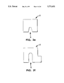
- FIG. 2a is an end view of a landscaping block in accordance with the invention.
- FIGS. 2b-2f are partial end views of alternate embodiments of a landscaping block in accordance with the invention.
- FIG. 2g is an end view of a landscaping block inserted into a substrate in accordance with the invention.
- FIGS. 3a-3c are end views of alternate embodiments of a landscaping block showing the groove in accordance with the invention.
- FIG. 3d is an end view of a landscaping block positioned over a pipe in accordance with the invention.
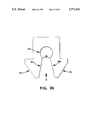
- FIG. 3e is an end view of a landscaping block positioned over electrical wiring in accordance with the invention.
- FIG. 4a is a perspective view of anchoring means in accordance with the invention.
- FIG. 4b is a perspective view of an alternate embodiment of anchoring means in accordance with the invention.
- FIG. 5a is a top view of a landscaping block in accordance with the invention.
- FIG. 5b is a top view of an alternate embodiment of a landscaping block in accordance with the invention.
- FIG. 5c is a top view of landscaping blocks aligned end to end to form a straight border in accordance with the invention.
- FIG. 5d is a top view of landscaping blocks aligned end to end to form a curved border in accordance with the invention.
- Figure 5e is a top view of landscaping blocks aligned end to end to form a curvilinear border in accordance with the invention.
- FIG. 6a is a perspective view of a landscaping block system in accordance with the invention.
- FIG. 6b is a perspective view of an alternate embodiment of a landscaping block system in accordance with the invention.
- FIG. 6c is a perspective view of an alternative embodiment of a landscaping block system in accordance with the invention.
- FIG. 7 generally shows the steps of manufacturing the landscaping blocks of the present invention.
- FIG. 8 is a front view of a block molding machine.
- FIG. 9 is a perspective view of an embodiment of the mold and platform of the present invention.
- FIG. 10a is a top view of an embodiment of the mold of the present invention.
- FIG. 10b is a top view of an alternate embodiment of the mold of the present invention.
- FIG. 11 is a sectional view of an embodiment of the mold along line x--x of the present invention.
- FIG. 12 is a perspective view of the compression head and shoe assembly of the present invention.
- FIG. 13 is a side view of the shoes of the present invention.
- FIG. 14 is a partial front view of the cut-off bar of the present invention.
- FIG. 15 is a front view of a splitter of the present invention.
- FIG. 16 is a top view of an alternate embodiment of the mold of the present invention.
- FIG. 17 is an end view of a landscaping block inserted into a substrate in accordance with one embodiment of the invention.
- Block 1 is made of a rugged, weather-resistant material, preferably pre-cast concrete. Other suitable materials are plastic, reinforced fibers, wood, metal, and stone.
- block 1 includes a top 2, a generally opposed bottom 3, and first and second generally opposed sides 4, 5, each side extending from top 2 to bottom 3.
- First and second generally opposed ends 6, 7 extend from top 2 to bottom 3 and from first side 6 to second side 7.
- Groove or channel 8 extends from bottom 3 into block 1 toward top 2, thereby having an opening at bottom 3, and extends from first end 6 to second end 7.
- block 1 extends approximately six inches from first end 6 to second end 7, four inches from top 2 to bottom 3, and four inches from first side 4 to second side 5 at lip 12. With these dimensions, block 1 is light enough for relatively easy transport and placement, provides adequate separation height and width for edging, as well as providing a deep enough mower strip to reduce hand-trimming, and allows for easy construction of a variety of straight and curved edging patterns. However, in order to meet the requirements of different applications, block 1 may have larger or smaller dimensions and varying proportions.
- sides 4,5 each have an upper face 9 and a lower face 10.
- Upper face 9 is generally above-ground when the block is in use, providing the visual edging or separation.
- Lower face 10 is at and below ground level and, in conjunction with groove 8, fixes block 1 in place in a substrate, typically dirt, sand, or other natural material.
- Upper face 9 extends from top 2 downward to inner edge 11 of lip 12. Face 9 may be planar and, in a preferred embodiment, includes beveled edge 13 adjacent top 2. As shown in FIGS. 2b-2d, top 2 and face 9 may have a variety of curved and/or textured shapes to meet the specific needs of any given application. Also, FIGS. 2e and 2f disclose alternate embodiments of block 1 with one or no lip 12.
- Lip 12 defines a transition from upper face 9 to lower face 10.
- Ledge 12 extends outwardly from upper face 9 to outer edge 14, at least about one-fourth inch and preferably about five-eighths inch.
- ledge 12 provides a mowing edge or strip that allows the wheels of a lawn mower to follow the contours of the block and allows the lawn mower to cut the grass adjacent the mowing strip, lessening the need for hand-trimming along the borders of a lawn.
- ledge 12 (1) provides, as shown in FIG. 17, an anchoring surface for placement of landscape rock 40, etc.; (2) serves as a screed board leveling surface for paver installations and provides interlock to prevent deterioration or loss of sub-base materials when used as a paver curb or edging; and (3) locks block 1 in place when used as an accent or passageway for conduit through a paved surface.
- lower face 10 Extending downward from outer edge 14 of ledge 12, lower face 10 has alignment strip 15 for easier placement of block 1 in the substrate and tapered portion 16 extends to bottom edge 17. The advantages of tapered portion 16 are discussed below.
- groove or channel 8 extends into block 1 from bottom 3 toward top 2.
- groove 8 is defined by generally opposed interior walls 18a, 18b.
- the width of slot 8, identified by arrow D, is the distance between the opposed interior walls 18a, 18b and is wide enough to receive commonly available black plastic edging 19.
- edging 19 may have various configurations. Typically, edging 19 have a lower bead or protrusion to allowing nailing or spiking in place.
- FIG. 4a shows commonly available flexible black PVC edging or strip 20 having opposed vertical walls 21a, 21b, and a top 22 and a bottom 23 edge. As shown in FIG.
- top edge 22 may include an elongated bead 24.
- edging 19 may be a planar strip made of aluminum or other suitable material. Edging 19 should be flexible to create the desired border shape and made of a suitable material for use in the desired substrate. Typically, edging 19 is partially embedded in a substrate by digging a small trench, and also may be fixed in place by stakes.
- Cavity 8 allows block 1 to fit over the top of and receive edging 19 or, as shown in FIG. 3b, block 1 can be locked onto edging 20 by the keyhole cross-sectional configuration of slot 8.
- opposed interior walls 18a, 18b define an upper annular receiving portion 25 for receiving the bead 24 of edging 20.
- Receiving portion 25 has a lower opening that forms neck 26 which prevents bead 24 from moving downward out of upper receiving portion 25 without substantial force exceeding the normal forces of the surrounding substrate during freeze/thaw cycles.
- the lower portions of walls 18a, 18b preferably taper outward or diverge towards sides 4, 5.
- groove 8 can be tapered from one end 6 to the other end 7, i.e., the slot width increases from one end 6 to the other end 7, for easier attachment and detachment of block 1 to strip 20.
- interior walls 18a, 18b are approximately parallel, defining a rectangular region for receiving a planar edging.
- interior walls define an upper curved shape at the top of groove 8 and a generally rectangular cross-sectional shape adjacent the bottom, accommodating a variety of edgings.
- Groove or channel 8 accomplishes several goals. First, blocks 1 can be locked into place over existing edging, which serves as an alignment guide, concealing the plastic or metal edging and providing an attractive, natural-looking edging. Second, slot 8 provides connection, coupling, aligning, and anchoring means, assisting in the installation of the edging. Finally, groove 8 allows for passage of pipe or other conduit for irrigation as shown in FIG. 3d or electrical wiring as shown in FIG. 3e along the edging.
- tapered portion 15 of lower face 10 on sides 4, 5 and diverging interior walls 18a, 18b provide several advantages.
- this embodiment is more easily installed by allowing block 1 to be more easily inserted into the substrate or soil than a flat bottomed surface.
- this embodiment is more easily inserted over edging 19 and locked into place.
- this embodiment is more resistant to frost heave than a flat bottomed surface, thereby retaining its position in the substrate over a period of years.
- this embodiment allows block 1 to fit over pipes or conduits that would otherwise be too wide.
- ends 6, 7 of block 1 provide another important aspect of the invention.
- end 6 is angled approximately 12 degrees from side 4 to side 5, while end 7 is approximately perpendicular to sides 4, 5.
- FIG. 5b shows another embodiment of block 1 having an angled end 6, but without lip 12.
- a preferred range of angles is 10-18 degrees.
- straight-end/angled-end block configurations allow for various straight (FIG. 5c), curved (FIG. 5d), curvilinear (FIG. 5e) borders without having to cut the blocks at the installation site. At least nine different shapes can be achieved using two blocks.
- the blocks may have both ends perpendicular to the sides, both ends angled from one side to the other, or ends with different angles. Preferred angles are those divisible into 360 degrees (i.e. 9, 12, 15, 18 and 24 degrees) so that the blocks can make a circle to be used around a tree, for example.
- top 2 and upper face 9 of sides 4, 5 There are numerous options for the appearance of top 2 and upper face 9 of sides 4, 5. Any of these surfaces can have a natural or "split" surface, smooth surface, corduroy or other striated surface.
- block 1 When block 1 is installed as shown in FIG. 2g, block 1 is inserted into a substrate 40, which may be earth or other material. Lip 12, preferably planar, and alignment strip 15 assist in placing block 1 in a preferred position wherein lip 12 is coplanar with the surrounding substrate. Lip 12 provides a mowing or spacer strip that separates top 2 and sides 4, 5 from the substrate by the length of lip 12. Lip 12 may be on one or both sides of block 1 depending on the application.
- a combination of blocks 1 can be used to create several landscaping block systems.
- the first system is discussed above and shown schematically in FIG. 6a.
- a new or existing edging 19 provides means for anchoring landscaping blocks 1 in a fixed position relative to the substrate 40.
- Anchoring means 19 is partially embedded in the substrate.
- bottom edge 23 is embedded in the substrate and bead 24 is above the upper surface of the substrate.
- the bottom groove or coupling means 8 at the bottom 3 of each block 1 is placed over and receives anchoring means 19 and the lower face 10 of each block 1 is also embedded in the substrate.
- the blocks 1 are aligned end to end along strip 19 thereby defining the landscaping border or edging.
- Another system is to insert the blocks 1 in a substrate end to end without using an edging 19, as shown in FIG. 6b. Again, lower face 10 is embedded in the substrate and upper face 9 and top 2 define the edging above the substrate surface. Grooves 8 then form an interior conduit that can receive pipes, conduit, electrical wiring, or function alone as a drainage conduit.
- FIG. 6c discloses a third landscaping block system.
- the blocks 1 are inserted into substrate 40 end to end, thereby fixing the blocks 1 in the substrate. Alignment of the blocks is maintained by use of connectors or coupling means 50 that connect the adjacent ends of the adjacent blocks.
- end 51 of block 60 is adjacent end 52 of block 61 and ends 51 and 52 are coupled by connector 50.
- the connectors can be tubing or a narrow strip that extends from the upper portions of adjacent grooves. Also, a single elongated tubing may pass through groove 8 from end to end the entire length of blocks.
- the method of the present invention is shown generally in FIG. 7.
- the block-forming materials typically water, cement, sand, and aggregate
- a block molding machine A wide variety of mixtures are known to make blocks having various characteristics such as strength, water absorbtion, density, shrinkage, and other factors meeting ASTM standards and depending on the desired application of the block.
- the mixture is prepared in any number of mixers known in the art.
- the mixture is then placed in a hopper which transports the mixture to a block molding machine shown generally in FIG. 8.
- Any block molding machine known in the art may be used.
- One machine found useful is the V3-12 Vibrapac, made by Besser Company, Avea, Mich.
- mold 70 sitting on or mated with generally planar steel pallet 71 as shown in FIG. 9. Specific aspects of the mold are discussed further below.
- the top of mold 70 is then scraped with a cut-off bar to remove excess mixture.
- Mold 70 is then subjected to vertical compression by head 72 moving downward on top of mold 70. Further details of head 72 are provided below. Head 72 acts to compress the fill within mold 70 for a period of time sufficient to form a solid, contiguous block. Generally, each block producing cycle has a duration of six to twelve seconds at a total load of 1500 to 2000 pounds. Additionally, mold 70 and horizontal platform 71 may be agitated during compression.
- platform 71 is lowered vertically away from mold 70 into a de-molding or stripped position and head 72 pushes the newly molded blocks downward through mold 70 so that they remain on platform 71. Head 72 is then raised vertically.
- blocks are cured by various means known in the art. Typically, blocks are cured in kilns for up to twenty-four hours under pressure and/or with steam. Once cured, the blocks may be split. Splitting methods such as hand-splitting with hammer and chisel, and machine splitting are known in the art. Additional details of the splitter used in connection with the present invention are provided below. After splitting, the blocks are palletized or otherwise packaged for shipment or storage.
- the method of the present invention is more specifically directed to molding landscaping block 1, having angled first end 6.
- mold 70 and compression head 72 are used.
- a top view of an embodiment of mold 70 is shown in FIG. 1Oa.
- Mold 70 has a front vertical wall 73, generally opposed back vertical wall 74, and generally opposed side walls 75a, 75b defining a generally rectangular, vertical outer wall or edge 76.
- Mold 70 further includes one or more volumes 77 extending from the top 78 to the bottom 79 of mold 70. Volume 77 is defined by a continuous vertical wall 80, described further below.
- block 1 is preferably molded vertically, i.e., the end 6 to end 7 dimension of block 1 is positioned vertically in mold 70 from top 78 to bottom 79.
- Vertical wall 80 which delimits volume 77, defines the cross-sectional shape of block 1.
- Vertical wall 80 includes a first pair of opposed sidewalls 81a, 81b and second pair of opposed sidewalls 82a, 82b.
- volume 83 in FIG. 10a defines a composite block 84 which comprises a first block 85 and second block 86 pair.
- Vertical wall 80 is configured so that blocks 85, 86 are positioned top to top, i.e., top 2 of block 85 is parallel and connected to top 2 of block 86 at plane 89.
- composite block 84 is split along plane 89 to form first block 85 and second block 86, each having a natural or split surface appearance at top 2.
- the first pair of opposed sidewalls 81a, 81b define bottom 3 of block 85 and bottom 3 of block 86, respectively.
- the second pair of opposed sidewalls 82a, 82b define sides 4, 5 of block 85 and sides 4, 5 of block 86.
- the second end 7 of blocks 85, 86, respectively, is defined by platform 71.
- the first angled end 6 of blocks 85, 86 are formed at the top 78 of mold 70.
- the top 78 of mold 70 has a saw-tooth or serrated shape.
- the angle of each side 100, 101 of top 99 defines the angle of the first end of each block 77 in the four respective rows 99 of mold 70.
- mold 70 is formed by a solid block of steel, for example, with volume 77 machined out of the solid block.
- compression means 72 includes a plurality of shoes 110, with each shoe 110 fitting over the top of each volume 77 to form angled end 6.
- the general head 72 and shoe 110 configuration is shown in FIG. 13.
- each shoe 110 has an angle complementary to the desired angle of first end 6 of each molded block 1. Therefore, when head 72 is compressed downward into mold 70 and each shoe 110 compresses into each volume 77, there is equal pressure across angled end 6, thereby forming a structurally sound angled end 6 on block 1.
- block machines may include a cut-off bar to scrape excess concrete off the top 78 of mold 70 and bottom of shoes 110.
- cut-off bar 111 has a serrated bottom edge 113 with angles complementary to the top 78 of mold 70.
- cut-off bar 111 is generally rectangular with planar top and bottom edges. In use, this embodiment would move up and down following the contours of the top 78 of mold 70 and shoes 110.
- cut-off bar 111 may have flexible top and bottom edges.
- volumes 77 in mold 70 are rotated ninety degrees, as shown in FIG. lOb.
- the angles on shoes 110 are also rotated ninety degrees to retain the same angled ends 6 on block 1.
- FIG. 16 generally shows a splitter 115 that can be used with the present invention.
- a top blade 116 and bottom blade 117 are used to split block 84 along the desired plane 89.
- top blade 116 is serrated with angles that are complementary to the angled end of composite block 84. Since the bottom of composite block 84 is flat, bottom blade 117 is straight. When composite block 84 is positioned in splitter 115 so that blades 116 and 117 are co-planar with plane 89, bottom blade 117 is forced upward and top blade 116 is forced downward, thereby applying generally equal pressure along plane 89 to split block 84 into blocks 85 and 86.
- sidewalls 82a, 82b may include v-shaped grooves 130a, 130b, respectively, that assists in providing a clean split along plane 89.
- a v-shaped groove 131 can be provided at the end of composite block 84 defining ends 6 of blocks 85 and 86 to assist in providing a straight split at plane 89.
- Mold 70 in FIG. 10a is configured so that when composite block 84 is split into separate blocks, the splitting process does not force adjacent blocks away from each other, thereby requiring additional handling or processing of the blocks. Referring to FIG. 10a, when the first line of composite blocks, identified as blocks A through D, are split, the angled end 6 on blocks A and D slopes downward toward walls 75a and 75b respectively. Therefore, blocks A and D do not fall away from blocks B and C.
- each pair of blocks 1 is formed with each pair having a block 1 with an angled end 6 complementary to the angled end 6 of the other block 1 of the pair, yielding twenty-four blocks per cycle. In a typical set-up, six to ten molding cycles may be completed per minute.
- FIG. 16 shows an alternate mold 120 where each volume 121 defines the cross-sectional shape of a single block 1. In this embodiment, splitter 115 is not required.
Abstract
Description
Claims (10)
Priority Applications (1)
| Application Number | Priority Date | Filing Date | Title |
|---|---|---|---|
| US08/741,344 US5771631A (en) | 1994-05-19 | 1996-10-29 | Landscaping block |
Applications Claiming Priority (2)
| Application Number | Priority Date | Filing Date | Title |
|---|---|---|---|
| US08/245,869 US5568994A (en) | 1994-05-19 | 1994-05-19 | Landscaping block |
| US08/741,344 US5771631A (en) | 1994-05-19 | 1996-10-29 | Landscaping block |
Related Parent Applications (1)
| Application Number | Title | Priority Date | Filing Date |
|---|---|---|---|
| US08/245,869 Continuation US5568994A (en) | 1994-05-19 | 1994-05-19 | Landscaping block |
Publications (1)
| Publication Number | Publication Date |
|---|---|
| US5771631A true US5771631A (en) | 1998-06-30 |
Family
ID=22928428
Family Applications (2)
| Application Number | Title | Priority Date | Filing Date |
|---|---|---|---|
| US08/245,869 Expired - Lifetime US5568994A (en) | 1994-05-19 | 1994-05-19 | Landscaping block |
| US08/741,344 Expired - Fee Related US5771631A (en) | 1994-05-19 | 1996-10-29 | Landscaping block |
Family Applications Before (1)
| Application Number | Title | Priority Date | Filing Date |
|---|---|---|---|
| US08/245,869 Expired - Lifetime US5568994A (en) | 1994-05-19 | 1994-05-19 | Landscaping block |
Country Status (1)
| Country | Link |
|---|---|
| US (2) | US5568994A (en) |
Cited By (22)
| Publication number | Priority date | Publication date | Assignee | Title |
|---|---|---|---|---|
| US6138405A (en) * | 1995-05-05 | 2000-10-31 | Matz; Warren W. | Lawn and guarding edging system (conduit extension) |
| US6449897B1 (en) | 1996-11-02 | 2002-09-17 | Johannes N. Gaston | Landscape edging system having adjustable blocks with recesses |
| US20030163955A1 (en) * | 1999-11-01 | 2003-09-04 | Harris Terry C. | Flexible rubber curb |
| US20030164574A1 (en) * | 2002-03-04 | 2003-09-04 | James Hammer | Apparatus and methods for making a masonry block with a roughened surface |
| US20040088929A1 (en) * | 2002-11-12 | 2004-05-13 | Keystone Retaining Wall Systems, Inc. | Landscaping block |
| US6754989B2 (en) * | 2002-05-06 | 2004-06-29 | Todd Eicher | Shielding apparatus secured to landscaping material for shielding a plant from weed growth |
| US20050034362A1 (en) * | 2003-08-13 | 2005-02-17 | Hector Tile Company, Inc. | Landscape edging, and methods |
| US20050108973A1 (en) * | 2001-10-18 | 2005-05-26 | Westblock Systems, Inc. | Wall block, system and mold for making the same |
| US20050183373A1 (en) * | 2004-01-29 | 2005-08-25 | Sami Mansour | Landscaping block and system for use |
| US20050252101A1 (en) * | 2004-05-12 | 2005-11-17 | Hector Tile Company, Inc. | Landscape edging blocks, systems, and methods |
| US20050284077A1 (en) * | 2004-06-11 | 2005-12-29 | Spratlen David S | Mortarless fence block system |
| US20060027226A1 (en) * | 2004-08-06 | 2006-02-09 | Custom Precast & Masonry, Inc. | Method and device for creating a decorative block feature |
| US20060159517A1 (en) * | 2005-01-18 | 2006-07-20 | Hagerman Joseph W | Core for paver and method |
| US20070157315A1 (en) * | 1999-08-30 | 2007-07-05 | Symantec Corporation | System and method for using timestamps to detect attacks |
| US20080053005A1 (en) * | 2006-09-01 | 2008-03-06 | Wilson Scott A | Landscape edge cover |
| US20090000233A1 (en) * | 2007-01-22 | 2009-01-01 | Westblock Systems, Inc. | Wall block and apparatus and method for making the same |
| US20090184440A1 (en) * | 2005-01-11 | 2009-07-23 | Dominic Chaussee | Molding equipment and method to manufacture stackable inter-engaging bricks, blocks, stones and the like with a smooth or embossed face |
| US20100132298A1 (en) * | 2007-10-03 | 2010-06-03 | Sci Materials | Retaining wall block and system |
| US20100186293A1 (en) * | 2009-01-28 | 2010-07-29 | Oldcastle Precast, Inc. | Landscape Edger With Adjustable Connection Mechanism |
| US9173350B1 (en) * | 2012-09-21 | 2015-11-03 | Jeffery M. Beutler | Lawn and garden edging |
| US9834902B2 (en) | 2015-02-25 | 2017-12-05 | Keystone Retaining Wall Systems Llc | Blocks, block systems and methods of making blocks |
| WO2022067129A1 (en) * | 2020-09-25 | 2022-03-31 | Collier Metal Specialties, Ltd. | Flush front landscape edging system |
Families Citing this family (35)
| Publication number | Priority date | Publication date | Assignee | Title |
|---|---|---|---|---|
| US5826372A (en) * | 1996-08-30 | 1998-10-27 | Parsons; Peter D. | Lawn edging |
| US6012254A (en) | 1996-11-02 | 2000-01-11 | Gaston; Johannes N. | Trenchless landscape edging system |
| US6226934B1 (en) | 1996-11-02 | 2001-05-08 | Johannes N. Gaston | Landscape edging system having block attachment member |
| US6324782B1 (en) | 1996-11-02 | 2001-12-04 | Johannes N. Gaston | Landscape edging system having block with recess |
| US5930947A (en) * | 1997-08-19 | 1999-08-03 | Eckhoff; Gerald J. | Landscape system apparatus |
| USD429005S (en) * | 1998-12-30 | 2000-08-01 | Rothbury International Inc. | Block |
| CA2282109C (en) | 1999-09-14 | 2005-12-20 | Robert Eugene Vasseur | Apparatus for creating a void under a structural concrete slab |
| GB9930288D0 (en) * | 1999-12-23 | 2000-02-09 | Toule Keith | Lawn edging device and method |
| AT411771B (en) * | 2001-07-09 | 2004-05-25 | Gernot Ing Goetzinger | CURB |
| GB2378883A (en) * | 2001-08-22 | 2003-02-26 | Michael Brendan Chamberlain | Concrete lawn edging stone |
| US7536825B2 (en) * | 2006-01-13 | 2009-05-26 | Joan Perotti | Interlocking landscape edging block |
| CA2571200A1 (en) * | 2006-12-14 | 2008-06-14 | Bruno Desrosiers | Precast curb system and method of installation thereof |
| US8128312B2 (en) * | 2007-01-17 | 2012-03-06 | Bart Stuchell | Support members and methods for the installation of brick patios, decks and paths |
| US7793598B2 (en) * | 2007-01-26 | 2010-09-14 | Strobl Jr Frederick P | Plastic panel, particularly for use as production pallet |
| US8475078B2 (en) * | 2008-11-22 | 2013-07-02 | Thomas Alan Denning | Containment device, method and system |
| EP2542723A2 (en) * | 2010-03-02 | 2013-01-09 | Keystone Retaining Wall Systems, Inc. | Retaining wall block system |
| WO2011109621A1 (en) | 2010-03-04 | 2011-09-09 | Keystone Retaining Wall Systems, Inc. | Retaining wall |
| USD663858S1 (en) | 2010-07-20 | 2012-07-17 | Keystone Retaining Wall Systems Llc | Landscaping block |
| USD647632S1 (en) | 2011-02-28 | 2011-10-25 | Keystone Retaining Wall Systems, Inc. | Landscaping block |
| USD647633S1 (en) | 2011-02-28 | 2011-10-25 | Keystone Retaining Wall Systems, Inc. | Landscaping block |
| USD647219S1 (en) | 2011-02-28 | 2011-10-18 | Keystone Retaining Wall Systems, Inc. | Landscaping block |
| USD656627S1 (en) | 2011-03-01 | 2012-03-27 | Keystone Retaining Wall Systems, Inc. | Landscaping block |
| USD656625S1 (en) | 2011-03-01 | 2012-03-27 | Keystone Retaining Wall Systems, Inc. | Landscaping block |
| USD656244S1 (en) | 2011-03-01 | 2012-03-20 | Keystone Retaining Wall Systems, Inc. | Landscaping block |
| USD666741S1 (en) | 2011-06-28 | 2012-09-04 | Keystone Retaining Wall Systems Llc | Landscaping block |
| USD666740S1 (en) | 2011-06-28 | 2012-09-04 | Keystone Retaining Wall Systems Llc | Landscaping block |
| USD667566S1 (en) | 2011-06-28 | 2012-09-18 | Keystone Retaining Wall Systems Llc | Landscaping block |
| USD667140S1 (en) | 2011-06-28 | 2012-09-11 | Keystone Retaining Wall Systems Llc | Landscaping block |
| USD667139S1 (en) | 2011-06-28 | 2012-09-11 | Keystone Retaining Wall Systems Llc | Landscaping block |
| US8490359B2 (en) | 2011-08-05 | 2013-07-23 | Joan M. Perotti | Landscape edging block system |
| USD688813S1 (en) | 2012-04-19 | 2013-08-27 | Keystone Retaining Wall Systems Llc | Landscaping block |
| US20130276401A1 (en) | 2012-04-19 | 2013-10-24 | Keystone Retaining Wall Systems Llc | Wall block and wall block system |
| US9181714B2 (en) | 2013-02-28 | 2015-11-10 | Keystone Retaining Wall Systems Llc | Multi-textured or patterned exposed surface of a landscaping block, wall block, patio block and block system |
| US9089096B1 (en) | 2013-10-09 | 2015-07-28 | Michael R. Ulrich | Pre-formed landscape barrier |
| US9267278B1 (en) * | 2014-08-21 | 2016-02-23 | James Gibson | Modular landscaping and waterproofing system |
Citations (23)
| Publication number | Priority date | Publication date | Assignee | Title |
|---|---|---|---|---|
| US315026A (en) * | 1885-04-07 | Eichaed heeley | ||
| US606151A (en) * | 1898-06-21 | Border for flower-beds | ||
| US683305A (en) * | 1900-07-21 | 1901-09-24 | Louis A Levin | Curb for sidewalks, lawns, &c. |
| US1677829A (en) * | 1928-07-17 | Pavement | ||
| US1746169A (en) * | 1926-03-08 | 1930-02-04 | William E Swanson | Resilient pavement |
| FR775634A (en) * | 1934-07-04 | 1935-01-05 | Shapes for paved gravel roads and slabs and curbs used in their construction | |
| US2196552A (en) * | 1938-10-28 | 1940-04-09 | William H F Garloff | Flashing block |
| US2471226A (en) * | 1945-04-13 | 1949-05-24 | Emil C Maccario | Concrete curb block |
| US2550945A (en) * | 1948-03-10 | 1951-05-01 | Living Stone Establishment | Building block |
| FR1333889A (en) * | 1962-06-19 | 1963-08-02 | Newly designed curbs | |
| US3354592A (en) * | 1965-06-08 | 1967-11-28 | William A Curci | Frangible masonry unit |
| US4074479A (en) * | 1977-04-25 | 1978-02-21 | Krupka Richard W | Lawn edging |
| DE2848991A1 (en) * | 1978-11-11 | 1980-05-14 | Karl Heinz Pastuch | Concrete lawn edging element - has vertical flange as side guide, and lower horizontal flange as support, for lawn mower cutting border |
| US4281473A (en) * | 1980-01-04 | 1981-08-04 | Emalfarb Mark A | Landscaping bed divider |
| US4314431A (en) * | 1979-12-31 | 1982-02-09 | S & M Block System Of U.S. Corporation | Mortar-less interlocking building block system |
| US4644685A (en) * | 1980-12-29 | 1987-02-24 | Suncast Corporation | Edging strip |
| US4761923A (en) * | 1986-08-07 | 1988-09-09 | Avon Plastics, Inc. | Landscape edging |
| US4802320A (en) * | 1986-09-15 | 1989-02-07 | Keystone Retaining Wall Systems, Inc. | Retaining wall block |
| US4971475A (en) * | 1989-07-13 | 1990-11-20 | Groupe Permacon Inc. | Precast curb system |
| US5092076A (en) * | 1991-01-04 | 1992-03-03 | Terreta Joseph P | Planter edging landscaping system |
| US5134817A (en) * | 1989-05-31 | 1992-08-04 | Anton Richardt | Border and landscaping bricks |
| US5139721A (en) * | 1989-07-13 | 1992-08-18 | Groupe Permacon Inc. | Method and apparatus for forming a precast curb system |
| US5261760A (en) * | 1992-03-10 | 1993-11-16 | Groupe Permacon Inc. | Precast curb section |
-
1994
- 1994-05-19 US US08/245,869 patent/US5568994A/en not_active Expired - Lifetime
-
1996
- 1996-10-29 US US08/741,344 patent/US5771631A/en not_active Expired - Fee Related
Patent Citations (23)
| Publication number | Priority date | Publication date | Assignee | Title |
|---|---|---|---|---|
| US315026A (en) * | 1885-04-07 | Eichaed heeley | ||
| US606151A (en) * | 1898-06-21 | Border for flower-beds | ||
| US1677829A (en) * | 1928-07-17 | Pavement | ||
| US683305A (en) * | 1900-07-21 | 1901-09-24 | Louis A Levin | Curb for sidewalks, lawns, &c. |
| US1746169A (en) * | 1926-03-08 | 1930-02-04 | William E Swanson | Resilient pavement |
| FR775634A (en) * | 1934-07-04 | 1935-01-05 | Shapes for paved gravel roads and slabs and curbs used in their construction | |
| US2196552A (en) * | 1938-10-28 | 1940-04-09 | William H F Garloff | Flashing block |
| US2471226A (en) * | 1945-04-13 | 1949-05-24 | Emil C Maccario | Concrete curb block |
| US2550945A (en) * | 1948-03-10 | 1951-05-01 | Living Stone Establishment | Building block |
| FR1333889A (en) * | 1962-06-19 | 1963-08-02 | Newly designed curbs | |
| US3354592A (en) * | 1965-06-08 | 1967-11-28 | William A Curci | Frangible masonry unit |
| US4074479A (en) * | 1977-04-25 | 1978-02-21 | Krupka Richard W | Lawn edging |
| DE2848991A1 (en) * | 1978-11-11 | 1980-05-14 | Karl Heinz Pastuch | Concrete lawn edging element - has vertical flange as side guide, and lower horizontal flange as support, for lawn mower cutting border |
| US4314431A (en) * | 1979-12-31 | 1982-02-09 | S & M Block System Of U.S. Corporation | Mortar-less interlocking building block system |
| US4281473A (en) * | 1980-01-04 | 1981-08-04 | Emalfarb Mark A | Landscaping bed divider |
| US4644685A (en) * | 1980-12-29 | 1987-02-24 | Suncast Corporation | Edging strip |
| US4761923A (en) * | 1986-08-07 | 1988-09-09 | Avon Plastics, Inc. | Landscape edging |
| US4802320A (en) * | 1986-09-15 | 1989-02-07 | Keystone Retaining Wall Systems, Inc. | Retaining wall block |
| US5134817A (en) * | 1989-05-31 | 1992-08-04 | Anton Richardt | Border and landscaping bricks |
| US4971475A (en) * | 1989-07-13 | 1990-11-20 | Groupe Permacon Inc. | Precast curb system |
| US5139721A (en) * | 1989-07-13 | 1992-08-18 | Groupe Permacon Inc. | Method and apparatus for forming a precast curb system |
| US5092076A (en) * | 1991-01-04 | 1992-03-03 | Terreta Joseph P | Planter edging landscaping system |
| US5261760A (en) * | 1992-03-10 | 1993-11-16 | Groupe Permacon Inc. | Precast curb section |
Non-Patent Citations (4)
| Title |
|---|
| Border Concepts, Inc. , Steel Landscape Edging Systems , Brochure 1992. * |
| Border Concepts, Inc., "Steel Landscape Edging Systems", Brochure 1992. |
| Pave Tech Inc. , Paver Edge Restraining System , Brochure 1992. * |
| Pave Tech Inc., "Paver Edge Restraining System", Brochure 1992. |
Cited By (34)
| Publication number | Priority date | Publication date | Assignee | Title |
|---|---|---|---|---|
| US6138405A (en) * | 1995-05-05 | 2000-10-31 | Matz; Warren W. | Lawn and guarding edging system (conduit extension) |
| US6449897B1 (en) | 1996-11-02 | 2002-09-17 | Johannes N. Gaston | Landscape edging system having adjustable blocks with recesses |
| US20070157315A1 (en) * | 1999-08-30 | 2007-07-05 | Symantec Corporation | System and method for using timestamps to detect attacks |
| US20030163955A1 (en) * | 1999-11-01 | 2003-09-04 | Harris Terry C. | Flexible rubber curb |
| US6964125B2 (en) * | 1999-11-01 | 2005-11-15 | Harris Terry C | Flexible rubber curb |
| US7591447B2 (en) | 2001-10-18 | 2009-09-22 | Westblock Systems, Inc. | Wall block, system and mold for making the same |
| US20050108973A1 (en) * | 2001-10-18 | 2005-05-26 | Westblock Systems, Inc. | Wall block, system and mold for making the same |
| US20030164574A1 (en) * | 2002-03-04 | 2003-09-04 | James Hammer | Apparatus and methods for making a masonry block with a roughened surface |
| US7100886B2 (en) | 2002-03-04 | 2006-09-05 | Westblock Systems, Inc. | Apparatus and methods for making a masonry block with a roughened surface |
| US20050116389A1 (en) * | 2002-03-04 | 2005-06-02 | Westblock Systems, Inc. | Apparatus and methods for making a masonry block with a roughened surface |
| US6754989B2 (en) * | 2002-05-06 | 2004-06-29 | Todd Eicher | Shielding apparatus secured to landscaping material for shielding a plant from weed growth |
| US20040088929A1 (en) * | 2002-11-12 | 2004-05-13 | Keystone Retaining Wall Systems, Inc. | Landscaping block |
| US20050034362A1 (en) * | 2003-08-13 | 2005-02-17 | Hector Tile Company, Inc. | Landscape edging, and methods |
| US20050183373A1 (en) * | 2004-01-29 | 2005-08-25 | Sami Mansour | Landscaping block and system for use |
| US20050252101A1 (en) * | 2004-05-12 | 2005-11-17 | Hector Tile Company, Inc. | Landscape edging blocks, systems, and methods |
| US20050284077A1 (en) * | 2004-06-11 | 2005-12-29 | Spratlen David S | Mortarless fence block system |
| US7168218B2 (en) | 2004-06-11 | 2007-01-30 | David Stalder Spratlen | Mortarless fence block system |
| US7124754B2 (en) | 2004-08-06 | 2006-10-24 | Custom Precast & Masonry, Inc. | Method and device for creating a decorative block feature |
| US20060027226A1 (en) * | 2004-08-06 | 2006-02-09 | Custom Precast & Masonry, Inc. | Method and device for creating a decorative block feature |
| US9764495B2 (en) * | 2005-01-11 | 2017-09-19 | Novabrik International Inc. | Molding equipment for molding inter-engaging bricks and method of using the same |
| US20090184440A1 (en) * | 2005-01-11 | 2009-07-23 | Dominic Chaussee | Molding equipment and method to manufacture stackable inter-engaging bricks, blocks, stones and the like with a smooth or embossed face |
| US20150090861A1 (en) * | 2005-01-11 | 2015-04-02 | Novabrik International Inc. | Molding equipment for molding inter-engaging bricks and method of using the same |
| US20060159517A1 (en) * | 2005-01-18 | 2006-07-20 | Hagerman Joseph W | Core for paver and method |
| US20080053005A1 (en) * | 2006-09-01 | 2008-03-06 | Wilson Scott A | Landscape edge cover |
| US20090000233A1 (en) * | 2007-01-22 | 2009-01-01 | Westblock Systems, Inc. | Wall block and apparatus and method for making the same |
| US20100132298A1 (en) * | 2007-10-03 | 2010-06-03 | Sci Materials | Retaining wall block and system |
| US20100186293A1 (en) * | 2009-01-28 | 2010-07-29 | Oldcastle Precast, Inc. | Landscape Edger With Adjustable Connection Mechanism |
| US9345199B2 (en) | 2009-01-28 | 2016-05-24 | Oldcastle Precast, Inc. | Landscape edger with adjustable connection mechanism |
| US9173350B1 (en) * | 2012-09-21 | 2015-11-03 | Jeffery M. Beutler | Lawn and garden edging |
| US9834902B2 (en) | 2015-02-25 | 2017-12-05 | Keystone Retaining Wall Systems Llc | Blocks, block systems and methods of making blocks |
| US10337163B2 (en) | 2015-02-25 | 2019-07-02 | Keystone Retaining Wall Systems Llc | Blocks, block systems and methods of making blocks |
| US10760242B2 (en) | 2015-02-25 | 2020-09-01 | Keystone Retaining Wall Systems Llc | Blocks, block systems and methods of making blocks |
| WO2022067129A1 (en) * | 2020-09-25 | 2022-03-31 | Collier Metal Specialties, Ltd. | Flush front landscape edging system |
| US11712007B2 (en) | 2020-09-25 | 2023-08-01 | Colmet Llc | Flush front landscape edging system |
Also Published As
| Publication number | Publication date |
|---|---|
| US5568994A (en) | 1996-10-29 |
Similar Documents
| Publication | Publication Date | Title |
|---|---|---|
| US5771631A (en) | Landscaping block | |
| US5588262A (en) | Landscaping block system | |
| US20180371705A1 (en) | Permeable surface covering units and permeable surface covering | |
| US6449897B1 (en) | Landscape edging system having adjustable blocks with recesses | |
| US6012254A (en) | Trenchless landscape edging system | |
| US7959380B2 (en) | Landscaping system | |
| US11413786B2 (en) | Articulating composite surface covering mat and method of making | |
| US6226934B1 (en) | Landscape edging system having block attachment member | |
| US8266844B2 (en) | Paved surface restraint and method of installation | |
| US5624615A (en) | Method of manufacturing modular stone panels | |
| US6324782B1 (en) | Landscape edging system having block with recess | |
| US20190008097A1 (en) | Landscape edging system | |
| US6185893B1 (en) | Paving block system | |
| US20050034362A1 (en) | Landscape edging, and methods | |
| US20050252101A1 (en) | Landscape edging blocks, systems, and methods | |
| US8956139B2 (en) | Mold system for forming multilevel blocks | |
| AU680146B2 (en) | Method of manufacturing a block | |
| WO2000004758A1 (en) | Improvements to edging | |
| US6588145B1 (en) | Method and apparatus for inhibiting grass from overgrowing pavement and fences | |
| CA2627851C (en) | Landscaping system | |
| KERBS | Q10 Kerbs/Edgings/Channels/Paving Accessories |
Legal Events
| Date | Code | Title | Description |
|---|---|---|---|
| AS | Assignment |
Owner name: MELLON BANK, N.A., PENNSYLVANIA Free format text: ASSIGNMENT OF ASSIGNORS INTEREST;ASSIGNOR:KEYSTONE RETAINING WALL SYSTEMS, INC.;REEL/FRAME:011996/0888 Effective date: 19991222 |
|
| FPAY | Fee payment |
Year of fee payment: 4 |
|
| AS | Assignment |
Owner name: WACHOVIA BANK, NATIONAL ASSOCIATION, AS ADMINISTRA Free format text: NOTICE OF GRANT OF SECURITY INTEREST;ASSIGNOR:KEYSTONE RETAINING WALL SYSTEMS, INC.;REEL/FRAME:014186/0634 Effective date: 20031031 |
|
| AS | Assignment |
Owner name: MELLON BANK, N.A., PENNSYLVANIA Free format text: CORRECTIVE;ASSIGNOR:KEYSTONE RETAINING WALL SYSTEMS, INC.;REEL/FRAME:015442/0347 Effective date: 19991222 |
|
| AS | Assignment |
Owner name: KEYSTONE RETAINING WALL SYSTEMS, INC., MINNESOTA Free format text: TERMINATION OF SECURITY INTEREST;ASSIGNOR:LASALLE BUSINESS CREDIT, LLC, AS AGENT FOR STANDARD FEDERAL BANK NATIONAL ASSOCIATION (AS SUCCESSOR TO MICHIGAN NATIONAL BANK, AS SUCCESSOR TO MELLON BANK, N.A.), AS AGENT;REEL/FRAME:015642/0260 Effective date: 20041124 |
|
| AS | Assignment |
Owner name: WACHOVIA BANK, NATIONAL ASSOCIATION, AS ADMINISTRA Free format text: NOTICE OF GRANT OF SECURITY INTEREST;ASSIGNOR:KEYSTONE RETAINING WALL SYSTEMS, INC.;REEL/FRAME:015676/0385 Effective date: 20041207 |
|
| FPAY | Fee payment |
Year of fee payment: 8 |
|
| AS | Assignment |
Owner name: KEYSTONE RETAINING WALL SYSTEMS, INC., MINNESOTA Free format text: TERMINATION OF SECURITY INTEREST IN PATENTS;ASSIGNOR:WACHOVIA BANK, NATIONAL ASSOCIATION, AS ADMINISTRATIVE AGENT;REEL/FRAME:017115/0305 Effective date: 20060131 |
|
| AS | Assignment |
Owner name: WACHOVIA BANK, NATIONAL ASSOCIATION, AS ADMINISTRA Free format text: SECURITY AGREEMENT;ASSIGNORS:KEYSTONE RETAINING WALL SYSTEMS, INC.;ARMORTEC, INC.;CONTECH ARCH TECHNOLOGIES, INC.;AND OTHERS;REEL/FRAME:017275/0045 Effective date: 20060131 |
|
| REMI | Maintenance fee reminder mailed | ||
| LAPS | Lapse for failure to pay maintenance fees | ||
| STCH | Information on status: patent discontinuation |
Free format text: PATENT EXPIRED DUE TO NONPAYMENT OF MAINTENANCE FEES UNDER 37 CFR 1.362 |
|
| FP | Lapsed due to failure to pay maintenance fee |
Effective date: 20100630 |
|
| AS | Assignment |
Owner name: WELLS FARGO BANK, N.A., NORTH CAROLINA Free format text: SECURITY AGREEMENT;ASSIGNORS:CONTECH CONSTRUCTION PRODUCTS, INC.;CONTECH BRIDGE SOLUTIONS INC.;CDS TECHNOLOGIES, INC.;AND OTHERS;REEL/FRAME:025026/0472 Effective date: 20100720 |