US5758580A - Printing unit using various ink types - Google Patents
Printing unit using various ink types Download PDFInfo
- Publication number
- US5758580A US5758580A US08/614,591 US61459196A US5758580A US 5758580 A US5758580 A US 5758580A US 61459196 A US61459196 A US 61459196A US 5758580 A US5758580 A US 5758580A
- Authority
- US
- United States
- Prior art keywords
- semi
- chemical agent
- printing unit
- atmosphere
- ink
- Prior art date
- Legal status (The legal status is an assumption and is not a legal conclusion. Google has not performed a legal analysis and makes no representation as to the accuracy of the status listed.)
- Expired - Fee Related
Links
Images


Classifications
-
- B—PERFORMING OPERATIONS; TRANSPORTING
- B41—PRINTING; LINING MACHINES; TYPEWRITERS; STAMPS
- B41F—PRINTING MACHINES OR PRESSES
- B41F13/00—Common details of rotary presses or machines
- B41F13/08—Cylinders
- B41F13/42—Guards or covers, e.g. for preventing ingress or egress of foreign matter
Definitions
- the present invention concerns a printing unit for a rotary printing press which can utilize various ink types.
- U.S. Pat. Nos. 5,309,838, and 5,375,518 each purport to disclose a system for keeping the printing plates of a printing press at a moderate temperature.
- a cooling air blower girder extends longitudinally over the printing plate surface and blows cold air onto the printing plate's surfaces in order to keep its temperature of a desired value.
- the blast air girder contains at least one heat exchanger and at least one blower as well as at least one air return duct, which together forms a cooling air cycle, through which the air blown onto the printing plate surface is returned to the air inlet of the heat exchanger and optionally mixed with fresh air blown by the blower once again through the heat exchanger onto the printing plate surface.
- the blast air girder purportedly presents an energy saving compact structural unit for keeping the printing plate surface at a moderate temperature.
- U.S. Pat. No. 5,452,657 purportedly relates to a temperature control system for printing press cylinders. It contains at least one compressed air line having at least one blast air opening for blowing cold air against a cylinder which is to be cooled. At least one recirculation circuit which is separate from the cold air of the compressed air line and by which air which has been blown by the blast air opening onto the cylinder is drawn off by means of a blower contained in the circulation circuit and is blown parallel to the cold air again onto the cylinder. In this way, the temperature of the cold air can be active, without prior change of temperature on the cylinder. The cold air deflected by the cylinder is returned to the cylinder for additional cooling.
- U.S. Pat. No. 5,098,478 relates to water based ink compositions.
- the water based ink composition comprises water, a pigment, a non-ionic surfactant having a solubility in water of less than about 0.5 wt % and a solubilizing agent sufficient to solubilize substantially all of the non-ionic surfactant.
- U.S. Pat. No. 5,026,755 purports to disclose a water based printing ink prepared from polyamid/acrylic graft copolymers. It is prepared by reacting the polyamid with the acrylic monomer or monomers in an alcohol solution in the presence of a free radical peroxidic initiator.
- the graft copolymer purports to be particularly useful as the resin component of a water based printing ink.
- German laid open patent application DE 41 19 348 A1 purports to disclose a method for offset printing and a printing unit for waterless offset printing.
- a conventional offset plate is used with a water based printing ink, containing a pigment, water, 5-50% water soluble macromolecular binding agents, a hygroscopic organic fluid, preferably a multivalent alcohol.
- the present invention reduces the formation of dried ink build-up by taking advantage of the fact that ink dry-up is caused by the evaporation of a volatile substance, e.g. VOC (volatile organic components), ammonia, ethanol amine or other amine compounds, and/or water, from the ink.
- a printing unit is provided which prevents or reduces the evaporation of the substance from the ink, thereby preventing premature ink dry up.
- the printing unit according to the present invention includes an inking mechanism, a plate cylinder, and a blanket cylinder supported within a frame. During operation of the printing unit, ink is applied as an ink film through the inking mechanism and onto a print form mounted on the print cylinder.
- a housing is mounted within the frame which at least partially surrounds the inking mechanism and print cylinder. In this manner, a semi-enclosed space surrounds the print cylinder and inking mechanism. Alternatively, the housing may also partially surround the blanket cylinder.
- the printing unit further includes a chemical supply for applying a chemical agent, e.g., water, VOC, ammonia, ethanol amine (or any other organic amine), in gaseous form into an atmosphere within the semi-enclosed space.
- a chemical agent e.g., water, VOC, ammonia, ethanol amine (or any other organic amine
- the printing unit further includes a cooling mechanism and a humidifier for controlling the atmospheric conditions within the semi-enclosed space.
- the cooling mechanism and humidifier improve printing conditions in a number of ways.
- the ability of the atmosphere within the semi-enclosed space to absorb the substance from the ink film is a function not only of the amount of the chemical agent in the atmosphere, but also of the temperature and humidity in the atmosphere.
- temperature and relative humidity affect print quality independent of ink-dry up problems. For example, if the temperature of the ink (or the surface the ink is being applied to) is too low, ink transfer will be impeded.
- a control unit controls the cooling mechanism, the humidifier, and the chemical supply to provide a suitable temperature, relative humidity, and chemical agent content in the atmosphere for high quality printing without ink dry up.
- the control unit monitors the temperature, humidity, and chemical agent content of the atmosphere within the semi-enclosed space via respective temperature, humidity, and chemical agent sensors, and then selectively activates the cooling mechanism, the humidifier, and the chemical supply as a function of the sensor readings.
- ink dry-up can be controlled by controlling the evaporation of ethanol amine (or, for example, another organic amine compound or ammonia) from the ink.
- the evaporation of ethanol amine from the ink in turn, can be prevented by injecting a sufficient amount of ethanol amine into the atmosphere within the semi enclosed space to prevent the evaporation of the ethanol amine from the ink.
- a concentration of 300-20,000 parts per million of ethanol amine (or ammonia) in the atmosphere will provide acceptable printing conditions for a water based ink containing 2% ethanol amine (or ammonia).
- the walls of the housing are hollow, and the cooling mechanism includes a cooling inlet and a cooling outlet, each connected to the hollow interior of the walls of the housing.
- a cooling agent e.g. cold water or air
- the cooling agent lowers the temperature of the housing, which, in turn, lowers the temperature within the semi-enclosed space.
- the outer surface of the housing is insulated so that the air within the semi-enclosed space surrounded by the inner surface of the housing remains cold.
- a cooling valve which is coupled either to the cooling inlet or the cooling outlet, is selectively actuated by the control unit as a function of one or more of the sensor outputs to control the cooling of the semi-enclosed space.
- the chemical supply includes a reservoir, a liquid solution containing the chemical agent (e.g., ethanol amine, another organic amine compound, or ammonia, in solution) and a heating element.
- the control unit can increase the chemical agent content of the atmosphere by activating the heating element, thereby causing more of the chemical agent in the solution to evaporate.
- the heating element is located relatively close to the reservoir.
- the chemical supply includes a gas intake connected to a supply mechanism for supplying the chemical agent in gaseous form.
- a valve is mounted between the gas intake and the supply mechanism, and controlled by the control unit.
- the present invention can be used with a variety of ink types, including, for example, water based inks, oleoresinous inks (containing hydrocarbons in the 270° F. boiling range, e.g. Magee oils), acrylate inks cured by radiation, and high viscosity inks known as paste inks.
- the present invention uses a water based paste ink which does not contain any volatile organic components (VOCs) so that the enclosed atmosphere is not subject to explosion.
- VOCs volatile organic components
- the chemical used as a pH increaser or drying prevention agent in the ink is prevented from evaporated by applying a chemical to the atmosphere in the semi-enclosed area within the housing.
- the chemical applied to the atmosphere is the same chemical which serves as the pH increaser or drying prevention agent in the ink.
- ethanol amine can be added to the atmosphere in the semi-enclosed area to prevent ink dry-up. If the amount of ethanol amine in the atmosphere causes the partial pressure of the ethanol amine in the atmosphere to be equal to the vapor pressure of the ethanol amine in the ink, then the ethanol amine will not evaporate from the ink into the atmosphere.
- the chemical agent can not only be used to prevent drying or precipitation of resin from the ink as described above, but also may serve as a pH increaser by increasing the amount of the substance in the ink.
- the substance in the ink is ethanol amine
- an increase in the amount of ethanol amine in the ink will increase the pH of the ink, thereby reducing drying or precipitation of resins and solvents in the ink.
- the amount of ethanol amine in the atmosphere causes the partial pressure of the ethanol amine in the atmosphere to be greater than the vapor pressure of the ethanol amine in the ink, then the ethanol amine will flow from the atmosphere into the ink, thereby increasing the amount of the ethanol amine in the ink, and the pH of the ink.
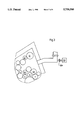
- FIG. 1 shows a printing unit according to the present invention.
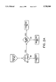
- FIG. 2a-e show flow charts for a control unit of the printing press of FIG. 1.
- FIG. 3 shows an alternate embodiment of a chemical agent supply according to the present invention.
- FIG. 4 shows an alternate embodiment of a cooling mechanism according to the present invention.
- FIG. 5 shows a further embodiment of the present invention.
- FIG. 1 shows a printing unit 1 according to the present invention for preventing premature dry-up of ink.
- the printing unit 1 of a rotary printing press includes an upper inking unit 45, an upper print cylinder 3 and an upper blanket cylinder 2, which cooperate to print ink onto an upper side of a web of material 4.
- a cylinder 13 is shown below the web 4.
- a print form suitable for printing with inks (for example, water based inks) is mounted on the print cylinder 3. If the printing unit 1 is configured as a non-perfecting press, the cylinder 13 is an impression cylinder. If the printing unit 1 is configured as a perfecting press, the cylinder 13 is a blanket cylinder and the printing unit 1 includes a corresponding lower inking unit and lower print cylinder (not shown).
- the inking unit 45 includes an ink fountain roller 12 supplying the ink (e.g., water based ink) to rollers 5-11, 46-47 of the inking unit 45.
- the ink e.g., water based ink
- a first form roller 5, a second form roller 6 and a third form roller 7 apply the thin film of ink onto the surface of the print form(s) which are mounted on the surface of the print cylinder 3.
- the film of ink takes through the respective roller surfaces of the inking unit of the printing unit 1, there is arranged a metering roller 47, a plurality of distribution rollers 8, 9, 11, and a plurality of vibrator rollers 46.
- the number, type, and arrangement of rollers in the inking unit 45 can be different from the arrangement of FIG. 1.
- the print form may be configured as a flat printing plate mounted on the surface of the print cylinder 3 by its leading and trailing edges, or as a sleeve shaped print form mounted axially over the print cylinder. Over the circumference of the blanket cylinder 2 there can either be arranged a conventional flat rubber blanket or a sleeve-shaped printing blanket.
- the blankets and print forms can be installed and removed in any conventional manner.
- the inking unit 45 of the printing unit 1 and the printing unit cylinders 2, 3 are encapsulated within a housing 14.
- the inking unit 45 (including rollers 5-12, 46-47), the cylinders 2, 3, and the housing 14 are supported by sidewalls (not shown).
- the housing 14 forms a semi-enclosed area 100 around the ink unit 45 and the cylinders 2, 3.
- the housing forms a semi-enclosed area around the inking unit 45, and print and blanket cylinders as shown.
- the housing 14 could also be constructed around the lower inking unit, plate and blanket cylinders.
- the housing 14 is hollow and has an outer wall 14a and an inner wall 14b.
- An insulating material 15 surrounds the outer wall 14a.
- An air intake 16 extends from the outside the housing 14 through the inner wall 14b.
- air passes through an air filter 19 mounted within the air intake 16 and into the semi-enclosed area 100.
- a humidifier 18 is mounted below the air filter 19 for controlling the humidity within the semi-enclosed area.
- the humidifier 18 is coupled to, and controlled by, a control unit 37.
- An air exhaust 53 also extends from outside the housing 14 through the inner wall 14b.
- the air exhaust 53 includes an air blower 29 for exhausting air from the semi-enclosed area 100.
- the air blower 29 is also connected to, and controlled by, the control unit 37.
- the air intake 16 further includes a reservoir 20 which is connected to a supply hose 22 and grounded.
- the supply hose 22 includes a supply valve 33.
- the reservoir 20 could be located within the semi-enclosed area 100, or connected to the semi-enclosed area via a separate intake.
- the reservoir 20 contains an amount of a chemical agent, e.g,. ethanol amine, another organic amine compound, or ammonia, in a dilute solution.
- a sensor 21 is mounted within the reservoir for monitoring the level of the reservoir 20. Preferably, the level of the reservoir is periodically checked by the sensor 21 to provide a precise reading of the solution level.
- a cooling inlet 23 and cooling outlet 24 each extend from outside the housing 14 through the outer wall 14a.
- a cooling agent e.g. cold water or cold air
- the flow of the cooling agent through the inlet 23 and outlet 24 can be adjusted by controlling valve 35 which can be mounted at the outlet 24, at the inlet 35, or at both the outlet and inlet.
- the valve 35 is mounted at the outlet 24 as shown.
- the valve 35 is connected to, and controlled by, the control unit 37 for controlling the flow of the cooling agent through the hollow interior of the housing 14.
- a first sensor set 30, including first sensors 30.1, 30.2, and 30.3, and a second sensor set 31, including second sensors 31.1, 31.2, 31.3, are arranged within the semi-enclosed area 100 of the housing 14.
- the first sensor set 30 is arranged adjacent to the inking unit 45 to monitor the atmosphere surrounding the inking unit 45.
- the second sensor set 31 is arranged adjacent to the cylinders 2, 3 to monitor the atmosphere surrounding the cylinders 2, 3.
- the first and second sensor sets 30, 31 are connected to the control unit 37.
- Each sensor set 30, 31 includes a respective temperature sensor 30.1, 31.1, a relative humidity sensor 30.2, 31.2, and a chemical agent (e.g., ethanol amine, other organic amine, or ammonia) sensor 30.3 and 31.3. It is understood that additional sensor sets can be mounted in key locations as necessary.
- Each of the sensors 30.1, 30.2, 30.3, 31.1, 31.2, 31.3 have respective output(s) which are individually connected to the control unit 37.
- a central control system 50 includes the control unit 37.
- the control unit 37 includes an input 38 for receiving input from the sensors 30, 31 and an output 39 for controlling the air blower 29, the humidifier 18, the supply valve 33, and the cooling outlet valve 35.
- a display 40 and keyboard 41 are connected to the control unit 37 to allow a press operator to monitor the status of the sensors and to control the state of the valves and the air blower.
- the control unit maintains the temperature, relative humidity, and chemical agent content of the atmosphere within the semi-enclosed area within desired ranges.
- the precise temperature and humidity levels, and the type and amount of chemical agent may vary depending on the type of ink and the location within the housing.
- the present invention can be used with a variety of ink types, including, for example, water based inks, oleoresinous inks (containing hydrocarbons in the 240°-320° F. boiling range, e.g., Magee oils), acrylate inks cured by radiation, and high viscosity inks known as paste inks.
- the present invention uses a water based ink, which does not contain any volatile organic components (VOCs).
- VOCs volatile organic components
- the temperature should be kept within a temperature range which is high enough to promote good ink transfer, and low enough to prevent toning.
- the relative humidity should be low enough to prevent condensation, but high enough to minimize evaporation of water from the ink.
- the amount of chemical agent in the atmosphere should be sufficient to reduce the evaporation of the chemical substance acting as a pH increaser or drying prevention agent in the ink.
- the amount of chemical agent needed is a function of the nature of the chemical agent, the nature of the chemical substance in the ink, the relative humidity, and the temperature of the atmosphere within the semi-enclosed area 100 adjacent to the ink transferring surfaces.
- the desired levels for the temperature, humidity, and chemical agent can be empirically determined through testing various temperature, humidity, and chemical agent levels with the desired ink.
- a press operator inputs a desired temperature level, relative humidity level, and chemical agent level for the printing unit 1 to the control unit 37 via the keyboard 41.
- the control unit 37 monitors the outputs of the temperature sensors 30.1, 31.1, the relative humidity sensors 30.2, 31.2, and the chemical agent sensors 30.3, 31.3. If the control unit determines that the temperature is above the desired level, it will open the cooling outlet valve 35 and circulate the cooling agent through the hollow interior of the housing 14, thereby cooling the atmosphere within the semi-enclosed area 100, e.g., by conduction, convection, and radiation. Once the temperature drops below the desired temperature level, the valve 35 will be closed.
- the control unit determines that the humidity is below the desired level, it will activate the humidifier thereby adding moisture to the air traveling through the air intake 16 into the semi-enclosed area 100, and increasing the humidity of the atmosphere within the semi-enclosed area 100. Once the humidity rises above the desired humidity level, the humidifier will be turned off. As a result, the humidity in the semi-enclosed area 100 will continually oscillate about the desired humidity level.
- control unit determines that the chemical agent level is below the desired level, it will activate a heater 48 thereby causing the chemical agent in the reservoir to evaporate from the solution more quickly into the air passing through the air intake 16 to the semi-enclosed area and increasing the chemical agent content of the atmosphere within the semi-enclosed area 100.
- the heater 48 is turned off. As a result the chemical agent content in the semi-enclosed area will continually oscillate about the desired level.
- the print form is suitable for receiving and transferring an image using water based inks.
- "waterless” type printing plates such as those manufactured by Toray Industries, or those described in U.S. Pat. No. 5,370,906 to Danker are also suitable for printing with water based inks.
- a Toray Industries printing plate having an aluminum oxide substrate with an image area coated with a photopolymer whose surface is hydrophilic in nature and a non-image area coated with a silicone polymer may be used.
- An illustrative water-based ink for use with the present invention may include the components set forth below.
- the water phase of the ink is supplied by the water present in the acrylic resin latex, hydroxypropyl cellulose, hydroxyethyl ethylene urea, and the maleated rosin ester.
- the pH increaser in the ink is supplied by the ethanol amine:
- the relative humidity, temperature, and ethanol amine level within the semi-enclosed area 100 in the housing 14 are maintained at certain predetermined levels.
- a water based ink containing 2% ethanol amine it has been found that by providing an atmosphere containing 300 to 20,000 parts per million of ethanol amine at a temperature of 93°-95° F. and a relative humidity between 75% and 95%, high print quality can be maintained.
- these levels are merely illustrative, and may vary in accordance with a number of factors including the particular construction of the printing unit, the particular composition of the water based ink, print form and paper being used.
- the temperature, relative humidity, and ethanol amine levels are monitored by the control unit, and the atmosphere within the semi-enclosed area 100 is maintained within the desired temperature, relative humidity, and ethanol amine level ranges by selectively activating the cooling outlet valve 35, the heater 48, and the humidifier 18 as described above.
- the control unit 37 When a printing press is first started, the printing unit components 2, 3, 5-12, 14-15, 46-47 will be relatively cold. Therefore, the control unit 37, by monitoring the temperature sensors 30.1, 31.1, will determine that the temperature within the semi-enclosed area 100 is below the desired temperature level for the water based ink, print form, and paper being used. The control unit 37 will then display a message on the display 40 advising the press operator to pre-heat the printing unit 1 prior to printing. Such a preheating could be accomplished by running the press while off impression until the temperature within the semi-enclosed area 100 has reached the desired level. Alternatively, a heating element (not shown) could be arranged within the semi-enclosed area to pre-heat the atmosphere, and controlled via the control unit 37.
- the temperature within the printing unit 1 may rise above the desired temperature level.
- the control unit 37 by monitoring the temperature sensors 30.1, 31.1, will determine that the temperature within the housing 14 is above the desired temperature level for the water based ink, print form, and paper being used, and will then lower the temperature within the semi-enclosed are by opening the cooling outlet valve 35 as described above.
- the rise in temperature caused by operation of the press may also affect the relative humidity within semi-enclosed area 100 of the housing 14. For example, an increase in temperature results in a decrease in relative humidity, thereby causing the atmosphere surrounding the surface of the rollers carrying the ink film to become too dry. This, in turn, causes evaporation of ethanol amine and water from the ink.
- the control unit 37 by monitoring the humidity sensors 30.2, 31.2, or additional sensors placed in critical areas, will determine that the humidity within the housing 14 is below the desired level for the water based ink being used. Upon determining that the humidity is below the desired level, the control unit will increase the humidity by controlling the humidifier 18 as described above.
- the percentage of ethanol amine in the air within the semi-enclosed area 100 of the housing 14 will also affect ink dry-up.
- the control unit 37 by monitoring the sensors 30.3, 31.3, will determine that the ethanol amine level within the housing 14 is below the desired level for the water based ink being used.
- the control unit 37 can then increase the ethanol amine level in the atmosphere by activating the heater 48. If the ethanol amine level rises above acceptable levels, the amount of ethanol amine in the semi-enclosed area within the housing 14 can be decreased by activating the air blower 29 to remove the excess ethanol amine from the semi-enclosed area.
- FIGS. 2a-e show illustrative flow charts for the control unit 37 of FIG. 1.
- the control unit 37 monitors the output of the sensors and compares them to various set point values and alarm values as set forth below. Based upon these comparisons, the control unit 37 controls the valves 33, 35, the humidifier 18, the air blower 29, and the heater 48.
- the above referenced flow charts are merely illustrative, and could be replaced with any suitable algorithm known in the art for matching a measured value to a desired value.
- the flow charts of FIGS. 2a-e may result in measured values which oscillate about the desired value, it is contemplated that other known closed loop control algorithms can be used which would reduce or eliminate these oscillations.
- sensors and control devices can be added to control the temperature, humidity, and chemical agent concentration more locally to provide for control over local variation in the humidity, temperature, chemical substance levels.
- additional sensors and control devices can be added to control the temperature, humidity, and chemical agent concentration more locally to provide for control over local variation in the humidity, temperature, chemical substance levels.
- the control unit 37 maintains a set point R and alarm R level which establish a minimum and maximum relative humidity value for the atmosphere within the semi-enclosed area 100; a set point T and alarm T level which establish a minimum and maximum temperature value for the atmosphere within the semi-enclosed area 100; and a set point A and alarm A level which establish a minimum and maximum ethanol amine level for the atmosphere within the semi-enclosed area 100.
- These alarm and set point levels are selected as a function of the particular ink being used. For example, for a water based ink containing 2% ethanol amine, the following set points and alarms have been found to be effective for controlling the atmosphere within the semi-enclosed area:
- additional alarm values may also be useful. For example, extremely low relative humidity, e.g., below 35%, may increase the likelihood of a web break due to the high tack of the ink at low humidity. Therefore, an additional relative humidity alarm could be triggered by the relative humidity dropping below 35%.
- the humidifier 18 will be turned on until the set point R is reached.
- the cooling outlet valve 35 will be opened if there is no alarm R , T, or A and the average of the temperature signals (T 1 +T 2 )/2 are above the set point T . If the average of the ethanol amine percentage signals (A 1 +A 2 )/2 is below the set point A and there is no alarm R , T, or A, the heater is turned on until the set point A is reached.
- the ethanol amine solution level (L) in the reservoir 20 can be checked via a level sensor 21. If the Level (L) is below a set point L , and there is no alarm R , T, or A, the supply valve 33 is turned on until the set point L is reached.
- a pH sensor 49 may be mounted within an ink pan 49 of the printing unit and connected to the control unit 37. It has been found that the tendency for an ink to dry prematurely is related to the pH level of the ink. Specifically, the lower the pH level of the ink, the lower the ethanol amine content of the ink, and the faster the ink will dry.
- the desired pH level can be set as a set poin pH . If the pH reading is below the set point pH , and there is no alarm R , T, or A, then the heater 48 will be turned on. The heat from the heater 48 will cause additional ethanol amine to evaporate from the reservoir 20 into the semi-enclosed space 100.
- the pH sensor 49 may be used as a substitute for the ethanol amine sensor 30.3, or in addition to the ethanol amine sensor 30.3.
- the humidifier and humidity sensor can be eliminated, and the humidity in the semi-enclosed space 100 can be controlled by adding an appropriate amount of water to the ethanol amine solution in the reservoir 20. Since the water in the ethanol amine solution will, like the ethanol amine, evaporate as a function of the temperature and relative humidity of the atmosphere in the semi-enclosed space, by selecting the proper ratio of water to ethanol amine in the ethanol amine solution, the humidity in the semi-enclosed space will be maintained within the desired range. While this approach provides the advantage of eliminating the humidifier and humidity sensor, it requires that more attention be paid to the composition of the ethanol amine solution.
- the reservoir 20 and heater 48 can be replaced with an ethanol amine gas inlet pipe 52 connected to a source of gaseous ethanol amine 53 through a valve 52a.
- the ethanol amine content of the atmosphere can be increased by controlling the supply of ethanol amine gas into the semi-enclosed area 100.
- FIG. 4 shows another embodiment of the present invention. Similar components bear the identical reference numbers as FIG. 1.
- a closed loop is formed between the air intake 16 and the air blower 29 and a cooling unit 60 is arranged in the closed loop between the air intake 16 and the air exhaust 53.
- the air blower 29 continuously circulates air out of the semi-enclosed area 100, through the cooling unit 60, the air filter 19, the humidifier 18, over the reservoir 20, and back into the semi-enclosed area 100.
- the humidifier 18 and heater 48 are activated as a function of the sensor outputs in the same manner as described above with regard to FIGS. 1-3.
- the cooling unit 60 replaces the cooling inlet 23 and cooling outlet 24 of FIG.
- FIG. 5 shows an alternative embodiment of the present invention, with similar components bearing similar reference numerals to FIG. 1.
- a first sub-housing 14.1 having insulation 15.1 surrounds a fountain roller 12, a metering roller 47, and a distribution roller 8.
- a second sub-housing 14.2 having insulation 15.2 surrounds form rollers 5, 6, 7, vibrator rollers 46, and a back side of the print cylinder 3 and blanket cylinder 2.
- a third sub-housing 14.3 having insulation 15.3 surrounds a front side of the print cylinder 3 and blanket cylinder 2.
- Each sub-housing includes respective temperature (30.1, 30'.1, 30".1), humidity (30.2, 30'.2, 30".2), and chemical agent (30.3, 30'.3, 30".3) sensors for monitoring the atmosphere within the respective semi-enclosed areas 100. 1, 100.2, 100.2.
- each housing includes respective cooling inlets 23.1, 23.2, 23.3 and cooling outlets 24.1, 24.2, 24.3 for circulating cooling agent through the housing 14.1, 14.2, 14.3.
- each sub-housing includes a respective air intake 16.1, 16.2, 16.3 including air filters 19.1, 19.2, 19.3, humidifiers 18.1, 18.2, 18.3, reservoirs 20.1, 20.2, 20.3, and heaters 48.1, 48.2, 48.3 for controlling the humidity and chemical agent levels in the atmosphere in the semi-enclosed areas 100.1, 100.2, 100.3.
- each sub-housing includes blowing devices 29.1, 29.2, 29.3 and air exhausts 53.1, 53.2, 53.3 for exhausting the atmosphere from the semi-enclosed areas 100.1, 100.2, 100.3.
- the control unit 37 includes respective inputs connected to the sensors (30.1, 30.2, 30.3, 30'.1, 30'.2, 30'.3, 30".1.
- each semi-enclosed area (100.1, 100.2, 100.3) can be independently controlled. It should be noted that the subdivisions shown in FIG. 5 are merely illustrative. For example, in certain applications, it may be advantageous to provide separate sub-housings for the print cylinder and blanket cylinder, or to enclose the entire inking unit in a single sub-housing. It may be desirable to subdivide the enclosed space across the printing rolls so that side to side or middle variations inherent in the printing unit may be adequately compensated.
- evaporation of ethanol amine and water may be of less concern in sub-housing 14.1 than in sub-housings 14.2 and 14.3. Therefore, a press operator might wish to set the humidity and ethanol amine set points for sub-housing 14.1 lower than in sub-housings 14.2 and 14.3. In this manner, a different set point and alarm can be set for the front side of the print and blanket cylinders than for the fountain roller 12, metering roller 47 and distribution roller 8.
- cooling units can be provided for circulating a cooling agent through one or more of the print cylinders, blanket cylinders, vibrator rollers, and fountain rollers of the printing unit as described in more detail in U.S. patent application Ser. No. 08/615,351 entitled Printing Unit for Water Based Inks, filed on even date herewith (attorney docket 1649/70, named inventor Roland T. Palmatier), the specification of which is hereby incorporated by reference.
- By controlling the circulation of cooling agent through one or more of the cylinders and rollers additional control over the temperature of the ink carrying surfaces of the cylinders and rollers can be obtained.
Abstract
Description
______________________________________ Component Amount, wt. % ______________________________________ Styrene/maleic anhydride resin 12Phthalocyanine Blue pigment 12 Acrylic resin latex (50% wt. % solids) 5 Hydroxypropylcellulose (3% wt. % solids) 10 Hydroxyethylethylene urea (70% wt % solids) 8Monoethanol amine 2Polyethylene Wax 2 Ethoxylatedacetylenic diol surfactant 2 Maleated rosin ester (50 wt. % solids) 47 Total 100 ______________________________________
Claims (41)
Priority Applications (9)
| Application Number | Priority Date | Filing Date | Title |
|---|---|---|---|
| US08/614,591 US5758580A (en) | 1996-03-13 | 1996-03-13 | Printing unit using various ink types |
| JP09532230A JP2001502253A (en) | 1996-03-13 | 1997-02-26 | Printing unit that uses various types of ink |
| EP97905087A EP0886578B1 (en) | 1996-03-13 | 1997-02-26 | Printing unit using various ink types |
| DE69704850T DE69704850T2 (en) | 1996-03-13 | 1997-02-26 | PRINTING UNIT USING DIFFERENT COLORS |
| AT97905087T ATE201166T1 (en) | 1996-03-13 | 1997-02-26 | PRINTING UNIT USING DIFFERENT COLOR TYPES |
| CA002247250A CA2247250A1 (en) | 1996-03-13 | 1997-02-26 | Printing unit using various ink types |
| PCT/EP1997/000908 WO1997033751A1 (en) | 1996-03-13 | 1997-02-26 | Printing unit using various ink types |
| AU18769/97A AU1876997A (en) | 1996-03-13 | 1997-02-26 | Printing unit using various ink types |
| US09/004,967 US6209456B1 (en) | 1996-03-13 | 1998-01-09 | Web- and sheet-fed printing unit using various ink types, particularly water-based inks |
Applications Claiming Priority (1)
| Application Number | Priority Date | Filing Date | Title |
|---|---|---|---|
| US08/614,591 US5758580A (en) | 1996-03-13 | 1996-03-13 | Printing unit using various ink types |
Related Parent Applications (1)
| Application Number | Title | Priority Date | Filing Date |
|---|---|---|---|
| US08/615,351 Continuation-In-Part US5694848A (en) | 1996-03-13 | 1996-03-13 | Printing unit for water based inks |
Related Child Applications (1)
| Application Number | Title | Priority Date | Filing Date |
|---|---|---|---|
| US09/004,967 Continuation-In-Part US6209456B1 (en) | 1996-03-13 | 1998-01-09 | Web- and sheet-fed printing unit using various ink types, particularly water-based inks |
Publications (1)
| Publication Number | Publication Date |
|---|---|
| US5758580A true US5758580A (en) | 1998-06-02 |
Family
ID=24461935
Family Applications (1)
| Application Number | Title | Priority Date | Filing Date |
|---|---|---|---|
| US08/614,591 Expired - Fee Related US5758580A (en) | 1996-03-13 | 1996-03-13 | Printing unit using various ink types |
Country Status (8)
| Country | Link |
|---|---|
| US (1) | US5758580A (en) |
| EP (1) | EP0886578B1 (en) |
| JP (1) | JP2001502253A (en) |
| AT (1) | ATE201166T1 (en) |
| AU (1) | AU1876997A (en) |
| CA (1) | CA2247250A1 (en) |
| DE (1) | DE69704850T2 (en) |
| WO (1) | WO1997033751A1 (en) |
Cited By (11)
| Publication number | Priority date | Publication date | Assignee | Title |
|---|---|---|---|---|
| US6152032A (en) * | 1998-11-05 | 2000-11-28 | Heidelberger Druckmaschinen Ag | Mist containment system for a spray dampener system |
| US6209456B1 (en) * | 1996-03-13 | 2001-04-03 | Heidelberger Druckmaschinen Ag | Web- and sheet-fed printing unit using various ink types, particularly water-based inks |
| US6802256B1 (en) * | 1998-01-20 | 2004-10-12 | Heidelberger Druckmaschinen Ag | Method and device for preventing uncontrolled spread of powder in a printing machine |
| US6823795B2 (en) * | 2001-05-16 | 2004-11-30 | Mars, Inc. | Method and apparatus for forming multicolor registered images on edible pieces |
| US20050005803A1 (en) * | 2001-11-22 | 2005-01-13 | Georg Schneider | Utilization of a printing ink in a printing group and printing group of a rotary printing press |
| US20070089623A1 (en) * | 2005-10-18 | 2007-04-26 | Mitsubishi Heavy Industries, Ltd. | Water-Based-Varnish Drying Apparatus and Printing Press |
| US20080053321A1 (en) * | 2006-08-29 | 2008-03-06 | Malcolm Gordon Armstrong | Manufacture of biosensors by continuous web incorporating enzyme humidification |
| US20080202368A1 (en) * | 2007-02-27 | 2008-08-28 | Mitsubishi Heavy Industries, Ltd. | Printing method and printing press |
| US20090189964A1 (en) * | 2008-01-28 | 2009-07-30 | Hitachi Industrial Equipment Systems Co., Ltd. | Ink jet recording device |
| US20100097417A1 (en) * | 2007-03-27 | 2010-04-22 | Anthony Hill | Ink Jet Printing |
| US20170291408A1 (en) * | 2014-10-20 | 2017-10-12 | Mitsubishi Heavy Industries Printing & Packaging Machinery, Ltd. | Flexographic printer and box-making machine |
Families Citing this family (4)
| Publication number | Priority date | Publication date | Assignee | Title |
|---|---|---|---|---|
| JP4735916B2 (en) * | 2001-04-02 | 2011-07-27 | 大日本印刷株式会社 | Gravure printing machine |
| DE10157271B4 (en) * | 2001-11-22 | 2005-02-03 | Koenig & Bauer Ag | Method and device for controlling a temperature of a forme cylinder |
| JP5509646B2 (en) * | 2008-09-03 | 2014-06-04 | 凸版印刷株式会社 | Topographic printing device |
| JP6741258B2 (en) * | 2016-04-13 | 2020-08-19 | 国立研究開発法人産業技術総合研究所 | Transfer printing apparatus and transfer printing method |
Citations (28)
| Publication number | Priority date | Publication date | Assignee | Title |
|---|---|---|---|---|
| GB549235A (en) * | 1939-11-22 | 1942-11-12 | Michigan Res Lab Inc | Improvements in or relating to printing |
| US2319853A (en) * | 1939-05-10 | 1943-05-25 | Goss Printing Press Co Ltd | Printing method and means |
| US2556262A (en) * | 1946-11-16 | 1951-06-12 | Time Inc | Method of coating paper |
| CA474605A (en) * | 1951-06-19 | E. Thorp Clarke | Processes of printing | |
| US2651992A (en) * | 1949-03-05 | 1953-09-15 | Goebel Ag | Web printing press |
| US2804693A (en) * | 1955-09-07 | 1957-09-03 | Levey Fred K H Co Inc | Printing |
| US2972303A (en) * | 1955-11-28 | 1961-02-21 | Interchem Corp | Method and apparatus for printing ink |
| US2972302A (en) * | 1955-11-25 | 1961-02-21 | Interchem Corp | Method of typographic printing |
| US3356030A (en) * | 1964-04-30 | 1967-12-05 | Interchem Corp | Planographic printing method |
| US3412053A (en) * | 1964-07-06 | 1968-11-19 | Huber Corp J M | Printing inks and varnishes |
| US3877372A (en) * | 1973-12-03 | 1975-04-15 | Kenneth W Leeds | Treatment of a printing plate with a dampening liquid |
| US3951892A (en) * | 1973-04-09 | 1976-04-20 | A. E. Staley Manufacturing Company | Aqueous printing vehicle |
| US4137083A (en) * | 1976-05-17 | 1979-01-30 | Monsanto Company | Water based printing ink |
| US4173554A (en) * | 1978-07-10 | 1979-11-06 | Sun Chemical Corporation | Aqueous printing inks with improved transfer properties |
| US4278467A (en) * | 1978-09-11 | 1981-07-14 | Graphic Arts Technical Foundation | Substitutive additives for isopropyl alcohol in fountain solution for lithographic offset printing |
| US4772518A (en) * | 1986-10-21 | 1988-09-20 | Ppg Industries, Inc. | Water reducible acrylic polymer for printing of paper and polyvinyl chloride |
| US4854969A (en) * | 1986-07-02 | 1989-08-08 | Sun Chemical Corporation | Lithographic fountain solutions |
| US4954556A (en) * | 1987-11-23 | 1990-09-04 | Ppg Industries, Inc. | Water-based ink compositions |
| US5026755A (en) * | 1985-03-13 | 1991-06-25 | Sun Chemical Corporation | Water-based printing ink prepared from polyamide/acrylic graft copolymers |
| US5098478A (en) * | 1990-12-07 | 1992-03-24 | Sun Chemical Corporation | Water-based ink compositions |
| DE4119348A1 (en) * | 1991-06-12 | 1992-12-17 | Leipzig Tech Hochschule | Offset printing in moisture-free process - using water base dye binding to hydrophilic materials but not to hydrophobic materials, and conventional offset forme |
| US5189960A (en) * | 1991-11-18 | 1993-03-02 | Fredric Valentini | Apparatus and method for controlling temperature of printing plate on cylinder in rotary press |
| US5309838A (en) * | 1992-01-30 | 1994-05-10 | Baldwin-Gegenheimer Gmbh | System for keeping the printing plates of a printing press at a moderate temperature |
| US5370906A (en) * | 1993-11-02 | 1994-12-06 | Dankert; Fred | Waterless planographic plates |
| US5370046A (en) * | 1992-09-22 | 1994-12-06 | Heidelberger Druckmaschinen Aktiengesellschaft | Inking unit for printing presses |
| US5417749A (en) * | 1994-03-29 | 1995-05-23 | Sun Chemical Corporation | Microemulsion printing ink |
| US5452657A (en) * | 1993-08-10 | 1995-09-26 | Baldwin-Gegenheimer Gmbh | Temperature control system for printing press cylinders |
| US5611278A (en) * | 1993-02-08 | 1997-03-18 | Sun Graphic Technologies, Inc. | Temperature controlled system for printing press |
Family Cites Families (5)
| Publication number | Priority date | Publication date | Assignee | Title |
|---|---|---|---|---|
| DE683319C (en) * | 1937-10-29 | 1939-11-03 | Vomag Maschinenfabrik A G | Printing machine surrounded by a closed housing |
| FR2520295B1 (en) * | 1982-01-26 | 1986-05-09 | Herve Fils Sa | IMPROVEMENTS IN PRINTING PRINTS FOR A THIN CARRIER CONTINUOUSLY |
| DE3301391A1 (en) * | 1983-01-18 | 1984-07-19 | Alfred Linden KG, 5882 Meinerzhagen | METHOD FOR PREVENTING DRYING INKS IN PRINTING MACHINES AND PRINTING MACHINE |
| JPS63116851A (en) * | 1986-11-05 | 1988-05-21 | Matsushita Electric Ind Co Ltd | Flexographic press |
| DE9320688U1 (en) * | 1993-12-06 | 1994-11-17 | Frankenthal Ag Albert | Inking unit |
-
1996
- 1996-03-13 US US08/614,591 patent/US5758580A/en not_active Expired - Fee Related
-
1997
- 1997-02-26 AT AT97905087T patent/ATE201166T1/en not_active IP Right Cessation
- 1997-02-26 AU AU18769/97A patent/AU1876997A/en not_active Abandoned
- 1997-02-26 JP JP09532230A patent/JP2001502253A/en active Pending
- 1997-02-26 EP EP97905087A patent/EP0886578B1/en not_active Expired - Lifetime
- 1997-02-26 DE DE69704850T patent/DE69704850T2/en not_active Expired - Fee Related
- 1997-02-26 WO PCT/EP1997/000908 patent/WO1997033751A1/en active IP Right Grant
- 1997-02-26 CA CA002247250A patent/CA2247250A1/en not_active Abandoned
Patent Citations (29)
| Publication number | Priority date | Publication date | Assignee | Title |
|---|---|---|---|---|
| CA474605A (en) * | 1951-06-19 | E. Thorp Clarke | Processes of printing | |
| US2319853A (en) * | 1939-05-10 | 1943-05-25 | Goss Printing Press Co Ltd | Printing method and means |
| GB549235A (en) * | 1939-11-22 | 1942-11-12 | Michigan Res Lab Inc | Improvements in or relating to printing |
| US2556262A (en) * | 1946-11-16 | 1951-06-12 | Time Inc | Method of coating paper |
| US2651992A (en) * | 1949-03-05 | 1953-09-15 | Goebel Ag | Web printing press |
| US2804693A (en) * | 1955-09-07 | 1957-09-03 | Levey Fred K H Co Inc | Printing |
| US2972302A (en) * | 1955-11-25 | 1961-02-21 | Interchem Corp | Method of typographic printing |
| US2972303A (en) * | 1955-11-28 | 1961-02-21 | Interchem Corp | Method and apparatus for printing ink |
| US3356030A (en) * | 1964-04-30 | 1967-12-05 | Interchem Corp | Planographic printing method |
| US3412053A (en) * | 1964-07-06 | 1968-11-19 | Huber Corp J M | Printing inks and varnishes |
| US3951892A (en) * | 1973-04-09 | 1976-04-20 | A. E. Staley Manufacturing Company | Aqueous printing vehicle |
| US3877372A (en) * | 1973-12-03 | 1975-04-15 | Kenneth W Leeds | Treatment of a printing plate with a dampening liquid |
| US4137083A (en) * | 1976-05-17 | 1979-01-30 | Monsanto Company | Water based printing ink |
| US4173554A (en) * | 1978-07-10 | 1979-11-06 | Sun Chemical Corporation | Aqueous printing inks with improved transfer properties |
| US4278467A (en) * | 1978-09-11 | 1981-07-14 | Graphic Arts Technical Foundation | Substitutive additives for isopropyl alcohol in fountain solution for lithographic offset printing |
| US5026755A (en) * | 1985-03-13 | 1991-06-25 | Sun Chemical Corporation | Water-based printing ink prepared from polyamide/acrylic graft copolymers |
| US4854969A (en) * | 1986-07-02 | 1989-08-08 | Sun Chemical Corporation | Lithographic fountain solutions |
| US4772518A (en) * | 1986-10-21 | 1988-09-20 | Ppg Industries, Inc. | Water reducible acrylic polymer for printing of paper and polyvinyl chloride |
| US4954556A (en) * | 1987-11-23 | 1990-09-04 | Ppg Industries, Inc. | Water-based ink compositions |
| US5098478A (en) * | 1990-12-07 | 1992-03-24 | Sun Chemical Corporation | Water-based ink compositions |
| DE4119348A1 (en) * | 1991-06-12 | 1992-12-17 | Leipzig Tech Hochschule | Offset printing in moisture-free process - using water base dye binding to hydrophilic materials but not to hydrophobic materials, and conventional offset forme |
| US5189960A (en) * | 1991-11-18 | 1993-03-02 | Fredric Valentini | Apparatus and method for controlling temperature of printing plate on cylinder in rotary press |
| US5309838A (en) * | 1992-01-30 | 1994-05-10 | Baldwin-Gegenheimer Gmbh | System for keeping the printing plates of a printing press at a moderate temperature |
| US5375518A (en) * | 1992-01-30 | 1994-12-27 | Baldwin-Gegenheimer Gmbh | System for keeping the printing plates of a printing press at a moderate temperature |
| US5370046A (en) * | 1992-09-22 | 1994-12-06 | Heidelberger Druckmaschinen Aktiengesellschaft | Inking unit for printing presses |
| US5611278A (en) * | 1993-02-08 | 1997-03-18 | Sun Graphic Technologies, Inc. | Temperature controlled system for printing press |
| US5452657A (en) * | 1993-08-10 | 1995-09-26 | Baldwin-Gegenheimer Gmbh | Temperature control system for printing press cylinders |
| US5370906A (en) * | 1993-11-02 | 1994-12-06 | Dankert; Fred | Waterless planographic plates |
| US5417749A (en) * | 1994-03-29 | 1995-05-23 | Sun Chemical Corporation | Microemulsion printing ink |
Non-Patent Citations (2)
| Title |
|---|
| Leach, R. H. et al., "Inks and Varnishes for Specific Purposes," The Printing Ink Manual, Fifth Edition, 1993 pp. 571-576. |
| Leach, R. H. et al., Inks and Varnishes for Specific Purposes, The Printing Ink Manual, Fifth Edition, 1993 pp. 571 576. * |
Cited By (30)
| Publication number | Priority date | Publication date | Assignee | Title |
|---|---|---|---|---|
| US6209456B1 (en) * | 1996-03-13 | 2001-04-03 | Heidelberger Druckmaschinen Ag | Web- and sheet-fed printing unit using various ink types, particularly water-based inks |
| US6802256B1 (en) * | 1998-01-20 | 2004-10-12 | Heidelberger Druckmaschinen Ag | Method and device for preventing uncontrolled spread of powder in a printing machine |
| US6152032A (en) * | 1998-11-05 | 2000-11-28 | Heidelberger Druckmaschinen Ag | Mist containment system for a spray dampener system |
| US6823795B2 (en) * | 2001-05-16 | 2004-11-30 | Mars, Inc. | Method and apparatus for forming multicolor registered images on edible pieces |
| US7004070B2 (en) | 2001-11-22 | 2006-02-28 | Koenig & Bauer Aktiengesellschaft | Utilization of a printing ink in a printing group and printing group of a rotary printing press |
| US20050011387A1 (en) * | 2001-11-22 | 2005-01-20 | George Schneider | Method for operating a printing group and utilization of printing ink |
| US20050274273A1 (en) * | 2001-11-22 | 2005-12-15 | Georg Schneider | Merthod for operating a printing group and utilization of printing ink |
| US20060000380A1 (en) * | 2001-11-22 | 2006-01-05 | Georg Schneider | Utilization of a printing ink in a printing group and printing group of a rotary printing press |
| US7409910B2 (en) | 2001-11-22 | 2008-08-12 | Koenig & Bauer Aktiengesellschaft | Utilization of a printing ink in a printing group and printing group of a rotary printing press |
| US7021215B2 (en) | 2001-11-22 | 2006-04-04 | Koenig & Bauer Aktiengesellschaft | Method for adjusting press speed and ink temperature |
| US7089855B2 (en) | 2001-11-22 | 2006-08-15 | Koenig & Bauer Aktiengesellschaft | Utilization of a printing ink in a printing group and printing group of a rotary printing press |
| US20060201366A1 (en) * | 2001-11-22 | 2006-09-14 | Georg Schneider | Utilization of a printing ink in a printing group and printing group of a rotary printing press |
| US20060201367A1 (en) * | 2001-11-22 | 2006-09-14 | Georg Schneider | Utilization of a printing ink in a printing group and printing group of a rotary printing press |
| US7143695B2 (en) | 2001-11-22 | 2006-12-05 | Koenig & Bauer Aktiengesellschaft | Method for operating a printing group and utilization of printing ink |
| US20050005803A1 (en) * | 2001-11-22 | 2005-01-13 | Georg Schneider | Utilization of a printing ink in a printing group and printing group of a rotary printing press |
| US7261034B2 (en) | 2001-11-22 | 2007-08-28 | Koenig & Bauer Aktiengesellschaft | Utilization of a printing ink in a printing group and printing group of a rotary printing press |
| US20070089623A1 (en) * | 2005-10-18 | 2007-04-26 | Mitsubishi Heavy Industries, Ltd. | Water-Based-Varnish Drying Apparatus and Printing Press |
| US20080053321A1 (en) * | 2006-08-29 | 2008-03-06 | Malcolm Gordon Armstrong | Manufacture of biosensors by continuous web incorporating enzyme humidification |
| US20080202368A1 (en) * | 2007-02-27 | 2008-08-28 | Mitsubishi Heavy Industries, Ltd. | Printing method and printing press |
| US20100097417A1 (en) * | 2007-03-27 | 2010-04-22 | Anthony Hill | Ink Jet Printing |
| US8684504B2 (en) | 2007-03-27 | 2014-04-01 | Linx Printing Technologies Ltd. | Ink jet Printing |
| US8388118B2 (en) | 2007-03-27 | 2013-03-05 | Linx Printing Technologies Ltd. | Ink jet printing |
| US20100026770A1 (en) * | 2008-01-28 | 2010-02-04 | Hitachi Industrial Equipment Systems Co., Ltd. | Ink Jet Recording Device |
| US8308282B2 (en) * | 2008-01-28 | 2012-11-13 | Hitachi Industrial Equipment Systems Co., Ltd. | Ink jet recording device |
| US8333463B2 (en) * | 2008-01-28 | 2012-12-18 | Hitachi Industrial Equipment Systems Co., Ltd. | Ink jet recording device |
| US8337004B2 (en) * | 2008-01-28 | 2012-12-25 | Hitachi Industrial Equipment Systems Co., Ltd. | Ink jet recording device |
| US20100026754A1 (en) * | 2008-01-28 | 2010-02-04 | Hitachi Industrial Equipment Systems Co., Ltd. | Ink Jet Recording Device |
| US20090189964A1 (en) * | 2008-01-28 | 2009-07-30 | Hitachi Industrial Equipment Systems Co., Ltd. | Ink jet recording device |
| US20170291408A1 (en) * | 2014-10-20 | 2017-10-12 | Mitsubishi Heavy Industries Printing & Packaging Machinery, Ltd. | Flexographic printer and box-making machine |
| US10160195B2 (en) * | 2014-10-20 | 2018-12-25 | Mitsubishi Heavy Industries Machinery Systems, Ltd. | Flexographic printer and box-making machine |
Also Published As
| Publication number | Publication date |
|---|---|
| WO1997033751A1 (en) | 1997-09-18 |
| JP2001502253A (en) | 2001-02-20 |
| CA2247250A1 (en) | 1997-09-18 |
| DE69704850T2 (en) | 2001-09-27 |
| ATE201166T1 (en) | 2001-06-15 |
| DE69704850D1 (en) | 2001-06-21 |
| EP0886578A1 (en) | 1998-12-30 |
| EP0886578B1 (en) | 2001-05-16 |
| AU1876997A (en) | 1997-10-01 |
Similar Documents
| Publication | Publication Date | Title |
|---|---|---|
| US5694848A (en) | Printing unit for water based inks | |
| US5758580A (en) | Printing unit using various ink types | |
| US8272324B2 (en) | Systems for tempering components of a printing machine | |
| JP2877705B2 (en) | Printing machine for anhydrous offset printing | |
| US5375518A (en) | System for keeping the printing plates of a printing press at a moderate temperature | |
| US5272971A (en) | Ink temperature control system for waterless lithographic printing | |
| JP4153546B2 (en) | Printing method for creating matte and glossy surfaces | |
| JP2007112144A (en) | Method for operating a printer | |
| US8567316B2 (en) | Method for controlling a temperature of a press and press having a temperature control device | |
| US8166877B2 (en) | Printing press having a dryer device for varnished sheets | |
| JPH02286244A (en) | Method for operating printing press during adjustment stage prior to production run | |
| SU1510713A3 (en) | Inking unit of rotary offset press | |
| US6209456B1 (en) | Web- and sheet-fed printing unit using various ink types, particularly water-based inks | |
| US5054394A (en) | Isopropyl alcohol-free catalytic fountain solution concentrate and method for introducing a catalytic agent into lithographic printing ink | |
| RU2228803C2 (en) | Apparatus for setting temperature mode for coating media | |
| US5881643A (en) | Device for cooling the surface of a blanket of a printing unit cylinder | |
| US6923121B2 (en) | Apparatus and method for remoistening a product web | |
| US6055905A (en) | Dual air curtain apparatus for reducing infiltration of dampening solution in a lithographic printing press | |
| RU2002105981A (en) | DEVICE FOR SETTING THE TEMPERATURE REGIME OF COVERING MEDIA | |
| JP2812337B2 (en) | Plate temperature control device | |
| JP3269655B2 (en) | Method of stabilizing color tone of printed matter | |
| DE102006056315A1 (en) | Short inking mechanism for offset rotary printing presses, has blower device, which has tempering device assigned for tempering blow air flow | |
| JP2003311925A (en) | Printing machine equipped with drying station | |
| JPS63268644A (en) | Controller for water content of ink in inking arrangement | |
| DE19914551A1 (en) | Controlled emission-reduction apparatus for continuous-flow drier in printing or coating system regulates outgoing air volume flow based on web width, speed or amount of printing or coating medium applied |
Legal Events
| Date | Code | Title | Description |
|---|---|---|---|
| AS | Assignment |
Owner name: HEIDELBERGER DRUCKMANSCHINEN AG, GERMANY Free format text: ASSIGNMENT OF ASSIGNORS INTEREST;ASSIGNOR:MURRAY, ROBERT RICHARD;REEL/FRAME:007902/0063 Effective date: 19960311 Owner name: HEIDELBERG HARRIS, INC., NEW HAMPSHIRE Free format text: ASSIGNMENT OF ASSIGNORS INTEREST;ASSIGNOR:MURRAY, ROBERT RICHARD;REEL/FRAME:007902/0063 Effective date: 19960311 |
|
| FEPP | Fee payment procedure |
Free format text: PAYOR NUMBER ASSIGNED (ORIGINAL EVENT CODE: ASPN); ENTITY STATUS OF PATENT OWNER: LARGE ENTITY |
|
| FPAY | Fee payment |
Year of fee payment: 4 |
|
| REMI | Maintenance fee reminder mailed | ||
| AS | Assignment |
Owner name: HEIDELBERG WEB SYSTEMS, INC., NEW HAMPSHIRE Free format text: ASSIGNMENT OF ASSIGNORS INTEREST;ASSIGNOR:HEIDELBERGER DRUCKMASCHINEN AG;REEL/FRAME:016309/0120 Effective date: 20040806 |
|
| REMI | Maintenance fee reminder mailed | ||
| LAPS | Lapse for failure to pay maintenance fees | ||
| STCH | Information on status: patent discontinuation |
Free format text: PATENT EXPIRED DUE TO NONPAYMENT OF MAINTENANCE FEES UNDER 37 CFR 1.362 |
|
| FP | Lapsed due to failure to pay maintenance fee |
Effective date: 20060602 |
|
| AS | Assignment |
Owner name: U.S. BANK NATIONAL ASSOCIATION, AS COLLATERAL AGEN Free format text: SECURITY AGREEMENT;ASSIGNOR:GOSS INTERNATIONAL AMERICAS, INC.;REEL/FRAME:022951/0538 Effective date: 20090710 |
|
| AS | Assignment |
Owner name: U.S. BANK NATIONAL ASSOCIATION, AS COLLATERAL AGEN Free format text: SECURITY AGREEMENT;ASSIGNOR:GOSS INTERNATIONAL AMERICAS, INC.;REEL/FRAME:022960/0316 Effective date: 20090710 |
|
| AS | Assignment |
Owner name: GOSS INTERNATIONAL AMERICAS, INC.,ILLINOIS Free format text: RELEASE OF SECURITY INTEREST (GRANTED IN REEL 022951; FRAME: 0538);ASSIGNOR:U.S. BANK, N.A., AS COLLATERAL AGENT;REEL/FRAME:024565/0954 Effective date: 20100611 Owner name: GOSS INTERNATIONAL AMERICAS, INC., ILLINOIS Free format text: RELEASE OF SECURITY INTEREST (GRANTED IN REEL 022951; FRAME: 0538);ASSIGNOR:U.S. BANK, N.A., AS COLLATERAL AGENT;REEL/FRAME:024565/0954 Effective date: 20100611 |
|
| AS | Assignment |
Owner name: GOSS INTERNATIONAL AMERICAS, INC., ILLINOIS Free format text: RELEASE OF SECURITY INTEREST (GRANTED IN REEL 022960; FRAME 0316);ASSIGNOR:U.S. BANK, N.A., NATIONAL ASSOCIATION;REEL/FRAME:025012/0889 Effective date: 20100914 |