US5757368A - System and method for extending the drag function of a computer pointing device - Google Patents
System and method for extending the drag function of a computer pointing device Download PDFInfo
- Publication number
- US5757368A US5757368A US08/413,199 US41319995A US5757368A US 5757368 A US5757368 A US 5757368A US 41319995 A US41319995 A US 41319995A US 5757368 A US5757368 A US 5757368A
- Authority
- US
- United States
- Prior art keywords
- cursor
- border
- location
- pointing object
- sensing surface
- Prior art date
- Legal status (The legal status is an assumption and is not a legal conclusion. Google has not performed a legal analysis and makes no representation as to the accuracy of the status listed.)
- Expired - Lifetime
Links
Images


Classifications
-
- G—PHYSICS
- G06—COMPUTING; CALCULATING OR COUNTING
- G06F—ELECTRIC DIGITAL DATA PROCESSING
- G06F3/00—Input arrangements for transferring data to be processed into a form capable of being handled by the computer; Output arrangements for transferring data from processing unit to output unit, e.g. interface arrangements
- G06F3/01—Input arrangements or combined input and output arrangements for interaction between user and computer
- G06F3/03—Arrangements for converting the position or the displacement of a member into a coded form
- G06F3/033—Pointing devices displaced or positioned by the user, e.g. mice, trackballs, pens or joysticks; Accessories therefor
- G06F3/038—Control and interface arrangements therefor, e.g. drivers or device-embedded control circuitry
-
- G—PHYSICS
- G06—COMPUTING; CALCULATING OR COUNTING
- G06F—ELECTRIC DIGITAL DATA PROCESSING
- G06F3/00—Input arrangements for transferring data to be processed into a form capable of being handled by the computer; Output arrangements for transferring data from processing unit to output unit, e.g. interface arrangements
- G06F3/01—Input arrangements or combined input and output arrangements for interaction between user and computer
- G06F3/048—Interaction techniques based on graphical user interfaces [GUI]
- G06F3/0484—Interaction techniques based on graphical user interfaces [GUI] for the control of specific functions or operations, e.g. selecting or manipulating an object, an image or a displayed text element, setting a parameter value or selecting a range
- G06F3/0486—Drag-and-drop
-
- G—PHYSICS
- G06—COMPUTING; CALCULATING OR COUNTING
- G06F—ELECTRIC DIGITAL DATA PROCESSING
- G06F3/00—Input arrangements for transferring data to be processed into a form capable of being handled by the computer; Output arrangements for transferring data from processing unit to output unit, e.g. interface arrangements
- G06F3/01—Input arrangements or combined input and output arrangements for interaction between user and computer
- G06F3/048—Interaction techniques based on graphical user interfaces [GUI]
- G06F3/0487—Interaction techniques based on graphical user interfaces [GUI] using specific features provided by the input device, e.g. functions controlled by the rotation of a mouse with dual sensing arrangements, or of the nature of the input device, e.g. tap gestures based on pressure sensed by a digitiser
- G06F3/0488—Interaction techniques based on graphical user interfaces [GUI] using specific features provided by the input device, e.g. functions controlled by the rotation of a mouse with dual sensing arrangements, or of the nature of the input device, e.g. tap gestures based on pressure sensed by a digitiser using a touch-screen or digitiser, e.g. input of commands through traced gestures
- G06F3/04883—Interaction techniques based on graphical user interfaces [GUI] using specific features provided by the input device, e.g. functions controlled by the rotation of a mouse with dual sensing arrangements, or of the nature of the input device, e.g. tap gestures based on pressure sensed by a digitiser using a touch-screen or digitiser, e.g. input of commands through traced gestures for inputting data by handwriting, e.g. gesture or text
Definitions
- This invention relates to computer pointing devices and accompanying methods used to control cursor movement on a display. More specifically, the present invention relates to touch sensitive input devices for data input to computers and other data utilizing devices.
- Input devices for computers are well known in the art. There are several types of input devices including the ubiquitous and familiar "mouse.”
- the mouse has become so popular because, when combined with a graphical user interface (GUI), it is so much easier to use than typed keyboard commands.
- GUI graphical user interface
- the mouse has been accepted as a "user friendly” input device for both experienced and novice computer users.
- the popularity which the mouse has achieved in the art can be given large credit for fostering the explosive growth of the personal computer industry since a mouse provides a simple means for users to input data to a computer.
- mice While mice are currently the most popular non-keyboard input device, a mouse generally requires a free-rolling surface, i.e. a table top, on which it can operate. Disadvantageously, a mouse is not well suited for use in cramped spaces or with a portable computer, particularly laptop, notebook, sub-notebook, and palmtop computers.
- Such alternative input devices include devices commonly referred to as track balls, track pens, track point devices, as well as various devices which sense the position of a pointing object on a position sensing surface.
- the devices which sense the position of a pointing object on a sensing surface generally have the advantages of being simple to use, being easily integrated with current computers and other computing devices, reliability, ruggedness, compactness, and the ability to be transported and used in a variety of locations.
- a tablet-like coordinate detecting apparatus including a resistive film for determining the coordinate position data of a point on a plane indicated by the touch of a finger tip or other load
- U.S. Pat. No. 4,103,252 to Bobick A position sensing tablet with electrodes located on the boundaries of a sensing region which detects a human touch by the change in capacitive charge caused by the touch which varies the time constant of an RC network which is part of an oscillator
- a proximity sensor includes a sensor matrix array which senses changes in capacitance between horizontal and vertical conductors connected to the position sensing pad to determine x, y, & z position information).
- the Gerpheide patent discloses devices and methods which overcome the drawbacks inherent in other devices which utilize a sensing tablet or sensing surface.
- the devices and methods of the Gerpheide patent include a touch sensitive input pad upon which a user conveniently inputs position information with a finger. In operation, the user's finger tip is brought in close proximity to the top surface of the position sensing surface of the touch sensitive pad.
- the device of the Gerpheide patent detects the position of the finger tip in the x and y directions of the touch pad as well as the finger's proximity in the z direction in relation to the sensing surface.
- the pointing object can be any other conductive object.
- FIG. 1 Illustrated in FIG. 1 is a representation of a computer 16 to which is attached a mouse 10 which acts as a cursor locator input device.
- the mouse 10 generally includes two buttons 12 and 14 which are activated by the user to provide instructions to the computer 16.
- the movement of the mouse 10 is translated into movement of a cursor on a display 20 connected to the computer 16 in real time.
- the mouse driver 18 can follow any of a number of protocols which are available in the industry. In many cases, it is desirable that any input device to be used with the computer 16 be compatible therewith.
- a cursor locating device can interface directly with the computer 16, for example via an operating system or some other technique which does not require a mouse driver.
- any input device must provide the "click” and "drag” functions which are also provided by the mouse 10.
- the click function entails depressing and releasing one of the mouse buttons 12 or 14.
- the click function may entail single, double, or triple clicking.
- the drag function entails moving the cursor over text or an object on the display 20, depressing a mouse button 12 or 14, keeping the mouse button depressed while "dragging" the text or object to a new location on the display 20, and releasing the mouse button to position the text or object on the new location on the display 20.
- FIG. 1 Also represented in FIG. 1 is a touch-sensitive positioning device, generally referred to at 26, which includes a position sensing surface 22 and a pointing object 24. Also represented are buttons 28 and 30 which emulate the functions of mouse buttons 12 and 14, respectively. When the touch-sensitive devices described in the above mentioned patents are used in place of a mouse 10, the drag and drop functions may be difficult or inconvenient to carry out.
- the sensing surface of any touch sensitive device must include only a small position sensing surface 22, for example anywhere from one by two inches up to three by five inches.
- Some touch-sensitive input devices are used as absolute cursor location devices in which the cursor is placed on the display 20 in the same relative location as the position of the pointing object on the touch-sensitive surface 22.
- the small touchpads make precise cursor location difficult and inconvenient for a user.
- touch-sensitive devices are used as relative cursor positioning devices in which the cursor is moved across the display using one or more strokes across the position sensing surface 22.
- the movement of the cursor on the display 20 is scaled to the user's movement of the pointing object across the position sensing surface 22.
- the pointing object 24 in order to move the cursor long distances (for example, completely across the display 20), the pointing object 24 must be repeatedly touched down, stroked across the position sensing surface 22, and lifted off from the position sensing surface 22. Even when the cursor is only moved a short distance, if a user starts the stroke near the edge of the position sensing surface 22, the user's pointing object 24 will hit the edge of the position sensing surface 22 before the desired new cursor location is reached.
- the user When performing a drag function the user must keep the pointing object 24 on the position sensing surface 22 until the new location for the cursor is reached to efficiently carry out the drag operation.
- the drag operation will terminate and the text or object which was being dragged will immediately drop into whatever location it is at on the display 20.
- the text or object being dragged will snap back to its beginning location when the pointing object 24 is lifted from the sensing surface 22 after the pointing object has reached the edge of the sensing surface 22. It is very inconvenient and frustrating for the user to have the cursor drag operation unintentionally terminated in the described fashion.
- the present invention provides an advantageous method and system for extending the distance which a user can drag a cursor across a computer display device when using certain pointing devices.
- the present invention is beneficial when a touch sensitive pointing device, such as one which allows the user to move the cursor on the display by moving a stylus or finger upon a position sensing surface, is used as a relative cursor locating device.
- a touch sensitive pointing device such as one which allows the user to move the cursor on the display by moving a stylus or finger upon a position sensing surface
- a relative cursor locating device When such relative cursor locating devices are used, it is often difficult or inconvenient to carry out dragging of text and objects which appear on the computer display.
- Such touch sensitive pointing devices generally have a small position sensing surface and when the user reaches its outer perimeter the cursor will not move further on the display and the user must terminate the drag operation (which causes the object to drop wherever it happens to be located on the display) and start another movement on the position sensing surface to complete dragging operation.
- the present invention defines a border within the outer perimeter of the position sensing surface.
- the method of the present invention detects when the pointing object enters the border on the position sensing surface. It is then determined if the user is carrying out a drag operation (i.e. the drag function is engaged) when the pointing device enters the border. If a drag function is being carried out by the user, the present invention maintains the drag mode (causing the cursor to be held at the location on the computer display where it was when the pointing object entered the border) while the user moves the pointing device, e.g. stylus or finger, to a new position not within the border on the position sensing surface. The user then continues the dragging function from where the cursor is held on the computer display to a desired end location on the computer display as the user moves the pointing device from the new position to an end position on the position sensing surface.
- the present invention also desirably allows the time which the drag mode will be maintained (i.e. the time which the cursor will be held while the user moves the pointing object) to be varied for the convenience of the user.
- the present invention also preferably maintains the drag mode until some action of the user, such as the user releasing the drag function or the user employing a click function, is carried out.
- the present invention utilizes a touch sensitive pointing device which allows a user to locate the cursor on the computer display using a single finger and emulate the click and drag functions of a mouse by tapping on the position sensing surface with a finger.
- FIG. 1 is a block diagram representing available computer pointing devices.
- FIG. 2 is a block diagram representing the structure of a particular embodiment of the present invention described herein.
- FIGS. 3A-C are diagrams showing the operation of the embodiment of the present invention described herein.
- FIG. 4 is a flow chart showing the principle steps carried in accordance with the present invention.
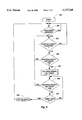
- FIG. 5 is a flow chart showing particular steps carried out by the embodiment of the present invention described herein.
- FIG. 6 is a flow chart showing the steps carried out by the embodiment of the present invention described herein to determine if the drag mode should be entered.
- FIG. 7 is a flow chart showing the steps carried out by the embodiment of the present invention described herein to determine if the user has moved the pointing object to a border of a touch sensitive pad.
- FIG. 8 is a flow chart showing the steps carried out by the embodiment of the present invention described herein to extend to drag mode beyond the edge of the position sensing surface.
- FIG. 2 is a block diagram representing one presently preferred embodiment of the present invention. It will be appreciated that the present invention may be embodied in specific forms other than those described herein. The described embodiments are, however, the those presently preferred for carrying out the present invention.
- a touch sensitive pointing device 100 which includes a touch pad 102 and an interface circuit 104.
- the touch pad 102 has a position sensing surface which senses the position of a pointing object 103, such as a stylus or a user's finger, which is manipulated by the user.
- the interface circuit 104 includes those components, whether embodied in software, firmware, or hardware, which are necessary to interpret the position information obtained from the touch pad 102 to industry standard signals understandable by the computer 112.
- the computer 112 may include a component or driver 114, for example a mouse driver, or some other cursor positioning utility to interpret the signals received from the touch pad 102. Alternatively, those skilled in the art can arrive at many other techniques for the touch pad to communicate with the computer 112.
- the touch sensitive pointing device which is described in U.S. Pat. No. 5,305,017 be used with the present invention.
- the touch sensitive pointing device described in U.S. Pat. No. 5,305,017 is particularly advantageous in that the cursor positioning, clicking, and dragging functions can all be accurately carried out by a user using only a single finger as a pointing object.
- Other advantages of the touch sensitive pointing device described in U.S. Pat. No. 5,305,017 are described therein or will be apparent from use of the invention.
- U.S. Pat. No. 5,305,017 is now incorporated herein by reference in its entirety. Using the information set forth in U.S. Pat. No. 5,305,017 and the information set forth herein, a system for carrying out the present invention can be readily arrived at by those skilled in the art. Importantly, the present invention is readily adaptable for use with numerous other pointing devices such as those mentioned earlier
- the touch sensitive pointing device 100 of the present invention is connected to the computer 112.
- the computer 112 is connected to a display 116 upon which various text and other objects are displayed and a cursor is located.
- the components of the interface circuit 104 will be described shortly.
- FIG. 3A is a representation of the touch pad 102 which has four edges 121A-D which will be referred to herein as a top edge 121A, a right edge 121B, a bottom edge 121C, and a left edge 121D. While the represented touch pad 102 is preferred for use with the present invention, it will be appreciated that touch pads of different shapes and configurations can also be used. Moreover, other cursor locating devices, such as tablets and those exemplary devices mentioned earlier, also benefit from the present invention.
- the touch pad 102 serves as a relative cursor locating device. Illustrated in the display 116 are three cursor positions a, b & c. Cursor position a represents a beginning cursor location. Cursor position c represents a desired ending cursor location. On the touch pad 102 location a represents the beginning position of a pointing object, such as a stylus or a user's finger, and the position where the user begins the drag operation intending to move text or other object to the desired location c on the display.
- a pointing object such as a stylus or a user's finger
- the touch pad is being used as a relative cursor positioning device, disadvantageously, when the user moves the pointing object to position b at the right edge 121B of the touch pad 102, the cursor has only reached corresponding location b on the display 116. The user must then lift the pointing object from the surface of the touch pad 102, which without the present invention, would cause the drag operation to terminate. In some instances, lifting the pointing object would even cause the cursor to snap back to the beginning position a. It is to be understood that even though a pointing object is not explicitly represented in FIGS. 3A-C, the pointing object may be a user's finger or any other appropriate object.
- FIG. 3B is a further representation of the touch pad 102.
- border areas 120A-D are defined adjacent to each edge 121A-D of the touch pad 102.
- the respective limits of the border areas 120A-D are represented by the lines 122A-D.
- any position on the touch pad 102 can be defined by an x,y coordinate, with both values expressed as positive values as suggested in FIG. 3B.
- the touch pad 102 of the present invention also provide a vertical z component to determine if the pointing object is present on the surface of the touch pad 102.
- the present invention utilize the pointing object making appropriate "taps" on the surface of the touch pad 102 to invoke the click and drag functions which must be provided.
- Obtaining z position information which can be used to carry out such "tap” functions is described in U.S. Pat. No. 5,305,017 but alternative methods, such as mechanical or touch sensitive buttons, can be used within the scope of the present invention to access the click and drag functions.
- FIG. 3C is a representation of the touch pad 102 and the display 116 with a preferred embodiment of the present invention operating therewith.
- the user when a user desires to move the cursor from position a to position c on the display 116, the user begins the movement of the pointing object on the touch pad 102 at location a on the touch pad 102 by engaging the drag mode. As the user moves the pointing object to position b within boundary 102B, the drag mode is maintained (which causes the cursor to be held at position b on the display 116) while the user lifts the pointing object from the surface of the touch pad 102.
- the user moves the pointing object to a new position on the surface of the touch pad 102, for example to position b new , and continues to stroke the touch pad 102 in the desired direction.
- the cursor which was held at position b on the display 116, now continues to move to the desired cursor position c on the display 116.
- the user releases the drag function as explained earlier. Releasing the drag function can, for example, cause the text or object (not represented in FIG. 3C) to be dropped at position c.
- the present invention allows the user to reposition the pointing object anywhere on the touch pad 102, including within the borders 120A-D, and continue the drag operation in any direction. Moreover, the present invention will allow a user to utilize multiple strokes across the touch pad 102 while maintaining the drag mode each time a border 120A-D is entered.
- the output of the touch sensitive pointing device 100 is scaled to require many strokes across the surface of the touch pad 102 to cross the display 116 (in order to provide very accurate cursor locating) the user can repeatedly stroke the touch pad while the drag mode is engaged without interruption as the cursor slowly moves across the display 116. Still further, when working with documents or spread sheets so large that only a small portion can be windowed on the display 116 at one time, the present invention's feature of allowing multiple strokes across the touch pad 102 while maintaining the drag mode is a great benefit.
- the present invention advantageously allows a user to extend the drag function of a computer pointing device in a manner not previously known or suggested.
- the present invention allows the user to extend the drag function easily, conveniently, and without requiring long practice or accustomization to the method or apparatus.
- FIG. 4 is a flow chart showing the principle steps carried out in accordance with the present invention.
- the flow chart of FIG. 4 starts at 150 and illustrates one preferred method of the present invention.
- a border area is defined at step 152.
- the touch pad (102 FIGS. 3A-C) and associated structures detect when the pointing object is within the border (120A-D). It will be appreciated that those skilled in the art can arrive at many different methods and structures to determine when the pointing object is on, near, or in the border.
- step 156 it is determined if the drag function is engaged. If the drag function is engaged (step 156), and the pointing object is within the border (step 154), in accordance with the present invention and as shown at step 158, the drag mode is maintained and the cursor is held at a first location.
- the first location is the location of the cursor on the display when the pointing object was lifted off from the touch pad 102.
- the drag mode is maintained and the cursor is held at the first position on the display (116 in FIGS. 3A-C) while the user moves the pointing object to another position on the touch pad 102.
- the drag function continues so that the cursor continues to move on the display 116 as the user moves the pointing object from the new position on the touch pad 102 to an end position.
- the end position corresponds to the desired location of the cursor on the display 116.
- any method or structure which functions to hold the cursor in a location on a real-time display while the user repositions a pointing object to another position on a position sensing surface and then allows the cursor movement to continue from the location on the display as the user continues movement of the pointing object, all while maintaining the drag mode, is intended to fall within the scope of the present invention.
- FIGS. 5-8 provide further information regarding preferred embodiments of the present invention. Using the information set forth herein, those skilled in the art will be able to readily arrive at many different arrangements of software, firmware, and/or hardware which will carry out the present invention.
- the border limits (122A-D in FIG. 3B) are initialized. Desirably, the positions of border limits (122A-D) can be altered by the user and each of the border limits (122A-D) can be initialized differently by the user. Importantly, it is within the scope of the present invention to size and position the borders (120A-D in FIG. 3B) anywhere on the touch pad (116 in FIG. 3B) to create a border of any shape or size in accordance with the needs and desires of the user.
- the method waits in a loop until position information is available from the touch pad (102 in FIGS. 3A-C) or other position sensing device. If position information is available from the touch pad 102, at step 168 the x, y, z position information is processed.
- the click and drag functions be invoked by the user tapping on the surface of the touch pad 102.
- the present invention allows a user to tap once to invoke a click function, tap twice to invoke a double click function, and tap once immediately followed by holding the pointing object against the surface of the touch pad (102 in FIGS. 3A-C) to invoke the drag function. If the user lifts the pointing object off the touch pad (102 in FIGS.
- step 170 whether the drag mode is engaged is determined. Further information regarding the steps used to determine if the drag mode is engaged and whether the drag mode should continue is set forth in FIG. 6 which will be discussed shortly.
- the method next determines if the pointing object is in the border (120A-C in FIG. 3B) as will be further discussed in connection with FIG. 7.
- the drag extend mode is activated as will be further discussed in connection with FIG. 8.
- the x, y, z and button information is sent to the computer 116 for processing, for example by a mouse driver 114 which is resident in the computer 112. The method then loops back to step 166 and continues processing.
- the method determines at step 180 if a pointing object is on the touch pad (102 in FIGS. 3A-C). If a pointing object is on the touch pad 102, a timer is set at step 182. The length of the timer can beneficially be altered by the user to accommodate different preferences.
- the method determines if the pointing object is off the touch pad 102. If the pointing object is not off the touch pad 102, the method proceeds to step 190 and it is determined if the pointing object moved on the touch pad 102.
- the method determines if the timer has timed out at step 192. If the timer has timed out at step 192, the method returns to step 184; If the timer has not timed out at step 192, the method proceeds to step 200 where a button up signal is set. Also, if the pointing object moved at step 190, the method also proceeds to step 200 where a button up signal is set.
- the method determines whether a pointing object is on the touch pad (102 in FIGS. 3A-C). If the pointing object is on the touch pad 102, the method determines if the timer (step 188) has timed out at step 198; If the timer has not timed out at step 198 the method loops back to step 196. The method proceeds to step 200 if the timer (step 188) has timed out.
- step 196 If at step 196 it is determined that the pointing object is on the touch pad (102 in FIGS. 3A-C), the method proceeds to step 202 and sets a timer. After step 202, the method proceeds to step 204 and determines if the pointing object is off the touch pad 102 and if so, the method sets a button up signal (step 214), proceeds through a set button down routine (step 216), and then proceeds to step 200 and sets a button up signal.
- step 204 determines if the pointing object is not off the touch pad (102 in FIGS. 3A-C). If at step 204 it is determined that the pointing object is not off the touch pad (102 in FIGS. 3A-C), the method proceeds to step 206 and determines if the timer set in step 202 has timed out. If the timer has not timed out at step 206, the method loops back to step 204. If the timer has timed out at step 206, the method proceeds to step 208 and the method engages the drag mode. At step 210 the method determines if the pointing object is off the touch pad 102. If the pointing object is not off the touch pad 102, the method waits in a loop at step 210.
- step 212 a set no drag routine is executed followed by step 200 which sets a button up signal. From step 200, the method again determines if the pointing object is off the touch pad 102. If the pointing object is not off the touch pad 102, the method waits by looping back on step 194. If the pointing object is off the touch pad 102 the method returns back to step 180.
- the foregoing method provides that the user can conveniently perform click functions and engage the drag function using taps with a single finger or with another appropriate pointing object.
- the present invention provides the signals which are required by an industry standard mouse driver (114 in FIG. 2) and can emulate a mouse device.
- the present invention can also communicate with the computer (112 in FIG. 2) in a variety of other ways which are now available or which may become available in the future.
- the present invention also most preferably allows the user to engage the drag mode, as well as perform clicking operations, without pushing any buttons. Still, the present invention provides advantages not previously available with a touch sensitive pointing device, regardless of whether buttons must or need not be used to invoke and engage the click and drag functions.
- FIG. 7 is a flow chart illustrating the preferred method of the present invention to determine if the pointing object is within a border (120A-D in FIG. 3B) as mentioned earlier at step 172 of FIG. 5.
- the method determines if the drag mode is engaged at step 232. If the drag mode is not engaged, a set not at edge flag routine is performed at step 242 and the method exits at step 248.
- the method determines if the x position of the pointing object is less than the left limit 122D (step 234), if the y position of the pointing object is greater than the bottom limit 122C (step 236), if the x position of the pointing object is greater than the right limit 122B (step 238), or the y position of the pointing object is less than the top limit 122A, then the method proceeds to step 244 and an at edge flag is set and the method exits at step 248.
- step 234 determines that the x position of the pointing object is not less than the left limit 122D (step 234), if the y position of the pointing object is not greater than the bottom limit 122C (step 236), if the x position of the pointing object is not greater than the right limit 122B (step 238), or the y position of the pointing object is not less than the top limit 122A, then the method proceeds to step 246 and a not at edge flag is set and the method exits at step 248. In the described fashion, the method of the present invention efficiently determines if the pointing object is in a border.
- FIG. 8 is a flow chart illustrating the preferred method to extend the drag mode beyond the edge of the position sensing surface of the touch sensitive pointing device 100 and is an example of the drag extend routine indicted at step 174 in FIG. 5.
- the method first determines if the drag mode is engaged at step 252. If the drag mode is not engaged, the method waits in a loop at step 252. If the drag mode is engaged, the method next determines if the pointing object is in the border (120A-D in FIG. 3B). If the pointing object is not in the border, the method returns to step 252.
- the method determines if the pointing object is off the touch pad 102 at step 256. If the pointing object is not off the touch pad 102, the method returns to step 254. If the pointing object is off the touch pad at step 256, the method proceeds to step 258 where a drag signal is set and a timer is set. It is presently preferred that the timer be set for a period of two seconds but it is preferred that the time be adjustable to meet the desires of the user.
- the periods of all of the timers described in connection with FIGS. 6-8 be user adjustable.
- the period of the timer set at step 258 determines how long a use will have to move the pointing object from one of the borders 120A-D to a new position on the touch pad 102 as explained in connection with FIG. 3C.
- the method determines if the pointing object is on the touch pad 102 and, if so, the method returns to step 254. If it is determined at step 260 that the pointing object is not on the touch pad 102, the method proceeds to step 262 where it is determined if the timer (step 258) has timed out. If the timer has not timed out at step 262, the method returns to step 260. If the timer has timed out at step 262, the method proceeds to step 264 and a no drag signal is set at step 264 and the method returns to step 252.
- FIG. 2 is a block diagram representing one presently preferred system of the present invention. From the forgoing description, it will be appreciated that the method of the present invention can be embodied in many different apparatus and systems. Depending upon the application to which the present invention is to be employed, the present invention may be embodied as software, firmware, hardware, or a combination of the foregoing.
- a position detection means which performs the functions necessary to use the touch pad.
- structures which carry out the present invention in cooperation with the position sensing structures.
- Shown in FIG. 2 at 106 is a means for detecting when the pointing device is on the edge of the border or beyond. Also represented at 108 is a means for activating a drag function. Represented at 110 in FIG. 2 is a means for maintaining the drag mode and holding the cursor at a first location on the display. Also depicted in FIG. 2 at 109 is a means for continuing the dragging function from the first location on the display to a second location on the display.
- the described structures can be embodied in many different forms, for example in a single integrated circuit. It is to be understood that any structures performing functions equivalent to the methods of the present invention are to be considered within the scope of the system of the present invention.
- the present invention provides a system and method for extending the drag function of computer pointing device which is reliable and easy to use.
- the present invention also provides a system and method for extending the drag function of a computer pointing device which is particularly adapted for use with a touch sensitive pointing device and which can operate with a user's finger as the only pointing object.
Abstract
Description
Claims (20)
Priority Applications (5)
| Application Number | Priority Date | Filing Date | Title |
|---|---|---|---|
| US08/413,199 US5757368A (en) | 1995-03-27 | 1995-03-27 | System and method for extending the drag function of a computer pointing device |
| DE19681316T DE19681316T1 (en) | 1995-03-27 | 1996-03-27 | Drag extension system |
| PCT/US1996/004244 WO1996030890A1 (en) | 1995-03-27 | 1996-03-27 | System for extending the drag function |
| JP52963996A JP3833709B2 (en) | 1995-03-27 | 1996-03-27 | Drag function expansion system |
| AU53768/96A AU5376896A (en) | 1995-03-27 | 1996-03-27 | System for extending the drag function |
Applications Claiming Priority (1)
| Application Number | Priority Date | Filing Date | Title |
|---|---|---|---|
| US08/413,199 US5757368A (en) | 1995-03-27 | 1995-03-27 | System and method for extending the drag function of a computer pointing device |
Publications (1)
| Publication Number | Publication Date |
|---|---|
| US5757368A true US5757368A (en) | 1998-05-26 |
Family
ID=23636266
Family Applications (1)
| Application Number | Title | Priority Date | Filing Date |
|---|---|---|---|
| US08/413,199 Expired - Lifetime US5757368A (en) | 1995-03-27 | 1995-03-27 | System and method for extending the drag function of a computer pointing device |
Country Status (5)
| Country | Link |
|---|---|
| US (1) | US5757368A (en) |
| JP (1) | JP3833709B2 (en) |
| AU (1) | AU5376896A (en) |
| DE (1) | DE19681316T1 (en) |
| WO (1) | WO1996030890A1 (en) |
Cited By (141)
| Publication number | Priority date | Publication date | Assignee | Title |
|---|---|---|---|---|
| US5903229A (en) * | 1996-02-20 | 1999-05-11 | Sharp Kabushiki Kaisha | Jog dial emulation input device |
| US5910802A (en) * | 1997-06-11 | 1999-06-08 | Microsoft Corporation | Operating system for handheld computing device having taskbar auto hide |
| EP0996052A2 (en) * | 1998-10-19 | 2000-04-26 | Fujitsu Limited | Input processing method and input control apparatus |
| US6188391B1 (en) | 1998-07-09 | 2001-02-13 | Synaptics, Inc. | Two-layer capacitive touchpad and method of making same |
| KR20010046646A (en) * | 1999-11-15 | 2001-06-15 | 차종근 | Touch-Pad Operating Mouse Button |
| US6334088B1 (en) * | 1999-05-14 | 2001-12-25 | Denso Corporation | Map display system having HTML information browser function |
| US6380931B1 (en) * | 1992-06-08 | 2002-04-30 | Synaptics Incorporated | Object position detector with edge motion feature and gesture recognition |
| US20030043113A1 (en) * | 2001-09-04 | 2003-03-06 | Alps Electric Co., Ltd. | Coordinates input apparatus having divided coordinates input surface |
| US6727892B1 (en) | 1999-05-20 | 2004-04-27 | Micron Technology, Inc. | Method of facilitating the selection of features at edges of computer touch screens |
| US6757002B1 (en) | 1999-11-04 | 2004-06-29 | Hewlett-Packard Development Company, L.P. | Track pad pointing device with areas of specialized function |
| US20050030048A1 (en) * | 2003-08-05 | 2005-02-10 | Bolender Robert J. | Capacitive sensing device for use in a keypad assembly |
| US6867790B1 (en) * | 1996-08-09 | 2005-03-15 | International Business Machines Corporation | Method and apparatus to conditionally constrain pointer movement on a computer display using visual cues, controlled pointer speed and barriers on the display which stop or restrict pointer movement |
| US20050197186A1 (en) * | 2004-03-05 | 2005-09-08 | Nintendo Co., Ltd. | Game program |
| US20050283727A1 (en) * | 2004-06-21 | 2005-12-22 | Large William T | Non-resident methods and systems for providing clickless user actuation of a webpage |
| US20060007174A1 (en) * | 2004-07-06 | 2006-01-12 | Chung-Yi Shen | Touch control method for a drag gesture and control module thereof |
| US20060019752A1 (en) * | 2004-07-26 | 2006-01-26 | Nintendo Co., Ltd. | Storage medium having game program stored thereon, game apparatus and input device |
| US20060019753A1 (en) * | 2004-07-26 | 2006-01-26 | Nintendo Co., Ltd. | Storage medium having game program stored thereon, game apparatus, input device, and storage medium having program stored thereon |
| US20060033721A1 (en) * | 2004-04-23 | 2006-02-16 | Richard Woolley | Method for scrolling and edge motion on a touchpad |
| US20060061595A1 (en) * | 2002-05-31 | 2006-03-23 | Goede Patricia A | System and method for visual annotation and knowledge representation |
| US20070032967A1 (en) * | 2005-07-18 | 2007-02-08 | Analog Devices, Inc. | Automatic environmental compensation of capacitance based proximity sensors |
| US20070050726A1 (en) * | 2005-08-26 | 2007-03-01 | Masanori Wakai | Information processing apparatus and processing method of drag object on the apparatus |
| US20070097096A1 (en) * | 2006-03-25 | 2007-05-03 | Outland Research, Llc | Bimodal user interface paradigm for touch screen devices |
| US20070176906A1 (en) * | 2006-02-01 | 2007-08-02 | Synaptics Incorporated | Proximity sensor and method for indicating extended interface results |
| US20070176903A1 (en) * | 2006-01-31 | 2007-08-02 | Dahlin Jeffrey J | Capacitive touch sensor button activation |
| US7253643B1 (en) | 2006-07-19 | 2007-08-07 | Cypress Semiconductor Corporation | Uninterrupted radial capacitive sense interface |
| US20070247440A1 (en) * | 2006-04-24 | 2007-10-25 | Sang Hyun Shin | Touch screen device and method of displaying images thereon |
| US20070273666A1 (en) * | 2006-05-24 | 2007-11-29 | Sang Hyun Shin | Touch screen device and operating method thereof |
| US20070277124A1 (en) * | 2006-05-24 | 2007-11-29 | Sang Hyun Shin | Touch screen device and operating method thereof |
| US20070273669A1 (en) * | 2006-05-24 | 2007-11-29 | Lg Electronics Inc. | Touch screen device and operating method thereof |
| US20070277126A1 (en) * | 2006-05-24 | 2007-11-29 | Ho Joo Park | Touch screen device and method of selecting files thereon |
| US20070273665A1 (en) * | 2006-05-24 | 2007-11-29 | Lg Electronics Inc. | Touch screen device and operating method thereof |
| US7304638B2 (en) * | 1999-05-20 | 2007-12-04 | Micron Technology, Inc. | Computer touch screen adapted to facilitate selection of features at edge of screen |
| US7307485B1 (en) | 2005-11-14 | 2007-12-11 | Cypress Semiconductor Corporation | Capacitance sensor using relaxation oscillators |
| US7312616B2 (en) | 2006-01-20 | 2007-12-25 | Cypress Semiconductor Corporation | Successive approximate capacitance measurement circuit |
| US20080024455A1 (en) * | 2006-07-25 | 2008-01-31 | Lee Mark R | Technique for increasing the sensitivity of capacitive sensor arrays |
| US20080313568A1 (en) * | 2007-06-12 | 2008-12-18 | Samsung Electronics Co., Ltd. | Digital multimedia playback apparatus and control method thereof |
| US20090213086A1 (en) * | 2006-04-19 | 2009-08-27 | Ji Suk Chae | Touch screen device and operating method thereof |
| US20100066705A1 (en) * | 2000-11-10 | 2010-03-18 | Microsoft Corporation | Highlevel active pen matrix |
| US20100107116A1 (en) * | 2008-10-27 | 2010-04-29 | Nokia Corporation | Input on touch user interfaces |
| US20100105443A1 (en) * | 2008-10-27 | 2010-04-29 | Nokia Corporation | Methods and apparatuses for facilitating interaction with touch screen apparatuses |
| US7721609B2 (en) | 2006-03-31 | 2010-05-25 | Cypress Semiconductor Corporation | Method and apparatus for sensing the force with which a button is pressed |
| US7737724B2 (en) | 2007-04-17 | 2010-06-15 | Cypress Semiconductor Corporation | Universal digital block interconnection and channel routing |
| US7737958B2 (en) | 2006-04-19 | 2010-06-15 | Lg Electronics Inc. | Touch screen device and method of displaying and selecting menus thereof |
| US7761845B1 (en) | 2002-09-09 | 2010-07-20 | Cypress Semiconductor Corporation | Method for parameterizing a user module |
| US7765095B1 (en) | 2000-10-26 | 2010-07-27 | Cypress Semiconductor Corporation | Conditional branching in an in-circuit emulation system |
| US7770113B1 (en) | 2001-11-19 | 2010-08-03 | Cypress Semiconductor Corporation | System and method for dynamically generating a configuration datasheet |
| US7774190B1 (en) | 2001-11-19 | 2010-08-10 | Cypress Semiconductor Corporation | Sleep and stall in an in-circuit emulation system |
| US7825688B1 (en) | 2000-10-26 | 2010-11-02 | Cypress Semiconductor Corporation | Programmable microcontroller architecture(mixed analog/digital) |
| US7844437B1 (en) | 2001-11-19 | 2010-11-30 | Cypress Semiconductor Corporation | System and method for performing next placements and pruning of disallowed placements for programming an integrated circuit |
| US20100318930A1 (en) * | 2006-02-10 | 2010-12-16 | Microsoft Corporation | Assisting user interface element use |
| US7893724B2 (en) | 2004-03-25 | 2011-02-22 | Cypress Semiconductor Corporation | Method and circuit for rapid alignment of signals |
| US20110157005A1 (en) * | 2009-12-24 | 2011-06-30 | Brother Kogyo Kabushiki Kaisha | Head-mounted display |
| US20110163970A1 (en) * | 2010-01-06 | 2011-07-07 | Lemay Stephen O | Device, Method, and Graphical User Interface for Manipulating Information Items in Folders |
| US20110187657A1 (en) * | 2010-02-04 | 2011-08-04 | Ian Robert Knowles | Touch sensitive screen for scrolling through sets of data |
| US20110221692A1 (en) * | 2010-03-11 | 2011-09-15 | Parrot | Method and an appliance for remotely controlling a drone, in particular a rotary wing drone |
| US8026739B2 (en) | 2007-04-17 | 2011-09-27 | Cypress Semiconductor Corporation | System level interconnect with programmable switching |
| US8040142B1 (en) | 2006-03-31 | 2011-10-18 | Cypress Semiconductor Corporation | Touch detection techniques for capacitive touch sense systems |
| US8040321B2 (en) | 2006-07-10 | 2011-10-18 | Cypress Semiconductor Corporation | Touch-sensor with shared capacitive sensors |
| US8040266B2 (en) | 2007-04-17 | 2011-10-18 | Cypress Semiconductor Corporation | Programmable sigma-delta analog-to-digital converter |
| US8049569B1 (en) | 2007-09-05 | 2011-11-01 | Cypress Semiconductor Corporation | Circuit and method for improving the accuracy of a crystal-less oscillator having dual-frequency modes |
| US8058937B2 (en) | 2007-01-30 | 2011-11-15 | Cypress Semiconductor Corporation | Setting a discharge rate and a charge rate of a relaxation oscillator circuit |
| US8069405B1 (en) | 2001-11-19 | 2011-11-29 | Cypress Semiconductor Corporation | User interface for efficiently browsing an electronic document using data-driven tabs |
| US8069428B1 (en) | 2001-10-24 | 2011-11-29 | Cypress Semiconductor Corporation | Techniques for generating microcontroller configuration information |
| US8069436B2 (en) | 2004-08-13 | 2011-11-29 | Cypress Semiconductor Corporation | Providing hardware independence to automate code generation of processing device firmware |
| US8067948B2 (en) | 2006-03-27 | 2011-11-29 | Cypress Semiconductor Corporation | Input/output multiplexer bus |
| US8078894B1 (en) | 2007-04-25 | 2011-12-13 | Cypress Semiconductor Corporation | Power management architecture, method and configuration system |
| US8078970B1 (en) | 2001-11-09 | 2011-12-13 | Cypress Semiconductor Corporation | Graphical user interface with user-selectable list-box |
| US8086417B2 (en) | 2007-07-03 | 2011-12-27 | Cypress Semiconductor Corporation | Normalizing capacitive sensor array signals |
| US8085100B2 (en) | 2005-02-04 | 2011-12-27 | Cypress Semiconductor Corporation | Poly-phase frequency synthesis oscillator |
| US8085067B1 (en) | 2005-12-21 | 2011-12-27 | Cypress Semiconductor Corporation | Differential-to-single ended signal converter circuit and method |
| US8089461B2 (en) | 2005-06-23 | 2012-01-03 | Cypress Semiconductor Corporation | Touch wake for electronic devices |
| US8089472B2 (en) | 2006-05-26 | 2012-01-03 | Cypress Semiconductor Corporation | Bidirectional slider with delete function |
| US8089288B1 (en) | 2006-11-16 | 2012-01-03 | Cypress Semiconductor Corporation | Charge accumulation capacitance sensor with linear transfer characteristic |
| US8089289B1 (en) | 2007-07-03 | 2012-01-03 | Cypress Semiconductor Corporation | Capacitive field sensor with sigma-delta modulator |
| US8092083B2 (en) | 2007-04-17 | 2012-01-10 | Cypress Semiconductor Corporation | Temperature sensor with digital bandgap |
| US20120011438A1 (en) * | 2010-07-12 | 2012-01-12 | Lg Electronics Inc. | Mobile terminal and controlling method thereof |
| US8103497B1 (en) | 2002-03-28 | 2012-01-24 | Cypress Semiconductor Corporation | External interface for event architecture |
| US8103496B1 (en) | 2000-10-26 | 2012-01-24 | Cypress Semicondutor Corporation | Breakpoint control in an in-circuit emulation system |
| US8120408B1 (en) | 2005-05-05 | 2012-02-21 | Cypress Semiconductor Corporation | Voltage controlled oscillator delay cell and method |
| US8130025B2 (en) | 2007-04-17 | 2012-03-06 | Cypress Semiconductor Corporation | Numerical band gap |
| US8144126B2 (en) | 2007-05-07 | 2012-03-27 | Cypress Semiconductor Corporation | Reducing sleep current in a capacitance sensing system |
| US8149048B1 (en) | 2000-10-26 | 2012-04-03 | Cypress Semiconductor Corporation | Apparatus and method for programmable power management in a programmable analog circuit block |
| US20120086726A1 (en) * | 2002-09-30 | 2012-04-12 | Canon Kabushiki Kaisha | Image editing method, image editing apparatus, program for implementing image editing method, and recording medium recording program |
| US8160864B1 (en) | 2000-10-26 | 2012-04-17 | Cypress Semiconductor Corporation | In-circuit emulator and pod synchronized boot |
| US8169238B1 (en) | 2007-07-03 | 2012-05-01 | Cypress Semiconductor Corporation | Capacitance to frequency converter |
| US8176296B2 (en) | 2000-10-26 | 2012-05-08 | Cypress Semiconductor Corporation | Programmable microcontroller architecture |
| US20120192094A1 (en) * | 2002-12-10 | 2012-07-26 | Neonode, Inc. | User interface |
| CN101563667B (en) * | 2006-10-26 | 2012-09-19 | 苹果公司 | Method and equipment for adjusting an insertion point marker |
| US8286125B2 (en) | 2004-08-13 | 2012-10-09 | Cypress Semiconductor Corporation | Model for a hardware device-independent method of defining embedded firmware for programmable systems |
| US8321174B1 (en) | 2008-09-26 | 2012-11-27 | Cypress Semiconductor Corporation | System and method to measure capacitance of capacitive sensor array |
| US20120306781A1 (en) * | 2011-05-31 | 2012-12-06 | Lg Electronics Inc. | Mobile device and control method for a mobile device |
| US20120319971A1 (en) * | 2011-06-17 | 2012-12-20 | Konica Minolta Business Technologies, Inc. | Information viewing apparatus, control program and controlling method |
| US8358142B2 (en) | 2008-02-27 | 2013-01-22 | Cypress Semiconductor Corporation | Methods and circuits for measuring mutual and self capacitance |
| US8402313B1 (en) | 2002-05-01 | 2013-03-19 | Cypress Semiconductor Corporation | Reconfigurable testing system and method |
| US8487912B1 (en) | 2008-02-01 | 2013-07-16 | Cypress Semiconductor Corporation | Capacitive sense touch device with hysteresis threshold |
| US8487639B1 (en) | 2008-11-21 | 2013-07-16 | Cypress Semiconductor Corporation | Receive demodulator for capacitive sensing |
| US20130185665A1 (en) * | 2012-01-16 | 2013-07-18 | Konica Minolta Business Technologies, Inc. | Image forming apparatus |
| US8493351B2 (en) | 2006-03-30 | 2013-07-23 | Cypress Semiconductor Corporation | Apparatus and method for reducing average scan rate to detect a conductive object on a sensing device |
| US8499270B1 (en) | 2007-04-25 | 2013-07-30 | Cypress Semiconductor Corporation | Configuration of programmable IC design elements |
| US8516025B2 (en) | 2007-04-17 | 2013-08-20 | Cypress Semiconductor Corporation | Clock driven dynamic datapath chaining |
| US8525798B2 (en) | 2008-01-28 | 2013-09-03 | Cypress Semiconductor Corporation | Touch sensing |
| US8527949B1 (en) | 2001-11-19 | 2013-09-03 | Cypress Semiconductor Corporation | Graphical user interface for dynamically reconfiguring a programmable device |
| US8537121B2 (en) | 2006-05-26 | 2013-09-17 | Cypress Semiconductor Corporation | Multi-function slider in touchpad |
| US8564313B1 (en) | 2007-07-03 | 2013-10-22 | Cypress Semiconductor Corporation | Capacitive field sensor with sigma-delta modulator |
| US8570052B1 (en) | 2008-02-27 | 2013-10-29 | Cypress Semiconductor Corporation | Methods and circuits for measuring mutual and self capacitance |
| US20130293510A1 (en) * | 2012-05-07 | 2013-11-07 | Cirque Corporation | Method for distinguishing between edge swipe gestures that enter a touch sensor from an edge and other similar but non-edge swipe actions |
| US20140118281A1 (en) * | 2012-10-26 | 2014-05-01 | Cirque Corporation | DETERMINING WHAT INPUT TO ACCEPT BY A TOUCH SENSOR AFTER INTENTIONAL AND ACCIDENTAL LIFT-OFF and SLIDE-OFF WHEN GESTURING OR PERFORMING A FUNCTION |
| US20140195969A1 (en) * | 2000-05-11 | 2014-07-10 | Nes Stewart Irvine | Zeroclick |
| US20140304826A1 (en) * | 2013-04-08 | 2014-10-09 | Cirque Corporation | Capacitive sensor integrated in an integrated circuit package |
| US8866500B2 (en) | 2009-03-26 | 2014-10-21 | Cypress Semiconductor Corporation | Multi-functional capacitance sensing circuit with a current conveyor |
| US20140380226A1 (en) * | 2013-06-21 | 2014-12-25 | Sharp Kabushiki Kaisha | Image display apparatus allowing operation of image screen and operation method thereof |
| US20150082250A1 (en) * | 2010-01-06 | 2015-03-19 | Apple Inc. | Device, Method, and Graphical User Interface for Navigating and Displaying Content in Context |
| US9047006B2 (en) | 2010-09-29 | 2015-06-02 | Sony Corporation | Electronic device system with information processing mechanism and method of operation thereof |
| USRE45559E1 (en) | 1997-10-28 | 2015-06-09 | Apple Inc. | Portable computers |
| US9104273B1 (en) | 2008-02-29 | 2015-08-11 | Cypress Semiconductor Corporation | Multi-touch sensing method |
| US9110578B2 (en) | 2004-06-28 | 2015-08-18 | Nokia Technologies Oy | Electronic device and method for providing extended user interface |
| US9152258B2 (en) | 2008-06-19 | 2015-10-06 | Neonode Inc. | User interface for a touch screen |
| US9154160B2 (en) | 2006-11-14 | 2015-10-06 | Cypress Semiconductor Corporation | Capacitance to code converter with sigma-delta modulator |
| US9268441B2 (en) | 2011-04-05 | 2016-02-23 | Parade Technologies, Ltd. | Active integrator for a capacitive sense array |
| US9417728B2 (en) | 2009-07-28 | 2016-08-16 | Parade Technologies, Ltd. | Predictive touch surface scanning |
| US9448964B2 (en) | 2009-05-04 | 2016-09-20 | Cypress Semiconductor Corporation | Autonomous control in a programmable system |
| US9500686B1 (en) | 2007-06-29 | 2016-11-22 | Cypress Semiconductor Corporation | Capacitance measurement system and methods |
| US9513791B2 (en) | 2010-09-29 | 2016-12-06 | Sony Corporation | Electronic device system with process continuation mechanism and method of operation thereof |
| US20170003852A1 (en) * | 2007-12-07 | 2017-01-05 | Sony Corporation | Information display terminal, information display method and program |
| US9564902B2 (en) | 2007-04-17 | 2017-02-07 | Cypress Semiconductor Corporation | Dynamically configurable and re-configurable data path |
| US20170147196A1 (en) * | 2008-05-19 | 2017-05-25 | Microsoft Technology Licensing, Llc | Accessing A Menu Utilizing A Drag-Operation |
| US9720805B1 (en) | 2007-04-25 | 2017-08-01 | Cypress Semiconductor Corporation | System and method for controlling a target device |
| US9766738B1 (en) | 2006-08-23 | 2017-09-19 | Cypress Semiconductor Corporation | Position and usage based prioritization for capacitance sense interface |
| US10073584B2 (en) | 2016-06-12 | 2018-09-11 | Apple Inc. | User interfaces for retrieving contextually relevant media content |
| US10324973B2 (en) | 2016-06-12 | 2019-06-18 | Apple Inc. | Knowledge graph metadata network based on notable moments |
| US10698662B2 (en) | 2001-11-15 | 2020-06-30 | Cypress Semiconductor Corporation | System providing automatic source code generation for personalization and parameterization of user modules |
| US10803135B2 (en) | 2018-09-11 | 2020-10-13 | Apple Inc. | Techniques for disambiguating clustered occurrence identifiers |
| US10846343B2 (en) | 2018-09-11 | 2020-11-24 | Apple Inc. | Techniques for disambiguating clustered location identifiers |
| US10904426B2 (en) | 2006-09-06 | 2021-01-26 | Apple Inc. | Portable electronic device for photo management |
| US11038718B2 (en) | 2016-01-27 | 2021-06-15 | Securrency, Inc. | Method, apparatus, and computer-readable medium for transaction management spanning multiple heterogeneous computing networks |
| US11086935B2 (en) | 2018-05-07 | 2021-08-10 | Apple Inc. | Smart updates from historical database changes |
| US11243996B2 (en) | 2018-05-07 | 2022-02-08 | Apple Inc. | Digital asset search user interface |
| US11307737B2 (en) | 2019-05-06 | 2022-04-19 | Apple Inc. | Media browsing user interface with intelligently selected representative media items |
| US11334209B2 (en) | 2016-06-12 | 2022-05-17 | Apple Inc. | User interfaces for retrieving contextually relevant media content |
| US11527329B2 (en) | 2020-07-28 | 2022-12-13 | Xifin, Inc. | Automatically determining a medical recommendation for a patient based on multiple medical images from multiple different medical imaging modalities |
| US11782575B2 (en) | 2018-05-07 | 2023-10-10 | Apple Inc. | User interfaces for sharing contextually relevant media content |
Families Citing this family (4)
| Publication number | Priority date | Publication date | Assignee | Title |
|---|---|---|---|---|
| US8645852B2 (en) | 2006-06-23 | 2014-02-04 | International Business Machines Corporation | Drag and drop quoting mechanism for use with discussion forums |
| WO2008038239A2 (en) * | 2006-09-29 | 2008-04-03 | Nxp B.V. | Processing a signal from a pointing device sensor |
| EP2184671B1 (en) * | 2008-10-29 | 2011-05-04 | Giga-Byte Communications, Inc. | Method and apparatus for switching touch screen of handheld electronic apparatus |
| WO2011037733A1 (en) * | 2009-09-25 | 2011-03-31 | Apple Inc. | Device, method, and graphical user interface using mid-drag gestures |
Citations (45)
| Publication number | Priority date | Publication date | Assignee | Title |
|---|---|---|---|---|
| US3857092A (en) * | 1972-03-22 | 1974-12-24 | H Meyer | Electrical length measuring system |
| US3886311A (en) * | 1972-05-16 | 1975-05-27 | Talos Systems | Electrical writing pen and sensor |
| US4032841A (en) * | 1975-11-28 | 1977-06-28 | A. P. C. Industries, Inc. | Method and apparatus for measuring the capacitance of telephone cable pairs |
| US4071691A (en) * | 1976-08-24 | 1978-01-31 | Peptek, Inc. | Human-machine interface apparatus |
| US4103252A (en) * | 1976-11-26 | 1978-07-25 | Xerox Corporation | Capacitive touch-activated transducer system including a plurality of oscillators |
| US4246452A (en) * | 1979-01-05 | 1981-01-20 | Mattel, Inc. | Switch apparatus |
| JPS56132028A (en) * | 1980-03-19 | 1981-10-16 | Casio Comput Co Ltd | Touch switch device |
| US4455452A (en) * | 1982-09-13 | 1984-06-19 | Touch Activated Switch Arrays, Inc. | Touch activated controller for generating X-Y output information |
| US4476463A (en) * | 1981-08-24 | 1984-10-09 | Interaction Systems, Inc. | Display device having unpatterned touch detection |
| US4495485A (en) * | 1980-12-12 | 1985-01-22 | General Electric Company | Touch control arrangement for data entry |
| JPS60192033A (en) * | 1984-01-17 | 1985-09-30 | Katsuyoshi Harada | Mud forced-feeding tank device |
| US4550221A (en) * | 1983-10-07 | 1985-10-29 | Scott Mabusth | Touch sensitive control device |
| JPS60241112A (en) * | 1984-05-11 | 1985-11-30 | アルフレツド・テヴエス・ゲーエムベーハー | Fluid control valve |
| US4587378A (en) * | 1984-07-30 | 1986-05-06 | Koala Technologies Corporation | Two-layer touch tablet |
| JPS61115118A (en) * | 1984-11-09 | 1986-06-02 | Hitachi Ltd | Information i/o display device |
| US4639720A (en) * | 1981-01-12 | 1987-01-27 | Harris Corporation | Electronic sketch pad |
| US4672154A (en) * | 1985-04-03 | 1987-06-09 | Kurta Corporation | Low power, high resolution digitizing system with cordless pen/mouse |
| US4680430A (en) * | 1984-02-29 | 1987-07-14 | Fujitsu Limited | Coordinate detecting apparatus |
| US4686332A (en) * | 1986-06-26 | 1987-08-11 | International Business Machines Corporation | Combined finger touch and stylus detection system for use on the viewing surface of a visual display device |
| US4698641A (en) * | 1985-08-08 | 1987-10-06 | Gte Sprint Communications Corp | Adjustment device for platform mounted horn antenna |
| US4700022A (en) * | 1983-12-26 | 1987-10-13 | Regie Nationale Des Usines Renault | Method and apparatus for determining the coordinates of a contact point on a resistive type semianalog sensitive surface |
| US4707845A (en) * | 1986-08-26 | 1987-11-17 | Tektronix, Inc. | Touch panel with automatic nulling |
| US4736191A (en) * | 1985-08-02 | 1988-04-05 | Karl E. Matzke | Touch activated control method and apparatus |
| US4740781A (en) * | 1985-02-08 | 1988-04-26 | Itt Gilfillan | Touch panel data entry device for thin film electroluminescent panels |
| US4743895A (en) * | 1984-04-05 | 1988-05-10 | Phosphor Products Co. Ltd. | Capacitive switches |
| EP0299204A2 (en) * | 1987-07-10 | 1989-01-18 | Euchner & Co. | Manually operable positioning device |
| US4922061A (en) * | 1988-06-13 | 1990-05-01 | Tektronix, Inc. | Capacitive touch panel system with randomly modulated position measurement signal |
| US4975830A (en) * | 1988-12-05 | 1990-12-04 | Dayna Communications, Inc. | Computer communication system having supplemental formats |
| WO1991003039A1 (en) * | 1989-08-16 | 1991-03-07 | Gerpheide George E | Methods and apparatus for data input |
| US5196838A (en) * | 1990-12-28 | 1993-03-23 | Apple Computer, Inc. | Intelligent scrolling |
| US5252951A (en) * | 1989-04-28 | 1993-10-12 | International Business Machines Corporation | Graphical user interface with gesture recognition in a multiapplication environment |
| US5305017A (en) * | 1989-08-16 | 1994-04-19 | Gerpheide George E | Methods and apparatus for data input |
| US5309555A (en) * | 1990-05-15 | 1994-05-03 | International Business Machines Corporation | Realtime communication of hand drawn images in a multiprogramming window environment |
| US5327161A (en) * | 1989-08-09 | 1994-07-05 | Microtouch Systems, Inc. | System and method for emulating a mouse input device with a touchpad input device |
| US5333247A (en) * | 1988-06-10 | 1994-07-26 | International Business Machines Corporation | Scrolling tool for text and graphics in a display system |
| US5349303A (en) * | 1993-07-02 | 1994-09-20 | Cirque Corporation | Electrical charge transfer apparatus |
| US5406307A (en) * | 1989-12-05 | 1995-04-11 | Sony Corporation | Data processing apparatus having simplified icon display |
| US5422993A (en) * | 1991-12-17 | 1995-06-06 | International Business Machines Corporation | Method and system for performing direct manipulation operations in a computer system |
| US5485174A (en) * | 1990-12-31 | 1996-01-16 | International Business Machines Corporation | Display image scroll control and method |
| US5491495A (en) * | 1990-11-13 | 1996-02-13 | Wang Laboratories, Inc. | User interface having simulated devices |
| US5495566A (en) * | 1994-11-22 | 1996-02-27 | Microsoft Corporation | Scrolling contents of a window |
| US5506951A (en) * | 1994-03-01 | 1996-04-09 | Ishikawa; Hiroshi | Scroll bar with jump tags |
| US5528260A (en) * | 1994-12-22 | 1996-06-18 | Autodesk, Inc. | Method and apparatus for proportional auto-scrolling |
| US5530865A (en) * | 1993-03-03 | 1996-06-25 | Apple Computer, Inc. | Method and apparatus for improved application program switching on a computer-controlled display system |
| US5543590A (en) * | 1992-06-08 | 1996-08-06 | Synaptics, Incorporated | Object position detector with edge motion feature |
Family Cites Families (1)
| Publication number | Priority date | Publication date | Assignee | Title |
|---|---|---|---|---|
| US5164713A (en) * | 1991-10-15 | 1992-11-17 | Bain Lee L | Cursor position controller for use with mouse and display systems |
-
1995
- 1995-03-27 US US08/413,199 patent/US5757368A/en not_active Expired - Lifetime
-
1996
- 1996-03-27 DE DE19681316T patent/DE19681316T1/en not_active Ceased
- 1996-03-27 WO PCT/US1996/004244 patent/WO1996030890A1/en active Application Filing
- 1996-03-27 JP JP52963996A patent/JP3833709B2/en not_active Expired - Fee Related
- 1996-03-27 AU AU53768/96A patent/AU5376896A/en not_active Abandoned
Patent Citations (46)
| Publication number | Priority date | Publication date | Assignee | Title |
|---|---|---|---|---|
| US3857092A (en) * | 1972-03-22 | 1974-12-24 | H Meyer | Electrical length measuring system |
| US3886311A (en) * | 1972-05-16 | 1975-05-27 | Talos Systems | Electrical writing pen and sensor |
| US4032841A (en) * | 1975-11-28 | 1977-06-28 | A. P. C. Industries, Inc. | Method and apparatus for measuring the capacitance of telephone cable pairs |
| US4071691A (en) * | 1976-08-24 | 1978-01-31 | Peptek, Inc. | Human-machine interface apparatus |
| US4103252A (en) * | 1976-11-26 | 1978-07-25 | Xerox Corporation | Capacitive touch-activated transducer system including a plurality of oscillators |
| US4246452A (en) * | 1979-01-05 | 1981-01-20 | Mattel, Inc. | Switch apparatus |
| JPS56132028A (en) * | 1980-03-19 | 1981-10-16 | Casio Comput Co Ltd | Touch switch device |
| US4495485A (en) * | 1980-12-12 | 1985-01-22 | General Electric Company | Touch control arrangement for data entry |
| US4639720A (en) * | 1981-01-12 | 1987-01-27 | Harris Corporation | Electronic sketch pad |
| US4476463A (en) * | 1981-08-24 | 1984-10-09 | Interaction Systems, Inc. | Display device having unpatterned touch detection |
| US4455452A (en) * | 1982-09-13 | 1984-06-19 | Touch Activated Switch Arrays, Inc. | Touch activated controller for generating X-Y output information |
| US4550221A (en) * | 1983-10-07 | 1985-10-29 | Scott Mabusth | Touch sensitive control device |
| US4700022A (en) * | 1983-12-26 | 1987-10-13 | Regie Nationale Des Usines Renault | Method and apparatus for determining the coordinates of a contact point on a resistive type semianalog sensitive surface |
| JPS60192033A (en) * | 1984-01-17 | 1985-09-30 | Katsuyoshi Harada | Mud forced-feeding tank device |
| US4680430A (en) * | 1984-02-29 | 1987-07-14 | Fujitsu Limited | Coordinate detecting apparatus |
| US4743895A (en) * | 1984-04-05 | 1988-05-10 | Phosphor Products Co. Ltd. | Capacitive switches |
| JPS60241112A (en) * | 1984-05-11 | 1985-11-30 | アルフレツド・テヴエス・ゲーエムベーハー | Fluid control valve |
| US4587378A (en) * | 1984-07-30 | 1986-05-06 | Koala Technologies Corporation | Two-layer touch tablet |
| JPS61115118A (en) * | 1984-11-09 | 1986-06-02 | Hitachi Ltd | Information i/o display device |
| US4740781A (en) * | 1985-02-08 | 1988-04-26 | Itt Gilfillan | Touch panel data entry device for thin film electroluminescent panels |
| US4672154A (en) * | 1985-04-03 | 1987-06-09 | Kurta Corporation | Low power, high resolution digitizing system with cordless pen/mouse |
| US4736191A (en) * | 1985-08-02 | 1988-04-05 | Karl E. Matzke | Touch activated control method and apparatus |
| US4698641A (en) * | 1985-08-08 | 1987-10-06 | Gte Sprint Communications Corp | Adjustment device for platform mounted horn antenna |
| US4686332A (en) * | 1986-06-26 | 1987-08-11 | International Business Machines Corporation | Combined finger touch and stylus detection system for use on the viewing surface of a visual display device |
| US4707845A (en) * | 1986-08-26 | 1987-11-17 | Tektronix, Inc. | Touch panel with automatic nulling |
| EP0299204A2 (en) * | 1987-07-10 | 1989-01-18 | Euchner & Co. | Manually operable positioning device |
| US4873400A (en) * | 1987-07-10 | 1989-10-10 | Euchner & Co. | Manually activated position indicator |
| US5333247A (en) * | 1988-06-10 | 1994-07-26 | International Business Machines Corporation | Scrolling tool for text and graphics in a display system |
| US4922061A (en) * | 1988-06-13 | 1990-05-01 | Tektronix, Inc. | Capacitive touch panel system with randomly modulated position measurement signal |
| US4975830A (en) * | 1988-12-05 | 1990-12-04 | Dayna Communications, Inc. | Computer communication system having supplemental formats |
| US5252951A (en) * | 1989-04-28 | 1993-10-12 | International Business Machines Corporation | Graphical user interface with gesture recognition in a multiapplication environment |
| US5327161A (en) * | 1989-08-09 | 1994-07-05 | Microtouch Systems, Inc. | System and method for emulating a mouse input device with a touchpad input device |
| WO1991003039A1 (en) * | 1989-08-16 | 1991-03-07 | Gerpheide George E | Methods and apparatus for data input |
| US5305017A (en) * | 1989-08-16 | 1994-04-19 | Gerpheide George E | Methods and apparatus for data input |
| US5406307A (en) * | 1989-12-05 | 1995-04-11 | Sony Corporation | Data processing apparatus having simplified icon display |
| US5309555A (en) * | 1990-05-15 | 1994-05-03 | International Business Machines Corporation | Realtime communication of hand drawn images in a multiprogramming window environment |
| US5491495A (en) * | 1990-11-13 | 1996-02-13 | Wang Laboratories, Inc. | User interface having simulated devices |
| US5196838A (en) * | 1990-12-28 | 1993-03-23 | Apple Computer, Inc. | Intelligent scrolling |
| US5485174A (en) * | 1990-12-31 | 1996-01-16 | International Business Machines Corporation | Display image scroll control and method |
| US5422993A (en) * | 1991-12-17 | 1995-06-06 | International Business Machines Corporation | Method and system for performing direct manipulation operations in a computer system |
| US5543590A (en) * | 1992-06-08 | 1996-08-06 | Synaptics, Incorporated | Object position detector with edge motion feature |
| US5530865A (en) * | 1993-03-03 | 1996-06-25 | Apple Computer, Inc. | Method and apparatus for improved application program switching on a computer-controlled display system |
| US5349303A (en) * | 1993-07-02 | 1994-09-20 | Cirque Corporation | Electrical charge transfer apparatus |
| US5506951A (en) * | 1994-03-01 | 1996-04-09 | Ishikawa; Hiroshi | Scroll bar with jump tags |
| US5495566A (en) * | 1994-11-22 | 1996-02-27 | Microsoft Corporation | Scrolling contents of a window |
| US5528260A (en) * | 1994-12-22 | 1996-06-18 | Autodesk, Inc. | Method and apparatus for proportional auto-scrolling |
Non-Patent Citations (6)
| Title |
|---|
| Glidepoint by Cirque Press References (one page), 1995 and 1994 references. * |
| Glidepoint® by Cirque Press References (one page), 1995 and 1994 references. |
| PC Magazine "Best Products of 1994" Reprinted from Jan. 10, 1994 (one page). |
| PC Magazine Best Products of 1994 Reprinted from Jan. 10, 1994 (one page). * |
| PC World "Pointers in the Right Direction" by Gene Smarte, Nov. 1994 (one page). |
| PC World Pointers in the Right Direction by Gene Smarte, Nov. 1994 (one page). * |
Cited By (245)
| Publication number | Priority date | Publication date | Assignee | Title |
|---|---|---|---|---|
| US6750852B2 (en) | 1992-06-08 | 2004-06-15 | Synaptics, Inc. | Object position detector with edge motion feature and gesture recognition |
| US6380931B1 (en) * | 1992-06-08 | 2002-04-30 | Synaptics Incorporated | Object position detector with edge motion feature and gesture recognition |
| US6610936B2 (en) * | 1992-06-08 | 2003-08-26 | Synaptics, Inc. | Object position detector with edge motion feature and gesture recognition |
| US5903229A (en) * | 1996-02-20 | 1999-05-11 | Sharp Kabushiki Kaisha | Jog dial emulation input device |
| US6867790B1 (en) * | 1996-08-09 | 2005-03-15 | International Business Machines Corporation | Method and apparatus to conditionally constrain pointer movement on a computer display using visual cues, controlled pointer speed and barriers on the display which stop or restrict pointer movement |
| US5910802A (en) * | 1997-06-11 | 1999-06-08 | Microsoft Corporation | Operating system for handheld computing device having taskbar auto hide |
| US6304261B1 (en) * | 1997-06-11 | 2001-10-16 | Microsoft Corporation | Operating system for handheld computing device having program icon auto hide |
| USRE45559E1 (en) | 1997-10-28 | 2015-06-09 | Apple Inc. | Portable computers |
| USRE46548E1 (en) | 1997-10-28 | 2017-09-12 | Apple Inc. | Portable computers |
| US6188391B1 (en) | 1998-07-09 | 2001-02-13 | Synaptics, Inc. | Two-layer capacitive touchpad and method of making same |
| EP0996052A3 (en) * | 1998-10-19 | 2006-03-15 | Fujitsu Limited | Input processing method and input control apparatus |
| CN1322405C (en) * | 1998-10-19 | 2007-06-20 | 富士通株式会社 | Input processing method and input control apparatus |
| CN100381986C (en) * | 1998-10-19 | 2008-04-16 | 富士通株式会社 | Input processing method and input controlling apparatus |
| EP0996052A2 (en) * | 1998-10-19 | 2000-04-26 | Fujitsu Limited | Input processing method and input control apparatus |
| CN100336000C (en) * | 1998-10-19 | 2007-09-05 | 富士通株式会社 | Input processing method and input control apparatus |
| CN1322406C (en) * | 1998-10-19 | 2007-06-20 | 富士通株式会社 | Input processing method and input control apparatus |
| CN1322407C (en) * | 1998-10-19 | 2007-06-20 | 富士通株式会社 | Input processing method and input control apparatus |
| US6334088B1 (en) * | 1999-05-14 | 2001-12-25 | Denso Corporation | Map display system having HTML information browser function |
| US6727892B1 (en) | 1999-05-20 | 2004-04-27 | Micron Technology, Inc. | Method of facilitating the selection of features at edges of computer touch screens |
| US7304638B2 (en) * | 1999-05-20 | 2007-12-04 | Micron Technology, Inc. | Computer touch screen adapted to facilitate selection of features at edge of screen |
| US6757002B1 (en) | 1999-11-04 | 2004-06-29 | Hewlett-Packard Development Company, L.P. | Track pad pointing device with areas of specialized function |
| KR20010046646A (en) * | 1999-11-15 | 2001-06-15 | 차종근 | Touch-Pad Operating Mouse Button |
| US20140195969A1 (en) * | 2000-05-11 | 2014-07-10 | Nes Stewart Irvine | Zeroclick |
| US8149048B1 (en) | 2000-10-26 | 2012-04-03 | Cypress Semiconductor Corporation | Apparatus and method for programmable power management in a programmable analog circuit block |
| US9766650B2 (en) | 2000-10-26 | 2017-09-19 | Cypress Semiconductor Corporation | Microcontroller programmable system on a chip with programmable interconnect |
| US10248604B2 (en) | 2000-10-26 | 2019-04-02 | Cypress Semiconductor Corporation | Microcontroller programmable system on a chip |
| US8176296B2 (en) | 2000-10-26 | 2012-05-08 | Cypress Semiconductor Corporation | Programmable microcontroller architecture |
| US8160864B1 (en) | 2000-10-26 | 2012-04-17 | Cypress Semiconductor Corporation | In-circuit emulator and pod synchronized boot |
| US7765095B1 (en) | 2000-10-26 | 2010-07-27 | Cypress Semiconductor Corporation | Conditional branching in an in-circuit emulation system |
| US10261932B2 (en) | 2000-10-26 | 2019-04-16 | Cypress Semiconductor Corporation | Microcontroller programmable system on a chip |
| US10020810B2 (en) | 2000-10-26 | 2018-07-10 | Cypress Semiconductor Corporation | PSoC architecture |
| US9843327B1 (en) | 2000-10-26 | 2017-12-12 | Cypress Semiconductor Corporation | PSOC architecture |
| US8736303B2 (en) | 2000-10-26 | 2014-05-27 | Cypress Semiconductor Corporation | PSOC architecture |
| US10725954B2 (en) | 2000-10-26 | 2020-07-28 | Monterey Research, Llc | Microcontroller programmable system on a chip |
| US8103496B1 (en) | 2000-10-26 | 2012-01-24 | Cypress Semicondutor Corporation | Breakpoint control in an in-circuit emulation system |
| US8555032B2 (en) | 2000-10-26 | 2013-10-08 | Cypress Semiconductor Corporation | Microcontroller programmable system on a chip with programmable interconnect |
| US7825688B1 (en) | 2000-10-26 | 2010-11-02 | Cypress Semiconductor Corporation | Programmable microcontroller architecture(mixed analog/digital) |
| US8358150B1 (en) | 2000-10-26 | 2013-01-22 | Cypress Semiconductor Corporation | Programmable microcontroller architecture(mixed analog/digital) |
| US20100066705A1 (en) * | 2000-11-10 | 2010-03-18 | Microsoft Corporation | Highlevel active pen matrix |
| US7348965B2 (en) * | 2001-09-04 | 2008-03-25 | Alps Electric Co., Ltd | Coordinates input apparatus having divided coordinates input surface |
| US20030043113A1 (en) * | 2001-09-04 | 2003-03-06 | Alps Electric Co., Ltd. | Coordinates input apparatus having divided coordinates input surface |
| US10466980B2 (en) | 2001-10-24 | 2019-11-05 | Cypress Semiconductor Corporation | Techniques for generating microcontroller configuration information |
| US8069428B1 (en) | 2001-10-24 | 2011-11-29 | Cypress Semiconductor Corporation | Techniques for generating microcontroller configuration information |
| US8793635B1 (en) | 2001-10-24 | 2014-07-29 | Cypress Semiconductor Corporation | Techniques for generating microcontroller configuration information |
| US8078970B1 (en) | 2001-11-09 | 2011-12-13 | Cypress Semiconductor Corporation | Graphical user interface with user-selectable list-box |
| US10698662B2 (en) | 2001-11-15 | 2020-06-30 | Cypress Semiconductor Corporation | System providing automatic source code generation for personalization and parameterization of user modules |
| US7770113B1 (en) | 2001-11-19 | 2010-08-03 | Cypress Semiconductor Corporation | System and method for dynamically generating a configuration datasheet |
| US8370791B2 (en) | 2001-11-19 | 2013-02-05 | Cypress Semiconductor Corporation | System and method for performing next placements and pruning of disallowed placements for programming an integrated circuit |
| US8533677B1 (en) | 2001-11-19 | 2013-09-10 | Cypress Semiconductor Corporation | Graphical user interface for dynamically reconfiguring a programmable device |
| US7844437B1 (en) | 2001-11-19 | 2010-11-30 | Cypress Semiconductor Corporation | System and method for performing next placements and pruning of disallowed placements for programming an integrated circuit |
| US8069405B1 (en) | 2001-11-19 | 2011-11-29 | Cypress Semiconductor Corporation | User interface for efficiently browsing an electronic document using data-driven tabs |
| US8527949B1 (en) | 2001-11-19 | 2013-09-03 | Cypress Semiconductor Corporation | Graphical user interface for dynamically reconfiguring a programmable device |
| US7774190B1 (en) | 2001-11-19 | 2010-08-10 | Cypress Semiconductor Corporation | Sleep and stall in an in-circuit emulation system |
| US8103497B1 (en) | 2002-03-28 | 2012-01-24 | Cypress Semiconductor Corporation | External interface for event architecture |
| US8402313B1 (en) | 2002-05-01 | 2013-03-19 | Cypress Semiconductor Corporation | Reconfigurable testing system and method |
| US7453472B2 (en) | 2002-05-31 | 2008-11-18 | University Of Utah Research Foundation | System and method for visual annotation and knowledge representation |
| US20060061595A1 (en) * | 2002-05-31 | 2006-03-23 | Goede Patricia A | System and method for visual annotation and knowledge representation |
| US7761845B1 (en) | 2002-09-09 | 2010-07-20 | Cypress Semiconductor Corporation | Method for parameterizing a user module |
| US20120086726A1 (en) * | 2002-09-30 | 2012-04-12 | Canon Kabushiki Kaisha | Image editing method, image editing apparatus, program for implementing image editing method, and recording medium recording program |
| US9135733B2 (en) * | 2002-09-30 | 2015-09-15 | Canon Kabushiki Kaisha | Image editing method, image editing apparatus, program for implementing image editing method, and recording medium recording program |
| US20120192094A1 (en) * | 2002-12-10 | 2012-07-26 | Neonode, Inc. | User interface |
| US10088975B2 (en) | 2002-12-10 | 2018-10-02 | Neonode Inc. | User interface |
| US8650510B2 (en) * | 2002-12-10 | 2014-02-11 | Neonode Inc. | User interface |
| US8305359B2 (en) | 2003-08-05 | 2012-11-06 | Synaptics Incorporated | Capacitive sensing device for use in a keypad assembly |
| US20050030048A1 (en) * | 2003-08-05 | 2005-02-10 | Bolender Robert J. | Capacitive sensing device for use in a keypad assembly |
| US20050197186A1 (en) * | 2004-03-05 | 2005-09-08 | Nintendo Co., Ltd. | Game program |
| US7811169B2 (en) | 2004-03-05 | 2010-10-12 | Nintendo Co., Ltd. | Game program |
| US7893724B2 (en) | 2004-03-25 | 2011-02-22 | Cypress Semiconductor Corporation | Method and circuit for rapid alignment of signals |
| US7394453B2 (en) | 2004-04-23 | 2008-07-01 | Cirque Corporation | Method for scrolling and edge motion on a touchpad |
| US20060033721A1 (en) * | 2004-04-23 | 2006-02-16 | Richard Woolley | Method for scrolling and edge motion on a touchpad |
| US20050283727A1 (en) * | 2004-06-21 | 2005-12-22 | Large William T | Non-resident methods and systems for providing clickless user actuation of a webpage |
| US9110578B2 (en) | 2004-06-28 | 2015-08-18 | Nokia Technologies Oy | Electronic device and method for providing extended user interface |
| US9250785B2 (en) | 2004-06-28 | 2016-02-02 | Nokia Technologies Oy | Electronic device and method for providing extended user interface |
| US20060007174A1 (en) * | 2004-07-06 | 2006-01-12 | Chung-Yi Shen | Touch control method for a drag gesture and control module thereof |
| EP1844824A3 (en) * | 2004-07-26 | 2012-11-07 | Nintendo Co., Ltd. | Joystick emulation using a pointing device |
| US8574077B2 (en) | 2004-07-26 | 2013-11-05 | Nintendo Co., Ltd. | Storage medium having game program stored thereon, game apparatus, input device, and storage medium having program stored thereon |
| EP1621238A1 (en) * | 2004-07-26 | 2006-02-01 | Nintendo Co., Limited | Joystick emulation using a pointing device |
| US20060019752A1 (en) * | 2004-07-26 | 2006-01-26 | Nintendo Co., Ltd. | Storage medium having game program stored thereon, game apparatus and input device |
| US20060019753A1 (en) * | 2004-07-26 | 2006-01-26 | Nintendo Co., Ltd. | Storage medium having game program stored thereon, game apparatus, input device, and storage medium having program stored thereon |
| US7824266B2 (en) | 2004-07-26 | 2010-11-02 | Nintendo Co., Ltd. | Storage medium having game program stored thereon, game apparatus and input device |
| US8286125B2 (en) | 2004-08-13 | 2012-10-09 | Cypress Semiconductor Corporation | Model for a hardware device-independent method of defining embedded firmware for programmable systems |
| US8069436B2 (en) | 2004-08-13 | 2011-11-29 | Cypress Semiconductor Corporation | Providing hardware independence to automate code generation of processing device firmware |
| US8085100B2 (en) | 2005-02-04 | 2011-12-27 | Cypress Semiconductor Corporation | Poly-phase frequency synthesis oscillator |
| US8120408B1 (en) | 2005-05-05 | 2012-02-21 | Cypress Semiconductor Corporation | Voltage controlled oscillator delay cell and method |
| US8089461B2 (en) | 2005-06-23 | 2012-01-03 | Cypress Semiconductor Corporation | Touch wake for electronic devices |
| US8050876B2 (en) | 2005-07-18 | 2011-11-01 | Analog Devices, Inc. | Automatic environmental compensation of capacitance based proximity sensors |
| US20070032967A1 (en) * | 2005-07-18 | 2007-02-08 | Analog Devices, Inc. | Automatic environmental compensation of capacitance based proximity sensors |
| US20070050726A1 (en) * | 2005-08-26 | 2007-03-01 | Masanori Wakai | Information processing apparatus and processing method of drag object on the apparatus |
| US7307485B1 (en) | 2005-11-14 | 2007-12-11 | Cypress Semiconductor Corporation | Capacitance sensor using relaxation oscillators |
| US8085067B1 (en) | 2005-12-21 | 2011-12-27 | Cypress Semiconductor Corporation | Differential-to-single ended signal converter circuit and method |
| US7884621B2 (en) | 2006-01-20 | 2011-02-08 | Cypress Semiconductor Corporation | Successive approximate capacitance measurement circuit |
| US7312616B2 (en) | 2006-01-20 | 2007-12-25 | Cypress Semiconductor Corporation | Successive approximate capacitance measurement circuit |
| US20070176903A1 (en) * | 2006-01-31 | 2007-08-02 | Dahlin Jeffrey J | Capacitive touch sensor button activation |
| US20070176906A1 (en) * | 2006-02-01 | 2007-08-02 | Synaptics Incorporated | Proximity sensor and method for indicating extended interface results |
| US8139028B2 (en) * | 2006-02-01 | 2012-03-20 | Synaptics Incorporated | Proximity sensor and method for indicating extended interface results |
| US11275497B2 (en) | 2006-02-10 | 2022-03-15 | Microsoft Technology Licensing, Llc | Assisting user interface element use |
| US9690470B2 (en) * | 2006-02-10 | 2017-06-27 | Microsoft Technology Licensing, Llc | Assisting user interface element use |
| US20100318930A1 (en) * | 2006-02-10 | 2010-12-16 | Microsoft Corporation | Assisting user interface element use |
| US20070097096A1 (en) * | 2006-03-25 | 2007-05-03 | Outland Research, Llc | Bimodal user interface paradigm for touch screen devices |
| US8067948B2 (en) | 2006-03-27 | 2011-11-29 | Cypress Semiconductor Corporation | Input/output multiplexer bus |
| US8717042B1 (en) | 2006-03-27 | 2014-05-06 | Cypress Semiconductor Corporation | Input/output multiplexer bus |
| US9152284B1 (en) | 2006-03-30 | 2015-10-06 | Cypress Semiconductor Corporation | Apparatus and method for reducing average scan rate to detect a conductive object on a sensing device |
| US8493351B2 (en) | 2006-03-30 | 2013-07-23 | Cypress Semiconductor Corporation | Apparatus and method for reducing average scan rate to detect a conductive object on a sensing device |
| US8248084B2 (en) | 2006-03-31 | 2012-08-21 | Cypress Semiconductor Corporation | Touch detection techniques for capacitive touch sense systems |
| US7721609B2 (en) | 2006-03-31 | 2010-05-25 | Cypress Semiconductor Corporation | Method and apparatus for sensing the force with which a button is pressed |
| US8040142B1 (en) | 2006-03-31 | 2011-10-18 | Cypress Semiconductor Corporation | Touch detection techniques for capacitive touch sense systems |
| US9494627B1 (en) | 2006-03-31 | 2016-11-15 | Monterey Research, Llc | Touch detection techniques for capacitive touch sense systems |
| US7737958B2 (en) | 2006-04-19 | 2010-06-15 | Lg Electronics Inc. | Touch screen device and method of displaying and selecting menus thereof |
| US20090213086A1 (en) * | 2006-04-19 | 2009-08-27 | Ji Suk Chae | Touch screen device and operating method thereof |
| US20070247440A1 (en) * | 2006-04-24 | 2007-10-25 | Sang Hyun Shin | Touch screen device and method of displaying images thereon |
| US8136052B2 (en) | 2006-05-24 | 2012-03-13 | Lg Electronics Inc. | Touch screen device and operating method thereof |
| US8312391B2 (en) | 2006-05-24 | 2012-11-13 | Lg Electronics Inc. | Touch screen device and operating method thereof |
| US8169411B2 (en) | 2006-05-24 | 2012-05-01 | Lg Electronics Inc. | Touch screen device and operating method thereof |
| US7782308B2 (en) * | 2006-05-24 | 2010-08-24 | Lg Electronics Inc. | Touch screen device and method of method of displaying images thereon |
| US8028251B2 (en) | 2006-05-24 | 2011-09-27 | Lg Electronics Inc. | Touch screen device and method of selecting files thereon |
| US20070277124A1 (en) * | 2006-05-24 | 2007-11-29 | Sang Hyun Shin | Touch screen device and operating method thereof |
| US20070273669A1 (en) * | 2006-05-24 | 2007-11-29 | Lg Electronics Inc. | Touch screen device and operating method thereof |
| US8115739B2 (en) | 2006-05-24 | 2012-02-14 | Lg Electronics Inc. | Touch screen device and operating method thereof |
| US9058099B2 (en) | 2006-05-24 | 2015-06-16 | Lg Electronics Inc. | Touch screen device and operating method thereof |
| US20070273668A1 (en) * | 2006-05-24 | 2007-11-29 | Lg Electronics Inc. | Touch screen device and method of selecting files thereon |
| US8302032B2 (en) | 2006-05-24 | 2012-10-30 | Lg Electronics Inc. | Touch screen device and operating method thereof |
| US20070277125A1 (en) * | 2006-05-24 | 2007-11-29 | Lg Electronics Inc. | Touch screen device and operating method thereof |
| US20070273673A1 (en) * | 2006-05-24 | 2007-11-29 | Ho Joo Park | Touch screen device and operating method thereof |
| US20070273666A1 (en) * | 2006-05-24 | 2007-11-29 | Sang Hyun Shin | Touch screen device and operating method thereof |
| US9041658B2 (en) | 2006-05-24 | 2015-05-26 | Lg Electronics Inc | Touch screen device and operating method thereof |
| US20070277126A1 (en) * | 2006-05-24 | 2007-11-29 | Ho Joo Park | Touch screen device and method of selecting files thereon |
| US20070273663A1 (en) * | 2006-05-24 | 2007-11-29 | Ho Joo Park | Touch screen device and operating method thereof |
| US20070273665A1 (en) * | 2006-05-24 | 2007-11-29 | Lg Electronics Inc. | Touch screen device and operating method thereof |
| US7916125B2 (en) | 2006-05-24 | 2011-03-29 | Lg Electronics Inc. | Touch screen device and method of displaying images thereon |
| US20070273667A1 (en) * | 2006-05-24 | 2007-11-29 | Lg Electronics Inc. | Touch screen device and method of method of displaying images thereon |
| US8089472B2 (en) | 2006-05-26 | 2012-01-03 | Cypress Semiconductor Corporation | Bidirectional slider with delete function |
| US8537121B2 (en) | 2006-05-26 | 2013-09-17 | Cypress Semiconductor Corporation | Multi-function slider in touchpad |
| US8040321B2 (en) | 2006-07-10 | 2011-10-18 | Cypress Semiconductor Corporation | Touch-sensor with shared capacitive sensors |
| US7253643B1 (en) | 2006-07-19 | 2007-08-07 | Cypress Semiconductor Corporation | Uninterrupted radial capacitive sense interface |
| US20080024455A1 (en) * | 2006-07-25 | 2008-01-31 | Lee Mark R | Technique for increasing the sensitivity of capacitive sensor arrays |
| US10133432B2 (en) | 2006-07-25 | 2018-11-20 | Cypress Semiconductor Corporation | Technique for increasing the sensitivity of capacitive sense arrays |
| US9507465B2 (en) | 2006-07-25 | 2016-11-29 | Cypress Semiconductor Corporation | Technique for increasing the sensitivity of capacitive sensor arrays |
| US9766738B1 (en) | 2006-08-23 | 2017-09-19 | Cypress Semiconductor Corporation | Position and usage based prioritization for capacitance sense interface |
| US10904426B2 (en) | 2006-09-06 | 2021-01-26 | Apple Inc. | Portable electronic device for photo management |
| US11601584B2 (en) | 2006-09-06 | 2023-03-07 | Apple Inc. | Portable electronic device for photo management |
| CN101563667B (en) * | 2006-10-26 | 2012-09-19 | 苹果公司 | Method and equipment for adjusting an insertion point marker |
| US9154160B2 (en) | 2006-11-14 | 2015-10-06 | Cypress Semiconductor Corporation | Capacitance to code converter with sigma-delta modulator |
| US9166621B2 (en) | 2006-11-14 | 2015-10-20 | Cypress Semiconductor Corporation | Capacitance to code converter with sigma-delta modulator |
| US8089288B1 (en) | 2006-11-16 | 2012-01-03 | Cypress Semiconductor Corporation | Charge accumulation capacitance sensor with linear transfer characteristic |
| US8058937B2 (en) | 2007-01-30 | 2011-11-15 | Cypress Semiconductor Corporation | Setting a discharge rate and a charge rate of a relaxation oscillator circuit |
| US8130025B2 (en) | 2007-04-17 | 2012-03-06 | Cypress Semiconductor Corporation | Numerical band gap |
| US8482313B2 (en) | 2007-04-17 | 2013-07-09 | Cypress Semiconductor Corporation | Universal digital block interconnection and channel routing |
| US7737724B2 (en) | 2007-04-17 | 2010-06-15 | Cypress Semiconductor Corporation | Universal digital block interconnection and channel routing |
| US8476928B1 (en) | 2007-04-17 | 2013-07-02 | Cypress Semiconductor Corporation | System level interconnect with programmable switching |
| US8026739B2 (en) | 2007-04-17 | 2011-09-27 | Cypress Semiconductor Corporation | System level interconnect with programmable switching |
| US8092083B2 (en) | 2007-04-17 | 2012-01-10 | Cypress Semiconductor Corporation | Temperature sensor with digital bandgap |
| US9564902B2 (en) | 2007-04-17 | 2017-02-07 | Cypress Semiconductor Corporation | Dynamically configurable and re-configurable data path |
| US8516025B2 (en) | 2007-04-17 | 2013-08-20 | Cypress Semiconductor Corporation | Clock driven dynamic datapath chaining |
| US8040266B2 (en) | 2007-04-17 | 2011-10-18 | Cypress Semiconductor Corporation | Programmable sigma-delta analog-to-digital converter |
| US9720805B1 (en) | 2007-04-25 | 2017-08-01 | Cypress Semiconductor Corporation | System and method for controlling a target device |
| US8909960B1 (en) | 2007-04-25 | 2014-12-09 | Cypress Semiconductor Corporation | Power management architecture, method and configuration system |
| US8499270B1 (en) | 2007-04-25 | 2013-07-30 | Cypress Semiconductor Corporation | Configuration of programmable IC design elements |
| US8078894B1 (en) | 2007-04-25 | 2011-12-13 | Cypress Semiconductor Corporation | Power management architecture, method and configuration system |
| US10788937B2 (en) | 2007-05-07 | 2020-09-29 | Cypress Semiconductor Corporation | Reducing sleep current in a capacitance sensing system |
| US8976124B1 (en) | 2007-05-07 | 2015-03-10 | Cypress Semiconductor Corporation | Reducing sleep current in a capacitance sensing system |
| US8144126B2 (en) | 2007-05-07 | 2012-03-27 | Cypress Semiconductor Corporation | Reducing sleep current in a capacitance sensing system |
| US20080313568A1 (en) * | 2007-06-12 | 2008-12-18 | Samsung Electronics Co., Ltd. | Digital multimedia playback apparatus and control method thereof |
| US20120140102A1 (en) * | 2007-06-12 | 2012-06-07 | Samsung Electronics Co., Ltd. | Digital multimedia playback apparatus and control method thereof |
| US9500686B1 (en) | 2007-06-29 | 2016-11-22 | Cypress Semiconductor Corporation | Capacitance measurement system and methods |
| US8089289B1 (en) | 2007-07-03 | 2012-01-03 | Cypress Semiconductor Corporation | Capacitive field sensor with sigma-delta modulator |
| USRE46317E1 (en) | 2007-07-03 | 2017-02-21 | Monterey Research, Llc | Normalizing capacitive sensor array signals |
| US8536902B1 (en) * | 2007-07-03 | 2013-09-17 | Cypress Semiconductor Corporation | Capacitance to frequency converter |
| US8564313B1 (en) | 2007-07-03 | 2013-10-22 | Cypress Semiconductor Corporation | Capacitive field sensor with sigma-delta modulator |
| US8570053B1 (en) | 2007-07-03 | 2013-10-29 | Cypress Semiconductor Corporation | Capacitive field sensor with sigma-delta modulator |
| US8315832B1 (en) | 2007-07-03 | 2012-11-20 | Cypress Semiconductor Corporation | Normalizing capacitive sensor array signals |
| US8086417B2 (en) | 2007-07-03 | 2011-12-27 | Cypress Semiconductor Corporation | Normalizing capacitive sensor array signals |
| US8169238B1 (en) | 2007-07-03 | 2012-05-01 | Cypress Semiconductor Corporation | Capacitance to frequency converter |
| US8049569B1 (en) | 2007-09-05 | 2011-11-01 | Cypress Semiconductor Corporation | Circuit and method for improving the accuracy of a crystal-less oscillator having dual-frequency modes |
| US11003304B2 (en) * | 2007-12-07 | 2021-05-11 | Sony Corporation | Information display terminal, information display method and program |
| US20170003852A1 (en) * | 2007-12-07 | 2017-01-05 | Sony Corporation | Information display terminal, information display method and program |
| US8525798B2 (en) | 2008-01-28 | 2013-09-03 | Cypress Semiconductor Corporation | Touch sensing |
| US9760192B2 (en) | 2008-01-28 | 2017-09-12 | Cypress Semiconductor Corporation | Touch sensing |
| US8487912B1 (en) | 2008-02-01 | 2013-07-16 | Cypress Semiconductor Corporation | Capacitive sense touch device with hysteresis threshold |
| US8692563B1 (en) | 2008-02-27 | 2014-04-08 | Cypress Semiconductor Corporation | Methods and circuits for measuring mutual and self capacitance |
| US8358142B2 (en) | 2008-02-27 | 2013-01-22 | Cypress Semiconductor Corporation | Methods and circuits for measuring mutual and self capacitance |
| US9494628B1 (en) | 2008-02-27 | 2016-11-15 | Parade Technologies, Ltd. | Methods and circuits for measuring mutual and self capacitance |
| US8570052B1 (en) | 2008-02-27 | 2013-10-29 | Cypress Semiconductor Corporation | Methods and circuits for measuring mutual and self capacitance |
| US9423427B2 (en) | 2008-02-27 | 2016-08-23 | Parade Technologies, Ltd. | Methods and circuits for measuring mutual and self capacitance |
| US9104273B1 (en) | 2008-02-29 | 2015-08-11 | Cypress Semiconductor Corporation | Multi-touch sensing method |
| US20170147196A1 (en) * | 2008-05-19 | 2017-05-25 | Microsoft Technology Licensing, Llc | Accessing A Menu Utilizing A Drag-Operation |
| US9152258B2 (en) | 2008-06-19 | 2015-10-06 | Neonode Inc. | User interface for a touch screen |
| US8321174B1 (en) | 2008-09-26 | 2012-11-27 | Cypress Semiconductor Corporation | System and method to measure capacitance of capacitive sensor array |
| US10386969B1 (en) | 2008-09-26 | 2019-08-20 | Cypress Semiconductor Corporation | System and method to measure capacitance of capacitive sensor array |
| US11029795B2 (en) | 2008-09-26 | 2021-06-08 | Cypress Semiconductor Corporation | System and method to measure capacitance of capacitive sensor array |
| US20100107116A1 (en) * | 2008-10-27 | 2010-04-29 | Nokia Corporation | Input on touch user interfaces |
| US20100105443A1 (en) * | 2008-10-27 | 2010-04-29 | Nokia Corporation | Methods and apparatuses for facilitating interaction with touch screen apparatuses |
| US8487639B1 (en) | 2008-11-21 | 2013-07-16 | Cypress Semiconductor Corporation | Receive demodulator for capacitive sensing |
| US8575947B1 (en) | 2008-11-21 | 2013-11-05 | Cypress Semiconductor Corporation | Receive demodulator for capacitive sensing |
| US8866500B2 (en) | 2009-03-26 | 2014-10-21 | Cypress Semiconductor Corporation | Multi-functional capacitance sensing circuit with a current conveyor |
| US9442146B2 (en) | 2009-03-26 | 2016-09-13 | Parade Technologies, Ltd. | Multi-mode capacitive sensing device and method with current conveyor |
| US9448964B2 (en) | 2009-05-04 | 2016-09-20 | Cypress Semiconductor Corporation | Autonomous control in a programmable system |
| US9417728B2 (en) | 2009-07-28 | 2016-08-16 | Parade Technologies, Ltd. | Predictive touch surface scanning |
| US20110157005A1 (en) * | 2009-12-24 | 2011-06-30 | Brother Kogyo Kabushiki Kaisha | Head-mounted display |
| US20190258383A1 (en) * | 2010-01-06 | 2019-08-22 | Apple Inc. | Device, method, and graphical user interface for navigating and displaying content in context |
| US8692780B2 (en) * | 2010-01-06 | 2014-04-08 | Apple Inc. | Device, method, and graphical user interface for manipulating information items in folders |
| US11592959B2 (en) | 2010-01-06 | 2023-02-28 | Apple Inc. | Device, method, and graphical user interface for navigating and displaying content in context |
| US10732790B2 (en) * | 2010-01-06 | 2020-08-04 | Apple Inc. | Device, method, and graphical user interface for navigating and displaying content in context |
| US20110163970A1 (en) * | 2010-01-06 | 2011-07-07 | Lemay Stephen O | Device, Method, and Graphical User Interface for Manipulating Information Items in Folders |
| US10296166B2 (en) | 2010-01-06 | 2019-05-21 | Apple Inc. | Device, method, and graphical user interface for navigating and displaying content in context |
| US20150082250A1 (en) * | 2010-01-06 | 2015-03-19 | Apple Inc. | Device, Method, and Graphical User Interface for Navigating and Displaying Content in Context |
| US9857941B2 (en) * | 2010-01-06 | 2018-01-02 | Apple Inc. | Device, method, and graphical user interface for navigating and displaying content in context |
| US11099712B2 (en) | 2010-01-06 | 2021-08-24 | Apple Inc. | Device, method, and graphical user interface for navigating and displaying content in context |
| US20110187657A1 (en) * | 2010-02-04 | 2011-08-04 | Ian Robert Knowles | Touch sensitive screen for scrolling through sets of data |
| US8958928B2 (en) * | 2010-03-11 | 2015-02-17 | Parrot | Method and an appliance for remotely controlling a drone, in particular a rotary wing drone |
| US20110221692A1 (en) * | 2010-03-11 | 2011-09-15 | Parrot | Method and an appliance for remotely controlling a drone, in particular a rotary wing drone |
| US20120011438A1 (en) * | 2010-07-12 | 2012-01-12 | Lg Electronics Inc. | Mobile terminal and controlling method thereof |
| US8713463B2 (en) * | 2010-07-12 | 2014-04-29 | Lg Electronics Inc. | Mobile terminal and controlling method thereof |
| US9047006B2 (en) | 2010-09-29 | 2015-06-02 | Sony Corporation | Electronic device system with information processing mechanism and method of operation thereof |
| US9513791B2 (en) | 2010-09-29 | 2016-12-06 | Sony Corporation | Electronic device system with process continuation mechanism and method of operation thereof |
| US9268441B2 (en) | 2011-04-05 | 2016-02-23 | Parade Technologies, Ltd. | Active integrator for a capacitive sense array |
| US9035890B2 (en) * | 2011-05-31 | 2015-05-19 | Lg Electronics Inc. | Mobile device and control method for a mobile device |
| US20120306781A1 (en) * | 2011-05-31 | 2012-12-06 | Lg Electronics Inc. | Mobile device and control method for a mobile device |
| US8994674B2 (en) * | 2011-06-17 | 2015-03-31 | Konica Minolta Business Technologies, Inc. | Information viewing apparatus, control program and controlling method |
| US20120319971A1 (en) * | 2011-06-17 | 2012-12-20 | Konica Minolta Business Technologies, Inc. | Information viewing apparatus, control program and controlling method |
| US10248286B2 (en) * | 2012-01-16 | 2019-04-02 | Konica Minolta, Inc. | Image forming apparatus |
| US20130185665A1 (en) * | 2012-01-16 | 2013-07-18 | Konica Minolta Business Technologies, Inc. | Image forming apparatus |
| US9395852B2 (en) * | 2012-05-07 | 2016-07-19 | Cirque Corporation | Method for distinguishing between edge swipe gestures that enter a touch sensor from an edge and other similar but non-edge swipe actions |
| US20130293510A1 (en) * | 2012-05-07 | 2013-11-07 | Cirque Corporation | Method for distinguishing between edge swipe gestures that enter a touch sensor from an edge and other similar but non-edge swipe actions |
| US9886131B2 (en) | 2012-10-26 | 2018-02-06 | Cirque Corporation | Determining what input to accept by a touch sensor after intentional and accidental lift-off and slide-off when gesturing or performing a function |
| US20140118281A1 (en) * | 2012-10-26 | 2014-05-01 | Cirque Corporation | DETERMINING WHAT INPUT TO ACCEPT BY A TOUCH SENSOR AFTER INTENTIONAL AND ACCIDENTAL LIFT-OFF and SLIDE-OFF WHEN GESTURING OR PERFORMING A FUNCTION |
| US20140304826A1 (en) * | 2013-04-08 | 2014-10-09 | Cirque Corporation | Capacitive sensor integrated in an integrated circuit package |
| US9619675B2 (en) * | 2013-04-08 | 2017-04-11 | Cirque Corporation | Capacitive sensor integrated in an integrated circuit package |
| US20140380226A1 (en) * | 2013-06-21 | 2014-12-25 | Sharp Kabushiki Kaisha | Image display apparatus allowing operation of image screen and operation method thereof |
| US11038718B2 (en) | 2016-01-27 | 2021-06-15 | Securrency, Inc. | Method, apparatus, and computer-readable medium for transaction management spanning multiple heterogeneous computing networks |
| US10891013B2 (en) | 2016-06-12 | 2021-01-12 | Apple Inc. | User interfaces for retrieving contextually relevant media content |
| US10324973B2 (en) | 2016-06-12 | 2019-06-18 | Apple Inc. | Knowledge graph metadata network based on notable moments |
| US10073584B2 (en) | 2016-06-12 | 2018-09-11 | Apple Inc. | User interfaces for retrieving contextually relevant media content |
| US11941223B2 (en) | 2016-06-12 | 2024-03-26 | Apple Inc. | User interfaces for retrieving contextually relevant media content |
| US11334209B2 (en) | 2016-06-12 | 2022-05-17 | Apple Inc. | User interfaces for retrieving contextually relevant media content |
| US11681408B2 (en) | 2016-06-12 | 2023-06-20 | Apple Inc. | User interfaces for retrieving contextually relevant media content |
| US11086935B2 (en) | 2018-05-07 | 2021-08-10 | Apple Inc. | Smart updates from historical database changes |
| US11782575B2 (en) | 2018-05-07 | 2023-10-10 | Apple Inc. | User interfaces for sharing contextually relevant media content |
| US11243996B2 (en) | 2018-05-07 | 2022-02-08 | Apple Inc. | Digital asset search user interface |
| US10846343B2 (en) | 2018-09-11 | 2020-11-24 | Apple Inc. | Techniques for disambiguating clustered location identifiers |
| US11775590B2 (en) | 2018-09-11 | 2023-10-03 | Apple Inc. | Techniques for disambiguating clustered location identifiers |
| US10803135B2 (en) | 2018-09-11 | 2020-10-13 | Apple Inc. | Techniques for disambiguating clustered occurrence identifiers |
| US11625153B2 (en) | 2019-05-06 | 2023-04-11 | Apple Inc. | Media browsing user interface with intelligently selected representative media items |
| US11307737B2 (en) | 2019-05-06 | 2022-04-19 | Apple Inc. | Media browsing user interface with intelligently selected representative media items |
| US11947778B2 (en) | 2019-05-06 | 2024-04-02 | Apple Inc. | Media browsing user interface with intelligently selected representative media items |
| US11527329B2 (en) | 2020-07-28 | 2022-12-13 | Xifin, Inc. | Automatically determining a medical recommendation for a patient based on multiple medical images from multiple different medical imaging modalities |
Also Published As
| Publication number | Publication date |
|---|---|
| AU5376896A (en) | 1996-10-16 |
| WO1996030890A1 (en) | 1996-10-03 |
| JPH11509944A (en) | 1999-08-31 |
| JP3833709B2 (en) | 2006-10-18 |
| DE19681316T1 (en) | 1998-04-16 |
Similar Documents
| Publication | Publication Date | Title |
|---|---|---|
| US5757368A (en) | System and method for extending the drag function of a computer pointing device | |
| US6473069B1 (en) | Apparatus and method for tactile feedback from input device | |
| US10921920B1 (en) | Gestures and touches on force-sensitive input devices | |
| US6424338B1 (en) | Speed zone touchpad | |
| RU2537043C2 (en) | Detecting touch on curved surface | |
| Hinckley | Input technologies and techniques | |
| US5767457A (en) | Apparatus and method for audible feedback from input device | |
| JP4890853B2 (en) | Input control method for controlling input using a cursor | |
| DE60029888T2 (en) | Method and device for graphic feedback during time-dependent user input | |
| US6674425B1 (en) | Integrated pointing and drawing graphics system for computers | |
| JP5478587B2 (en) | Computer mouse peripherals | |
| US7692637B2 (en) | User input device for electronic device | |
| KR101424294B1 (en) | Multi-touch uses, gestures, and implementation | |
| CN100381986C (en) | Input processing method and input controlling apparatus | |
| US7091954B2 (en) | Computer keyboard and cursor control system and method with keyboard map switching | |
| TWI433029B (en) | Systems, methods, and computer-readable media for invoking an electronic ink or handwriting interface | |
| KR101766187B1 (en) | Method and apparatus for changing operating modes | |
| EP1727028B1 (en) | Dual-positioning controller and method for controlling an indicium on a display of an electronic device | |
| US20090262086A1 (en) | Touch-pad cursor control method | |
| US20050162402A1 (en) | Methods of interacting with a computer using a finger(s) touch sensing input device with visual feedback | |
| US6466197B1 (en) | Method and apparatus for driving pointing device of computer system | |
| WO2011142151A1 (en) | Portable information terminal and method for controlling same | |
| WO2022257870A1 (en) | Virtual scale display method and related device | |
| JP2000181617A (en) | Touch pad and scroll control method by touch pad | |
| WO1998037506A2 (en) | Touch pad with scroll bar, command bar |
Legal Events
| Date | Code | Title | Description |
|---|---|---|---|
| AS | Assignment |
Owner name: CIRQUE CORPORATION, UTAH Free format text: ASSIGNMENT OF ASSIGNORS INTEREST;ASSIGNORS:GERPHEIDE, GEORGE E.;KELLIHER, JACK S.;ROBINSON, EVERETT D.;REEL/FRAME:007471/0609 Effective date: 19950503 |
|
| STCF | Information on status: patent grant |
Free format text: PATENTED CASE |
|
| FPAY | Fee payment |
Year of fee payment: 4 |
|
| FPAY | Fee payment |
Year of fee payment: 8 |
|
| FEPP | Fee payment procedure |
Free format text: PAT HOLDER NO LONGER CLAIMS SMALL ENTITY STATUS, ENTITY STATUS SET TO UNDISCOUNTED (ORIGINAL EVENT CODE: STOL); ENTITY STATUS OF PATENT OWNER: LARGE ENTITY |
|
| REFU | Refund |
Free format text: REFUND - PAYMENT OF MAINTENANCE FEE, 12TH YR, SMALL ENTITY (ORIGINAL EVENT CODE: R2553); ENTITY STATUS OF PATENT OWNER: LARGE ENTITY |
|
| FPAY | Fee payment |
Year of fee payment: 12 |