US5756026A - Method for control of post molding fabric curl and distortion - Google Patents
Method for control of post molding fabric curl and distortion Download PDFInfo
- Publication number
- US5756026A US5756026A US08/583,513 US58351396A US5756026A US 5756026 A US5756026 A US 5756026A US 58351396 A US58351396 A US 58351396A US 5756026 A US5756026 A US 5756026A
- Authority
- US
- United States
- Prior art keywords
- fabric
- backing layer
- face fabric
- temperature
- heating
- Prior art date
- Legal status (The legal status is an assumption and is not a legal conclusion. Google has not performed a legal analysis and makes no representation as to the accuracy of the status listed.)
- Expired - Fee Related
Links
Images

Classifications
-
- B—PERFORMING OPERATIONS; TRANSPORTING
- B29—WORKING OF PLASTICS; WORKING OF SUBSTANCES IN A PLASTIC STATE IN GENERAL
- B29C—SHAPING OR JOINING OF PLASTICS; SHAPING OF MATERIAL IN A PLASTIC STATE, NOT OTHERWISE PROVIDED FOR; AFTER-TREATMENT OF THE SHAPED PRODUCTS, e.g. REPAIRING
- B29C37/00—Component parts, details, accessories or auxiliary operations, not covered by group B29C33/00 or B29C35/00
- B29C37/005—Compensating volume or shape change during moulding, in general
-
- B—PERFORMING OPERATIONS; TRANSPORTING
- B29—WORKING OF PLASTICS; WORKING OF SUBSTANCES IN A PLASTIC STATE IN GENERAL
- B29C—SHAPING OR JOINING OF PLASTICS; SHAPING OF MATERIAL IN A PLASTIC STATE, NOT OTHERWISE PROVIDED FOR; AFTER-TREATMENT OF THE SHAPED PRODUCTS, e.g. REPAIRING
- B29C35/00—Heating, cooling or curing, e.g. crosslinking or vulcanising; Apparatus therefor
- B29C35/16—Cooling
Definitions
- the invention relates to the elimination of curl and fabric distortion after molding of fibrous fabrics which are backcoated.
- the invention is particularly applicable to carpet and fabric laminates molded to fit automobile trunks and automotive interior trim sections.
- Compression molding of fabric interior parts is growing in popularity among automobile manufacturers as a replacement for cut and sewn fabric parts because of the substantial cost savings in assembly labor. Assembly labor is substantially reduced because of greater simplicity in installing the molded parts, and because the number of parts to be installed can be reduced by preparing integrated molded parts.
- thermoplastic fibers such as polypropylene, polyester and nylon. These fabrics have been provided with a moldable backing made of latex, polyethylene and/or another thermoplastic of lower melting point.
- Polypropylene fibers in needlepunched nonwoven fabrics, have found commercial use as interior molded trim for automobiles in package shelves, door trim, sail panels, seat lowers, passenger and load floors and trunks.
- the polypropylene fabrics are backcoated with a latex (ethylene vinyl acetate, styrene butyl rubber, acrylic, etc.) and a polyethylene extruded film.
- Moldable polyurethanes are also known for similar applications.
- the backcoated fabrics are preheated with a radiant heat, such as that provided from an infrared source, until the backing material softens.
- the fabrics are then compression molded in a cold mold comprising male and female sections exhibiting the desired size and shape.
- the moldable backcoating is allowed to cool and solidify in the mold so that it takes on the configuration and dimension of the mold, and holds the textile fabric to the shape thereof.
- a latex or polyethylene backing may be heated rapidly with infrared heaters under automatic timed cycles, to a temperature that softens the latex and melts the polyethylene (i.e., about 125° C.), which is below the melting point of a polypropylene face fabric (i.e., about 166° C.).
- the preheat step can take from 20 to 120 seconds, preferably the shortest time cycle needed to soften or melt the latex and/or the polyethylene.
- the face fiber for the fabric generally stays about 20° C. to 40° C. cooler than the moldable backing during this stage.
- the fabric After preheating, the fabric is typically compression molded in a cold mold having male and female sections of the desired shape and size.
- the moldable backing cools and solidifies in the mold and takes on the configuration and dimensions of the mold.
- the textile fabric is also held to the shape imparted to the moldable backing.
- the present invention provides modifications to the compression molding process to achieve molded fabrics which are free or substantially free of curling and other fabric distortions.
- the process includes: compression molding a fabric comprising a face fabric and backing layer in a compression mold with at least the backing layer at an elevated temperature greater than a melting temperature of the backing layer; cooling the backing layer while the face fabric and backing layer are still in the compression mold, at least until the backing layer solidifies; and heating the face fabric, during the cooling the backing layer step, to relax the stresses introduced by molding.
- the compression molding process preferably includes: preheating the backing layer to a temperature that is greater than or equal to a melting temperature of the backing layer, but less than a melting temperature of the face fabric; positioning the fabric over a female portion of the compression mold; and mating a male portion of the compression mold with the female portion, thereby compressing the fabric therebetween. The fabric is then removed from the compression mold upon substantial solidification of the backing layer.
- the fabric is placed in a tray having a shape and dimensions which are substantially the same as the compression mold.
- the tray is used for trimming the fabric to predetermined specifications.
- the mold surface of the compression mold which contacts the backing layer during molding is a cold mold at room temperature or less.
- the mold surface which contacts the face fabric during molding is heated so as to heat the face fabric to a preferred temperature between about 60° C. and 130° C., more preferably between about 80° C. and 120° C., and most preferably between about 90° C. and 100° C. This temperature is maintained at least until the backing layer substantially solidifies.
- the heating stage is generally conducted over the preferred range of about 20 to 180 seconds, more preferably about 60 to 120 seconds, and most preferably about 60 to 90 seconds.
- the cooling of the backing layer is allowed to proceed while the face fabric and backing layer are still in the compression mold, at least until the backing layer solidifies.
- the cooling process generally proceeds until the backing layer reaches a temperature in the range about 35° C. to about 50° C.
- the face fabric is selected from the group consisting of non-woven fabrics, tufted fabrics, knitted fabrics and woven fabrics, preferably needlepunched non-woven fabrics.
- the backing layer is selected from the group consisting of moldable latexes, moldable polyurethanes, polyethylene, polypropylene copolymers, thermoplastics having a lower melting point than polypropylene, a latex binder backed with polyethylene, a latex binder backed with at least one moldable polyurethane, a latex binder backed with at least one polypropylene copolymer, and a latex binder backed with at least one thermoplastic having a lower melting point than polypropylene.
- the face fabric comprises polyolefins.
- the polyolefins are selected from the group consisting of isotactic polypropylenes, mixtures of propylenes with polyethylenes, and resins having a preferred melting point in the range of about 120° C. to about 130° C. combined with propylene copolymers.
- the fabric is removed from the compression mold upon substantial solidification of the backing layer and placed in a tray having a shape and dimensions which are substantially the same as the compression mold.
- the face fabric is then heated to supplement relaxation of the stresses introduced by molding, and the backing layer is cooled, simultaneously with the heating of the face fabric, to maintain the backing layer in a substantially solid state.
- the face fabric may comprise pigmented polypropylene fibers and the backing layer may be selected from the group consisting of polyethylene and latex backed with polyethylene. This is a preferred composition when the molded fabric comprises an automobile interior component.
- a process for molding textile fabrics and substantially preventing post molding fabric curl and distortion comprising compression molding a fabric comprising a face fabric and backing layer in a compression mold with at least the backing layer at an elevated temperature greater than a melting temperature of the backing layer; cooling the fabric while still in the compression mold, at least until the backing layer solidifies; removing the fabric from the compression mold upon substantial solidification of the backing layer; placing the fabric in a tray having a shape and dimensions which are substantially the same as the compression mold; heating the face fabric to relax the stresses introduced by molding; and cooling the backing layer, simultaneously with the heating of the face fabric, to maintain the backing layer in a substantially solid state. When a substantially solid state of the backing has been reached, fabric is then trimmed to predetermined specifications.
- the process of the present invention includes preheating the backing layer to a temperature that is greater than or equal to a melting temperature of the backing layer, but less than a melting temperature of the face fabric.
- the fabric is then positioned over a female portion of the compression mold. A male portion of the compression mold is then mated with the female portion, thereby compressing the fabric therebetween.
- the face fabric is heated, via a heated portion of the mold which interfaces with the face fabric, to a preferred temperature between about 60° C. and 130° C., more preferably between about 80° C. and 120° C., and most preferably between about 90° C. and 100° C.
- the backing layer is cooled, via a cooled portion of the mold which interfaces with the backing layer, and maintained at a temperature below about 60° C. during the heating of the face fabric.
- the heating of the face fabric and the cooling of the backing layer are conducted for a time period in the preferred range of about 20 to 180 seconds, more preferably for about 60 to 120 seconds, and most preferably for about 60 to 90 seconds.
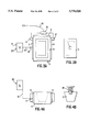
- FIG. 1 is a top view of a diagram of a mold apparatus and supporting hardware used in the present invention
- FIG. 2 is a front view diagram of the apparatus and supporting hardware shown in FIG. 1;
- FIG. 3A is a top view of a diagram of a female mold portion of a mold apparatus used in the present invention.
- FIG. 3B is a top view of a diagram of a male mold portion of a mold apparatus used in the present invention.
- FIG. 4A is a front view diagram of the female mold portion shown in FIG. 3A.
- FIG. 4B is a front view diagram of the male mold portion shown in FIG. 3B.
- the present invention is directed to modifications in the molding hardware and process to improve dimensional stability and minimize fabric curl distortion in compression molded fabrics.
- Fabric constructions suitable for use in the molding process according to the present invention include non-woven fabrics (preferably needlepunched), tufted fabrics, knitted fabrics and woven fabrics.
- the face fabrics may be made from polyolefins such as polypropylenes, polyesters, nylons, and/or thermoplastics having a lower melting point than polypropylene and propylene copolymers. Polypropylenes, and mixtures thereof with thermoplastics having a lower melting point than polypropylene are preferred.
- thermoplastics having a lower melting point than polypropylene are the REGALREZ family of resins that include hydrogenated styrenic based polymers with softening points ranging from about 85° C. to 140° C.
- the resins having softening points ranging between about 120° C. to 130° C. are preferred.
- a stable shape is imparted to textile fabrics (nonwoven, tufted, knitted and woven) by coating them with a moldable backing.
- the moldable backing is substantially rigid in its solid state, which it is in throughout the range of temperatures for its practical use. Moreover, the moldable backing has a lower melting point than the face fabric (nonwoven, tufted, knitted and woven) to which it is coated.
- Backcoatings suitable for molded shape retention include moldable latexes (e.g., ethylene vinyl acetate, styrene butyl rubber, acrylic), polyethylenes (e.g., extruded films), polypropylene copolymers and thermoplastics of a lower melting point than polypropylene, and moldable polyurethanes.
- the preferred backcoating materials are polyethylenes or polyethylenes and a latex binder layer for binding the face fabric with the backing layer.
- the backing layer i.e., moldable backing
- radiant heating such as infrared heating, electrical heating, or other known types of radiant heat in a preheating process prior to placing the fabric in a mold, until the backing layer has softened or melted.
- the preheating is preferably carried out through exposure to infrared heaters contained in an oven, which may be manually controlled or automated (e.g., through use of automatic timed cycles and/or automated temperature control).
- infrared heaters are heated to a temperature in the range of about 300° C. to about 500° C., preferably about 330° C. to about 450° C., and most preferably from about 360° C. to about 400° C. to heat the backing layer to a preferred temperature of about 150° C. to about 160° C., as measured by thermocouples on the backing layer.
- the fabric is preheated to a temperature which is above the melting point of the backing material but below the melting point of the face fabric.
- the fabric is heated to a temperature greater than or equal to about 125° C. (i.e., the melting point of the polyethylene backing) but less than about 165° C. (i.e., the melting point of the polypropylene face fabric).
- the face fabric generally stays about 20° C. to 40° C. cooler than the backing during the preheating stage.
- the preheat step can take from about 30 to about 120 seconds.
- the shortest acceptable time cycle to soften/melt the backing is used for production purposes, to maximize efficiency.
- the fabric After preheating, the fabric is held in a clip or pin frame 7 for automated processes (see FIGS. 1 and 2), or is placed by hand on a pin frame of the specified size in preparation for molding. The frame is then precisely positioned over a female portion 4 of a compression mold.
- the pin frame 7 is shown in phantom lines, in position for supporting a fabric above female mold portion 4 and beneath male mold portion 3.
- a supporting frame 2 is preferably made of stainless steel or other equivalent rigid material for supporting the pin frame 7 via brackets 15 and for supporting air cylinder mounting plate 13.
- Brackets 18 guide the pin frame and help maintain the pin frame in its proper position to ensure that it does not become misaligned during the process.
- Air cylinder 1 is securely fastened to (preferably by threaded engagement means, or other equivalent fixing means) and supported by air cylinder mounting plate 13.
- Air cylinder 1 is preferably a Bimba Model 7015--DXP Air Cylinder. However other equivalent and available air cylinders may be interchangeably used.
- a flow controller 11, also preferably supplied by Bimba is interconnected to the air cylinder 1, via tubing for regulating the supply of compressed air to the cylinder to actuate the same.
- Tubing 12 is preferably 1/4" plastic tubing, but other known equivalents may be interchangeably used.
- a disc valve 10, also preferably supplied by Bimba, is actuated to allow or prevent the flow of the compressed air to the flow controller 11, and is opened and closed to effect the same.
- the male portion of the mold 3 is securely fastened to (preferably by threaded engagement means 14, but other equivalent secure fixation means may be interchangeably used) and supported by the air cylinder 1 for actuation thereby.
- the invention may also be arranged so that the female portion of the mold is actuated by the air cylinder.
- strip plate heaters 5 are fixed (by screws, adhesives or other known fixing means) to the exterior sides of the female mold portion for actively heating the female portion of the mold during (and optionally, after) the molding process.
- Watlow from Batavia, Ill.
- other numbers of strip heaters may be used and equivalent strip heaters or other heating means may be interchangeably used in place of the Watlow strip heaters.
- the female mold may be provided with channels through which a heated liquid or gas medium may be passed to actively heat the female portion of the mold.
- the strip heaters 5 are provided with at least one temperature probe which is electrically connected to temperature control panel 6, which maintains the temperature of the strip heaters within a preselected temperature range.
- Temperature control panel 6 is also preferably supplied by Watlow. Temperature control panel 6 includes an ON/OFF button 19 for powering up and powering down the temperature control panel and temperature control apparatus.
- the temperature control panel 6 further includes a display panel 20 (preferably an LED display, however an LCD display or other known equivalent display means could be used interchangeably) for displaying the "setting temperature” (i.e., the desired or target temperature) and for displaying the actual temperature.
- a power supply cord 16 interconnects the strip heaters 5, via electrical joint box 21 and electrical connection boxes 5', and applies power to generate heat within the same, upon control thereof by the temperature control panel 6.
- Insulation plates 9 are provided over the front and back sides outside of the female mold portion to assist the strip heaters in maintenance of the desired temperature range of the female mold portion during (and optionally after) molding.
- the female mold portion is supported on the base 2' of the supporting frame 2, and is fit between supporting brackets 17 to ensure proper alignment of the female mold portion with the male mold portion during the molding process.
- FIG. 3A shows a top view of the female mold portion 4 and attached temperature control apparatus.
- the power supply cord 16 connects with the strip heaters 5 at 5'.
- the power supply is preferably 110 V AC, but 220 V AC or a DC supply source may also be used.
- FIG. 3B shows a top view of the male portion of the mold with the air cylinder attached. The phantom line indicates the boundary of the lower surface of the male portion of the mold.
- FIG. 4A shows a front view of the female mold portion 4 and attached temperature control apparatus shown in FIG. 3A. The inner surfaces of the female mold are shown in phantom lines.
- FIG. 4B shows a front view of the male mold portion 3 and the attachment 14 for connecting the male mold portion 3 to the air cylinder 1.
- male portion 3 of the compression mold having interfitting dimensions with the female portion 4, is mated with the female portion 4, thereby compressing the fabric between the male and female portions.
- the male and female portions of the compression mold may be fabricated from aluminum or other metals having good thermal conductivity.
- the mold portions may be constructed from fiberglass composites or other plastic composites capable of withstanding the temperatures and pressures exhibited during compression molding without distortion.
- An advantage of using composites is that they are readily adapted to fabrication into complex shapes with close tolerances.
- the mold portions may be modified to include heaters 5 in the mold portion (preferably the female mold portion 4) which is designed to interface with the face fabric, and optionally, to include coolers (not shown) in the mold portion (preferably the male mold portion 3) which is designed to interface with the backing.
- the heaters preferably comprise electrical resistors, such as thin coat strip heaters (e.g, rated at 240 V and 1250 watts) embedded in the walls or (preferably) coated, adhered or affixed on the wall surfaces of the mold portion to be heated.
- At least one thermocouple (e.g., temperature probe 8) is provided to monitor the temperature of the heaters, which are controlled by a thermostatic temperature controller and power switching device (e.g., temperature control panel 6).
- the heaters may comprise pipes built into the wall of the mold portion to circulate hot water and/or steam or other hot liquids and/or gases.
- the heaters are activated to supply heat to the face fabric. Since the molding portion has good thermal conductivity, heat is conducted from the heaters through the walls of the mold portion or directly transferred to the face fabric so as to heat the face fabric to the desired temperature range.
- the heaters increase and maintain the face fabric within a preferred range of about 60° C. to about 130° C., more preferably in the range of 80° C. to about 120° C., while the backing layer cools to a solidification temperature.
- the face fabric comprises polypropylene
- the most preferred temperature range is maintained at about 90° C. to 100° C.
- the backing comprises polyethylene
- the backing is preferably cooled to about 35° C. to 50° C.
- Typical molding time cycles preferably range from about 20 to about 180 seconds, more preferably from about 60 seconds to about 120 seconds, and most preferably from about 60 seconds to about 90 seconds.
- the coolers in the mold portion which is designed to interface with the backing layer may comprise pipes built into the wall of the mold portion to circulate chilled water or some other chilled liquid. Since the molding portion has good thermal conductivity, heat is conducted from the backing layer to the piped chilled substance through the walls of the mold portion, thereby cooling the backing layer to shorten the time it takes to solidify the backing layer.
- the maintenance of the face fabric within the temperature ranges described, allows stress relaxation of the face fabric material during the cooling process of the backing layer. Ordinarily, when the face fabric is allowed to cool along with the backing, stress concentrations build up in the face fabric and cause the unacceptable curling effect, as well as other dimensional distortions.
- the backing When the backing has been cooled to about 35° C. to 50° C., it achieves sufficient solidity and rigidity to hold the desired shape imparted to it by the mold.
- the molded fabric is then removed from the mold and placed on a trim tray having the same shape and dimensions as the mold. The molded fabric is then trimmed to the desired specifications, using water knives, or by manually cutting, for example. The fabric is removed from the trim tray, measured against specifications and stored for shipment.
- heaters of the type described above may also be provided in the walls of the trim tray which interface with the face fabric when the molded fabric is placed on the trim tray.
- the face fabric is further heated during the trim process, as a post molding step, to further facilitate stress relaxation in the face fabric.
- the face fabric is heated to a temperature in the preferred range of about 60° C. to about 130° C., more preferably in the range of about 80° C. to about 120° C., most preferably within the range of about 90° C. to about 100° C.
- the backing maintains a temperature below about 60° C. during the heating of the face fabric.
- the face fabric may be heated by placing the molded fabric and trim tray in a circulating hot air oven.
- the fabric is treated in the post-molding step for a time period preferably ranging from about 20 seconds to about 180 seconds, more preferably for about 60 seconds to about 120 seconds, most preferably for about 60 seconds to about 90 seconds.
- the modified trim tray and heating process can be used in conjunction with the heating/cooling compression molding, or instead of the heating/cooling compression molding process, in which case the known cold compression molding process would be substituted for the heating/cooling compression molding process.
- Table 1 shows the improved results which were obtained through the use of compression mold heating according to the present invention, post-mold heating (i.e., at the trim mold stage) without heating of the compression mold, and compression mold heating combined with post-mold heating. A control sample is also given in which the compression mold temperature was at room temperature and no post-mold heating was applied.
- the column heading "Denier” refers to the denier of the polypropylene fibers used in the face fabric of the particular sample.
- IR Heat and Seconds refers to the temperature of the IR source, and the length of time in seconds, which the IR heat at that temperature, was applied to the backing to achieve a preheating temperature of the backing within the range of 150° C. to 160° C., as measured by thermocouples.
- the samples used had dimensions of about 30" by 22".
- “Mold Temp” “RT” refers to room temperature, wherein the mold halves were not positively heated or cooled, but merely existed at room temperature prior to inserting the fabric for compression molding. The samples that were heated, were heated on the mold half which contacted the face fabric.
- the column heading “Time Sec.” includes the time that the sample is in the mold (i.e., the compression mold)+the time that the molded fabric is post mold heated in an oven (* --in Sample Nos. 14 and 15, the molded samples were not post mold heated in an oven, but were allowed to remain in the female portion of the mold, after the male portion of the mold was removed, for 30 seconds).
- sample Control 1 was preheated for 69 seconds and compression molded for 60 seconds.
- sample 14 was preheated for 60 seconds, compression molded for 60 seconds, and then the mold was opened, while the sample remained in the female half of the mold (with the face fabric contacting the female half) for 30 seconds.
- “Curl Distortion Angle” is a visual estimate of fabric deformation that occurs when a cut is made on the molded fabric and the cut edge is allowed to deform over time.
- the fabrics were removed from the pin frames after molding (and post-molding treatment, if any).
- Pressure sensors, thermocouples and/or any other instrumentation on the samples were removed, and the samples were then measured and cut.
- the samples were allowed to deform for 24 hours after cutting, before the visual estimates were performed.
- the angle numbers given for curl distortion indicate the deviation of the cut edges from their original position at the time of cutting.
- “Curl Rank” 1 is best for purposes of this invention, and 5 is worst.
- the dimensions of the fabric were about 30 inches long and 22 inches wide.
- the fabric was pinned in the length direction only.
- the pinned fabric was precisely positioned over a female portion of a compression mold.
- a male portion of the compression mold having interfitting dimensions with the female portion, was mated with the female portion, thereby compressing the fabric between the male and female portions.
- Both the female and male portions of the mold were at room temperature prior to mating the portions.
- the fabric was molded for approximately 60 seconds, after which the mold portions were separated and the molded fabric was removed from the mold.
- the fabric was then cut and the open fabric was allowed to deform for approximately 24 hours.
- the curl distortion angle of the open fabric was observed to be greater than 90 degrees, as measured from the surface of the fabric to the curl edge.
- Comparative Examples 2-11 were carried out using the same techniques described in Comparative Example 1 above, but modified using the conditions, parameters and materials as set forth in Table 1 above.
- the fabric was pinned in the length direction only.
- the pinned fabric was precisely positioned over a female portion of a compression mold.
- a male portion of the compression mold had interfitting dimensions with the female portion.
- the female portion was modified by adding thin coat strip heaters (240 V, 1250 watts), thermocouples, a temperature controller and a power switching device.
- the female mold portion was heated to 100° C. as measured by the thermocouples and the male portion was mated therewith (the male portion was at room temperature), thereby compressing the fabric between the male and female portions.
- the fabric was molded for approximately 70 seconds, after which the mold portions were separated and the molded fabric was removed from the mold.
- the fabric was then cut and the open fabric was allowed to deform for approximately 24 hours.
- the curl distortion angle of the open fabric was observed to be less than 20 degrees, as measured from the surface of the fabric to the curl edge.
- the dimensions of the fabric were about 30 inches long and 22 inches wide.
- the fabric was pinned in the length direction only.
- the pinned fabric was precisely positioned over a female portion of a compression mold.
- a male portion of the compression mold had interfitting dimensions with the female portion.
- the female portion was not modified with thin coat strip heaters.
- the female mold portion was at room temperature and the male portion (also at room temperature) was mated therewith, thereby compressing the fabric between the male and female portions.
- the fabric was molded for approximately 60 seconds, after which the mold portions were separated and the molded fabric was removed from the mold.
- the fabric was immediately placed in a hot air oven having an environment temperature of 90° C. for 180 seconds for post-mold heating.
- the fabric was then cut and the open fabric was allowed to deform for approximately 24 hours.
- the curl distortion angle of the open fabric was observed to be less than 20 degrees, as measured from the surface of the fabric to the curl edge.
- the dimensions of the fabric were about 30 inches long and 22 inches wide.
- the fabric was pinned in the length direction only.
- the pinned fabric was precisely positioned over a female portion of a compression mold.
- a male portion of the compression mold had interfitting dimensions with the female portion.
- the female portion was modified by adding thin coat strip heaters (240 V, 1250 watts), thermocouples, a temperature controller and a power switching device.
- the female mold portion was heated to 100° C. as measured by the thermocouples and the male portion was mated therewith (the male portion was at room temperature), thereby compressing the fabric between the male and female portions.
- the fabric was molded for approximately 60 seconds, after which the male mold portion was separated from the female mold portion.
- the molded fabric was then allowed to remain in the female portion of the mold for 30 seconds while the remaining heat in the female portion of the mold effected post-mold heating.
- the fabric was then cut and the open fabric was allowed to deform for approximately 24 hours.
- the curl distortion angle of the open fabric was observed to be less than 20 degrees, as measured from the surface of the fabric to the curl edge.
- a second arm or axis is arranged preferably at a diagonal direction which is about 45° with respect to the machine direction (i.e., axis in the machine direction), and a third axis or arm is placed at a cross direction which is preferably at about 90° with respect to the machine direction, and about 45° with respect to the diagonal direction.
- the arranged fabric is then placed in an oven at room temperature; heated to a temperature of about 100° F. to about 200° F., preferably from about 120° F. to about 140° F., and even more preferably from about 127° F. to about 135° F.; and cooled back to room temperature.
- the heating and cooling stages are performed at a rate of about 20° F. per minute.
- the fabric is then preferably maintained within that heating range for preferably about two hours, but this time can be adjusted as required.
- the preferred test temperatures are determined according to actual temperatures that the fabric may be exposed to.
- the fabric may be subject to temperatures of 130° F. to 140° F. during storage, prior to installation, and thus must be able to stably withstand these temperatures without dimensional distortion.
- the probes which are placed on the fabric during testing record any dimensional changes in the fabric as the temperature increases to the target range, during the exposure period at the target range, and during cooling back to the room temperature. Test results are recorded as percent change from the original dimension. A negative value indicates shrinkage, whereas a positive value indicates expansion.
Abstract
Description
                                  TABLE 1
__________________________________________________________________________
                                 Post     Curl
Sample   Polypropylene
                 Backing
                       IR Heat
                             Mold
                                 Mold
                                     Time Distor-
                                              Curl.sup.(3)
No.  Denier
         Fabric Type
                 Materials
                       & Seconds
                             Temp
                                 Mold
                                     Sec. tion
                                              Rank
__________________________________________________________________________
Control 1
     17  15 oz   Latex + PE
                       360°/69
                             RT  None
                                     60 + 0
                                          >90°
                                              5
         Random Velour
Control 2
     17  15 oz   Latex +  PE
                       360°/60
                             RT  None
                                     60 + 0
                                          >60°
                                              4
         Random Velour
Control 3
     17  14 oz   PE    360°/67
                             RT  None
                                     60 + 0
                                          >60°
                                              5
         Needled Loop
Control 4
     17  14 oz   PE    360°/60
                             RT  None
                                     95 + 0
                                          >45°
                                              4
         Needled Loop
Control 5
     17  14 oz   PE    360°/67
                             RT  None
                                     90 + 0
                                          >45°
                                              4
         Needled Loop
Control 6
     17  15 oz   PE    360°/94
                             RT  None
                                     90 + 0
                                          >30°
                                              3
         Needled Loop
Control 7
     17  15 oz   PE    360°/60
                             RT  None
                                     60 + 0
                                          >30°
                                              3
         Needled Loop
Control 8
     17  15 oz   PE    360°/79
                             RT  None
                                     60 + 0
                                          >45°
                                              4
         Needled Loop
Control 9
     17  15 oz   PE    360°/82
                             RT  None
                                     60 + 0
                                          >45°
                                              4
         Needled Loop
Control 10
     17  15 oz   Latex + PE
                       360°/77
                             RT  None
                                     60 + 0
                                          >60°
                                              4
         Random Velour
Control 11
     17  15 oz   Latex + PE
                       400° C./60
                             RT  None
                                     60 + 0
                                          >90 5
         Random Velour
     17  15 oz   Latex + PE
                       400° C./105
                             RT  95° C.
                                     60 + 180
                                          <20 2
         Random Velour
     17  15 oz   Latex + PE
                       400° C./117
                             RT  95° C.
                                     60 + 180
                                          <20 2
         Random Velour
     17  15 oz   Latex + PE
                       400° C./120
                             RT  90°C.
                                     60 + 75
                                          <40 3
         Random Velour
     17  15 oz   Latex + PE
                       400° C./83
                             RT  90°C.
                                     60 + 180
                                          <20 2
         Random Velour
     17  14 oz   PE    400° C./90
                             RT  90°C.
                                     60 + 180
                                          Zero
                                              1
         Needled Loop
     17  14 oz   PE    400° C./86
                             RT  90°C.
                                     60 + 180
                                          <20 2
         Needled Loop
     17  14 oz   PE    400° C./94
                             RT  90°C.
                                     60 + 180
                                          <40 3
         Needled Loop
     17  14 oz   PE    400° C./97
                             RT  90°C.
                                     60 + 180
                                          <20 2
         Needled Loop
     17  14 oz   PE    400° C./84
                             RT  90° C.
                                     60 + 180
                                          Zero
                                              1
         Needled Loop
     17  15 oz   Latex + PE
                       400° C./60
                             75° C.
                                 None
                                     60 + 0
                                          <40 3
         Random Velour
     17  15 oz   Latex + PE
                       400° C./60
                             90° C.
                                 None
                                     60 + 0
                                          <40 3
         Random Velour
     17  15 oz   Latex + PE
                       400° C./45
                             90° C.
                                 None
                                     60 + 0
                                          <20 2
         Random Velour
     17  15 oz   Latex + PE
                       400° C./60
                             100° C.
                                 None
                                     70 + 0
                                          <20 2
         Random Velour
     17  14 oz   PE    400° C./60
                             90° C.
                                 None
                                     60 + 30*
                                          <20 2
         Needled Loop
     17  14 oz   PE    400° C./60
                             90° C.
                                 None
                                     60 + 30*
                                          <20 2
         Needled Loop
__________________________________________________________________________
                                  TABLE 2
__________________________________________________________________________
                       Dimensional Stability Test
                       Maximum Change
                       % Shrinkage (-); Growth (+)
                       Tester   Cross
                                    Diagonal
Sample
     Fabric
          Backing
                Mold
                    Time
                       Heat
                           Machine
                                Direc-
                                    Direc-
Number
     Type Materials
                Temp
                    Sec.
                       °F.
                           Direction
                                tion
                                    tion Rank
__________________________________________________________________________
Control 1
     Polyester
          Latex + PE
                RT  60 131 -0.1 -0.5
                                    -0.2 1
     Random
     Velour
Control 2
     Poly-
          Latex + PE
                RT  60 135 -0.7 -0.8
                                    -0.6 5
     propylene
     Random
     Velour
     Poly-
          Latex + PE
                75° C.
                    60 127 -0.6 -0.6
                                    -0.6 3
     propylene
     Random
     Velour
     Poly-
          Latex + PE
                90° C.
                    60 133 -0.35
                                -0.6
                                    -0.6 2
     Propylene
     Random
     Velour
__________________________________________________________________________
Claims (28)
Priority Applications (1)
| Application Number | Priority Date | Filing Date | Title |
|---|---|---|---|
| US08/583,513 US5756026A (en) | 1996-01-05 | 1996-01-05 | Method for control of post molding fabric curl and distortion |
Applications Claiming Priority (1)
| Application Number | Priority Date | Filing Date | Title |
|---|---|---|---|
| US08/583,513 US5756026A (en) | 1996-01-05 | 1996-01-05 | Method for control of post molding fabric curl and distortion |
Publications (1)
| Publication Number | Publication Date |
|---|---|
| US5756026A true US5756026A (en) | 1998-05-26 |
Family
ID=24333405
Family Applications (1)
| Application Number | Title | Priority Date | Filing Date |
|---|---|---|---|
| US08/583,513 Expired - Fee Related US5756026A (en) | 1996-01-05 | 1996-01-05 | Method for control of post molding fabric curl and distortion |
Country Status (1)
| Country | Link |
|---|---|
| US (1) | US5756026A (en) |
Cited By (23)
| Publication number | Priority date | Publication date | Assignee | Title |
|---|---|---|---|---|
| US6476783B2 (en) * | 1998-02-17 | 2002-11-05 | Sarnoff Corporation | Contrast enhancement for an electronic display device by using a black matrix and lens array on outer surface of display |
| US20030008592A1 (en) * | 2000-06-30 | 2003-01-09 | Block Thomas L. | Hood, dash, firewall or engine cover liner |
| US6572723B1 (en) | 2000-06-30 | 2003-06-03 | Owens Corning Fiberglas Technology, Inc. | Process for forming a multilayer, multidensity composite insulator |
| WO2003068474A1 (en) * | 2002-02-13 | 2003-08-21 | Darco Industries Llc | Plastic toe cap and method of making |
| US6669265B2 (en) | 2000-06-30 | 2003-12-30 | Owens Corning Fiberglas Technology, Inc. | Multidensity liner/insulator |
| US20040046274A1 (en) * | 2002-09-06 | 2004-03-11 | Chi-Kung Wu | Method for producing a wear-resisting outsole |
| US20050078104A1 (en) * | 1998-02-17 | 2005-04-14 | Matthies Dennis Lee | Tiled electronic display structure |
| US20050127575A1 (en) * | 2003-12-15 | 2005-06-16 | Dry Alan G. | Method of forming a vehicle trim panel |
| US6955845B1 (en) | 2000-06-30 | 2005-10-18 | Owens Corning Fiberglas Technology, Inc. | Acoustical and thermal insulator |
| US20060157640A1 (en) * | 2005-01-18 | 2006-07-20 | Perlman Stephen G | Apparatus and method for capturing still images and video using coded aperture techniques |
| US20090167922A1 (en) * | 2005-01-18 | 2009-07-02 | Perlman Stephen G | Apparatus and method for capturing still images and video using coded lens imaging techniques |
| US20110117314A1 (en) * | 2009-11-17 | 2011-05-19 | Toyota Motor Engineering & Manufacturing North America, Inc. | Console carpet |
| US9819403B2 (en) | 2004-04-02 | 2017-11-14 | Rearden, Llc | System and method for managing handoff of a client between different distributed-input-distributed-output (DIDO) networks based on detected velocity of the client |
| US9826537B2 (en) | 2004-04-02 | 2017-11-21 | Rearden, Llc | System and method for managing inter-cluster handoff of clients which traverse multiple DIDO clusters |
| US9923657B2 (en) | 2013-03-12 | 2018-03-20 | Rearden, Llc | Systems and methods for exploiting inter-cell multiplexing gain in wireless cellular systems via distributed input distributed output technology |
| US9973246B2 (en) | 2013-03-12 | 2018-05-15 | Rearden, Llc | Systems and methods for exploiting inter-cell multiplexing gain in wireless cellular systems via distributed input distributed output technology |
| US10148897B2 (en) | 2005-07-20 | 2018-12-04 | Rearden, Llc | Apparatus and method for capturing still images and video using coded lens imaging techniques |
| US10277290B2 (en) | 2004-04-02 | 2019-04-30 | Rearden, Llc | Systems and methods to exploit areas of coherence in wireless systems |
| US10333604B2 (en) | 2004-04-02 | 2019-06-25 | Rearden, Llc | System and method for distributed antenna wireless communications |
| US10425134B2 (en) | 2004-04-02 | 2019-09-24 | Rearden, Llc | System and methods for planned evolution and obsolescence of multiuser spectrum |
| US10488535B2 (en) | 2013-03-12 | 2019-11-26 | Rearden, Llc | Apparatus and method for capturing still images and video using diffraction coded imaging techniques |
| US10547358B2 (en) | 2013-03-15 | 2020-01-28 | Rearden, Llc | Systems and methods for radio frequency calibration exploiting channel reciprocity in distributed input distributed output wireless communications |
| US11189917B2 (en) | 2014-04-16 | 2021-11-30 | Rearden, Llc | Systems and methods for distributing radioheads |
Citations (17)
| Publication number | Priority date | Publication date | Assignee | Title |
|---|---|---|---|---|
| US2305433A (en) * | 1940-09-11 | 1942-12-15 | Jesse B Hawley | Method and apparatus for molding articles of thermoplastic, thermosetting, or resinous materials |
| US2891279A (en) * | 1952-06-10 | 1959-06-23 | C F Roser G M B H | Process of and apparatus for the manufacture of paper-like materials from thermoplastic synthetic materials |
| US3049762A (en) * | 1959-04-23 | 1962-08-21 | Imp Eastman Corp | Reinforced flexible tubing |
| US3150024A (en) * | 1960-09-20 | 1964-09-22 | Magee Carpet Co | Method and apparatus for laminating a layer of plastic and scrim on the backing of carpet |
| US3209467A (en) * | 1961-10-16 | 1965-10-05 | Monsanto Co | Strand annealers |
| US3555135A (en) * | 1968-02-29 | 1971-01-12 | Phillips Petroleum Co | Stress relieving of molded plastic structures |
| US3673034A (en) * | 1969-05-05 | 1972-06-27 | William H Squier | Method for coating,laminating,and molding automobile floor coverings |
| US4157415A (en) * | 1976-11-05 | 1979-06-05 | Hugo Lindenberg | Laminated panel construction and method of making same |
| US4174991A (en) * | 1978-11-13 | 1979-11-20 | The Akro Corporation | Process of laminating carpet to elastomeric backing |
| US4189336A (en) * | 1976-10-07 | 1980-02-19 | Imperial Chemical Industries Limited | Method of forming pile products by tack-spinning and heat treatment therefore |
| US4357381A (en) * | 1980-11-20 | 1982-11-02 | Wilson Ted R | Thermoplastic building enclosure member |
| US4581272A (en) * | 1985-01-11 | 1986-04-08 | Gates Formed-Fibre Products, Inc. | Automotive vehicle door kick panel and method of manufacture |
| US4590027A (en) * | 1976-06-10 | 1986-05-20 | Murphy David J | Method of producing a thermoplastics material |
| US4617208A (en) * | 1983-07-19 | 1986-10-14 | Modern Fibers, Inc. | Non-directional, synthetic, outdoor carpet |
| US4750374A (en) * | 1986-10-16 | 1988-06-14 | Hercules Incorporated | Process and apparatus for monitoring laminate structural stability |
| USH559H (en) * | 1987-05-12 | 1988-12-06 | The United States Of America As Represented By The Secretary Of The Air Force | Advancing gelation front cure technique |
| US5164142A (en) * | 1991-09-20 | 1992-11-17 | Westinghouse Electric Corp. | Stepmolding process and apparatus |
-
1996
- 1996-01-05 US US08/583,513 patent/US5756026A/en not_active Expired - Fee Related
Patent Citations (17)
| Publication number | Priority date | Publication date | Assignee | Title |
|---|---|---|---|---|
| US2305433A (en) * | 1940-09-11 | 1942-12-15 | Jesse B Hawley | Method and apparatus for molding articles of thermoplastic, thermosetting, or resinous materials |
| US2891279A (en) * | 1952-06-10 | 1959-06-23 | C F Roser G M B H | Process of and apparatus for the manufacture of paper-like materials from thermoplastic synthetic materials |
| US3049762A (en) * | 1959-04-23 | 1962-08-21 | Imp Eastman Corp | Reinforced flexible tubing |
| US3150024A (en) * | 1960-09-20 | 1964-09-22 | Magee Carpet Co | Method and apparatus for laminating a layer of plastic and scrim on the backing of carpet |
| US3209467A (en) * | 1961-10-16 | 1965-10-05 | Monsanto Co | Strand annealers |
| US3555135A (en) * | 1968-02-29 | 1971-01-12 | Phillips Petroleum Co | Stress relieving of molded plastic structures |
| US3673034A (en) * | 1969-05-05 | 1972-06-27 | William H Squier | Method for coating,laminating,and molding automobile floor coverings |
| US4590027A (en) * | 1976-06-10 | 1986-05-20 | Murphy David J | Method of producing a thermoplastics material |
| US4189336A (en) * | 1976-10-07 | 1980-02-19 | Imperial Chemical Industries Limited | Method of forming pile products by tack-spinning and heat treatment therefore |
| US4157415A (en) * | 1976-11-05 | 1979-06-05 | Hugo Lindenberg | Laminated panel construction and method of making same |
| US4174991A (en) * | 1978-11-13 | 1979-11-20 | The Akro Corporation | Process of laminating carpet to elastomeric backing |
| US4357381A (en) * | 1980-11-20 | 1982-11-02 | Wilson Ted R | Thermoplastic building enclosure member |
| US4617208A (en) * | 1983-07-19 | 1986-10-14 | Modern Fibers, Inc. | Non-directional, synthetic, outdoor carpet |
| US4581272A (en) * | 1985-01-11 | 1986-04-08 | Gates Formed-Fibre Products, Inc. | Automotive vehicle door kick panel and method of manufacture |
| US4750374A (en) * | 1986-10-16 | 1988-06-14 | Hercules Incorporated | Process and apparatus for monitoring laminate structural stability |
| USH559H (en) * | 1987-05-12 | 1988-12-06 | The United States Of America As Represented By The Secretary Of The Air Force | Advancing gelation front cure technique |
| US5164142A (en) * | 1991-09-20 | 1992-11-17 | Westinghouse Electric Corp. | Stepmolding process and apparatus |
Cited By (34)
| Publication number | Priority date | Publication date | Assignee | Title |
|---|---|---|---|---|
| US20050078104A1 (en) * | 1998-02-17 | 2005-04-14 | Matthies Dennis Lee | Tiled electronic display structure |
| US7864136B2 (en) | 1998-02-17 | 2011-01-04 | Dennis Lee Matthies | Tiled electronic display structure |
| US6476783B2 (en) * | 1998-02-17 | 2002-11-05 | Sarnoff Corporation | Contrast enhancement for an electronic display device by using a black matrix and lens array on outer surface of display |
| US7592970B2 (en) | 1998-02-17 | 2009-09-22 | Dennis Lee Matthies | Tiled electronic display structure |
| US20080174515A1 (en) * | 1998-02-17 | 2008-07-24 | Dennis Lee Matthies | Tiled electronic display structure |
| US6669265B2 (en) | 2000-06-30 | 2003-12-30 | Owens Corning Fiberglas Technology, Inc. | Multidensity liner/insulator |
| US6955845B1 (en) | 2000-06-30 | 2005-10-18 | Owens Corning Fiberglas Technology, Inc. | Acoustical and thermal insulator |
| US8361912B2 (en) | 2000-06-30 | 2013-01-29 | Owens Corning Intellectual Capital, Llc | Hood, dash, firewall or engine cover liner |
| US6572723B1 (en) | 2000-06-30 | 2003-06-03 | Owens Corning Fiberglas Technology, Inc. | Process for forming a multilayer, multidensity composite insulator |
| US20030008592A1 (en) * | 2000-06-30 | 2003-01-09 | Block Thomas L. | Hood, dash, firewall or engine cover liner |
| WO2003068474A1 (en) * | 2002-02-13 | 2003-08-21 | Darco Industries Llc | Plastic toe cap and method of making |
| US20040046274A1 (en) * | 2002-09-06 | 2004-03-11 | Chi-Kung Wu | Method for producing a wear-resisting outsole |
| US20050127575A1 (en) * | 2003-12-15 | 2005-06-16 | Dry Alan G. | Method of forming a vehicle trim panel |
| US10425134B2 (en) | 2004-04-02 | 2019-09-24 | Rearden, Llc | System and methods for planned evolution and obsolescence of multiuser spectrum |
| US10333604B2 (en) | 2004-04-02 | 2019-06-25 | Rearden, Llc | System and method for distributed antenna wireless communications |
| US10277290B2 (en) | 2004-04-02 | 2019-04-30 | Rearden, Llc | Systems and methods to exploit areas of coherence in wireless systems |
| US9826537B2 (en) | 2004-04-02 | 2017-11-21 | Rearden, Llc | System and method for managing inter-cluster handoff of clients which traverse multiple DIDO clusters |
| US9819403B2 (en) | 2004-04-02 | 2017-11-14 | Rearden, Llc | System and method for managing handoff of a client between different distributed-input-distributed-output (DIDO) networks based on detected velocity of the client |
| US20100220212A1 (en) * | 2005-01-18 | 2010-09-02 | Perlman Stephen G | Apparatus and method for capturing still images and video using coded lens imaging techniques |
| US20090167922A1 (en) * | 2005-01-18 | 2009-07-02 | Perlman Stephen G | Apparatus and method for capturing still images and video using coded lens imaging techniques |
| US8288704B2 (en) | 2005-01-18 | 2012-10-16 | Rearden, Llc | Apparatus and method for capturing still images and video using coded lens imaging techniques |
| US20060157640A1 (en) * | 2005-01-18 | 2006-07-20 | Perlman Stephen G | Apparatus and method for capturing still images and video using coded aperture techniques |
| US7767949B2 (en) * | 2005-01-18 | 2010-08-03 | Rearden, Llc | Apparatus and method for capturing still images and video using coded aperture techniques |
| US7767950B2 (en) * | 2005-01-18 | 2010-08-03 | Rearden, Llc | Apparatus and method for capturing still images and video using coded aperture techniques |
| US8013285B2 (en) | 2005-01-18 | 2011-09-06 | Rearden, Llc | Apparatus and method for capturing still images and video using coded lens imaging techniques |
| US7671321B2 (en) | 2005-01-18 | 2010-03-02 | Rearden, Llc | Apparatus and method for capturing still images and video using coded lens imaging techniques |
| US10148897B2 (en) | 2005-07-20 | 2018-12-04 | Rearden, Llc | Apparatus and method for capturing still images and video using coded lens imaging techniques |
| US20110117314A1 (en) * | 2009-11-17 | 2011-05-19 | Toyota Motor Engineering & Manufacturing North America, Inc. | Console carpet |
| US9973246B2 (en) | 2013-03-12 | 2018-05-15 | Rearden, Llc | Systems and methods for exploiting inter-cell multiplexing gain in wireless cellular systems via distributed input distributed output technology |
| US9923657B2 (en) | 2013-03-12 | 2018-03-20 | Rearden, Llc | Systems and methods for exploiting inter-cell multiplexing gain in wireless cellular systems via distributed input distributed output technology |
| US10488535B2 (en) | 2013-03-12 | 2019-11-26 | Rearden, Llc | Apparatus and method for capturing still images and video using diffraction coded imaging techniques |
| US10547358B2 (en) | 2013-03-15 | 2020-01-28 | Rearden, Llc | Systems and methods for radio frequency calibration exploiting channel reciprocity in distributed input distributed output wireless communications |
| US11146313B2 (en) | 2013-03-15 | 2021-10-12 | Rearden, Llc | Systems and methods for radio frequency calibration exploiting channel reciprocity in distributed input distributed output wireless communications |
| US11189917B2 (en) | 2014-04-16 | 2021-11-30 | Rearden, Llc | Systems and methods for distributing radioheads |
Similar Documents
| Publication | Publication Date | Title |
|---|---|---|
| US5756026A (en) | Method for control of post molding fabric curl and distortion | |
| US5132166A (en) | Semirigid luggage shell and method for its production | |
| CA2136170C (en) | Process for manufacturing a padded element | |
| Ashter | Thermoforming of Single and Multilayer Laminates: Plastic Films Technologies, Testing, and Applications | |
| CA1334613C (en) | Process for producing a multilayer molded article | |
| US5084317A (en) | Pressure-sensitive adhesive release liner | |
| US4721643A (en) | Laminated structure for interior finishing materials, and method of production thereof | |
| AU589016B2 (en) | Apparatus and process for shaping and covering cushion foam | |
| JPS63502419A (en) | Equipment for laminating and shaping forms | |
| US4595551A (en) | Thermoforming of styrenic foam laminates | |
| SK47296A3 (en) | Method for manufacturing decorative panels and device for carrying out this method | |
| CA1317078C (en) | Method for producing decorative seams on films shaped by drawing method, and apparatus for performing the method | |
| US5585061A (en) | Method for producing a multilayer molded article | |
| WO1988001565A1 (en) | Process of forming a contoured insulating sheet | |
| Dutta et al. | Thermoforming of advanced thermoplastic composites. I: Single curvature parts | |
| JP5688921B2 (en) | POLYESTER THERMOFORMED ARTICLE AND METHOD FOR PRODUCING THE SAME | |
| US20100040824A1 (en) | Threaded Connector Formed On A Surface | |
| JP2002326319A (en) | Thermosetting resin decorative material | |
| Cakmak et al. | Instrumented thermoforming of advanced thermoplastic composites. II: Dynamics of double curvature part formation and structure development from PEEK/carbon fiber prepreg tapes | |
| JPH1016042A (en) | Blow-molded article and molding method | |
| JPH0764030B2 (en) | Attachment device for nonwoven thermoformed articles and method of making same | |
| US6235138B1 (en) | Polyurethane foam/PVC laminate for automotive instrument panels | |
| CA2086246C (en) | Multilayer molded article and method for producing the same | |
| EP0397331A2 (en) | Laminated fabric suitable for use in automotive interior applications | |
| US4581193A (en) | Method for molding a pile fabric |
Legal Events
| Date | Code | Title | Description |
|---|---|---|---|
| AS | Assignment |
Owner name: HERCULES INCORPORATED, DELAWARE Free format text: ASSIGNMENT OF ASSIGNORS INTEREST;ASSIGNORS:FREEMAN, WALTER J.;SANCHEZ, WILLIAM L.;REEL/FRAME:008149/0719;SIGNING DATES FROM 19960829 TO 19960906 |
|
| AS | Assignment |
Owner name: FIBERCO, INC., DELAWARE Free format text: ASSIGNMENT OF ASSIGNORS INTEREST;ASSIGNOR:HERCULES INCORPORTED;REEL/FRAME:008639/0239 Effective date: 19970624 |
|
| AS | Assignment |
Owner name: NATIONSBANK, N.A., AS AGENT, NORTH CAROLINA Free format text: NOTICE OF GRANT OF SECURITY INTEREST IN PATENTS;ASSIGNOR:FIBERCO, INC.;REEL/FRAME:008766/0071 Effective date: 19970924 |
|
| AS | Assignment |
Owner name: FIBERCO, INC., DELAWARE Free format text: ASSIGNMENT OF ASSIGNORS INTEREST;ASSIGNOR:NATIONSBANK, N.A., AS AGENT;REEL/FRAME:009719/0083 Effective date: 19990107 |
|
| AS | Assignment |
Owner name: BANK OF AMERICA, N.A., AS COLLATERAL AGENT, NORTH Free format text: SECURITY INTEREST;ASSIGNORS:HERCULES INCORPORATED, A DELAWARE CORPORATION;HERCULES CREDIT, INC., A DELAWARE CORPORATION;HERCULES FLAVOR, INC., A DELAWARE CORPORATION;AND OTHERS;REEL/FRAME:011436/0774 Effective date: 20001114 |
|
| FPAY | Fee payment |
Year of fee payment: 4 |
|
| FEPP | Fee payment procedure |
Free format text: PAYOR NUMBER ASSIGNED (ORIGINAL EVENT CODE: ASPN); ENTITY STATUS OF PATENT OWNER: LARGE ENTITY |
|
| AS | Assignment |
Owner name: CREDIT SUISSE FIRST BOSTON, AS COLLATERAL AGENT, N Free format text: SECURITY INTEREST;ASSIGNOR:HERCULES INCORPORATED;REEL/FRAME:013625/0233 Effective date: 20021220 |
|
| AS | Assignment |
Owner name: AQUALON COMPANY, DELAWARE Free format text: RELEASE OF SECURITY INTEREST;ASSIGNOR:BANK OF AMERICA, N.A., AS COLLATERAL AGENT;REEL/FRAME:013625/0224 Effective date: 20021219 Owner name: ATHENS HOLDINGS, INC., DELAWARE Free format text: RELEASE OF SECURITY INTEREST;ASSIGNOR:BANK OF AMERICA, N.A., AS COLLATERAL AGENT;REEL/FRAME:013625/0224 Effective date: 20021219 Owner name: BETZDEARBORN CHINA, LTD., DELAWARE Free format text: RELEASE OF SECURITY INTEREST;ASSIGNOR:BANK OF AMERICA, N.A., AS COLLATERAL AGENT;REEL/FRAME:013625/0224 Effective date: 20021219 Owner name: BETZDEARBORN EUROPE, INC., DELAWARE Free format text: RELEASE OF SECURITY INTEREST;ASSIGNOR:BANK OF AMERICA, N.A., AS COLLATERAL AGENT;REEL/FRAME:013625/0224 Effective date: 20021219 Owner name: BETZDEARBORN INTERNATIONAL, INC., DELAWARE Free format text: RELEASE OF SECURITY INTEREST;ASSIGNOR:BANK OF AMERICA, N.A., AS COLLATERAL AGENT;REEL/FRAME:013625/0224 Effective date: 20021219 Owner name: BETZDEARBORN, INC., DELAWARE Free format text: RELEASE OF SECURITY INTEREST;ASSIGNOR:BANK OF AMERICA, N.A., AS COLLATERAL AGENT;REEL/FRAME:013625/0224 Effective date: 20021219 Owner name: BL CHEMICALS INC., DELAWARE Free format text: RELEASE OF SECURITY INTEREST;ASSIGNOR:BANK OF AMERICA, N.A., AS COLLATERAL AGENT;REEL/FRAME:013625/0224 Effective date: 20021219 Owner name: BL TECHNOLOGIES, INC., DELAWARE Free format text: RELEASE OF SECURITY INTEREST;ASSIGNOR:BANK OF AMERICA, N.A., AS COLLATERAL AGENT;REEL/FRAME:013625/0224 Effective date: 20021219 Owner name: BLI HOLDING CORPORATION, DELAWARE Free format text: RELEASE OF SECURITY INTEREST;ASSIGNOR:BANK OF AMERICA, N.A., AS COLLATERAL AGENT;REEL/FRAME:013625/0224 Effective date: 20021219 Owner name: CHEMICAL TECHNOLOGIES INDIA, LTD., DELAWARE Free format text: RELEASE OF SECURITY INTEREST;ASSIGNOR:BANK OF AMERICA, N.A., AS COLLATERAL AGENT;REEL/FRAME:013625/0224 Effective date: 20021219 Owner name: COVINGTON HOLDINGS, INC., DELAWARE Free format text: RELEASE OF SECURITY INTEREST;ASSIGNOR:BANK OF AMERICA, N.A., AS COLLATERAL AGENT;REEL/FRAME:013625/0224 Effective date: 20021219 Owner name: D R C LTD., DELAWARE Free format text: RELEASE OF SECURITY INTEREST;ASSIGNOR:BANK OF AMERICA, N.A., AS COLLATERAL AGENT;REEL/FRAME:013625/0224 Effective date: 20021219 Owner name: EAST BAY REALTY SERVICES, INC., DELAWARE Free format text: RELEASE OF SECURITY INTEREST;ASSIGNOR:BANK OF AMERICA, N.A., AS COLLATERAL AGENT;REEL/FRAME:013625/0224 Effective date: 20021219 Owner name: FIBERVISIONS INCORPORATED, DELAWARE Free format text: RELEASE OF SECURITY INTEREST;ASSIGNOR:BANK OF AMERICA, N.A., AS COLLATERAL AGENT;REEL/FRAME:013625/0224 Effective date: 20021219 Owner name: FIBERVISIONS PRODUCTS, INC., DELAWARE Free format text: RELEASE OF SECURITY INTEREST;ASSIGNOR:BANK OF AMERICA, N.A., AS COLLATERAL AGENT;REEL/FRAME:013625/0224 Effective date: 20021219 Owner name: FIBERVISIONS, L.L.C., DELAWARE Free format text: RELEASE OF SECURITY INTEREST;ASSIGNOR:BANK OF AMERICA, N.A., AS COLLATERAL AGENT;REEL/FRAME:013625/0224 Effective date: 20021219 Owner name: FIBERVISIONS, L.P., DELAWARE Free format text: RELEASE OF SECURITY INTEREST;ASSIGNOR:BANK OF AMERICA, N.A., AS COLLATERAL AGENT;REEL/FRAME:013625/0224 Effective date: 20021219 Owner name: HERCULES CHEMICAL CORPORATION, DELAWARE Free format text: RELEASE OF SECURITY INTEREST;ASSIGNOR:BANK OF AMERICA, N.A., AS COLLATERAL AGENT;REEL/FRAME:013625/0224 Effective date: 20021219 Owner name: HERCULES COUNTRY CLUB, INC., DELAWARE Free format text: RELEASE OF SECURITY INTEREST;ASSIGNOR:BANK OF AMERICA, N.A., AS COLLATERAL AGENT;REEL/FRAME:013625/0224 Effective date: 20021219 Owner name: HERCULES CREDIT, INC., DELAWARE Free format text: RELEASE OF SECURITY INTEREST;ASSIGNOR:BANK OF AMERICA, N.A., AS COLLATERAL AGENT;REEL/FRAME:013625/0224 Effective date: 20021219 Owner name: HERCULES EURO HOLDINGS, LLC, DELAWARE Free format text: RELEASE OF SECURITY INTEREST;ASSIGNOR:BANK OF AMERICA, N.A., AS COLLATERAL AGENT;REEL/FRAME:013625/0224 Effective date: 20021219 Owner name: HERCULES FINANCE COMPANY, DELAWARE Free format text: RELEASE OF SECURITY INTEREST;ASSIGNOR:BANK OF AMERICA, N.A., AS COLLATERAL AGENT;REEL/FRAME:013625/0224 Effective date: 20021219 Owner name: HERCULES FLAVOR, INC., DELAWARE Free format text: RELEASE OF SECURITY INTEREST;ASSIGNOR:BANK OF AMERICA, N.A., AS COLLATERAL AGENT;REEL/FRAME:013625/0224 Effective date: 20021219 Owner name: HERCULES INCORPORATED, DELAWARE Free format text: RELEASE OF SECURITY INTEREST;ASSIGNOR:BANK OF AMERICA, N.A., AS COLLATERAL AGENT;REEL/FRAME:013625/0224 Effective date: 20021219 Owner name: HERCULES INTERNATIONAL LIMITED, DELAWARE Free format text: RELEASE OF SECURITY INTEREST;ASSIGNOR:BANK OF AMERICA, N.A., AS COLLATERAL AGENT;REEL/FRAME:013625/0224 Effective date: 20021219 Owner name: HERCULES INTERNATIONAL LIMITED, L.L.C., DELAWARE Free format text: RELEASE OF SECURITY INTEREST;ASSIGNOR:BANK OF AMERICA, N.A., AS COLLATERAL AGENT;REEL/FRAME:013625/0224 Effective date: 20021219 Owner name: HERCULES INVESTMENTS, LLC, DELAWARE Free format text: RELEASE OF SECURITY INTEREST;ASSIGNOR:BANK OF AMERICA, N.A., AS COLLATERAL AGENT;REEL/FRAME:013625/0224 Effective date: 20021219 Owner name: HERCULES SHARED SERVICES CORPORATION, DELAWARE Free format text: RELEASE OF SECURITY INTEREST;ASSIGNOR:BANK OF AMERICA, N.A., AS COLLATERAL AGENT;REEL/FRAME:013625/0224 Effective date: 20021219 Owner name: HISPAN CORPORATION, DELAWARE Free format text: RELEASE OF SECURITY INTEREST;ASSIGNOR:BANK OF AMERICA, N.A., AS COLLATERAL AGENT;REEL/FRAME:013625/0224 Effective date: 20021219 Owner name: WSP, INC., DELAWARE Free format text: RELEASE OF SECURITY INTEREST;ASSIGNOR:BANK OF AMERICA, N.A., AS COLLATERAL AGENT;REEL/FRAME:013625/0224 Effective date: 20021219 |
|
| FPAY | Fee payment |
Year of fee payment: 8 |
|
| AS | Assignment |
Owner name: CREDIT SUISSE, NEW YORK Free format text: FIRST LIEN SECURITY AGREEMENT;ASSIGNOR:FIBERVISIONS, L.P.;REEL/FRAME:017537/0201 Effective date: 20060426 Owner name: CREDIT SUISSE, NEW YORK Free format text: SECOND LIEN SECURITY AGREEMENT;ASSIGNOR:FIBERVISIONS, L.P.;REEL/FRAME:017537/0220 Effective date: 20060426 |
|
| AS | Assignment |
Owner name: HERCULES INCORPORATED, DELAWARE Free format text: RELEASE BY SECURED PARTY;ASSIGNOR:CREDIT SUISSE;REEL/FRAME:018087/0723 Effective date: 20060331 |
|
| AS | Assignment |
Owner name: HERCULES INCORPORATED, DELAWARE Free format text: PATENT TERMINATION CS-013625-0233;ASSIGNOR:CREDIT SUISSE, CAYMAN ISLANDS BRANCH;REEL/FRAME:021901/0585 Effective date: 20081113 |
|
| REMI | Maintenance fee reminder mailed | ||
| LAPS | Lapse for failure to pay maintenance fees | ||
| STCH | Information on status: patent discontinuation |
Free format text: PATENT EXPIRED DUE TO NONPAYMENT OF MAINTENANCE FEES UNDER 37 CFR 1.362 |
|
| FP | Lapsed due to failure to pay maintenance fee |
Effective date: 20100526 |