US5754012A - Primary side lamp current sensing for minature cold cathode fluorescent lamp system - Google Patents
Primary side lamp current sensing for minature cold cathode fluorescent lamp system Download PDFInfo
- Publication number
- US5754012A US5754012A US08/726,970 US72697096A US5754012A US 5754012 A US5754012 A US 5754012A US 72697096 A US72697096 A US 72697096A US 5754012 A US5754012 A US 5754012A
- Authority
- US
- United States
- Prior art keywords
- coupled
- terminal
- current
- signal
- sensing
- Prior art date
- Legal status (The legal status is an assumption and is not a legal conclusion. Google has not performed a legal analysis and makes no representation as to the accuracy of the status listed.)
- Expired - Lifetime
Links
- 238000004804 winding Methods 0.000 claims abstract description 61
- 239000003990 capacitor Substances 0.000 claims description 29
- 238000010586 diagram Methods 0.000 description 5
- 230000001276 controlling effect Effects 0.000 description 3
- 230000010355 oscillation Effects 0.000 description 2
- 230000003213 activating effect Effects 0.000 description 1
- 239000011324 bead Substances 0.000 description 1
- 238000010276 construction Methods 0.000 description 1
- 230000007423 decrease Effects 0.000 description 1
- 238000007599 discharging Methods 0.000 description 1
- 230000009977 dual effect Effects 0.000 description 1
- 238000005516 engineering process Methods 0.000 description 1
- 238000005286 illumination Methods 0.000 description 1
- 239000004973 liquid crystal related substance Substances 0.000 description 1
- 238000000034 method Methods 0.000 description 1
- 238000012986 modification Methods 0.000 description 1
- 230000004048 modification Effects 0.000 description 1
- 230000001105 regulatory effect Effects 0.000 description 1
- 229910000859 α-Fe Inorganic materials 0.000 description 1
Images

Classifications
-
- H—ELECTRICITY
- H05—ELECTRIC TECHNIQUES NOT OTHERWISE PROVIDED FOR
- H05B—ELECTRIC HEATING; ELECTRIC LIGHT SOURCES NOT OTHERWISE PROVIDED FOR; CIRCUIT ARRANGEMENTS FOR ELECTRIC LIGHT SOURCES, IN GENERAL
- H05B41/00—Circuit arrangements or apparatus for igniting or operating discharge lamps
- H05B41/14—Circuit arrangements
- H05B41/36—Controlling
- H05B41/38—Controlling the intensity of light
- H05B41/39—Controlling the intensity of light continuously
- H05B41/392—Controlling the intensity of light continuously using semiconductor devices, e.g. thyristor
- H05B41/3921—Controlling the intensity of light continuously using semiconductor devices, e.g. thyristor with possibility of light intensity variations
- H05B41/3925—Controlling the intensity of light continuously using semiconductor devices, e.g. thyristor with possibility of light intensity variations by frequency variation
-
- H—ELECTRICITY
- H05—ELECTRIC TECHNIQUES NOT OTHERWISE PROVIDED FOR
- H05B—ELECTRIC HEATING; ELECTRIC LIGHT SOURCES NOT OTHERWISE PROVIDED FOR; CIRCUIT ARRANGEMENTS FOR ELECTRIC LIGHT SOURCES, IN GENERAL
- H05B41/00—Circuit arrangements or apparatus for igniting or operating discharge lamps
- H05B41/14—Circuit arrangements
- H05B41/26—Circuit arrangements in which the lamp is fed by power derived from dc by means of a converter, e.g. by high-voltage dc
- H05B41/28—Circuit arrangements in which the lamp is fed by power derived from dc by means of a converter, e.g. by high-voltage dc using static converters
- H05B41/282—Circuit arrangements in which the lamp is fed by power derived from dc by means of a converter, e.g. by high-voltage dc using static converters with semiconductor devices
- H05B41/2821—Circuit arrangements in which the lamp is fed by power derived from dc by means of a converter, e.g. by high-voltage dc using static converters with semiconductor devices by means of a single-switch converter or a parallel push-pull converter in the final stage
- H05B41/2824—Circuit arrangements in which the lamp is fed by power derived from dc by means of a converter, e.g. by high-voltage dc using static converters with semiconductor devices by means of a single-switch converter or a parallel push-pull converter in the final stage using control circuits for the switching element
-
- Y—GENERAL TAGGING OF NEW TECHNOLOGICAL DEVELOPMENTS; GENERAL TAGGING OF CROSS-SECTIONAL TECHNOLOGIES SPANNING OVER SEVERAL SECTIONS OF THE IPC; TECHNICAL SUBJECTS COVERED BY FORMER USPC CROSS-REFERENCE ART COLLECTIONS [XRACs] AND DIGESTS
- Y02—TECHNOLOGIES OR APPLICATIONS FOR MITIGATION OR ADAPTATION AGAINST CLIMATE CHANGE
- Y02B—CLIMATE CHANGE MITIGATION TECHNOLOGIES RELATED TO BUILDINGS, e.g. HOUSING, HOUSE APPLIANCES OR RELATED END-USER APPLICATIONS
- Y02B20/00—Energy efficient lighting technologies, e.g. halogen lamps or gas discharge lamps
-
- Y—GENERAL TAGGING OF NEW TECHNOLOGICAL DEVELOPMENTS; GENERAL TAGGING OF CROSS-SECTIONAL TECHNOLOGIES SPANNING OVER SEVERAL SECTIONS OF THE IPC; TECHNICAL SUBJECTS COVERED BY FORMER USPC CROSS-REFERENCE ART COLLECTIONS [XRACs] AND DIGESTS
- Y10—TECHNICAL SUBJECTS COVERED BY FORMER USPC
- Y10S—TECHNICAL SUBJECTS COVERED BY FORMER USPC CROSS-REFERENCE ART COLLECTIONS [XRACs] AND DIGESTS
- Y10S315/00—Electric lamp and discharge devices: systems
- Y10S315/04—Dimming circuit for fluorescent lamps
Definitions
- This invention relates to circuits for supplying power to fluorescent lamps. More specifically, this invention relates to control systems for supplying power to miniature cold cathode fluorescent lamps that sense lamp current on the primary side of the lamp transformer.
- Fluorescent lamps have "negative resistance.” This means that the operating voltage decreases as power dissipation in the lamp increases. Therefore, circuits for supplying power to fluorescent lamps require a controllable alternating current power supply and a feedback loop that accurately monitors a current in the lamp in order to maintain operating stability of the circuit and to have an ability to controllably vary the lamp brightness.
- Such circuits for supplying power to fluorescent lamps may comprise a transformer wherein the lamp is coupled to the transformer and is isolated from the rest of the circuit by the transformer. This makes directly sensing the lamp current difficult. What is needed is a circuit for accurately sensing the current in a fluorescent lamp that is isolated by a transformer.
- the invention is a circuit for sensing a current in a fluorescent lamp.
- a control system comprises a buck regulator circuit for supplying a buck current, an inverter circuit for receiving the buck current and for generating a lamp voltage, a circuit for sensing a current in a fluorescent lamp, and a controller for controlling the buck regulator and the inverter.
- the inverter comprises a Royer-type inverter, a resonant tank, and a transformer.
- a current flows through a primary winding of the transformer to generate a voltage in a secondary winding of the transformer.
- the fluorescent lamp is coupled to the secondary winding of the transformer so that the fluorescent lamp is isolated from the remainder of the control system by the transformer.
- the circuit for sensing the current in the lamp senses a current in the Royer-type inverter which is representative of the current in the lamp.
- the circuit for sensing the current in the lamp is coupled to the controller for controlling a duty cycle of the buck regulator.
- FIG. 1 shows a schematic diagram of the preferred embodiment of the present invention.
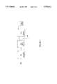
- FIG. 2 shows a block diagram of a closed loop control system of the present invention.
- a liquid crystal display (LCD) backlight integrated circuit controller 100 is shown along with external circuits.
- the integrated circuit controller 100 includes the portion of the diagram enclosed by the dotted lines.
- the controller 100 shown in FIG. 1 and bounded by the dotted lines, is an LCD Backlight Lamp Driver, part number ML4874, manufactured by Micro Linear Corporation, which is located at 2092 Concourse Drive, in San Jose, Calif. Micro Linear Corporation also manufactures an LCD Backlight Lamp Driver with Contrast, part number ML4876 and an LCD Backlight Lamp Driver w/Contrast Control, part number ML4864, which are similar to part number ML4874, except they have circuits to control an LCD contrast level.
- the controller 100 has pins 1-20 that interface with the external circuits.
- a voltage source node Vcc is coupled to pin 12, to a first terminal of a capacitor C7, to a first terminal of a capacitor C8, to a first terminal of a resistor R1, to a drain of an n-channel MOSFET Q1, and to the drain of an n-channel MOSFET U2-A.
- a second terminal of the capacitor C7 is coupled to ground.
- a second terminal of the capacitor C8 is coupled to ground.
- a second terminal of the resistor R1 is coupled to a gate of the MOSFET Q1 and to pin 2.
- a source of the MOSFET Q1 is coupled to pin 13, to a first terminal of a capacitor C10, to a first terminal of a capacitor C1, to a first terminal of a capacitor C9 and to a first terminal of a primary winding of a transformer T2.
- a second terminal of the capacitor C10, a second terminal of the capacitor C1, and a second terminal of the capacitor C9 are coupled to ground.
- a second terminal of the primary winding of the transformer T2 is coupled to pin 19.
- a first terminal of a secondary winding of the transformer T2 is coupled to an anode of a diode D1.
- a second terminal of the secondary winding of the transformer T2 is coupled to a source of the MOSFET U2-A.
- a cathode of the diode D1 is coupled to a gate of the MOSFET U2-A and to a drain of an n-channel MOSFET Q2.
- a source of the MOSFET Q2 is coupled to ground.
- a gate of the MOSFET Q2 is coupled to pin 20.
- a drain of an n-channel MOSFET U2-B is coupled to the source of the MOSFET U2-A.
- a source of the MOSFET U2-B is coupled to ground.
- a gate of the MOSFET U2-B is coupled to pin 11.
- a first terminal of an inductor L1 is coupled to the source of the MOSFET U2-A.
- a second terminal of the inductor L1 is coupled to a first terminal of a resistor R6 and to a center tap of a primary winding of a transformer Ti.
- a second terminal of the resistor R6 is coupled to pin 10.
- a first terminal of a secondary winding of the transformer T1 is coupled to a first terminal of a fluorescent lamp 204.
- a second terminal of the secondary winding of the transformer T1 is coupled to a second terminal of the fluorescent lamp 204.
- a capacitor C11 may be coupled in series with the fluorescent lamp 204, but is not always required.
- a first terminal of the primary winding of the transformer T1 is coupled to a first terminal of a capacitor C6 and to a drain of an n-channel MOSFET Q3.
- a gate of the MOSFET Q3 is coupled to pin 16.
- a source of the MOSFET Q3 is coupled to a first terminal of a resistor R5.
- a second terminal of the first winding of the transformer T1 is coupled to a second terminal of the capacitor C6 and to a drain of an n-channel MOSFET Q4.
- a gate of the MOSFET Q4 is coupled to pin 14.
- a source of the MOSFET Q4 is coupled to the first terminal of the resistor R5.
- the first terminal of the resistor R5 is coupled to pin 6 and to a first terminal of a resistor R3.
- a second terminal of the resistor R3 is coupled to a first terminal of a resistor R4, to a first terminal of a capacitor C4 and to pin 7.
- a second terminal of the resistor R4 is coupled to a voltage level BRIGHTNESS ADJUST.
- a second terminal of the capacitor C4 is coupled to pin 8.
- a first terminal of a capacitor C2 is coupled to pin 3.
- a second terminal of the capacitor C2 is coupled to ground.
- a first terminal of a capacitor C5 is coupled to pin 9.
- a second terminal of the capacitor C5 is coupled to ground.
- a first terminal of a resistor R2 is coupled to pin 4.
- a second terminal of the resistor R2 is coupled to ground.
- Pin 1 is a spare.
- Pin 18 and Pin 17 are coupled to ground.
- Pin 15 is coupled to a voltage level ON/OFF.
- a first terminal of a capacitor C3 is coupled to Pin 15.
- a second terminal of the capacitor C3 is coupled to ground.
- pin 7 is coupled to an inverting input of a amplifier 101.
- a non-inverting input of the amplifier 101 is coupled to a reference voltage level of 0.2 volts.
- a terminal of the amplifier 101 is coupled to pin 3 to couple the optional soft start capacitor C2 to the amplifier 101.
- An output of the amplifier 101 is coupled to pin 8 and to an inverting input of an amplifier 102.
- Pin 9 is coupled to a first terminal of an oscillator 103 to set the oscillation frequency with the timing capacitor C5. Pin 9 is also coupled to a non-inverting input to the amplifier 102.
- An output of the amplifier 102 is coupled to a first input to an OR gate 104.
- An inverting input to an amplifier 105 is coupled to pin 6.
- a non-inverting input to the amplifier 105 is coupled to a voltage reference level of 0.5 volts.
- An output of the amplifier 105 is coupled to a second input to the OR gate 104.
- An output of the OR gate 104 is coupled to a RESET terminal of a flip-flop 106.
- a second terminal of the oscillator 103 is coupled to pin 4 to set the oscillation frequency with the timing resistor R2.
- a third terminal of the oscillator 103 is coupled to deliver a clock signal to a SET terminal of the flip-flop 106, to a first terminal of a one-shot circuit 107 and to a TOGGLE input to a flip-flop 108.
- a second terminal of the one-shot circuit 107 is coupled to an input terminal to a buffer 109.
- An output terminal of the buffer 109 is coupled to pin 19.
- a Q-not output of the flip-flop 106 is coupled to an input to a buffer 110.
- An output of the buffer 110 is coupled to pin 20.
- a Q output of the flip-flop 106 is coupled to an input of a negative edge delay 111.
- An output of the negative edge delay 111 is coupled to an input to a buffer 112.
- An output of the buffer 112 is coupled to pin 11.
- a Q-not output of the flip-flop 108 is coupled to an input to a buffer 113.
- An output of the buffer 113 is coupled to pin 14.
- a Q output of the flip-flop 108 is coupled to an input to a buffer 114.
- An output of the buffer 114 is coupled to pin 16.
- a forth terminal of the oscillator 103 is coupled to receive a signal from a first terminal of a resonant threshold detector 115 to synchronize the oscillator 103.
- Pin 10 is coupled to deliver a zero voltage crossing signal to a second terminal of the resonant threshold detector 115 and to an inverting input to an amplifier 116.
- a non-inverting input to the amplifier 116 is coupled to a reference voltage level of 16 volts.
- An output of the amplifier 116 is coupled to a SET input to a flip-flop 117.
- a Q-not output of the flip-flop 117 is coupled to deliver a control signal to a first terminal of a master bias & uvlo 118 to shut down power to the fluorescent lamp if a voltage at pin 10 exceeds 16 volts.
- a second terminal of the master bias & uvlo 118 is coupled to a RESET input to the flip-flop 117 to restore power to the fluorescent lamp after a shut down by toggling the voltage at pin 15.
- a third terminal of the master bias & uvlo 118 is coupled to deliver a voltage reference level to pin 5.
- a forth terminal of the master bias & uvlo 118 is coupled to receive power from a first terminal of a linear regulator 119.
- a second terminal of the linear regulator 119 is coupled to receive power from pin 12.
- a third terminal of the linear regulator 119 is coupled to pin 2. Internal to the linear regulator 119, the third terminal of the linear regulator 119 is coupled to a cathode of a Zener diode DAZR (not shown). An anode of the Zener diode DAZR, is coupled to ground. A forth terminal of the linear regulator 119 is coupled to pin 13 and coupled to provide a supply voltage to the circuits within the dotted lines.
- An invertor comprises T1, C6, LAMP, Q3, Q4 and R5.
- the inverter is known in the art as comprising a current fed Royer-type inverter.
- a resonant tank circuit comprises C6 and the primary winding of the transformer T1.
- Q3 and Q4 comprise a push-pull transistor pair.
- the controller 100 alternately turns Q3 and Q4 on. This draws current from the resonant tank circuit which in turn generates a voltage across the secondary winding of T1 to power the lamp.
- the controller turns on either Q3 or Q4 and turns off the other. Because the controller alternates only at zero crossings, the tank circuit is driven at its resonant frequency.
- An internal oscillator 103 provides the switching signals for start-up.
- the current drawn by Q3 and Q4 is substantially proportional to the current through the lamp.
- the current through the inverter generates a voltage at Pin 7 which is sensed and monitored by the controller so the lamp current can be monitored for controlling the lamp brightness.
- the voltage at the node that comprises the source of Q3, the source of Q4 and the first terminal of R5 is coupled to the inverting input of the amplifier 101 through R3.
- the output of the amplifier 101 is coupled to control the duty cycle of the buck regulator.
- the inverter does not regulate the lamp brightness by varying the switching frequency because the inverter drives the lamp at the resonant frequency of the tank circuit.
- a buck regulator having a high side driver comprises T2, D1, U2-A, Q2 and L1.
- the buck regulator provides a square wave buck current signal to the inverter circuit though L1.
- the lamp brightness is regulated by a duty cycle of the buck signal and is controllable by the controller by switching U2-A and Q2.
- U2-A is the main power switch of the high side driver for driving the inductor L1 and the inverter circuit.
- U2-A has a high current capacity, and in the preferred embodiment, is a Dual 20 v, 0.10 Ohm, n-channel, MOSFET transistor manufactured by Motorola, under part number MMDF2N02.
- the controller drives the gate of U2-A through the miniature pulse transformer T2.
- T2 can be made with a ferrite bead with one turn on the primary winding and two turns on the secondary winding.
- T2 may be a low cost, surface mount transformer, such as part number CP-4LBM, which is available from Sumida, 637 East Golf Road, Suite 209, Arlington Heights, Ill., 60005.
- a controller output When a controller output, a signal B-ON, is activated, the voltage generated at the secondary winding of T2 is greater than the voltage level of the signal B-ON because of the transformer.
- B-ON is a logic level voltage of approximately 5 volts.
- the diode D1 When the signal B-ON is activated, the diode D1 becomes forward biased so that the gate of U2-A becomes charged to a higher potential than B-ON (to approximately 10 volts).
- B-ON When B-ON is de-activated, the diode D1 then becomes reverse biased which captures the charge on the gate of U2-A because of the channel of the transistor Q2 so that there is no path for discharging this gate and thus keeps U2-A turned on.
- the gate of Q2 When the signal B-OFF is activated, the gate of Q2, a small signal device, is driven high by the controller. This turns Q2 on and causes the charge captured on the gate of U2-A to drain off to ground through Q2, turning U2-A off. By alternately activating B-ON and B-OFF, a current signal having a controllable duty cycle is generated.
- a reference signal 200 is supplied to a controller 201 to control a brightness level of the lamp 204.
- a feedback signal 205 is also supplied to the controller 201.
- the controller 201 controls a duty cycle of a buck regulator 202 based on the reference signal 200 and a feedback signal 205.
- the buck regulator 202 supplies current to an inverter 203 which powers the lamp 204.
- a current in the lamp is sensed and fed back to the controller 201 through the feedback signal 205 that is representative of the current in the lamp.
Abstract
Description
Claims (33)
Priority Applications (1)
| Application Number | Priority Date | Filing Date | Title |
|---|---|---|---|
| US08/726,970 US5754012A (en) | 1995-01-25 | 1996-10-07 | Primary side lamp current sensing for minature cold cathode fluorescent lamp system |
Applications Claiming Priority (2)
| Application Number | Priority Date | Filing Date | Title |
|---|---|---|---|
| US37764495A | 1995-01-25 | 1995-01-25 | |
| US08/726,970 US5754012A (en) | 1995-01-25 | 1996-10-07 | Primary side lamp current sensing for minature cold cathode fluorescent lamp system |
Related Parent Applications (1)
| Application Number | Title | Priority Date | Filing Date |
|---|---|---|---|
| US37764495A Continuation | 1995-01-25 | 1995-01-25 |
Publications (1)
| Publication Number | Publication Date |
|---|---|
| US5754012A true US5754012A (en) | 1998-05-19 |
Family
ID=23489957
Family Applications (1)
| Application Number | Title | Priority Date | Filing Date |
|---|---|---|---|
| US08/726,970 Expired - Lifetime US5754012A (en) | 1995-01-25 | 1996-10-07 | Primary side lamp current sensing for minature cold cathode fluorescent lamp system |
Country Status (1)
| Country | Link |
|---|---|
| US (1) | US5754012A (en) |
Cited By (32)
| Publication number | Priority date | Publication date | Assignee | Title |
|---|---|---|---|---|
| US6114814A (en) * | 1998-12-11 | 2000-09-05 | Monolithic Power Systems, Inc. | Apparatus for controlling a discharge lamp in a backlighted display |
| US6130509A (en) * | 1999-01-22 | 2000-10-10 | Dell Computer Corporation | Balanced feedback system for floating cold cathode fluorescent lamps |
| US6181071B1 (en) * | 1997-02-28 | 2001-01-30 | Mitsubishi Denki Kabushiki Kaisha | Display panel apparatus having reduced capacitive coupling |
| WO2002001924A2 (en) * | 2000-06-27 | 2002-01-03 | Maxim Integrated Products, Inc. | Cold cathode fluorescent lamp controller |
| WO2002023301A1 (en) * | 2000-09-15 | 2002-03-21 | Radian Research, Inc. | Wide ratio autotransformer-type current ranging |
| US6392355B1 (en) | 2000-04-25 | 2002-05-21 | Mcnc | Closed-loop cold cathode current regulator |
| GB2372161A (en) * | 2000-10-25 | 2002-08-14 | Raymarine Ltd | Fluorescent lamp driver circuit |
| US6479947B1 (en) | 2000-10-13 | 2002-11-12 | Donald Ellis Newsome | Ultraviolet fluorescent lamp with unique drive circuit |
| US20030137382A1 (en) * | 2001-12-03 | 2003-07-24 | Mayfield Glenn A. | Transformers |
| US20030164815A1 (en) * | 2002-03-01 | 2003-09-04 | Fujitsu Display Technologies Corporation | Back light and liquid crystal display |
| US6856519B2 (en) | 2002-05-06 | 2005-02-15 | O2Micro International Limited | Inverter controller |
| US20050062436A1 (en) * | 2003-09-09 | 2005-03-24 | Xiaoping Jin | Split phase inverters for CCFL backlight system |
| US20050088115A1 (en) * | 2002-03-27 | 2005-04-28 | Sanken Electric Co., Ltd | Cold-cathode tube operating appratus |
| US20050093484A1 (en) * | 2003-10-21 | 2005-05-05 | Ball Newton E. | Systems and methods for fault protection in a balancing transformer |
| US20050093472A1 (en) * | 2003-10-06 | 2005-05-05 | Xiaoping Jin | Balancing transformers for ring balancer |
| US20050140313A1 (en) * | 2003-10-02 | 2005-06-30 | Monolithic Power Systems, Inc. | Fixed operating frequency inverter for cold cathode fluorescent lamp having strike frequency adjusted by voltage to current phase relationship |
| US20050156536A1 (en) * | 2003-12-16 | 2005-07-21 | Ball Newton E. | Method and apparatus to drive LED arrays using time sharing technique |
| US6940233B2 (en) | 2002-10-03 | 2005-09-06 | Analog Microelectronics, Inc. | Method and system of driving a CCFL |
| US20050225261A1 (en) * | 2004-04-07 | 2005-10-13 | Xiaoping Jin | Primary side current balancing scheme for multiple CCF lamp operation |
| US20060220593A1 (en) * | 2005-03-31 | 2006-10-05 | Ball Newton E | Nested balancing topology for balancing current among multiple lamps |
| US20080012507A1 (en) * | 2006-07-07 | 2008-01-17 | Mehmet Nalbant | High Current Fast Rise And Fall Time LED Driver |
| US7355354B2 (en) | 1998-12-11 | 2008-04-08 | Monolithic Power Systems, Inc. | Method for starting a discharge lamp using high energy initial pulse |
| US20090261747A1 (en) * | 2006-09-18 | 2009-10-22 | Himax Technologies Limited | Control system for multiple fluorescent lamps |
| US7646152B2 (en) | 2004-04-01 | 2010-01-12 | Microsemi Corporation | Full-bridge and half-bridge compatible driver timing schedule for direct drive backlight system |
| US7755595B2 (en) | 2004-06-07 | 2010-07-13 | Microsemi Corporation | Dual-slope brightness control for transflective displays |
| US7977888B2 (en) | 2003-10-06 | 2011-07-12 | Microsemi Corporation | Direct coupled balancer drive for floating lamp structure |
| US8093839B2 (en) | 2008-11-20 | 2012-01-10 | Microsemi Corporation | Method and apparatus for driving CCFL at low burst duty cycle rates |
| US8223117B2 (en) | 2004-02-09 | 2012-07-17 | Microsemi Corporation | Method and apparatus to control display brightness with ambient light correction |
| US8358082B2 (en) | 2006-07-06 | 2013-01-22 | Microsemi Corporation | Striking and open lamp regulation for CCFL controller |
| US8598795B2 (en) | 2011-05-03 | 2013-12-03 | Microsemi Corporation | High efficiency LED driving method |
| US8754581B2 (en) | 2011-05-03 | 2014-06-17 | Microsemi Corporation | High efficiency LED driving method for odd number of LED strings |
| US9030119B2 (en) | 2010-07-19 | 2015-05-12 | Microsemi Corporation | LED string driver arrangement with non-dissipative current balancer |
Citations (87)
| Publication number | Priority date | Publication date | Assignee | Title |
|---|---|---|---|---|
| US2483815A (en) * | 1946-03-14 | 1949-10-04 | Easton Bertie | Electrical plug and jack connection |
| US2967267A (en) * | 1958-03-26 | 1961-01-03 | Litton Systems Inc | Reactive intercoupling of modular units |
| US3292579A (en) * | 1965-06-24 | 1966-12-20 | Beverly J Buchanan | Aquarium power supply |
| US3549990A (en) * | 1968-08-19 | 1970-12-22 | Jerome S Hochheiser | Non-sparking a-c connectors |
| US3611021A (en) * | 1970-04-06 | 1971-10-05 | North Electric Co | Control circuit for providing regulated current to lamp load |
| US3758823A (en) * | 1971-12-23 | 1973-09-11 | Jettson Engineering Co Inc | Battery powered fluorescent light |
| US3772625A (en) * | 1971-05-17 | 1973-11-13 | E Raupach | Transformer for producing or measuring high and very high potentials or for measuring currents at high potentials in cascade connection |
| US3778677A (en) * | 1972-08-25 | 1973-12-11 | Lowrance Electronics Mfg | Inverter ballast circuit |
| US3828203A (en) * | 1970-03-24 | 1974-08-06 | Honeywell Inc | Ramped-step signal generating circuit |
| US3840795A (en) * | 1964-07-07 | 1974-10-08 | Sunbeam Corp | Hand held battery operated device and charging means therefor |
| US3893036A (en) * | 1973-07-27 | 1975-07-01 | Tektronix Inc | Precision function generator |
| US3921005A (en) * | 1974-12-19 | 1975-11-18 | Gen Electric | Emergency lighting system with high efficiency inverter |
| US3953768A (en) * | 1970-12-23 | 1976-04-27 | Meredith Ronald D | Portable fluorescent lamp and inverter therefor |
| US4030058A (en) * | 1976-03-30 | 1977-06-14 | Westinghouse Electric Corporation | Inductive coupler |
| US4031449A (en) * | 1975-11-20 | 1977-06-21 | Arthur D. Little, Inc. | Electromagnetically coupled battery charger |
| US4038625A (en) * | 1976-06-07 | 1977-07-26 | General Electric Company | Magnetic inductively-coupled connector |
| US4063108A (en) * | 1976-01-02 | 1977-12-13 | Keith Karl Klett | Inverter lockout circuit |
| US4144462A (en) * | 1977-04-28 | 1979-03-13 | Dual-Lite, Inc. | Emergency lighting fluorescent pack |
| US4146857A (en) * | 1976-11-10 | 1979-03-27 | Robert Bosch Gmbh | Ignition coil for engine ignition system |
| US4172981A (en) * | 1978-06-15 | 1979-10-30 | Francis H. Harrington | Lighting system |
| US4207498A (en) * | 1978-12-05 | 1980-06-10 | Lutron Electronics Co., Inc. | System for energizing and dimming gas discharge lamps |
| US4210846A (en) * | 1978-12-05 | 1980-07-01 | Lutron Electronics Co., Inc. | Inverter circuit for energizing and dimming gas discharge lamps |
| US4225825A (en) * | 1978-09-25 | 1980-09-30 | Beckman Instruments, Inc. | Precision self-adjusting slope circuit |
| US4251752A (en) * | 1979-05-07 | 1981-02-17 | Synergetics, Inc. | Solid state electronic ballast system for fluorescent lamps |
| US4260943A (en) * | 1979-01-30 | 1981-04-07 | Unitron Corporation | High frequency battery charger |
| US4277728A (en) * | 1978-05-08 | 1981-07-07 | Stevens Luminoptics | Power supply for a high intensity discharge or fluorescent lamp |
| US4277726A (en) * | 1978-08-28 | 1981-07-07 | Litton Systems, Inc. | Solid-state ballast for rapid-start type fluorescent lamps |
| US4297614A (en) * | 1980-03-12 | 1981-10-27 | Kaufel Group Ltd. | Emergency lighting system |
| US4303902A (en) * | 1979-08-31 | 1981-12-01 | Westinghouse Electric Corp. | Inductive coupler |
| US4318608A (en) * | 1977-01-05 | 1982-03-09 | Payne John M | Portable electrostatic photocopier |
| DE3233655A1 (en) * | 1981-09-11 | 1983-05-05 | Zumtobel AG, 6850 Dornbirn | Electronic ballast for a fluorescent or gas-discharge tube |
| US4390844A (en) * | 1980-12-24 | 1983-06-28 | California Institute Of Technology | Integration filter for step waveforms |
| US4414493A (en) * | 1981-10-06 | 1983-11-08 | Thomas Industries Inc. | Light dimmer for solid state ballast |
| US4441054A (en) * | 1982-04-12 | 1984-04-03 | Gte Products Corporation | Stabilized dimming circuit for lamp ballasts |
| US4441053A (en) * | 1981-11-27 | 1984-04-03 | Data-Design Laboratories | Switched mode electrode ballast |
| US4453109A (en) * | 1982-05-27 | 1984-06-05 | North American Philips Corporation | Magnetic transformer switch and combination thereof with a discharge lamp |
| US4486689A (en) * | 1983-02-18 | 1984-12-04 | George W. Plumly | Emergency lighting apparatus and systems |
| US4495446A (en) * | 1982-12-27 | 1985-01-22 | General Electric Company | Lighting unit with improved control sequence |
| US4496896A (en) * | 1983-04-14 | 1985-01-29 | Towmotor Corporation | Vehicle battery charging apparatus |
| US4498031A (en) * | 1983-01-03 | 1985-02-05 | North American Philips Corporation | Variable frequency current control device for discharge lamps |
| DE3432266A1 (en) * | 1983-09-06 | 1985-03-21 | F. Knobel Elektro-Apparatebau AG, Ennenda | Electronic ballast for fluorescent lamps, and a method for its operation |
| US4523131A (en) * | 1982-12-10 | 1985-06-11 | Honeywell Inc. | Dimmable electronic gas discharge lamp ballast |
| US4528482A (en) * | 1983-07-20 | 1985-07-09 | Merlo Joseph C | Control of energy to fluorescent lighting |
| US4543556A (en) * | 1983-07-29 | 1985-09-24 | Marconi Avionics Limited | Inductive coupler systems |
| EP0059064B1 (en) * | 1981-02-21 | 1985-10-02 | THORN EMI plc | Lamp driver circuits |
| US4572988A (en) * | 1983-08-22 | 1986-02-25 | Industrial Design Associates, (Ida) | High frequency ballast circuit |
| EP0178852A1 (en) * | 1984-10-16 | 1986-04-23 | ADVANCE TRANSFORMER CO. (a Division of Philips Electronics North America Corporation) | Electronic ballast circuit for fluorescent lamps |
| US4585974A (en) * | 1983-01-03 | 1986-04-29 | North American Philips Corporation | Varible frequency current control device for discharge lamps |
| US4604552A (en) * | 1984-08-30 | 1986-08-05 | General Electric Company | Retrofit fluorescent lamp energy management/dimming system |
| US4612479A (en) * | 1984-07-20 | 1986-09-16 | Honeywell Inc. | Fluorescent light controller |
| US4654573A (en) * | 1985-05-17 | 1987-03-31 | Flexible Manufacturing Systems, Inc. | Power transfer device |
| US4686427A (en) * | 1985-08-13 | 1987-08-11 | Magnetek, Inc. | Fluorescent lamp dimming switch |
| US4698554A (en) * | 1983-01-03 | 1987-10-06 | North American Philips Corporation | Variable frequency current control device for discharge lamps |
| US4700113A (en) * | 1981-12-28 | 1987-10-13 | North American Philips Corporation | Variable high frequency ballast circuit |
| US4704563A (en) * | 1986-05-09 | 1987-11-03 | General Electric Company | Fluorescent lamp operating circuit |
| US4717863A (en) * | 1986-02-18 | 1988-01-05 | Zeiler Kenneth T | Frequency modulation ballast circuit |
| US4723098A (en) * | 1980-10-07 | 1988-02-02 | Thomas Industries, Inc. | Electronic ballast circuit for fluorescent lamps |
| US4739277A (en) * | 1986-03-03 | 1988-04-19 | Tektronix, Inc. | Triggered, programmable skew signal generator |
| US4763239A (en) * | 1985-06-04 | 1988-08-09 | Thorn Emi Lighting (Nz) Limited | Switched mode power supplies |
| US4800328A (en) * | 1986-07-18 | 1989-01-24 | Inductran Inc. | Inductive power coupling with constant voltage output |
| US4874989A (en) * | 1986-12-11 | 1989-10-17 | Nilssen Ole K | Electronic ballast unit with integral light sensor and circuit |
| US4893059A (en) * | 1986-02-19 | 1990-01-09 | Nilssen Ole K | Electronic ballast with safety feature |
| US4896077A (en) * | 1987-06-16 | 1990-01-23 | Cooper Industries, Inc. | Ignitor disabler |
| US4920299A (en) * | 1988-04-27 | 1990-04-24 | General Electric Company | Push-pull fluorescent dimming circuit |
| US4935669A (en) * | 1988-01-20 | 1990-06-19 | Nilssen Ole K | Two-mode electronic ballast |
| US4942352A (en) * | 1988-09-09 | 1990-07-17 | Toppan Moore Co., Ltd. | Non-contacting power supplying system |
| US4952849A (en) * | 1988-07-15 | 1990-08-28 | North American Philips Corporation | Fluorescent lamp controllers |
| US5015919A (en) * | 1989-07-19 | 1991-05-14 | Led Corporation N.V. | Emergency lighting system provided with a fluorescent tube |
| US5048033A (en) * | 1990-09-04 | 1991-09-10 | Coherent, Inc. | Method and apparatus for controlling the power supply of a laser operating in a pulse mode |
| US5049790A (en) * | 1988-09-23 | 1991-09-17 | Siemens Aktiengesellschaft | Method and apparatus for operating at least one gas discharge lamp |
| WO1992001334A1 (en) * | 1987-12-11 | 1992-01-23 | Murray Scott V | Magnetic structure and power converter for light sources |
| US5111118A (en) * | 1988-07-15 | 1992-05-05 | North American Philips Corporation | Fluorescent lamp controllers |
| US5177408A (en) * | 1991-07-19 | 1993-01-05 | Magnetek Triad | Startup circuit for electronic ballasts for instant-start lamps |
| US5202608A (en) * | 1991-03-26 | 1993-04-13 | National Service Industries, Inc. | Emergency lighting system utilizing improved and rapidly installable fluorescent inverter |
| US5214352A (en) * | 1991-06-07 | 1993-05-25 | Computer Power Inc. | Light dimming system for emergency operation |
| US5216402A (en) * | 1992-01-22 | 1993-06-01 | Hughes Aircraft Company | Separable inductive coupler |
| US5237242A (en) * | 1990-12-30 | 1993-08-17 | Toshiba Lighting And Technology Corporation | Apparatus for operating a discharge lamp and a lighting unit having the apparatus |
| US5264776A (en) * | 1992-06-30 | 1993-11-23 | Hughes Aircraft Company | Electric vehicle inductive coupling charge port |
| US5363020A (en) * | 1993-02-05 | 1994-11-08 | Systems And Service International, Inc. | Electronic power controller |
| US5367224A (en) * | 1991-08-27 | 1994-11-22 | Everbrite, Inc. | High frequency luminous tube power supply having neon-bubble and mercury-migration suppression |
| US5367223A (en) * | 1991-12-30 | 1994-11-22 | Hewlett-Packard Company | Fluoresent lamp current level controller |
| US5367242A (en) * | 1991-09-20 | 1994-11-22 | Ericsson Radio Systems B.V. | System for charging a rechargeable battery of a portable unit in a rack |
| US5384516A (en) * | 1991-11-06 | 1995-01-24 | Hitachi, Ltd. | Information processing apparatus including a control circuit for controlling a liquid crystal display illumination based on whether illuminatio power is being supplied from an AC power source or from a battery |
| US5394020A (en) * | 1992-12-30 | 1995-02-28 | Zenith Electronics Corporation | Vertical ramp automatic amplitude control |
| US5408162A (en) * | 1992-03-26 | 1995-04-18 | Linear Technology Corporation | Fluorescent lamp power supply and control unit |
| US5615093A (en) * | 1994-08-05 | 1997-03-25 | Linfinity Microelectronics | Current synchronous zero voltage switching resonant topology |
| US5642066A (en) * | 1995-05-24 | 1997-06-24 | Ail System, Inc. | Linear ramp generator having two voltage controlled current sources |
-
1996
- 1996-10-07 US US08/726,970 patent/US5754012A/en not_active Expired - Lifetime
Patent Citations (87)
| Publication number | Priority date | Publication date | Assignee | Title |
|---|---|---|---|---|
| US2483815A (en) * | 1946-03-14 | 1949-10-04 | Easton Bertie | Electrical plug and jack connection |
| US2967267A (en) * | 1958-03-26 | 1961-01-03 | Litton Systems Inc | Reactive intercoupling of modular units |
| US3840795A (en) * | 1964-07-07 | 1974-10-08 | Sunbeam Corp | Hand held battery operated device and charging means therefor |
| US3292579A (en) * | 1965-06-24 | 1966-12-20 | Beverly J Buchanan | Aquarium power supply |
| US3549990A (en) * | 1968-08-19 | 1970-12-22 | Jerome S Hochheiser | Non-sparking a-c connectors |
| US3828203A (en) * | 1970-03-24 | 1974-08-06 | Honeywell Inc | Ramped-step signal generating circuit |
| US3611021A (en) * | 1970-04-06 | 1971-10-05 | North Electric Co | Control circuit for providing regulated current to lamp load |
| US3953768A (en) * | 1970-12-23 | 1976-04-27 | Meredith Ronald D | Portable fluorescent lamp and inverter therefor |
| US3772625A (en) * | 1971-05-17 | 1973-11-13 | E Raupach | Transformer for producing or measuring high and very high potentials or for measuring currents at high potentials in cascade connection |
| US3758823A (en) * | 1971-12-23 | 1973-09-11 | Jettson Engineering Co Inc | Battery powered fluorescent light |
| US3778677A (en) * | 1972-08-25 | 1973-12-11 | Lowrance Electronics Mfg | Inverter ballast circuit |
| US3893036A (en) * | 1973-07-27 | 1975-07-01 | Tektronix Inc | Precision function generator |
| US3921005A (en) * | 1974-12-19 | 1975-11-18 | Gen Electric | Emergency lighting system with high efficiency inverter |
| US4031449A (en) * | 1975-11-20 | 1977-06-21 | Arthur D. Little, Inc. | Electromagnetically coupled battery charger |
| US4063108A (en) * | 1976-01-02 | 1977-12-13 | Keith Karl Klett | Inverter lockout circuit |
| US4030058A (en) * | 1976-03-30 | 1977-06-14 | Westinghouse Electric Corporation | Inductive coupler |
| US4038625A (en) * | 1976-06-07 | 1977-07-26 | General Electric Company | Magnetic inductively-coupled connector |
| US4146857A (en) * | 1976-11-10 | 1979-03-27 | Robert Bosch Gmbh | Ignition coil for engine ignition system |
| US4318608A (en) * | 1977-01-05 | 1982-03-09 | Payne John M | Portable electrostatic photocopier |
| US4144462A (en) * | 1977-04-28 | 1979-03-13 | Dual-Lite, Inc. | Emergency lighting fluorescent pack |
| US4277728A (en) * | 1978-05-08 | 1981-07-07 | Stevens Luminoptics | Power supply for a high intensity discharge or fluorescent lamp |
| US4172981A (en) * | 1978-06-15 | 1979-10-30 | Francis H. Harrington | Lighting system |
| US4277726A (en) * | 1978-08-28 | 1981-07-07 | Litton Systems, Inc. | Solid-state ballast for rapid-start type fluorescent lamps |
| US4225825A (en) * | 1978-09-25 | 1980-09-30 | Beckman Instruments, Inc. | Precision self-adjusting slope circuit |
| US4210846A (en) * | 1978-12-05 | 1980-07-01 | Lutron Electronics Co., Inc. | Inverter circuit for energizing and dimming gas discharge lamps |
| US4207498A (en) * | 1978-12-05 | 1980-06-10 | Lutron Electronics Co., Inc. | System for energizing and dimming gas discharge lamps |
| US4260943A (en) * | 1979-01-30 | 1981-04-07 | Unitron Corporation | High frequency battery charger |
| US4251752A (en) * | 1979-05-07 | 1981-02-17 | Synergetics, Inc. | Solid state electronic ballast system for fluorescent lamps |
| US4303902A (en) * | 1979-08-31 | 1981-12-01 | Westinghouse Electric Corp. | Inductive coupler |
| US4297614A (en) * | 1980-03-12 | 1981-10-27 | Kaufel Group Ltd. | Emergency lighting system |
| US4723098A (en) * | 1980-10-07 | 1988-02-02 | Thomas Industries, Inc. | Electronic ballast circuit for fluorescent lamps |
| US4390844A (en) * | 1980-12-24 | 1983-06-28 | California Institute Of Technology | Integration filter for step waveforms |
| EP0059064B1 (en) * | 1981-02-21 | 1985-10-02 | THORN EMI plc | Lamp driver circuits |
| DE3233655A1 (en) * | 1981-09-11 | 1983-05-05 | Zumtobel AG, 6850 Dornbirn | Electronic ballast for a fluorescent or gas-discharge tube |
| US4414493A (en) * | 1981-10-06 | 1983-11-08 | Thomas Industries Inc. | Light dimmer for solid state ballast |
| US4441053A (en) * | 1981-11-27 | 1984-04-03 | Data-Design Laboratories | Switched mode electrode ballast |
| US4700113A (en) * | 1981-12-28 | 1987-10-13 | North American Philips Corporation | Variable high frequency ballast circuit |
| US4441054A (en) * | 1982-04-12 | 1984-04-03 | Gte Products Corporation | Stabilized dimming circuit for lamp ballasts |
| US4453109A (en) * | 1982-05-27 | 1984-06-05 | North American Philips Corporation | Magnetic transformer switch and combination thereof with a discharge lamp |
| US4523131A (en) * | 1982-12-10 | 1985-06-11 | Honeywell Inc. | Dimmable electronic gas discharge lamp ballast |
| US4495446A (en) * | 1982-12-27 | 1985-01-22 | General Electric Company | Lighting unit with improved control sequence |
| US4498031A (en) * | 1983-01-03 | 1985-02-05 | North American Philips Corporation | Variable frequency current control device for discharge lamps |
| US4585974A (en) * | 1983-01-03 | 1986-04-29 | North American Philips Corporation | Varible frequency current control device for discharge lamps |
| US4698554A (en) * | 1983-01-03 | 1987-10-06 | North American Philips Corporation | Variable frequency current control device for discharge lamps |
| US4486689A (en) * | 1983-02-18 | 1984-12-04 | George W. Plumly | Emergency lighting apparatus and systems |
| US4496896A (en) * | 1983-04-14 | 1985-01-29 | Towmotor Corporation | Vehicle battery charging apparatus |
| US4528482A (en) * | 1983-07-20 | 1985-07-09 | Merlo Joseph C | Control of energy to fluorescent lighting |
| US4543556A (en) * | 1983-07-29 | 1985-09-24 | Marconi Avionics Limited | Inductive coupler systems |
| US4572988A (en) * | 1983-08-22 | 1986-02-25 | Industrial Design Associates, (Ida) | High frequency ballast circuit |
| DE3432266A1 (en) * | 1983-09-06 | 1985-03-21 | F. Knobel Elektro-Apparatebau AG, Ennenda | Electronic ballast for fluorescent lamps, and a method for its operation |
| US4612479A (en) * | 1984-07-20 | 1986-09-16 | Honeywell Inc. | Fluorescent light controller |
| US4604552A (en) * | 1984-08-30 | 1986-08-05 | General Electric Company | Retrofit fluorescent lamp energy management/dimming system |
| EP0178852A1 (en) * | 1984-10-16 | 1986-04-23 | ADVANCE TRANSFORMER CO. (a Division of Philips Electronics North America Corporation) | Electronic ballast circuit for fluorescent lamps |
| US4654573A (en) * | 1985-05-17 | 1987-03-31 | Flexible Manufacturing Systems, Inc. | Power transfer device |
| US4763239A (en) * | 1985-06-04 | 1988-08-09 | Thorn Emi Lighting (Nz) Limited | Switched mode power supplies |
| US4686427A (en) * | 1985-08-13 | 1987-08-11 | Magnetek, Inc. | Fluorescent lamp dimming switch |
| US4717863A (en) * | 1986-02-18 | 1988-01-05 | Zeiler Kenneth T | Frequency modulation ballast circuit |
| US4893059A (en) * | 1986-02-19 | 1990-01-09 | Nilssen Ole K | Electronic ballast with safety feature |
| US4739277A (en) * | 1986-03-03 | 1988-04-19 | Tektronix, Inc. | Triggered, programmable skew signal generator |
| US4704563A (en) * | 1986-05-09 | 1987-11-03 | General Electric Company | Fluorescent lamp operating circuit |
| US4800328A (en) * | 1986-07-18 | 1989-01-24 | Inductran Inc. | Inductive power coupling with constant voltage output |
| US4874989A (en) * | 1986-12-11 | 1989-10-17 | Nilssen Ole K | Electronic ballast unit with integral light sensor and circuit |
| US4896077A (en) * | 1987-06-16 | 1990-01-23 | Cooper Industries, Inc. | Ignitor disabler |
| WO1992001334A1 (en) * | 1987-12-11 | 1992-01-23 | Murray Scott V | Magnetic structure and power converter for light sources |
| US4935669A (en) * | 1988-01-20 | 1990-06-19 | Nilssen Ole K | Two-mode electronic ballast |
| US4920299A (en) * | 1988-04-27 | 1990-04-24 | General Electric Company | Push-pull fluorescent dimming circuit |
| US4952849A (en) * | 1988-07-15 | 1990-08-28 | North American Philips Corporation | Fluorescent lamp controllers |
| US5111118A (en) * | 1988-07-15 | 1992-05-05 | North American Philips Corporation | Fluorescent lamp controllers |
| US4942352A (en) * | 1988-09-09 | 1990-07-17 | Toppan Moore Co., Ltd. | Non-contacting power supplying system |
| US5049790A (en) * | 1988-09-23 | 1991-09-17 | Siemens Aktiengesellschaft | Method and apparatus for operating at least one gas discharge lamp |
| US5015919A (en) * | 1989-07-19 | 1991-05-14 | Led Corporation N.V. | Emergency lighting system provided with a fluorescent tube |
| US5048033A (en) * | 1990-09-04 | 1991-09-10 | Coherent, Inc. | Method and apparatus for controlling the power supply of a laser operating in a pulse mode |
| US5237242A (en) * | 1990-12-30 | 1993-08-17 | Toshiba Lighting And Technology Corporation | Apparatus for operating a discharge lamp and a lighting unit having the apparatus |
| US5202608A (en) * | 1991-03-26 | 1993-04-13 | National Service Industries, Inc. | Emergency lighting system utilizing improved and rapidly installable fluorescent inverter |
| US5214352A (en) * | 1991-06-07 | 1993-05-25 | Computer Power Inc. | Light dimming system for emergency operation |
| US5177408A (en) * | 1991-07-19 | 1993-01-05 | Magnetek Triad | Startup circuit for electronic ballasts for instant-start lamps |
| US5367224A (en) * | 1991-08-27 | 1994-11-22 | Everbrite, Inc. | High frequency luminous tube power supply having neon-bubble and mercury-migration suppression |
| US5367242A (en) * | 1991-09-20 | 1994-11-22 | Ericsson Radio Systems B.V. | System for charging a rechargeable battery of a portable unit in a rack |
| US5384516A (en) * | 1991-11-06 | 1995-01-24 | Hitachi, Ltd. | Information processing apparatus including a control circuit for controlling a liquid crystal display illumination based on whether illuminatio power is being supplied from an AC power source or from a battery |
| US5367223A (en) * | 1991-12-30 | 1994-11-22 | Hewlett-Packard Company | Fluoresent lamp current level controller |
| US5216402A (en) * | 1992-01-22 | 1993-06-01 | Hughes Aircraft Company | Separable inductive coupler |
| US5408162A (en) * | 1992-03-26 | 1995-04-18 | Linear Technology Corporation | Fluorescent lamp power supply and control unit |
| US5264776A (en) * | 1992-06-30 | 1993-11-23 | Hughes Aircraft Company | Electric vehicle inductive coupling charge port |
| US5394020A (en) * | 1992-12-30 | 1995-02-28 | Zenith Electronics Corporation | Vertical ramp automatic amplitude control |
| US5363020A (en) * | 1993-02-05 | 1994-11-08 | Systems And Service International, Inc. | Electronic power controller |
| US5615093A (en) * | 1994-08-05 | 1997-03-25 | Linfinity Microelectronics | Current synchronous zero voltage switching resonant topology |
| US5642066A (en) * | 1995-05-24 | 1997-06-24 | Ail System, Inc. | Linear ramp generator having two voltage controlled current sources |
Non-Patent Citations (26)
| Title |
|---|
| J. Williams, "Techniques for 92% Efficient LCD Illumination" Linear Technology Application Note 55, pp. AN55-1-43, Aug. 1993. |
| J. Williams, Techniques for 92% Efficient LCD Illumination Linear Technology Application Note 55, pp. AN55 1 43, Aug. 1993. * |
| J.J. LoCascio and U. H. Mader, New Control Technique Uses 25% Less Power To Drive Miniature Cold Cathode Fluorescent Lamps, Electronic Ballast , pp. 60 69, Apr. 1994. * |
| J.J. LoCascio and U. H. Mader,"New Control Technique Uses 25% Less Power To Drive Miniature Cold Cathode Fluorescent Lamps," Electronic Ballast, pp. 60-69, Apr. 1994. |
| K. Kit Sum, et al., Micro Linear, "Application Note 32 -Theory and Application of the ML4874 and ML4876 LCD Backlight Controller ICs," pp. 1-12, Jun. 1994. |
| K. Kit Sum, et al., Micro Linear, Application Note 32 Theory and Application of the ML4874 and ML4876 LCD Backlight Controller ICs, pp. 1 12, Jun. 1994. * |
| K. Kit Sum, Micro Linear, "ML4874 Evaluation Kit User's Guide -LCD Backlight Lamp Driver," pp. 1-5, Apr. 1994. |
| K. Kit Sum, Micro Linear, ML4874 Evaluation Kit User s Guide LCD Backlight Lamp Driver, pp. 1 5, Apr. 1994. * |
| M. Jordan and J.A. O Connor, Resonant Fluorescent Lamp Converter Provides Efficient and Compact Solution, IEEE , pp. 424 431, 1993. * |
| M. Jordan and J.A. O'Connor, "Resonant Fluorescent Lamp Converter Provides Efficient and Compact Solution," IEEE, pp. 424-431, 1993. |
| Maxim Integrated Products, "CCFT Backlight and LCD Contrast Controllers -MAX753/MAX754," pp. 1-12, Feb. 1994. |
| Maxim Integrated Products, CCFT Backlight and LCD Contrast Controllers MAX753/MAX754, pp. 1 12, Feb. 1994. * |
| Micro Linear, "Advance Information ML-4830 Electronic Ballast Controller", Jun. 1992. |
| Micro Linear, "ML 4876 LCD Backlight Lamp Driver with Contrast,"pp. 1-6, Apr. 1994. |
| Micro Linear, "ML4864 Evaluation User's Guide -LCD Backlight Lamp Driver with Contrast Control," pp. 1-4, Jan. 1994. |
| Micro Linear, "ML4864 LCD Backlight Lamp Driver with Contrast Control," pp. 1-6, Nov. 1993. |
| Micro Linear, "ML4874 LCD Backlight Lamp Driver,"pp. 1-6, Apr. 1994. |
| Micro Linear, Advance Information ML 4830 Electronic Ballast Controller , Jun. 1992. * |
| Micro Linear, Application Note 24 , p. 3. * |
| Micro Linear, ML 4876 LCD Backlight Lamp Driver with Contrast, pp. 1 6, Apr. 1994. * |
| Micro Linear, ML4864 Evaluation User s Guide LCD Backlight Lamp Driver with Contrast Control, pp. 1 4, Jan. 1994. * |
| Micro Linear, ML4864 LCD Backlight Lamp Driver with Contrast Control, pp. 1 6, Nov. 1993. * |
| Micro Linear, ML4874 LCD Backlight Lamp Driver, pp. 1 6, Apr. 1994. * |
| Micro Linear,"Application Note 24", p. 3. |
| U. Mader, et al., Micro Linear, "Application Note 26 -Power Conversion Efficiencies for Miniature Fluorescent Lamp," pp. 1-6, Feb. 1994. |
| U. Mader, et al., Micro Linear, Application Note 26 Power Conversion Efficiencies for Miniature Fluorescent Lamp, pp. 1 6, Feb. 1994. * |
Cited By (81)
| Publication number | Priority date | Publication date | Assignee | Title |
|---|---|---|---|---|
| US6181071B1 (en) * | 1997-02-28 | 2001-01-30 | Mitsubishi Denki Kabushiki Kaisha | Display panel apparatus having reduced capacitive coupling |
| US6114814A (en) * | 1998-12-11 | 2000-09-05 | Monolithic Power Systems, Inc. | Apparatus for controlling a discharge lamp in a backlighted display |
| US6316881B1 (en) * | 1998-12-11 | 2001-11-13 | Monolithic Power Systems, Inc. | Method and apparatus for controlling a discharge lamp in a backlighted display |
| US20030161164A1 (en) * | 1998-12-11 | 2003-08-28 | Monolithic Power Systems, Inc. | Method and apparatus for controlling a discharge lamp in a backlighted display |
| US7355354B2 (en) | 1998-12-11 | 2008-04-08 | Monolithic Power Systems, Inc. | Method for starting a discharge lamp using high energy initial pulse |
| US6633138B2 (en) | 1998-12-11 | 2003-10-14 | Monolithic Power Systems, Inc. | Method and apparatus for controlling a discharge lamp in a backlighted display |
| US7880397B2 (en) | 1998-12-11 | 2011-02-01 | Monolithic Power Systems, Inc. | Method for starting a discharge lamp using high energy initial pulse |
| US6130509A (en) * | 1999-01-22 | 2000-10-10 | Dell Computer Corporation | Balanced feedback system for floating cold cathode fluorescent lamps |
| US6392355B1 (en) | 2000-04-25 | 2002-05-21 | Mcnc | Closed-loop cold cathode current regulator |
| US6492781B2 (en) | 2000-04-25 | 2002-12-10 | Mcnc | Closed-loop cold cathode current regulator |
| US6469454B1 (en) * | 2000-06-27 | 2002-10-22 | Maxim Integrated Products, Inc. | Cold cathode fluorescent lamp controller |
| WO2002001924A3 (en) * | 2000-06-27 | 2002-06-20 | Maxim Integrated Products | Cold cathode fluorescent lamp controller |
| WO2002001924A2 (en) * | 2000-06-27 | 2002-01-03 | Maxim Integrated Products, Inc. | Cold cathode fluorescent lamp controller |
| WO2002023301A1 (en) * | 2000-09-15 | 2002-03-21 | Radian Research, Inc. | Wide ratio autotransformer-type current ranging |
| US6479947B1 (en) | 2000-10-13 | 2002-11-12 | Donald Ellis Newsome | Ultraviolet fluorescent lamp with unique drive circuit |
| GB2372161A (en) * | 2000-10-25 | 2002-08-14 | Raymarine Ltd | Fluorescent lamp driver circuit |
| US20040051473A1 (en) * | 2000-10-25 | 2004-03-18 | Richard Jales | Fluorescent lamp driver circuit |
| GB2372161B (en) * | 2000-10-25 | 2003-03-12 | Raymarine Ltd | Fluorescent lamp driver circuit |
| US6879114B2 (en) | 2000-10-25 | 2005-04-12 | Raymarine Limited | Fluorescent lamp driver circuit |
| US20030137382A1 (en) * | 2001-12-03 | 2003-07-24 | Mayfield Glenn A. | Transformers |
| US20050219028A1 (en) * | 2001-12-03 | 2005-10-06 | Mayfield Glenn A | Transformers |
| US6903642B2 (en) | 2001-12-03 | 2005-06-07 | Radian Research, Inc. | Transformers |
| US7439843B2 (en) | 2001-12-03 | 2008-10-21 | Radian Research, Inc. | Transformers |
| EP1610295A3 (en) * | 2002-03-01 | 2008-08-27 | Sharp Kabushiki Kaisha | Flourescent tube of back light and liquid crystal display |
| US20030164815A1 (en) * | 2002-03-01 | 2003-09-04 | Fujitsu Display Technologies Corporation | Back light and liquid crystal display |
| EP1610296A3 (en) * | 2002-03-01 | 2008-08-27 | Sharp Kabushiki Kaisha | Assembly of flourescent tubes in back light and liquid crystal display |
| US6977642B2 (en) | 2002-03-01 | 2005-12-20 | Sharp Kabushiki Kaisha | Back light and liquid crystal display |
| EP1341149A3 (en) * | 2002-03-01 | 2003-10-22 | Fujitsu Display Technologies Corporation | Fluorescent tube dimming system for the back light of a liquid crystal display |
| US20050088115A1 (en) * | 2002-03-27 | 2005-04-28 | Sanken Electric Co., Ltd | Cold-cathode tube operating appratus |
| US7034471B2 (en) * | 2002-03-27 | 2006-04-25 | Sanken Electric Co., Ltd. | Cold-cathode tube operating apparatus |
| US6856519B2 (en) | 2002-05-06 | 2005-02-15 | O2Micro International Limited | Inverter controller |
| US6940233B2 (en) | 2002-10-03 | 2005-09-06 | Analog Microelectronics, Inc. | Method and system of driving a CCFL |
| US7952298B2 (en) | 2003-09-09 | 2011-05-31 | Microsemi Corporation | Split phase inverters for CCFL backlight system |
| US20050062436A1 (en) * | 2003-09-09 | 2005-03-24 | Xiaoping Jin | Split phase inverters for CCFL backlight system |
| US20070145911A1 (en) * | 2003-09-09 | 2007-06-28 | Microsemi Corporation | Split phase inverters for ccfl backlight system |
| US7187139B2 (en) | 2003-09-09 | 2007-03-06 | Microsemi Corporation | Split phase inverters for CCFL backlight system |
| US20050140313A1 (en) * | 2003-10-02 | 2005-06-30 | Monolithic Power Systems, Inc. | Fixed operating frequency inverter for cold cathode fluorescent lamp having strike frequency adjusted by voltage to current phase relationship |
| US7294974B2 (en) | 2003-10-02 | 2007-11-13 | Monolithic Power Systems, Inc. | Fixed operating frequency inverter for cold cathode fluorescent lamp having strike frequency adjusted by voltage to current phase relationship |
| USRE44133E1 (en) | 2003-10-02 | 2013-04-09 | Monolithic Power Systems, Inc. | Fixed operating frequency inverter for cold cathode fluorescent lamp having strike frequency adjusted by voltage to current phase relationship |
| US20050093471A1 (en) * | 2003-10-06 | 2005-05-05 | Xiaoping Jin | Current sharing scheme for multiple CCF lamp operation |
| US20090267521A1 (en) * | 2003-10-06 | 2009-10-29 | Microsemi Corporation | Balancing transformers for multi-lamp operation |
| US7977888B2 (en) | 2003-10-06 | 2011-07-12 | Microsemi Corporation | Direct coupled balancer drive for floating lamp structure |
| US8222836B2 (en) | 2003-10-06 | 2012-07-17 | Microsemi Corporation | Balancing transformers for multi-lamp operation |
| US7990072B2 (en) | 2003-10-06 | 2011-08-02 | Microsemi Corporation | Balancing arrangement with reduced amount of balancing transformers |
| US7242147B2 (en) | 2003-10-06 | 2007-07-10 | Microsemi Corporation | Current sharing scheme for multiple CCF lamp operation |
| US20110181204A1 (en) * | 2003-10-06 | 2011-07-28 | Microsemi Corporation | Balancing transformers for multi-lamp operation |
| US7932683B2 (en) | 2003-10-06 | 2011-04-26 | Microsemi Corporation | Balancing transformers for multi-lamp operation |
| US7560875B2 (en) | 2003-10-06 | 2009-07-14 | Microsemi Corporation | Balancing transformers for multi-lamp operation |
| US20050093472A1 (en) * | 2003-10-06 | 2005-05-05 | Xiaoping Jin | Balancing transformers for ring balancer |
| US7294971B2 (en) | 2003-10-06 | 2007-11-13 | Microsemi Corporation | Balancing transformers for ring balancer |
| US8008867B2 (en) | 2003-10-06 | 2011-08-30 | Microsemi Corporation | Arrangement suitable for driving floating CCFL based backlight |
| US7279851B2 (en) | 2003-10-21 | 2007-10-09 | Microsemi Corporation | Systems and methods for fault protection in a balancing transformer |
| US20050093484A1 (en) * | 2003-10-21 | 2005-05-05 | Ball Newton E. | Systems and methods for fault protection in a balancing transformer |
| US7250726B2 (en) | 2003-10-21 | 2007-07-31 | Microsemi Corporation | Systems and methods for a transformer configuration with a tree topology for current balancing in gas discharge lamps |
| US7183724B2 (en) | 2003-12-16 | 2007-02-27 | Microsemi Corporation | Inverter with two switching stages for driving lamp |
| US20050156536A1 (en) * | 2003-12-16 | 2005-07-21 | Ball Newton E. | Method and apparatus to drive LED arrays using time sharing technique |
| US7265499B2 (en) | 2003-12-16 | 2007-09-04 | Microsemi Corporation | Current-mode direct-drive inverter |
| US20050156540A1 (en) * | 2003-12-16 | 2005-07-21 | Ball Newton E. | Inverter with two switching stages for driving lamp |
| US20050156539A1 (en) * | 2003-12-16 | 2005-07-21 | Ball Newton E. | Lamp current control using profile synthesizer |
| US7239087B2 (en) | 2003-12-16 | 2007-07-03 | Microsemi Corporation | Method and apparatus to drive LED arrays using time sharing technique |
| US7187140B2 (en) | 2003-12-16 | 2007-03-06 | Microsemi Corporation | Lamp current control using profile synthesizer |
| US20050162098A1 (en) * | 2003-12-16 | 2005-07-28 | Ball Newton E. | Current-mode direct-drive inverter |
| US8223117B2 (en) | 2004-02-09 | 2012-07-17 | Microsemi Corporation | Method and apparatus to control display brightness with ambient light correction |
| US7965046B2 (en) | 2004-04-01 | 2011-06-21 | Microsemi Corporation | Full-bridge and half-bridge compatible driver timing schedule for direct drive backlight system |
| US7646152B2 (en) | 2004-04-01 | 2010-01-12 | Microsemi Corporation | Full-bridge and half-bridge compatible driver timing schedule for direct drive backlight system |
| US20050225261A1 (en) * | 2004-04-07 | 2005-10-13 | Xiaoping Jin | Primary side current balancing scheme for multiple CCF lamp operation |
| US7250731B2 (en) | 2004-04-07 | 2007-07-31 | Microsemi Corporation | Primary side current balancing scheme for multiple CCF lamp operation |
| US7557517B2 (en) | 2004-04-07 | 2009-07-07 | Microsemi Corporation | Primary side current balancing scheme for multiple CCF lamp operation |
| US7755595B2 (en) | 2004-06-07 | 2010-07-13 | Microsemi Corporation | Dual-slope brightness control for transflective displays |
| US7173382B2 (en) | 2005-03-31 | 2007-02-06 | Microsemi Corporation | Nested balancing topology for balancing current among multiple lamps |
| US20060220593A1 (en) * | 2005-03-31 | 2006-10-05 | Ball Newton E | Nested balancing topology for balancing current among multiple lamps |
| US8358082B2 (en) | 2006-07-06 | 2013-01-22 | Microsemi Corporation | Striking and open lamp regulation for CCFL controller |
| US8188682B2 (en) | 2006-07-07 | 2012-05-29 | Maxim Integrated Products, Inc. | High current fast rise and fall time LED driver |
| US20080012507A1 (en) * | 2006-07-07 | 2008-01-17 | Mehmet Nalbant | High Current Fast Rise And Fall Time LED Driver |
| US8111016B2 (en) * | 2006-09-18 | 2012-02-07 | Himax Technologies Limited | Control system for multiple fluorescent lamps |
| US20090261747A1 (en) * | 2006-09-18 | 2009-10-22 | Himax Technologies Limited | Control system for multiple fluorescent lamps |
| US8093839B2 (en) | 2008-11-20 | 2012-01-10 | Microsemi Corporation | Method and apparatus for driving CCFL at low burst duty cycle rates |
| US9030119B2 (en) | 2010-07-19 | 2015-05-12 | Microsemi Corporation | LED string driver arrangement with non-dissipative current balancer |
| US8598795B2 (en) | 2011-05-03 | 2013-12-03 | Microsemi Corporation | High efficiency LED driving method |
| US8754581B2 (en) | 2011-05-03 | 2014-06-17 | Microsemi Corporation | High efficiency LED driving method for odd number of LED strings |
| USRE46502E1 (en) | 2011-05-03 | 2017-08-01 | Microsemi Corporation | High efficiency LED driving method |
Similar Documents
| Publication | Publication Date | Title |
|---|---|---|
| US5754012A (en) | Primary side lamp current sensing for minature cold cathode fluorescent lamp system | |
| US5652479A (en) | Lamp out detection for miniature cold cathode fluorescent lamp system | |
| US5844378A (en) | High side driver technique for miniature cold cathode fluorescent lamp system | |
| US7911463B2 (en) | Power supply topologies for inverter operations and power factor correction operations | |
| US6853153B2 (en) | System and method for powering cold cathode fluorescent lighting | |
| JP3672034B2 (en) | DC-AC converter and its controller IC | |
| JP4094408B2 (en) | DC-AC converter, control circuit, control device, and controller IC thereof | |
| KR100233192B1 (en) | Piezoelectric transformer driving circuit | |
| US5796213A (en) | Inverter power source apparatus using a piezoelectric transformer | |
| EP0667733B1 (en) | A method and apparatus for lighting an EL element | |
| EP1615477A2 (en) | Discharge lamp lighting apparatus for lighting multiple discharge lamps | |
| JP4125120B2 (en) | LCD device and inverter circuit for LCD backlight | |
| JP3488807B2 (en) | EL element drive circuit | |
| US6639366B2 (en) | Power supply circuit for a cold-cathode fluorescent lamp | |
| US7859197B2 (en) | Inverter using PWM method | |
| JPH11275854A (en) | Backlight drive circuit | |
| JP3369468B2 (en) | Inverter circuit | |
| JP2000268992A (en) | Discharge lamp lighting device | |
| JPH02282220A (en) | Fluorescent lamp driving circuit for back light of liquid crystal display device | |
| JPH0524157Y2 (en) | ||
| JP2672692B2 (en) | EL lighting circuit | |
| JP3285161B2 (en) | Inverter device | |
| JPH08251926A (en) | Inverter circuit | |
| JP2000166257A (en) | Piezoelectric transformer inverter | |
| CA2556182A1 (en) | Drive circuit for converters |
Legal Events
| Date | Code | Title | Description |
|---|---|---|---|
| STCF | Information on status: patent grant |
Free format text: PATENTED CASE |
|
| CC | Certificate of correction | ||
| FEPP | Fee payment procedure |
Free format text: PAT HLDR NO LONGER CLAIMS SMALL ENT STAT AS INDIV INVENTOR (ORIGINAL EVENT CODE: LSM1); ENTITY STATUS OF PATENT OWNER: LARGE ENTITY |
|
| AS | Assignment |
Owner name: FAIRCHILD SEMICONDUCTOR CORPORATION, MAINE Free format text: ASSIGNMENT OF ASSIGNORS INTEREST;ASSIGNOR:MICRO LINEAR CORPORATION;REEL/FRAME:011627/0874 Effective date: 20001120 |
|
| FPAY | Fee payment |
Year of fee payment: 4 |
|
| REMI | Maintenance fee reminder mailed | ||
| FPAY | Fee payment |
Year of fee payment: 8 |
|
| FPAY | Fee payment |
Year of fee payment: 12 |
|
| AS | Assignment |
Owner name: DEUTSCHE BANK AG NEW YORK BRANCH, AS COLLATERAL AGENT, NEW YORK Free format text: PATENT SECURITY AGREEMENT;ASSIGNOR:FAIRCHILD SEMICONDUCTOR CORPORATION;REEL/FRAME:040075/0644 Effective date: 20160916 Owner name: DEUTSCHE BANK AG NEW YORK BRANCH, AS COLLATERAL AG Free format text: PATENT SECURITY AGREEMENT;ASSIGNOR:FAIRCHILD SEMICONDUCTOR CORPORATION;REEL/FRAME:040075/0644 Effective date: 20160916 |
|
| AS | Assignment |
Owner name: FAIRCHILD SEMICONDUCTOR CORPORATION, ARIZONA Free format text: RELEASE BY SECURED PARTY;ASSIGNOR:DEUTSCHE BANK AG NEW YORK BRANCH;REEL/FRAME:057969/0206 Effective date: 20211027 |
|
| AS | Assignment |
Owner name: DEUTSCHE BANK AG NEW YORK BRANCH, AS COLLATERAL AGENT, NEW YORK Free format text: SECURITY INTEREST;ASSIGNOR:SEMICONDUCTOR COMPONENTS INDUSTRIES, LLC;REEL/FRAME:058871/0799 Effective date: 20211028 |
|
| AS | Assignment |
Owner name: FAIRCHILD SEMICONDUCTOR CORPORATION, ARIZONA Free format text: RELEASE OF SECURITY INTEREST IN PATENTS RECORDED AT REEL 040075, FRAME 0644;ASSIGNOR:DEUTSCHE BANK AG NEW YORK BRANCH, AS COLLATERAL AGENT;REEL/FRAME:064070/0536 Effective date: 20230622 Owner name: SEMICONDUCTOR COMPONENTS INDUSTRIES, LLC, ARIZONA Free format text: RELEASE OF SECURITY INTEREST IN PATENTS RECORDED AT REEL 040075, FRAME 0644;ASSIGNOR:DEUTSCHE BANK AG NEW YORK BRANCH, AS COLLATERAL AGENT;REEL/FRAME:064070/0536 Effective date: 20230622 |
|
| AS | Assignment |
Owner name: FAIRCHILD SEMICONDUCTOR CORPORATION, ARIZONA Free format text: RELEASE OF SECURITY INTEREST IN PATENTS RECORDED AT REEL 058871, FRAME 0799;ASSIGNOR:DEUTSCHE BANK AG NEW YORK BRANCH, AS COLLATERAL AGENT;REEL/FRAME:065653/0001 Effective date: 20230622 Owner name: SEMICONDUCTOR COMPONENTS INDUSTRIES, LLC, ARIZONA Free format text: RELEASE OF SECURITY INTEREST IN PATENTS RECORDED AT REEL 058871, FRAME 0799;ASSIGNOR:DEUTSCHE BANK AG NEW YORK BRANCH, AS COLLATERAL AGENT;REEL/FRAME:065653/0001 Effective date: 20230622 |