US5751008A - Ultraviolet emitter - Google Patents
Ultraviolet emitter Download PDFInfo
- Publication number
- US5751008A US5751008A US08/640,630 US64063096A US5751008A US 5751008 A US5751008 A US 5751008A US 64063096 A US64063096 A US 64063096A US 5751008 A US5751008 A US 5751008A
- Authority
- US
- United States
- Prior art keywords
- opening
- radiation source
- air current
- radiation
- housing
- Prior art date
- Legal status (The legal status is an assumption and is not a legal conclusion. Google has not performed a legal analysis and makes no representation as to the accuracy of the status listed.)
- Expired - Fee Related
Links
- 230000005855 radiation Effects 0.000 claims abstract description 81
- 239000000758 substrate Substances 0.000 claims abstract description 33
- 238000001035 drying Methods 0.000 claims abstract description 7
- 238000010408 sweeping Methods 0.000 abstract 1
- 238000004381 surface treatment Methods 0.000 description 5
- 238000001816 cooling Methods 0.000 description 3
- 239000002826 coolant Substances 0.000 description 2
- 230000003247 decreasing effect Effects 0.000 description 2
- 238000004519 manufacturing process Methods 0.000 description 2
- 238000000034 method Methods 0.000 description 2
- 230000006978 adaptation Effects 0.000 description 1
- 238000006243 chemical reaction Methods 0.000 description 1
- 238000010276 construction Methods 0.000 description 1
- 238000010438 heat treatment Methods 0.000 description 1
- QSHDDOUJBYECFT-UHFFFAOYSA-N mercury Chemical compound [Hg] QSHDDOUJBYECFT-UHFFFAOYSA-N 0.000 description 1
- 229910052751 metal Inorganic materials 0.000 description 1
- 239000002184 metal Substances 0.000 description 1
- 238000012986 modification Methods 0.000 description 1
- 230000004048 modification Effects 0.000 description 1
Images
Classifications
-
- F—MECHANICAL ENGINEERING; LIGHTING; HEATING; WEAPONS; BLASTING
- F26—DRYING
- F26B—DRYING SOLID MATERIALS OR OBJECTS BY REMOVING LIQUID THEREFROM
- F26B3/00—Drying solid materials or objects by processes involving the application of heat
- F26B3/28—Drying solid materials or objects by processes involving the application of heat by radiation, e.g. from the sun
- F26B3/283—Drying solid materials or objects by processes involving the application of heat by radiation, e.g. from the sun in combination with convection
Definitions
- UV emitters are used as drying means in printing or finishing endless products or long (printing) machinery primer parts. For example in printing presses, ultraviolet drying is used on the printed or finished sheets of paper. Normally, following treatment of their surfaces, the substrates are exposed to the UV emitter only for sufficient time for the UV radiation to be able to generate a chemical reaction in the surface treatment. Additional heat coming out of the UV emitter does not damage the substrate, for example, by causing the sheet to become yellow or by even igniting the substrate. However, if production comes to a stop, for example because of a break in the transport of the substrate, then the part of the substrate which is at this instant being subjected to UV radiation must be protected from the heat of the UV emitter.
- One known UV emitter of this type comprises a radiation source arranged within a housing.
- the radiation source emits its radiation through an opening in the housing. Therefore, the UV emitter has mechanical flap valves for closing the opening in the housing.
- Objects of the present invention are to provide an improved and compact UV emitter requiring less space.
- an ultraviolet emitter for drying surface-treated substrates comprising a housing with an opening, and a radiation source arranged within the housing for emitting radiation through the opening and against a substrate aligned with the opening.
- a first air outlet means is mounted adjacent the opening for passing a first air current over the opening.
- This air current chokes out the convection of warmer air generated by the radiation source when it comes out of the UV emitter and into the treated substrate.
- the mechanical flap valves, swivelling reflectors or diaphragms which were previously required are omitted. Such omission reduces the dimensions and weight of the UV emitter, and considerably simplifies the construction of the UV emitter.
- the radiation source in addition to a disconnected mode and an operational mode, also embody at least one standby mode.
- the standby mode has reduced radiation capacity compared with the operational mode.
- One especially advantageous arrangement includes a top standby mode, in which the radiation source burns with decreased capacity for a short halt in production, and a bottom standby mode with still further reduced radiation capacity for a more lengthy shutdown of the surface treatment unit. The life of the radiation source is lengthened with these measures. At the same time the use of electric power is decreased.
- the UV emitter of the invention is preferably incorporated as a drying unit in a device intended for surface treatment of substrates.
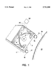
- FIG. 1 is a side elevational view in section of an ultraviolet emitter according to the present invention.
- the illustrated embodiment shows a UV emitter in a printing press for sheets of paper.
- An elongated high pressure gas discharge lamp serves as the radiation source 3.
- the radiation source for example a mercury vapor lamp, is arranged in a housing 1.
- Radiation source 3 is partially surrounded longitudinally by a semi-cylindrical reflector 5, which is covered with reflective metal on its interior surface. Radiation source 3 is aligned approximately with the focal point of reflector 5.
- Reflector 5 is arranged with its open longitudinal side aligned with an opening 7 in housing 1.
- the emissions from radiation source 3 can be emitted directly or through reflection on reflector 5 out of opening 7.
- reflector 5 On its side opposite or remote from opening 7, reflector 5 has a clearance 9. Clearance 9 allows the passage of air, through which an air current can pass, to cool radiation source 3.
- Opening 7 is required to be of rectangular shape to correspond with the elongated shape of radiation source 3.
- a first pipe 11 is arranged along one edge of opening 7 which corresponds to one longitudinal side of the rectangle.
- cold compressed air can be passed through conduits (not shown) into the first pipe.
- First pipe 11 is provided with a longitudinal air outlet 13, aligned with and directed toward the opposite edge of opening 7, to pass an air current over opening 7.
- air outlet 13 comprises a plurality of apertures arranged in series one after the other with identical spacing between them.
- a second pipe 15 is provided on housing 11 on the side of opening 7 opposite first pipe 11. Similar to first pipe 13, the second pipe can have compressed air flowing through it, and has an additional air outlet 17 extending in longitudinal direction of the second pipe for discharge of a flowing air current.
- a plurality of coolant passages are provided in the wall of housing 1.
- the coolant passages extend parallel to radiation source 3 for cooling housing 1.
- the UV emitter is arranged within a unit for surface treatment of a substrate 19.
- the UV emitter is within the printing press itself, with radiation source 3 extending parallel to the rotational axis of a roller 21.
- the treated substrate 19, in the form of a printed paper sheet, is conveyed over roller 21 past the UV emitter.
- Opening 7 in housing 1 is aligned with substrate 19.
- the additional air outlet 17 is configured on second pipe 15 such that the air current coming out of it impinges on substrate 19 approximately in the same area toward which opening 7 is directed. This air current cools substrate 19 and, at the same time, cools roller 21. If desired, the air current can also cool other parts of the printing press.
- a power supply unit 32 is provided before radiation source 3, in the current circuit 30 feeding the radiation source.
- the power supply unit can adjust the output of radiation source 3 by modifying the voltage, current or frequency supplied to the radiation source. Therefore, radiation source 3, in addition to a disconnected mode or state and an operational mode or state, also has two more modes or states, a top standby mode or state and a bottom standby mode or state. In the top standby mode the capacity of radiation source 3 is reduced to approximately 15 percent of normal radiation source output in the operational mode.
- the current intensity is set so that radiation source 3 in top standby mode continues to burn steadily. Thus, radiation source 3 can switch over in a few seconds from its top standby mode into its operational mode.
- the radiation source output is reduced to approximately 1 percent to 3 percent of the normal radiation source output.
- the actual required time for the changeover into operational mode from the bottom standby mode is increased.
- radiation source 3 can continue in emitter-saving operation over several hours in its bottom standby mode, without requiring disconnection of radiation source 3 because of heat build-up. This operation increases the life of radiation source 3 and saves electrical power. Relative to the power supply to perform this operation, the subject matter of U.S. patent application Ser. No. 08/640,631 of Wolfgang Heering and Peter Schwarz, filed concurrently herewith and entitled Method and Circuit Arrangement for Operating High Pressure Gas Discharge Lamp, is hereby incorporated by reference.
- radiation source 3 switches from its operational mode into top standby mode.
- the air current coming out of air outlet 13 of first pipe 11 acts as a curtain closing off opening 7 from the convection of warm air.
- the air current coming out of air outlet 17 of second pipe 15 cools substrate 19 and protects it from infrared radiation coming from radiation source 3.
- the air current coming through air clearance 9 cools radiation source 3.
- the power supply unit switches radiation source 3 from its top standby mode to its bottom standby mode.
- the power supply unit brings radiation source 3 back into an operational mode with normal output. According to this arrangement and method of operation of the printing press and the UV emitter, one or more of the described air currents can be deleted.
Abstract
Description
Claims (21)
Applications Claiming Priority (2)
| Application Number | Priority Date | Filing Date | Title |
|---|---|---|---|
| DE19516053A DE19516053C2 (en) | 1995-05-04 | 1995-05-04 | UV lamp |
| DE19516053.3 | 1995-05-04 |
Publications (1)
| Publication Number | Publication Date |
|---|---|
| US5751008A true US5751008A (en) | 1998-05-12 |
Family
ID=7760859
Family Applications (1)
| Application Number | Title | Priority Date | Filing Date |
|---|---|---|---|
| US08/640,630 Expired - Fee Related US5751008A (en) | 1995-05-04 | 1996-05-01 | Ultraviolet emitter |
Country Status (5)
| Country | Link |
|---|---|
| US (1) | US5751008A (en) |
| EP (1) | EP0741272B1 (en) |
| DE (2) | DE19516053C2 (en) |
| DK (1) | DK0741272T3 (en) |
| ES (1) | ES2121452T3 (en) |
Cited By (9)
| Publication number | Priority date | Publication date | Assignee | Title |
|---|---|---|---|---|
| US6035548A (en) * | 1996-04-04 | 2000-03-14 | Gew (Ec) Limited | UV dryer with improved reflector |
| US6201250B1 (en) | 1997-08-22 | 2001-03-13 | Richard C. Morlock | Sensor housing for UV curing chamber |
| US6621087B1 (en) | 1998-03-11 | 2003-09-16 | Arccure Technologies Gmbh | Cold light UV irradiation device |
| US6646278B1 (en) * | 1999-04-13 | 2003-11-11 | Ist Metz Gmbh | Irradiating device |
| US6655040B2 (en) | 2002-01-04 | 2003-12-02 | The Diagnostics Group, Inc. | Combination ultraviolet curing and infrared drying system |
| EP1279498A3 (en) * | 2001-07-26 | 2005-06-15 | Platsch GmbH & Co. KG | Dryer for printed products |
| JP2014210430A (en) * | 2013-04-04 | 2014-11-13 | 株式会社東通研 | Ultraviolet ray radiation device |
| US9939706B2 (en) | 2013-03-26 | 2018-04-10 | Clearink Displays, Inc. | Displaced porous electrode for frustrating TIR and returning light through exit pupil |
| JP2021509465A (en) * | 2018-04-20 | 2021-03-25 | ケーニッヒ ウント バウアー アー・ゲーKoenig & Bauer AG | A processing machine equipped with a radiant dryer and how to operate this dryer |
Families Citing this family (8)
| Publication number | Priority date | Publication date | Assignee | Title |
|---|---|---|---|---|
| DE19651977C2 (en) * | 1996-12-13 | 2001-03-01 | Michael Bisges | UV irradiation device |
| DE19807643C2 (en) * | 1998-02-23 | 2000-01-05 | Industrieservis Ges Fuer Innov | Method and device for drying a material to be dried on the surface of a rapidly conveyed carrier material, in particular for drying printing inks |
| DE19945074B4 (en) * | 1999-09-21 | 2007-01-18 | Printconcept Gmbh | Drying device for coated substrates |
| DE19945073C2 (en) * | 1999-09-21 | 2003-05-22 | Printconcept Gmbh | Drying device for coated substrates |
| DE102006053198B4 (en) * | 2006-11-09 | 2016-06-30 | Deutsche Mechatronics Gmbh | drying plant |
| DE102009015195A1 (en) | 2009-03-31 | 2010-10-07 | Matthias Koch | Radiation dryer i.e. UV-dryer, for drying and/or hardening e.g. lacquer layer, during manufacture of furniture, has holder movable along support rail, where radiator is varied in inclination angle in vertical orientation |
| DE102013217659A1 (en) * | 2013-09-04 | 2015-03-05 | Krones Ag | Container treatment machine for printing on containers |
| DE102018206152A1 (en) * | 2018-04-20 | 2019-10-24 | Koenig & Bauer Ag | Drying device for a printing material processing machine and method for operating a drying device |
Citations (10)
| Publication number | Priority date | Publication date | Assignee | Title |
|---|---|---|---|---|
| FR2370071A1 (en) * | 1976-11-05 | 1978-06-02 | Union Carbide Corp | PROCESS AND APPARATUS FOR CURING COATINGS BY LIGHT RAYS |
| FR2403529A1 (en) * | 1977-09-19 | 1979-04-13 | Pray Robert | INFRARED RAY DRYING APPARATUS, ESPECIALLY FOR PRINTED STRIPS |
| DE8318696U1 (en) * | 1983-06-28 | 1983-11-24 | Endlich, Wilhelm, 8000 München | DEVICE FOR IRRADIATING A SURFACE WITH UV-A LIGHT |
| US4434562A (en) * | 1981-09-02 | 1984-03-06 | American Screen Printing Equipment Company | Curing apparatus and method |
| DE3509939A1 (en) * | 1985-03-19 | 1986-09-25 | Rudolf Dipl.-Ing. 6360 Friedberg Weiner | Irradiation device |
| DE3744799A1 (en) * | 1986-02-06 | 1989-06-22 | Itronic Process Ab | Arrangement for a process installation for the heat treatment of web-like products |
| EP0416868A1 (en) * | 1989-09-08 | 1991-03-13 | W.R. Grace & Co.-Conn. | Reflector assembly for heating a substrate |
| WO1991012897A1 (en) * | 1990-02-28 | 1991-09-05 | Aetek International, Inc. | Ultraviolet light curing apparatus and process |
| GB2258296A (en) * | 1991-07-25 | 1993-02-03 | G E W | U.v. dryers |
| US5440137A (en) * | 1994-09-06 | 1995-08-08 | Fusion Systems Corporation | Screw mechanism for radiation-curing lamp having an adjustable irradiation area |
-
1995
- 1995-05-04 DE DE19516053A patent/DE19516053C2/en not_active Expired - Fee Related
-
1996
- 1996-04-25 ES ES96106499T patent/ES2121452T3/en not_active Expired - Lifetime
- 1996-04-25 DE DE59600559T patent/DE59600559D1/en not_active Expired - Fee Related
- 1996-04-25 DK DK96106499T patent/DK0741272T3/en active
- 1996-04-25 EP EP96106499A patent/EP0741272B1/en not_active Expired - Lifetime
- 1996-05-01 US US08/640,630 patent/US5751008A/en not_active Expired - Fee Related
Patent Citations (11)
| Publication number | Priority date | Publication date | Assignee | Title |
|---|---|---|---|---|
| FR2370071A1 (en) * | 1976-11-05 | 1978-06-02 | Union Carbide Corp | PROCESS AND APPARATUS FOR CURING COATINGS BY LIGHT RAYS |
| FR2403529A1 (en) * | 1977-09-19 | 1979-04-13 | Pray Robert | INFRARED RAY DRYING APPARATUS, ESPECIALLY FOR PRINTED STRIPS |
| US4434562A (en) * | 1981-09-02 | 1984-03-06 | American Screen Printing Equipment Company | Curing apparatus and method |
| DE8318696U1 (en) * | 1983-06-28 | 1983-11-24 | Endlich, Wilhelm, 8000 München | DEVICE FOR IRRADIATING A SURFACE WITH UV-A LIGHT |
| DE3509939A1 (en) * | 1985-03-19 | 1986-09-25 | Rudolf Dipl.-Ing. 6360 Friedberg Weiner | Irradiation device |
| DE3744799A1 (en) * | 1986-02-06 | 1989-06-22 | Itronic Process Ab | Arrangement for a process installation for the heat treatment of web-like products |
| EP0416868A1 (en) * | 1989-09-08 | 1991-03-13 | W.R. Grace & Co.-Conn. | Reflector assembly for heating a substrate |
| WO1991012897A1 (en) * | 1990-02-28 | 1991-09-05 | Aetek International, Inc. | Ultraviolet light curing apparatus and process |
| GB2258296A (en) * | 1991-07-25 | 1993-02-03 | G E W | U.v. dryers |
| US5343629A (en) * | 1991-07-25 | 1994-09-06 | G.E.W. (Ec) Limited | UV dryers |
| US5440137A (en) * | 1994-09-06 | 1995-08-08 | Fusion Systems Corporation | Screw mechanism for radiation-curing lamp having an adjustable irradiation area |
Cited By (10)
| Publication number | Priority date | Publication date | Assignee | Title |
|---|---|---|---|---|
| US6035548A (en) * | 1996-04-04 | 2000-03-14 | Gew (Ec) Limited | UV dryer with improved reflector |
| US6201250B1 (en) | 1997-08-22 | 2001-03-13 | Richard C. Morlock | Sensor housing for UV curing chamber |
| US6621087B1 (en) | 1998-03-11 | 2003-09-16 | Arccure Technologies Gmbh | Cold light UV irradiation device |
| US6646278B1 (en) * | 1999-04-13 | 2003-11-11 | Ist Metz Gmbh | Irradiating device |
| EP1279498A3 (en) * | 2001-07-26 | 2005-06-15 | Platsch GmbH & Co. KG | Dryer for printed products |
| US6655040B2 (en) | 2002-01-04 | 2003-12-02 | The Diagnostics Group, Inc. | Combination ultraviolet curing and infrared drying system |
| US9939706B2 (en) | 2013-03-26 | 2018-04-10 | Clearink Displays, Inc. | Displaced porous electrode for frustrating TIR and returning light through exit pupil |
| JP2014210430A (en) * | 2013-04-04 | 2014-11-13 | 株式会社東通研 | Ultraviolet ray radiation device |
| JP2021509465A (en) * | 2018-04-20 | 2021-03-25 | ケーニッヒ ウント バウアー アー・ゲーKoenig & Bauer AG | A processing machine equipped with a radiant dryer and how to operate this dryer |
| US11046070B2 (en) | 2018-04-20 | 2021-06-29 | Koenig & Bauer Ag | Processing machine comprising a radiation dryer and method for operating said dryer |
Also Published As
| Publication number | Publication date |
|---|---|
| EP0741272A3 (en) | 1997-03-12 |
| EP0741272B1 (en) | 1998-09-16 |
| DE59600559D1 (en) | 1998-10-22 |
| EP0741272A2 (en) | 1996-11-06 |
| DE19516053A1 (en) | 1996-11-14 |
| ES2121452T3 (en) | 1998-11-16 |
| DE19516053C2 (en) | 2000-08-24 |
| DK0741272T3 (en) | 1999-06-14 |
Similar Documents
| Publication | Publication Date | Title |
|---|---|---|
| US5751008A (en) | Ultraviolet emitter | |
| US7077547B2 (en) | Shuttered lamp assembly and method of cooling the lamp assembly | |
| US20040156191A1 (en) | Ground-embedded air cooled lighting device, in particular floodlight or sealed lamp | |
| US7731379B2 (en) | Hand held, high power UV lamp | |
| CA2189932A1 (en) | Welding Power Supply Housing | |
| JPH0353742B2 (en) | ||
| US5655312A (en) | UV curing/drying apparatus with interlock | |
| US8410410B2 (en) | Ultraviolet lamp system with cooling air control | |
| US20090040765A1 (en) | Lamp assembly comprising a high-pressure gas discharge lamp | |
| DE59809933D1 (en) | GAS DISCHARGE LAMP WITH SEPARATELY OPERABLE ELECTRODE GROUPS | |
| EP1243164B1 (en) | Built-in microwave oven | |
| AU1715097A (en) | Yankee hood with integral air heating system | |
| AU2003302860A1 (en) | Lighting unit | |
| KR20000003800U (en) | Halogen lamp cooling structure of microwave oven | |
| CA2064255A1 (en) | High frequency heating apparatus utilizing an inverter power supply | |
| US20020060529A1 (en) | Ultraviolet lamp power supply and method for operating at high power/reduced cooling using cycling | |
| JP2004518246A5 (en) | ||
| US5740313A (en) | Light beam heating apparatus | |
| US6784619B2 (en) | Electrodeless lighting system | |
| KR20030058020A (en) | Near infrared ray drying module, drying system having the same and method of controlling the same | |
| JPH06215616A (en) | Cooling of ultraviolet lamp | |
| JPWO2006080442A1 (en) | Irradiation apparatus and inkjet recording apparatus | |
| KR200165772Y1 (en) | High voltage transformer fixing apparatus | |
| EP1014002A3 (en) | Range, particularly electric range | |
| JPH03238041A (en) | Ultraviolet-ray irradiation apparatus |
Legal Events
| Date | Code | Title | Description |
|---|---|---|---|
| AS | Assignment |
Owner name: IST STRAHLENTECHNIK META GMBH, GERMANY Free format text: ASSIGNMENT OF ASSIGNORS INTEREST;ASSIGNORS:JUNG, JOACHIM;SCHWARZ, BERND;REEL/FRAME:007973/0298 Effective date: 19960424 |
|
| AS | Assignment |
Owner name: IST STRAHLENTECHNIK METZ GMBH, GERMANY Free format text: CORRECTIVE ASSIGNMENT TO CORRECT ASSIGNEE'S NAME. AN ASSIGNMENT WAS PREVIOUSLY RECORDED AT REEL 7973, FRAME 0298;ASSIGNORS:JUNG, JOACHIM;SCHWARZ, BERND;REEL/FRAME:008218/0327 Effective date: 19960424 |
|
| AS | Assignment |
Owner name: IST METZ GMBH, GERMANY Free format text: CHANGE OF NAME;ASSIGNOR:IST STRAHLENTECHNIK METZ GMBH;REEL/FRAME:009912/0266 Effective date: 19990113 |
|
| FPAY | Fee payment |
Year of fee payment: 4 |
|
| FPAY | Fee payment |
Year of fee payment: 8 |
|
| REMI | Maintenance fee reminder mailed | ||
| LAPS | Lapse for failure to pay maintenance fees | ||
| STCH | Information on status: patent discontinuation |
Free format text: PATENT EXPIRED DUE TO NONPAYMENT OF MAINTENANCE FEES UNDER 37 CFR 1.362 |
|
| FP | Lapsed due to failure to pay maintenance fee |
Effective date: 20100512 |