US5749871A - Method and apparatus for modifications of visual acuity by thermal means - Google Patents
Method and apparatus for modifications of visual acuity by thermal means Download PDFInfo
- Publication number
- US5749871A US5749871A US08/287,657 US28765794A US5749871A US 5749871 A US5749871 A US 5749871A US 28765794 A US28765794 A US 28765794A US 5749871 A US5749871 A US 5749871A
- Authority
- US
- United States
- Prior art keywords
- electrode
- probe
- cornea
- power
- eye
- Prior art date
- Legal status (The legal status is an assumption and is not a legal conclusion. Google has not performed a legal analysis and makes no representation as to the accuracy of the status listed.)
- Expired - Fee Related
Links
Images


Classifications
-
- A—HUMAN NECESSITIES
- A61—MEDICAL OR VETERINARY SCIENCE; HYGIENE
- A61F—FILTERS IMPLANTABLE INTO BLOOD VESSELS; PROSTHESES; DEVICES PROVIDING PATENCY TO, OR PREVENTING COLLAPSING OF, TUBULAR STRUCTURES OF THE BODY, e.g. STENTS; ORTHOPAEDIC, NURSING OR CONTRACEPTIVE DEVICES; FOMENTATION; TREATMENT OR PROTECTION OF EYES OR EARS; BANDAGES, DRESSINGS OR ABSORBENT PADS; FIRST-AID KITS
- A61F9/00—Methods or devices for treatment of the eyes; Devices for putting-in contact lenses; Devices to correct squinting; Apparatus to guide the blind; Protective devices for the eyes, carried on the body or in the hand
- A61F9/007—Methods or devices for eye surgery
- A61F9/008—Methods or devices for eye surgery using laser
-
- A—HUMAN NECESSITIES
- A61—MEDICAL OR VETERINARY SCIENCE; HYGIENE
- A61B—DIAGNOSIS; SURGERY; IDENTIFICATION
- A61B18/00—Surgical instruments, devices or methods for transferring non-mechanical forms of energy to or from the body
- A61B18/04—Surgical instruments, devices or methods for transferring non-mechanical forms of energy to or from the body by heating
- A61B18/12—Surgical instruments, devices or methods for transferring non-mechanical forms of energy to or from the body by heating by passing a current through the tissue to be heated, e.g. high-frequency current
- A61B18/14—Probes or electrodes therefor
-
- A—HUMAN NECESSITIES
- A61—MEDICAL OR VETERINARY SCIENCE; HYGIENE
- A61F—FILTERS IMPLANTABLE INTO BLOOD VESSELS; PROSTHESES; DEVICES PROVIDING PATENCY TO, OR PREVENTING COLLAPSING OF, TUBULAR STRUCTURES OF THE BODY, e.g. STENTS; ORTHOPAEDIC, NURSING OR CONTRACEPTIVE DEVICES; FOMENTATION; TREATMENT OR PROTECTION OF EYES OR EARS; BANDAGES, DRESSINGS OR ABSORBENT PADS; FIRST-AID KITS
- A61F9/00—Methods or devices for treatment of the eyes; Devices for putting-in contact lenses; Devices to correct squinting; Apparatus to guide the blind; Protective devices for the eyes, carried on the body or in the hand
- A61F9/007—Methods or devices for eye surgery
- A61F9/013—Instruments for compensation of ocular refraction ; Instruments for use in cornea removal, for reshaping or performing incisions in the cornea
- A61F9/0133—Knives or scalpels specially adapted therefor
-
- A—HUMAN NECESSITIES
- A61—MEDICAL OR VETERINARY SCIENCE; HYGIENE
- A61B—DIAGNOSIS; SURGERY; IDENTIFICATION
- A61B18/00—Surgical instruments, devices or methods for transferring non-mechanical forms of energy to or from the body
- A61B18/18—Surgical instruments, devices or methods for transferring non-mechanical forms of energy to or from the body by applying electromagnetic radiation, e.g. microwaves
- A61B18/1815—Surgical instruments, devices or methods for transferring non-mechanical forms of energy to or from the body by applying electromagnetic radiation, e.g. microwaves using microwaves
-
- A—HUMAN NECESSITIES
- A61—MEDICAL OR VETERINARY SCIENCE; HYGIENE
- A61B—DIAGNOSIS; SURGERY; IDENTIFICATION
- A61B18/00—Surgical instruments, devices or methods for transferring non-mechanical forms of energy to or from the body
- A61B2018/00053—Mechanical features of the instrument of device
- A61B2018/00172—Connectors and adapters therefor
- A61B2018/00178—Electrical connectors
-
- A—HUMAN NECESSITIES
- A61—MEDICAL OR VETERINARY SCIENCE; HYGIENE
- A61B—DIAGNOSIS; SURGERY; IDENTIFICATION
- A61B18/00—Surgical instruments, devices or methods for transferring non-mechanical forms of energy to or from the body
- A61B2018/00636—Sensing and controlling the application of energy
- A61B2018/00696—Controlled or regulated parameters
- A61B2018/00761—Duration
-
- A—HUMAN NECESSITIES
- A61—MEDICAL OR VETERINARY SCIENCE; HYGIENE
- A61B—DIAGNOSIS; SURGERY; IDENTIFICATION
- A61B18/00—Surgical instruments, devices or methods for transferring non-mechanical forms of energy to or from the body
- A61B2018/00636—Sensing and controlling the application of energy
- A61B2018/00773—Sensed parameters
- A61B2018/00886—Duration
-
- A—HUMAN NECESSITIES
- A61—MEDICAL OR VETERINARY SCIENCE; HYGIENE
- A61B—DIAGNOSIS; SURGERY; IDENTIFICATION
- A61B18/00—Surgical instruments, devices or methods for transferring non-mechanical forms of energy to or from the body
- A61B2018/00988—Means for storing information, e.g. calibration constants, or for preventing excessive use, e.g. usage, service life counter
-
- A—HUMAN NECESSITIES
- A61—MEDICAL OR VETERINARY SCIENCE; HYGIENE
- A61B—DIAGNOSIS; SURGERY; IDENTIFICATION
- A61B18/00—Surgical instruments, devices or methods for transferring non-mechanical forms of energy to or from the body
- A61B18/04—Surgical instruments, devices or methods for transferring non-mechanical forms of energy to or from the body by heating
- A61B18/12—Surgical instruments, devices or methods for transferring non-mechanical forms of energy to or from the body by heating by passing a current through the tissue to be heated, e.g. high-frequency current
- A61B18/14—Probes or electrodes therefor
- A61B2018/1405—Electrodes having a specific shape
- A61B2018/1425—Needle
- A61B2018/143—Needle multiple needles
-
- A—HUMAN NECESSITIES
- A61—MEDICAL OR VETERINARY SCIENCE; HYGIENE
- A61B—DIAGNOSIS; SURGERY; IDENTIFICATION
- A61B18/00—Surgical instruments, devices or methods for transferring non-mechanical forms of energy to or from the body
- A61B18/04—Surgical instruments, devices or methods for transferring non-mechanical forms of energy to or from the body by heating
- A61B18/12—Surgical instruments, devices or methods for transferring non-mechanical forms of energy to or from the body by heating by passing a current through the tissue to be heated, e.g. high-frequency current
- A61B18/14—Probes or electrodes therefor
- A61B2018/1475—Electrodes retractable in or deployable from a housing
-
- A—HUMAN NECESSITIES
- A61—MEDICAL OR VETERINARY SCIENCE; HYGIENE
- A61B—DIAGNOSIS; SURGERY; IDENTIFICATION
- A61B90/00—Instruments, implements or accessories specially adapted for surgery or diagnosis and not covered by any of the groups A61B1/00 - A61B50/00, e.g. for luxation treatment or for protecting wound edges
- A61B90/08—Accessories or related features not otherwise provided for
- A61B2090/0803—Counting the number of times an instrument is used
-
- A—HUMAN NECESSITIES
- A61—MEDICAL OR VETERINARY SCIENCE; HYGIENE
- A61F—FILTERS IMPLANTABLE INTO BLOOD VESSELS; PROSTHESES; DEVICES PROVIDING PATENCY TO, OR PREVENTING COLLAPSING OF, TUBULAR STRUCTURES OF THE BODY, e.g. STENTS; ORTHOPAEDIC, NURSING OR CONTRACEPTIVE DEVICES; FOMENTATION; TREATMENT OR PROTECTION OF EYES OR EARS; BANDAGES, DRESSINGS OR ABSORBENT PADS; FIRST-AID KITS
- A61F9/00—Methods or devices for treatment of the eyes; Devices for putting-in contact lenses; Devices to correct squinting; Apparatus to guide the blind; Protective devices for the eyes, carried on the body or in the hand
- A61F9/007—Methods or devices for eye surgery
- A61F9/008—Methods or devices for eye surgery using laser
- A61F2009/00853—Laser thermal keratoplasty or radial keratotomy
-
- A—HUMAN NECESSITIES
- A61—MEDICAL OR VETERINARY SCIENCE; HYGIENE
- A61F—FILTERS IMPLANTABLE INTO BLOOD VESSELS; PROSTHESES; DEVICES PROVIDING PATENCY TO, OR PREVENTING COLLAPSING OF, TUBULAR STRUCTURES OF THE BODY, e.g. STENTS; ORTHOPAEDIC, NURSING OR CONTRACEPTIVE DEVICES; FOMENTATION; TREATMENT OR PROTECTION OF EYES OR EARS; BANDAGES, DRESSINGS OR ABSORBENT PADS; FIRST-AID KITS
- A61F9/00—Methods or devices for treatment of the eyes; Devices for putting-in contact lenses; Devices to correct squinting; Apparatus to guide the blind; Protective devices for the eyes, carried on the body or in the hand
- A61F9/007—Methods or devices for eye surgery
- A61F9/008—Methods or devices for eye surgery using laser
- A61F2009/00861—Methods or devices for eye surgery using laser adapted for treatment at a particular location
- A61F2009/00872—Cornea
-
- A—HUMAN NECESSITIES
- A61—MEDICAL OR VETERINARY SCIENCE; HYGIENE
- A61F—FILTERS IMPLANTABLE INTO BLOOD VESSELS; PROSTHESES; DEVICES PROVIDING PATENCY TO, OR PREVENTING COLLAPSING OF, TUBULAR STRUCTURES OF THE BODY, e.g. STENTS; ORTHOPAEDIC, NURSING OR CONTRACEPTIVE DEVICES; FOMENTATION; TREATMENT OR PROTECTION OF EYES OR EARS; BANDAGES, DRESSINGS OR ABSORBENT PADS; FIRST-AID KITS
- A61F9/00—Methods or devices for treatment of the eyes; Devices for putting-in contact lenses; Devices to correct squinting; Apparatus to guide the blind; Protective devices for the eyes, carried on the body or in the hand
- A61F9/007—Methods or devices for eye surgery
- A61F9/0079—Methods or devices for eye surgery using non-laser electromagnetic radiation, e.g. non-coherent light or microwaves
Definitions
- the present invention relates to a thermokeratoplasty probe that is placed into direct contact with the outer surface of the cornea.
- myopic conditions can be corrected by cutting a number of small incisions in the corneal membrane.
- the incisions allow the corneal membrane to relax and increase the radius of the cornea.
- the incisions are typically created with either a laser or a precision knife.
- the procedure for creating incisions to correct myopic defects is commonly referred to as radial keratotomy and is well known in the art.
- radial keratotomy are only effective in correcting myopia. Radial keratotomy cannot be used to correct an eye condition such as hyperopia. Additionally, keratotomy has limited use in reducing or correcting an astigmatism.
- the cornea of a patient with hyperopia is relatively flat (large spherical radius). A flat cornea creates a lens system which does not correctly focus the viewed image onto the retina of the eye. Hyperopia can be corrected by reshaping the eye to decrease the spherical radius of the cornea. It has been found that hyperopia can be corrected by heating and denaturing local regions of the cornea. The denatured tissue contracts and changes the shape of the cornea and corrects the optical characteristics of the eye. The procedure of heating the corneal membrane to correct a patient's vision is commonly referred to as thermokeratoplasty.
- thermokeratoplastic techniques which utilize a laser to heat the cornea.
- the energy of the laser generates localized heat within the corneal stroma through photonic absorption.
- the heated areas of the stroma then shrink to change the shape of the eye.
- laser thermokeratoplastic techniques non-uniformly shrink the stroma without shrinking the Bowmans layer. Shrinking the stroma without a corresponding shrinkage of the Bowmans layer, creates a mechanical strain in the cornea. The mechanical strain may produce an undesirable reshaping of the cornea and probable regression of the visual acuity correction as the corneal lesion heals. Laser techniques may also perforate Bowmans layer and leave a leucoma within the visual field of the eye.
- the electrode is located within a housing that spaces the tip of the electrode from the surface of the eye.
- An isotropic saline solution is irrigated through the electrode and aspirated through a channel formed between the outer surface of the electrode and the inner surface of the sleeve.
- the saline solution provides an electrically conductive medium between the electrode and the corneal membrane.
- the current from the electrode heats the outer layers of the cornea. Heating the outer eye tissue causes the cornea to shrink into a new radial shape.
- the saline solution also functions as a coolant which cools the outer epithelium layer.
- the saline solution of the Doss device spreads the current of the electrode over a relatively large area of the cornea. Consequently, thermokeratoplasty techniques using the Doss device are limited to reshaped corneas with relatively large and undesirable denatured areas within the visual axis of the eye.
- the electrode device of the Doss system is also relatively complex and cumbersome to use.
- thermokeratoplasty technique for correcting hyperopia. Feldman inserted a probe into four different locations of the cornea. The probe was heated to 600° C. and was inserted into the cornea for 0.3 seconds. Like the procedure discussed in the McDonnell article, the Feldman technique initially reduced hyperopia, but the patients had a significant regression within 9 months of the procedure. To date, there has been no published findings of a thermokeratoplasty technique that will predictably reshape and correct the vision of a cornea without a significant regression of the corneal correction.
- thermokeratoplasty technique which can predictably reshape and correct the vision of an eye without a significant regression of the visual acuity correction.
- Electrodes are subject to contamination, when RF electrical current is used for thermokeratoplasty.
- an electrolized layer or protein film may form on the surface of the electrodes.
- Such a film may vary the impedance of the electrodes and affect the performance of the instrument. Varying instrument performance may create inconsistent results. Therefore it would be desirable to provide a thermokeratoplastic probe that would have to be replaced by a new device after a predetermined number of uses.
- the present invention is a thermokeratoplasty system and method for locally heating and reshaping a cornea in a manner that produces a minimal regression of the corneal correction.
- the system includes a probe that is coupled to a power source which can provide a predetermined power, frequency and time duration that creates a thermal profile within the cornea which extends from the epithelium into the corneal stroma.
- the electrical return of the probe is a lid speculum which maintains the eye lids in an open position.
- the probe is placed into contact with the cornea and energy is transferred from the power source to the eye, through the lid speculum and back to the power source.
- the energy from the power supply is focused by a probe tip that locally heats and denatures the cornea, and causes a subsequent shrinkage of corneal tissue.
- a pattern of denatured areas can be created around the cornea to correct the vision of the eye. It has been found that power no greater than 1.2 watts, for a duration no greater than 1.0 seconds, will sufficiently induce corneal shrinkage without any significant regression of the visual acuity correction of the eye.
- the probe may have an electronic circuit which prevents usage of the probe after a predetermined number of procedures.
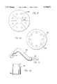
- FIG. 1 a perspective view of a thermokeratoplastic electrode system of the present invention
- FIG. 1a is a graph showing a waveform that is provided to the probe of the system
- FIG. 1b is a graph showing the amount of typical vision correction regression over time
- FIG. 1c is a representation of a nominal thermal profile within the cornea produced by the electrode system of the present invention.
- FIG. 2 is a top view of an electrode probe of the system
- FIG. 3 is a side view of the probe in FIG. 2;
- FIG. 4 is an enlarged view of the probe tip
- FIG. 5 is a side view showing the probe being used to treat an area of the corneal membrane
- FIG. 6 is a top view showing a pattern of denatured areas of the cornea
- FIG. 7 is a perspective view of an alternate embodiment of the probe.
- FIGS. 8a-b show a method for performing a procedure of the present invention
- FIG. 9 shows a pattern of incisions and denatured areas to correct for a myopic condition
- FIG. 10 shows another pattern of incisions and denatured areas to correct for hyperopic conditions
- FIG. 11 shows a preferred embodiment of the present invention
- FIG. 11a is an enlarged view of the tip of FIG. 11;
- FIG. 12 is a perspective view of a probe with the return electrode as a lid speculum that maintains the eye lid in an open position;
- FIG. 13 is a side view of an alternate probe tip embodiment
- FIG. 14 is a side view of an alternate probe tip embodiment
- FIG. 15 is a side view of an alternate probe tip embodiment
- FIG. 16 is a side view of an alternate probe tip embodiment
- FIG. 17 is a side view of an alternate probe tip embodiment
- FIG. 18 is a side view of an alternate probe embodiment
- FIG. 19 is a schematic of a circuit which limits the use of a probe beyond a predetermined useful life.
- FIG. 1 shows a thermokeratoplastic electrode system 10 of the present invention.
- the system 10 includes an electrode probe 12 coupled to a power supply unit 14.
- the power supply unit 14 contains a power supply which can deliver power to the probe 12.
- the probe 12 has a hand piece 16 and wires 18 that couple the probe electrodes to a connector 20 that plugs into a mating receptacle 22 located on the front panel 24 of the power unit.
- the hand piece 16 may be constructed from a non-conductive material and is approximately 0.5 inches in diameter and 5 inches long.
- the power supply 14 provides a predetermined amount of energy, through a controlled application of power for a predetermined time duration.
- the power supply 14 may have manual controls that allow the user to select treatment parameters such as the power and time duration.
- the power supply 14 can also be constructed to provide an automated operation.
- the supply 14 may have monitors and feedback systems for measuring tissue impedance, tissue temperature and other parameters, and adjust the output power of the supply to accomplish the desired results.
- the unit may also have a display that indicates the number of remaining uses available for the probe 12.
- the power supply provides a constant current source and voltage limiting to prevent arcing.
- the power unit 14 may have an upper voltage limit and/or upper power limit which terminates power to the probe when the output voltage or power of the unit exceeds a predetermined value.
- the power unit 14 may also contain monitor and alarm circuits which monitor the resistance or impedance of the load and provide an alarm when the resistance/impedance value exceeds and/or falls below predefined limits. The alarm may provide either an audio and/or visual indication to the user that the resistance/impedance value has exceeded the outer predefined limits.
- the unit may contain a ground fault indicator, and/or a tissue temperature monitor.
- the front panel of the power unit typically contains meters and displays that provide an indication of the power, frequency, etc., of the power delivered to the probe.
- the power unit 14 may deliver a power output in a frequency range of 5 KHz-50 MHz. In the preferred embodiment, power is provided to the probe at a frequency in the range of 500 KHz. The unit 14 is designed so that the power supplied to the probe 12 does not exceed 1.2 watts (W). The time duration of each application of power to a particular corneal location is typically between 0.1-1.0 seconds. The unit 14 is preferably set to deliver approximately 0.75 W of power for 0.75 seconds.
- FIG. 1a shows a typical voltage waveform that is applied by the unit 14. Each pulse of energy delivered by the unit 14 is a highly damped signal, typically having a crest factor (peak voltage/RMS voltage) greater than 10:1. Each power dissipation is provided at a repetitive rate. The repetitive rate may range between 4-12 KHz and is preferably set at 8 KHz.
- the system has a switch which controls the application of power to the probe 12.
- the power unit 14 also contains a timer circuit which allows power to be supplied to the probe 12 for a precise predetermined time interval.
- the timer may be a Dose timer or other similar conventional circuitry which terminates power to the probe after a predetermined time interval.
- the unit may also allow the user to apply power until the switch is released.
- the power supply may be a unit sold by Birtcher Medical Co. under the trademark HYFRECATOR PLUS, Model 7-797 which is modified to have voltage, waveform, time durations and power limits to comply with the above cited specifications.
- the power unit 14 may have a control member 26 to allow the user to select between a "uni-polar" or a "bi-polar” operation.
- the power supply 14 may be constructed to provide a single range of numerical settings, whereupon the appropriate output power, time duration and repetition rate are determined by the hardware and software of the unit.
- the front panel of the power unit may also have control members (not shown) that allow the surgeon to vary the power, frequency, timer interval, etc. of the unit.
- the return electrode (not shown) for a uni-polar probe may be coupled to the power unit through a connector located on the unit.
- the return electrode is preferably a cylindrical bar that is held by the patient, or an eye fixation electrode.
- FIG. 1b shows the amount of regression in the vision correction of the eye.
- the eyes were initially overcorrected to compensate for the known regression in the procedure. As shown in FIG. 1b, the regression became stabilized after approximately 60 days and completely stabilized after 180 days. The error in overcorrection was within +/-0.5 diopters.
- FIG. 1c shows nominal thermal profiles produced by the application of power to the cornea.
- the cornea includes an epithelium layer, a Bowmans membrane, a stroma, a Descemets membrane and a endothelium layer.
- the applicant provides the following discussion on the possible effects of the present method on the cornea of the eye.
- the cycle of dehydration and outward current flow continues until the resistance from the tip to the outer rim of the corneal surface, and the full thermal profile, is significantly high to prevent further current flow of a magnitude to further cause denaturing of the corneal tissue.
- the direct contact of the probe with the cornea along the specific power/time settings of the power source creates a thermal profile that denatures both the Bowman's membrane and the stroma.
- the denaturing of both the Bowman's membrane and the stroma in a circular pattern creates a linked belt type contracted annular ring. This annular ring will create a steepening of the cornea and sharpen the focus of the images on the retina.
- the surface of the eye is kept dry by applying either a dry swab to the cornea or blowing dry air or nitrogen across the surface of the eye.
- the design of the power source and the high electrical resistance of the denatured area provides a self limit on the amount of penetration and area of denaturing of the cornea.
- the cornea Once denatured, the cornea provides a high impedance to any subsequent application of power so that a relatively low amount of current flows through the denatured area. It has been found that the present procedure has a self limited denatured profile of approximately no greater than 75% of the depth of the stroma. This prevents the surgeon from denaturing the eye down to the decemets membrane and endothelium layer of the cornea.
- FIG. 1c shows nominal thermal profiles for diopter corrections of -1.5 d, -2.5-3.5 d and -4.0-6.0 d, respectively.
- a -1.5 diopter correction creates a denatured diameter of approximately 1 mm and a stroma penetration of approximately 30%.
- a -2.5-3.5 d correction creates a denatured diameter of approximately 1.13 mm and a stroma penetration of approximately 50%.
- a -4.0-6.0 d correction creates a denature diameter of approximately 1.25 mm and a stroma penetration of approximately 75%.
- FIGS. 2-5 show an embodiment of the probe 12.
- the probe 12 has a first electrode 30 and a second electrode 32. Although two electrodes are described and shown, it is to be understood that the probe may have either both electrodes (bipolar) or just the first electrode (unipolar). If a unipolar probe is used, a return electrode (indifferent electrode) is typically attached to, or held by, the patient to provide a "return" path for the current of the electrode.
- Both electrodes 30 and 32 extend from the hand piece 16 which contains a pair of internal insulated conductors 34 that are contact with the proximal end of the electrodes.
- the first electrode 30 has a tip 36 which extends from a first spring member 38 that is cantilevered from the hand piece 16.
- the electrode 30 is preferably constructed from a phosphor-bronze or stainless steel, wire or tube, that is 0.2-1.5 mm in diameter.
- the spring portion 38 of the first electrode 30 is preferably 50 millimeters (mm) long.
- the tip 36 has an included angle of between 15°-60°, 30° nominal, and a nose radius of approximately 50 microns.
- a majority of the electrode 30 is covered with an insulating material to prevent arcing, and to protect non-target tissue, the user and the patient.
- the relatively light spring force of the probe provides a sufficient electrode pressure without penetrating the cornea.
- the second electrode 32 includes a disk portion 40 which extends from a second spring member 42 that is also cantilevered from the hand piece 16.
- the disk portion 40 is spaced a predetermined distance from first electrode 30 and has an aperture 44 that is concentric with the tip 36.
- the disk portion 40 has an outer diameter of 5.5 mm and an aperture diameter of 3.0 mm.
- the disk 40 further has a concave bottom surface 46 that generally conforms to the shape of the cornea or sclera.
- the bottom surface 46 has a spherical radius of approximately 12.75 mm and a griping surface to assist in the fixation of the eye.
- the second electrode 32 provides a return path for the current from the first electrode 30.
- the surface area of the disk 40 is typically 20-500 times larger than the contact area of the tip 36.
- the second spring member 42 is constructed to have a spring constant that is less than one-half the stiffness of the first spring member 38, so that the second electrode 32 will have a greater deflection per unit force than the first electrode 30.
- the tip 36 and disk 40 are typically located at angles a' and a" which may range between 30°-180°, with the preferred embodiment being 45°.
- the probe 12 is pressed against the cornea to allow the second electrode 32 to deflect relative to the first electrode 30.
- the second electrode 32 is deflected until the tip 36 is in contact with the cornea.
- the probe could be constructed as two pieces, one piece being the first electrode, and the other piece being the second electrode which also stabilizes the eye against corneal movement.
- the probe has been described and shown denaturing a cornea, it is to be understood that the probes and methods of the present invention can be used to denature other tissues to correct for wrinkles, incontinence, etc.
- the probe could be used to shrink a sphincter to correct for incontinence.
- the technique would be basically the same with small closely spaced dots forming a tightening line, belt or cylinder.
- FIG. 6 shows a pattern of denatured areas 50 that have been found to correct hyperopic conditions.
- a circle of 8 or 16 denatured areas 50 are created about the center of the cornea, outside the visual axis portion 52 of the eye.
- the visual axis has a nominal diameter of approximately 5 millimeters. It has been found that 16 denatured areas provide the most corneal shrinkage and less post-op astigmatism effects from the procedure.
- the circle of denatured areas typically have a diameter between 6-8 mm, with a preferred diameter of approximately 7 mm. If the first circle does not correct the eye deficiency, the same pattern may be repeated, or another pattern of 8 denatured areas may be created within a circle having a diameter of approximately 6.0-6.5 mm either in line or overlapping.
- overcorrected hyperopic conditions may be reversed up to 80% by applying a steroid, such as cortisone, to the denatured areas within 4 days of post-op and continued for 2 weeks after the procedure.
- a steroid such as cortisone
- the exact diameter of the pattern may vary from patient to patient, it being understood that the denatured spots should preferably be formed in the non-visionary portion 52 of the eye. Although a circular pattern is shown, it is to be understood that the denatured areas may be located in any location and in any pattern.
- the present invention may be used to correct astigmatic conditions. For correcting astigmatic conditions, the denatured areas are typically created at the end of the astigmatic flat axis. The present invention may also be used to correct radial keratotomy procedures that have overcorrected for a myopic condition.
- the probe and power settings have been found to create denatured areas that do not reach the Decemets membrane. It has been found that denatured areas of the Bowmans layer in the field of vision may disturb the patients field of vision, particularly at night.
- the present invention leaves a scar that is almost imperceptible by slit lamp examination 6 months after the procedure. It has been found that the denatured areas generated by the present invention do not produce the star effect caused by the refraction of light through the slits created in a corrective procedure such as radial keratotomy.
- FIG. 7 shows an alternate embodiment of a probe 60 which has a plurality of first electrodes 62 coupled to a cage 64.
- the cage 64 includes a first ring 66 separated from a second ring 68 by a number of spacers 70.
- the cage 64 can be connected to a handle (not shown) which allows the surgeon to more easily utilize the probe 60.
- the first electrodes 62 extend through apertures 72 in the rings 66 and 68.
- the electrodes 62 can move relative to the cage 64 in the directions indicated by the arrows.
- the probe 60 has a plurality springs 74 located between the rings and seated on washers 76 mounted to the electrodes 62.
- the springs 74 bias the electrodes 62 into the positions shown in FIG. 7.
- the probe 60 includes 8 electrodes arranged in a circular pattern having a 7.0 millimeter diameter.
- the probe 60 is pressed onto the cornea so that the electrodes 62 move relative to the cage 64.
- the spring constant of the springs 74 is relatively low so that there is a minimal counterforce on the tissue.
- a current is supplied to the electrodes 62 through wires 78 attached thereto.
- the probe 60 is preferably used as a uni-polar device, wherein the current flows through the tissue and into a return electrode attached to or held by the patient.
- FIGS. 8a and 8b show a preferred method of correcting for hyperopic conditions using the electrode system of the present invention.
- refractive readings are initially taken of both eyes with, and then without, cycloplasia.
- procedure block 102 the interoccular pressure and cornea thickness at the center of the eye are taken with a tonometer and pacymeter, respectively. If the interoccular pressure is 20 mm Hg or greater, for I.O.P. reduction, 1 drop of a 0.5% solution marketed under the trademark "Betagan" is applied to the cornea twice a day for 2-3 months and then initial test are repeated. A topography reading of the eye is then taken to determine the shape of the cornea in procedural block 104.
- the patient is given a mild tranquilizer such as 5 mg of valium, and the surgeon administers drops, such as the drops marketed under the trademark "Madryacil", to dilate the pupil and freeze accommodation, in block 106.
- drops such as the drops marketed under the trademark "Madryacil”
- 2 drops of a topical cocaine commonly known as "Proparacaine” is administered to the eyes in block 108.
- an in line microscope light is directed to the cornea for marking purposes. Then the lighting may be directed in a lateral direction across the cornea. Laterally lighting the eye has been found to provide good visualization without irritating or photobleaching the retina.
- the surgeon marks 8 or 16 spots on the cornea, wherein the pattern has a preferred diameter of approximately 7 mm.
- the surgeon sets the power and duration setting of the power unit to the proper setting.
- the surgeon places the tip at one of the spot markings and depresses the foot switch of the system, so that power is supplied to the probe and transferred into the cornea. This process is repeated at all of the spot markings.
- the epithelium of the denatured areas are then removed with a spatula in block 116. If a diopter correction of -2.5-3.5 d, or -4.0-6.0 d is required the tip is again placed in contact with the spots and power is applied to the cornea to generate a deeper thermal profile in the stroma. The procedure is then checked with an autorefractor.
- the eyes are covered with a patch or dark glasses, and the patient is given medication, in block 118.
- the patient preferably takes an antibiotic such as a drug marketed under the trademark "Tobrex” every 2 hours for 48 hours, and then 3 times a day for 5 days.
- the patient also preferably takes an oral analgesic, such as a drug marketed under the trademark "Dolac”, 10 mg every 8 hours for 48 hours and a drug marketed under the trademark "Globaset” every 8 hours for 48 hours. If the patient has been overcorrected, the procedure can be reversed by waiting 3-4 days after the procedure and then administering to the eyes 1 drop of a steroid such as cortisone, 3 times a day for 1-2 weeks.
- a steroid such as cortisone
- FIG. 9 shows a pattern of denatured areas 130 combined with a pattern of incisions 132 that can correct myopic conditions.
- the incisions can be made with a knife or laser in accordance with conventional radial keratotomy procedures.
- the incisions are made from a 3.5 mm diameter to within 1 mm of the limbus at a depth of approximately 85% of the cornea.
- Denatured areas are then created between the incisions 132 using the procedure described above.
- the power unit is preferably set at 0.75 W of power and a time duration of 0.75 seconds.
- the slow heating of the cornea is important for minimizing regression, and as such 0.75 seconds has been found to be a preferable time duration to account for the patients fixation ability and the surgeons reaction time.
- the denatured areas pull the incisions to assist in the reshaping of the cornea. This procedure has been found to be effective for diopter corrections up to +10.0 d. Penetrating the cornea only 85% instead of conventional keratotomy incisions of 95% reduces the risk of puncturing the decemets membrane and the endothelium layer. This is to be distinguished from conventional radial keratotomy procedures which cannot typically correct for more than 3.5 diopters.
- the denatured pattern shown in FIG. 6 has been shown to correct up to 7.0 diopters.
- a circumferential pattern of incisions 134 may be created in addition to a pattern of denatured areas 136, to increase the correction up to 10.0 diopters.
- the incisions will weaken the eye and allow a more pronounced reshaping of the eye.
- the pattern of incisions may be created at either a 6 mm diameter or a 8 mm diameter.
- the incisions typically penetrate no greater than 75% of the cornea.
- the contractive forces of the denatured areas may create gaps in the incisions. It may be preferable to fill the gaps with collagen or other suitable material.
- FIG. 11 shows an alternate embodiment of a probe which has a single electrode 140.
- the electrode 140 has a tip 142 which is preferably 0.009 inches in diameter.
- the tip extends from a spring beam 144 that is bent so that the surgeon can place the tip onto the cornea over nose and brow without impairing the surgeon's vision.
- the spring beam 144 is preferably insulated and is 0.2-1.5 mm in diameter.
- the spring beam 144 extends from a base 146 that is inserted into the hand piece.
- the base 146 is preferably constructed from stainless steel and is 0.030-0.125 inches in diameter, with a preferred diameter of 0.060-0.095 inches.
- the end of the tip 142 is preferably flat and has a textured surface 148.
- the textured surface 148 slightly grips the cornea so that the tip does not move away from the marking when power is applied to the eye.
- the probe 200 has a return electrode lid speculum 202 that maintains the eye lid in an open position.
- the speculum 202 has a pair of cups 204 located at the end of wire 206.
- the cups 204 are placed under an eye lid and maintain the position of the lid during the procedure.
- Extending from the lid speculum 202 is a wire 208 that is typically plugged into the unit 14 "return" connector. It has been found that the procedure of the present invention will produce more consistent results when the probe 200 uses the lid speculum 202 as the return electrode.
- the impedance path between the probe 200 and the lid speculum 202 is relatively consistent because of the relatively short distance between the lid speculum 202 and the probe 200, and the wet interface between the cornea and the lid speculum 202.
- FIGS. 13-15 show alternate probe tip embodiments.
- the tips have steps that increase the current density at the corneal interface.
- the tips are preferably constructed from a stainless steel that is formed to the shapes shown.
- the tip 220 shown in FIG. 13 has a cylindrical step 222 that extends from a base 224.
- the step 222 terminates to a point, although it is to be understood that the end of the step 222 may have a flat surface.
- the base 224 has a diameter of 350 microns (um), and the step 222 has a diameter of 190 microns and a length of 210 microns.
- the tip 230 shown in FIG. 14, has a first step 232 extending from a base portion 234 and a second step 236 extending from the first step 232.
- the end of the second step 236 may be textured to improve the contact between the probe and the cornea.
- the first step 232 has a diameter of 263 microns and a length of 425 microns
- the second step 236 has a diameter of 160 microns and a length of 150 microns.
- the tip 240 shown in FIG. 15, has a first step 242 that extends from a base portion 244 and a second tapered step 246 that extends from the first step 242.
- the first step 242 has a diameter of 290 microns and a length of 950 microns.
- the second step 246 has a diameter of 150 microns, a length of 94 microns and a radius of 70 microns.
- FIGS. 16 and 17 show alternate probe tip embodiments which have an outer electrode concentric with an inner electrode.
- the electrodes are coupled to the unit so that the electrodes can provide current to the cornea either simultaneously or sequentially.
- the inner electrode will apply power with a greater current density that the outer electrode.
- the dual electrode probes allow the surgeon to create different thermal profiles, by varying the current densities, waveforms, etc. of the electrodes.
- the probe 250 shown in FIG. 16 has an inner electrode 252 that is concentric with an intermediate layer of insulative material 254 and an outer conductive layer 256.
- the inner electrode 252 may have a diameter of 125 microns and extend from the outer layers a length of 150 microns.
- the outer layer 256 may have diameter of 350 microns.
- the inner electrode 252 may be capable of being retracted into the insulative layer 254 so that the inner electrode 252 is flush with the outer electrode 256, or may be adjusted between flush and full extension, either manually or under servo control.
- FIG. 17 shows another alternate embodiment, wherein the probe 260 has an additional outer sleeve 262.
- the sleeve 262 has an internal passage 264 that supplies a fluid.
- the fluid may be a gas that stabilizes the current path to the cornea or a relatively high impedance solution (such as distilled water) which provides a coolant for the eye.
- FIG. 18 shows an economical detachable probe 270 embodiment.
- the probe tip 270 has a conductive wire 272 that is located within a plastic outer housing 274.
- the probe tip 270 has a flexible section 276 that extends from a body 278, preferably at a 45° angle.
- the tip 280 extends from the flexible section 276, preferably at a 90° angle.
- Extending from the opposite end of the handle 278 is a male connector 282.
- the connector 282 may have a conductive sleeve 284 that is inserted into the socket 286 of a female probe connector 288.
- the end of the wire 272 may be pressed between the inner surface of the sleeve 284 and the outer surface of the male connector 282 to provide an electrical interconnect between the tip end 280 and the female probe connector 288.
- the sleeve 284 may have a detent 290 to secure the probe tip 270 to the probe connector 288.
- the probe tip end 280 may have distal shape configurations similar to the tips shown in FIGS. 11, 13, 14, 15, 16, or 17.
- FIG. 19 shows a circuit 300 that will prevent the use of the probe tip beyond a predetermined useful life.
- the circuit 300 has a plurality of fuses 302 that are blown each time the probe is used for a procedure. The probe is rendered inoperative when all of the fuses 302 are blown.
- the circuit 200 typically has 10-30 fuses 302, so that the probe can only be used 10-30 times.
- the circuit 300 (not shown) is preferably located on a printed circuit board (not shown) mounted to the probe.
- the fuses 302 may be covered with a flash inhibitor such as silica sand to prevent fuse alloy splatter/spray when the fuses are blown.
- the fuses 302 are connected to drivers 304 that are coupled to a plurality of serial to parallel shift registers 306.
- the clock pin (CLK) pins and input pin D of the first shift register are connected to the unit 14.
- the unit 14 initially provides an input to the first shift register and then shifts the input through the registers 306 by providing a series of pulses on the clock pin CLK.
- An active output of a register 306 will enable the corresponding driver 304 and select the corresponding fuse 302.
- the unit 14 may clock the input through the shift registers 306 in accordance with an algorithm contained in hardware or software of the unit, wherein each clock signal corresponds to the end of a procedure.
- a clock signal may be generated, and a fuse blown, upon the occurrence of four shots that have a power greater than 0.16 W and a duration greater than 0.25 seconds.
- the circuit 300 may have a separate sample unit 308 that is coupled to the unit 14 and the fuses 302.
- the sample unit 308 may have an optical coupler 310 which isolates the unit 14 from power surges, etc. or may be any voltage or current threshold/comparator circuitry known in the art.
- the sample unit 308 may have a relay 312 that closes a switch when the fuses 302 are to be sampled.
- the sample circuit 308 samples the fuses 302 to determine how many fuses 302 are not blown.
- the number of remaining fuses 302, which correlate to the amount of procedures that can be performed with that particular probe, may be provided by a display on the unit 14. By way of example, after sampling the fuses, the unit 14 may display the number 6 providing an indication that 6 more procedures can be performed with the probe. A 0 on the display may provide an indication that the probe must be replaced.
- the unit 14 sets relay 312 to "sample” and clocks an input through the registers 306. If the fuse 302 is not blown when the corresponding driver 304 is enabled by the output of the register, the optical coupler 310 will be enabled. If the fuse 302 is blown the optical coupler 310 will not be enabled. The process of enabling a driver 304 and monitoring the output of optical coupler 310 is repeated for each fuse 302. The unit 14 counts the number of viable fuse links remaining to determine the remaining useful lifes of the probe.
Abstract
Description
              TABLE I
______________________________________
-d      DOTS/LOC  LOC      PWR (W)
                                  TIME (SEC)
______________________________________
1.5     1         8        0.66   .75
2.5     2         8        0.66   .75
3.5     2         8        0.83   .75
4.5     2         16       0.66   .75
6.0     2         16       0.83   .75
______________________________________
Claims (11)
Priority Applications (31)
| Application Number | Priority Date | Filing Date | Title |
|---|---|---|---|
| US08/287,657 US5749871A (en) | 1993-08-23 | 1994-08-09 | Method and apparatus for modifications of visual acuity by thermal means |
| ES94925975T ES2194872T3 (en) | 1993-08-23 | 1994-08-22 | SYSTEM FOR THE MODIFICATION OF VISUAL ACUTE BY THERMAL MEANS. |
| JP50770595A JP3282102B2 (en) | 1993-08-23 | 1994-08-22 | Change of visual acuity by thermal means |
| EP02019545A EP1262156B1 (en) | 1993-08-23 | 1994-08-22 | Modifications of visual acuity by thermal means |
| PL94313222A PL313222A1 (en) | 1993-08-23 | 1994-08-22 | Method of modifying visual acuity using technical means |
| DE69433767T DE69433767T2 (en) | 1993-08-23 | 1994-08-22 | Changes in visual acuity by thermal means |
| CA002169943A CA2169943C (en) | 1993-08-23 | 1994-08-22 | Modifications of visual acuity by thermal means |
| KR1019960700893A KR100337431B1 (en) | 1993-08-23 | 1994-08-22 | Control of vision by the thermal device |
| CNB941937569A CN1142747C (en) | 1993-08-23 | 1994-08-22 | Modification of visual acuity by thermal means |
| DE69432519T DE69432519T2 (en) | 1993-08-23 | 1994-08-22 | SYSTEM FOR CHANGING VISUALITY WITH THERMAL AGENTS |
| PCT/US1994/009443 WO1995005780A1 (en) | 1993-08-23 | 1994-08-22 | Modifications of visual acuity by thermal means |
| EP94925975A EP0715505B1 (en) | 1993-08-23 | 1994-08-22 | System for modification of visual acuity by thermal means |
| RU96107037/14A RU2187979C2 (en) | 1994-08-09 | 1994-08-22 | Method for making vision correction using heat treatment |
| BR9407569A BR9407569A (en) | 1993-08-23 | 1994-08-22 | Changes in visual acuity by means of a thermal device |
| AT02019545T ATE265834T1 (en) | 1993-08-23 | 1994-08-22 | CHANGES IN VISUAL ACUITY DUE TO THERMAL AGENTS |
| AU76011/94A AU691198B2 (en) | 1993-08-23 | 1994-08-22 | Modifications of visual acuity by thermal means |
| CNB031551815A CN1281194C (en) | 1993-08-23 | 1994-08-22 | Improvement of visual sensitivity by thermoelectric device |
| AT94925975T ATE237284T1 (en) | 1993-08-23 | 1994-08-22 | SYSTEM FOR CHANGING VISUAL ACUITY THROUGH THERMAL MEANS |
| ES02019545T ES2219614T3 (en) | 1993-08-23 | 1994-08-22 | MODIFICATIONS OF VISUAL ACUTE BY THERMAL MEDIA. |
| MXPA94006424A MXPA94006424A (en) | 1993-08-23 | 1994-08-23 | Method and apparatus for modifications of visual acuity by thermal means. |
| US08/488,829 US5634921A (en) | 1993-08-23 | 1995-06-08 | Method and apparatus for modifications of visual acuity by thermal means |
| NO960716A NO960716L (en) | 1993-08-23 | 1996-02-22 | Modifications of visual acuity by means of a heating device |
| US08/957,911 US6213997B1 (en) | 1993-08-23 | 1997-10-27 | Apparatus for modifications of visual acuity by thermal means |
| US09/819,561 US20020002369A1 (en) | 1993-08-23 | 2001-03-27 | Method and apparatus for modifying visual acuity by moving a focal point of energy within a cornea |
| JP2001313069A JP2002159524A (en) | 1993-08-23 | 2001-10-10 | Modification of visual acuity by thermal means |
| US10/301,113 US7018377B2 (en) | 1993-08-23 | 2002-11-20 | Method and apparatus for modifications of visual acuity by thermal means |
| US10/393,536 US20030181903A1 (en) | 1993-08-23 | 2003-03-20 | Method and apparatus for modifications of visual acuity by thermal means |
| US10/681,351 US6986770B2 (en) | 1993-08-23 | 2003-10-07 | Thermokeratoplasty system with a power supply that can determine a wet or dry cornea |
| US10/830,373 US20040199158A1 (en) | 1993-08-23 | 2004-04-21 | Method and apparatus for modifications of visual acuity by thermal means |
| US10/834,284 US20040204707A1 (en) | 1993-08-23 | 2004-04-27 | Method and apparatus for modifications of visual acuity by thermal means |
| JP2005195451A JP2005324055A (en) | 1993-08-23 | 2005-07-04 | Modifications of visual acuity by thermal means |
Applications Claiming Priority (3)
| Application Number | Priority Date | Filing Date | Title |
|---|---|---|---|
| US11129693A | 1993-08-23 | 1993-08-23 | |
| US17125593A | 1993-12-20 | 1993-12-20 | |
| US08/287,657 US5749871A (en) | 1993-08-23 | 1994-08-09 | Method and apparatus for modifications of visual acuity by thermal means |
Related Parent Applications (2)
| Application Number | Title | Priority Date | Filing Date |
|---|---|---|---|
| US17125593A Continuation-In-Part | 1993-08-23 | 1993-12-20 | |
| US17122593A Continuation-In-Part | 1993-08-23 | 1993-12-20 |
Related Child Applications (1)
| Application Number | Title | Priority Date | Filing Date |
|---|---|---|---|
| US08/957,911 Continuation-In-Part US6213997B1 (en) | 1993-08-23 | 1997-10-27 | Apparatus for modifications of visual acuity by thermal means |
Publications (1)
| Publication Number | Publication Date |
|---|---|
| US5749871A true US5749871A (en) | 1998-05-12 |
Family
ID=26808788
Family Applications (1)
| Application Number | Title | Priority Date | Filing Date |
|---|---|---|---|
| US08/287,657 Expired - Fee Related US5749871A (en) | 1993-08-23 | 1994-08-09 | Method and apparatus for modifications of visual acuity by thermal means |
Country Status (1)
| Country | Link |
|---|---|
| US (1) | US5749871A (en) |
Cited By (100)
| Publication number | Priority date | Publication date | Assignee | Title |
|---|---|---|---|---|
| WO1999045869A1 (en) | 1998-03-09 | 1999-09-16 | Ista Pharmaceuticals, Inc. | Use of corneal hardening agents in enzyme orthokeratology |
| US5957921A (en) * | 1996-11-07 | 1999-09-28 | Optex Ophthalmologics, Inc. | Devices and methods useable for forming small openings in the lens capsules of mammalian eyes |
| WO2000009027A1 (en) * | 1998-08-13 | 2000-02-24 | Keravision, Inc. | Corneal electrosurgical probe with a variable-height active site |
| US6036688A (en) * | 1998-06-17 | 2000-03-14 | Edwards; Stuart D. | Radio frequency refractive keratectomy apparatus and method |
| US6251106B1 (en) * | 1995-09-26 | 2001-06-26 | Sherwood Services Ag | Electrosurgical generator power control circuit and method |
| US20020002369A1 (en) * | 1993-08-23 | 2002-01-03 | Hood Larry L. | Method and apparatus for modifying visual acuity by moving a focal point of energy within a cornea |
| US6352535B1 (en) * | 1997-09-25 | 2002-03-05 | Nanoptics, Inc. | Method and a device for electro microsurgery in a physiological liquid environment |
| US6402748B1 (en) * | 1998-09-23 | 2002-06-11 | Sherwood Services Ag | Electrosurgical device having a dielectrical seal |
| WO2002098311A1 (en) * | 2001-06-01 | 2002-12-12 | Celon Ag Medical Instruments | Limiting the use frequency of electromedical products |
| US20030004500A1 (en) * | 1999-04-07 | 2003-01-02 | Visx, Inc. | Interface for laser eye surgery |
| US20030181903A1 (en) * | 1993-08-23 | 2003-09-25 | Hood Larry L. | Method and apparatus for modifications of visual acuity by thermal means |
| US6638274B2 (en) * | 1998-10-02 | 2003-10-28 | Olympus Optical Co., Ltd. | High-frequency coagulation apparatus |
| US6673069B1 (en) | 2000-03-30 | 2004-01-06 | Refractec, Inc. | Thermokeratoplasty system with a power supply that can determine a wet or dry cornea |
| US20040004510A1 (en) * | 2002-07-02 | 2004-01-08 | Infineon Technologies North America Corp. | Shift register for sequential fuse latch operation |
| US6723093B2 (en) | 2002-03-22 | 2004-04-20 | Refractec Inc. | Electrode assembly for a thermokeratoplasty system used to correct vision acuity |
| US20040088029A1 (en) * | 2001-03-30 | 2004-05-06 | Olympus Optical Co., Ltd. | High-frequency coagulation apparatus |
| US20040111086A1 (en) * | 2002-12-09 | 2004-06-10 | Trembly B. Stuart | Feedback control of thermokeratoplasty treatments |
| US20050113890A1 (en) * | 2003-11-25 | 2005-05-26 | Ritchie Paul G. | Energy delivery device with self-heat calibration |
| US20050113815A1 (en) * | 2003-11-26 | 2005-05-26 | Ritchie Paul G. | Medical treatment system with energy delivery device for limiting reuse |
| US20050135749A1 (en) * | 2003-12-19 | 2005-06-23 | Nield Scott A. | Optical fiber tip diffuser and method of making same |
| US20050135772A1 (en) * | 2003-12-19 | 2005-06-23 | Nield Scott A. | Optical fiber for a laser device having an improved tip diffuser and method of making same |
| US20050149006A1 (en) * | 2001-11-07 | 2005-07-07 | Peyman Gholam A. | Device and method for reshaping the cornea |
| US20050177149A1 (en) * | 2001-11-07 | 2005-08-11 | Peyman Gholam A. | Method and apparatus for reshaping the cornea by controlled thermal delivery |
| US20060064083A1 (en) * | 2004-09-17 | 2006-03-23 | Steve Khalaj | Multi-tip probe used for an ocular procedure |
| US7063695B2 (en) | 2003-12-19 | 2006-06-20 | Ethicon Endo-Surgery, Inc. | Optical fiber for a laser device having an improved diffuser slug and method of making same |
| US20060167422A1 (en) * | 2003-12-30 | 2006-07-27 | Mohsen Shahinpoor | Heat Shrink Scleral Band With Custom-Made Buckle For Retinal Detachment Surgery |
| US7147636B1 (en) | 2002-09-19 | 2006-12-12 | Minu, Llc | Method and apparatus for corneal shrinkage using a plurality of electrodes |
| US20070038211A1 (en) * | 2005-08-15 | 2007-02-15 | Yaldo Mazin K | Method and system for conductive keratoplasty |
| US20070038234A1 (en) * | 2005-08-15 | 2007-02-15 | Yaldo Mazin K | Instrumentation for conductive keratoplasty |
| US20070055227A1 (en) * | 2005-09-08 | 2007-03-08 | Refractec, Inc. | Probe used for an ocular procedure |
| US20070073286A1 (en) * | 2005-09-29 | 2007-03-29 | Dorin Panescu | Method and apparatus for an ocular procedure |
| US20070088415A1 (en) * | 2001-11-07 | 2007-04-19 | Minu Llc | Method of treating the eye using controlled heat delivery |
| US20070142828A1 (en) * | 2001-11-07 | 2007-06-21 | Minu, Llc | Method and system for altering the refractive properties of the eye |
| US20070149966A1 (en) * | 1995-11-22 | 2007-06-28 | Arthrocare Corporation | Electrosurgical Apparatus and Methods for Treatment and Removal of Tissue |
| US20070161976A1 (en) * | 2002-12-09 | 2007-07-12 | Trembly B S | Thermokeratoplasty systems |
| US20070282323A1 (en) * | 2006-05-30 | 2007-12-06 | Arthrocare Corporation | Hard tissue ablation system |
| US20080114428A1 (en) * | 2002-12-09 | 2008-05-15 | The Trustees Of Dartmouth | Thermal Treatment Systems With Acoustic Monitoring, And Associated Methods |
| US20090036883A1 (en) * | 2007-07-30 | 2009-02-05 | Robert Behnke | Electrosurgical systems and printed circuit boards for use therewith |
| US7632267B2 (en) * | 2005-07-06 | 2009-12-15 | Arthrocare Corporation | Fuse-electrode electrosurgical apparatus |
| US7648499B2 (en) | 2006-03-21 | 2010-01-19 | Covidien Ag | System and method for generating radio frequency energy |
| US7651492B2 (en) | 2006-04-24 | 2010-01-26 | Covidien Ag | Arc based adaptive control system for an electrosurgical unit |
| US7651493B2 (en) | 2006-03-03 | 2010-01-26 | Covidien Ag | System and method for controlling electrosurgical snares |
| US7678069B1 (en) | 1995-11-22 | 2010-03-16 | Arthrocare Corporation | System for electrosurgical tissue treatment in the presence of electrically conductive fluid |
| US7722601B2 (en) | 2003-05-01 | 2010-05-25 | Covidien Ag | Method and system for programming and controlling an electrosurgical generator system |
| US7731717B2 (en) | 2006-08-08 | 2010-06-08 | Covidien Ag | System and method for controlling RF output during tissue sealing |
| US7749217B2 (en) | 2002-05-06 | 2010-07-06 | Covidien Ag | Method and system for optically detecting blood and controlling a generator during electrosurgery |
| US7766693B2 (en) | 2003-11-20 | 2010-08-03 | Covidien Ag | Connector systems for electrosurgical generator |
| US7766905B2 (en) | 2004-02-12 | 2010-08-03 | Covidien Ag | Method and system for continuity testing of medical electrodes |
| US7780662B2 (en) | 2004-03-02 | 2010-08-24 | Covidien Ag | Vessel sealing system using capacitive RF dielectric heating |
| US7794457B2 (en) | 2006-09-28 | 2010-09-14 | Covidien Ag | Transformer for RF voltage sensing |
| US7824400B2 (en) | 2002-12-10 | 2010-11-02 | Covidien Ag | Circuit for controlling arc energy from an electrosurgical generator |
| US7834484B2 (en) | 2007-07-16 | 2010-11-16 | Tyco Healthcare Group Lp | Connection cable and method for activating a voltage-controlled generator |
| US7862560B2 (en) | 2007-03-23 | 2011-01-04 | Arthrocare Corporation | Ablation apparatus having reduced nerve stimulation and related methods |
| US20110037484A1 (en) * | 2009-08-12 | 2011-02-17 | Tyco Healthcare Group Lp | System and Method for Augmented Impedance Sensing |
| US7901400B2 (en) | 1998-10-23 | 2011-03-08 | Covidien Ag | Method and system for controlling output of RF medical generator |
| US7927328B2 (en) | 2006-01-24 | 2011-04-19 | Covidien Ag | System and method for closed loop monitoring of monopolar electrosurgical apparatus |
| US7947039B2 (en) | 2005-12-12 | 2011-05-24 | Covidien Ag | Laparoscopic apparatus for performing electrosurgical procedures |
| US7972328B2 (en) | 2006-01-24 | 2011-07-05 | Covidien Ag | System and method for tissue sealing |
| US8016824B2 (en) | 2002-07-25 | 2011-09-13 | Covidien Ag | Electrosurgical pencil with drag sensing capability |
| US8025660B2 (en) | 2004-10-13 | 2011-09-27 | Covidien Ag | Universal foot switch contact port |
| US8034049B2 (en) | 2006-08-08 | 2011-10-11 | Covidien Ag | System and method for measuring initial tissue impedance |
| US8096961B2 (en) | 2003-10-30 | 2012-01-17 | Covidien Ag | Switched resonant ultrasonic power amplifier system |
| US8105323B2 (en) | 1998-10-23 | 2012-01-31 | Covidien Ag | Method and system for controlling output of RF medical generator |
| US8104956B2 (en) | 2003-10-23 | 2012-01-31 | Covidien Ag | Thermocouple measurement circuit |
| US8147485B2 (en) | 2006-01-24 | 2012-04-03 | Covidien Ag | System and method for tissue sealing |
| USD658760S1 (en) | 2010-10-15 | 2012-05-01 | Arthrocare Corporation | Wound care electrosurgical wand |
| US8187262B2 (en) | 2006-01-24 | 2012-05-29 | Covidien Ag | Dual synchro-resonant electrosurgical apparatus with bi-directional magnetic coupling |
| US8192424B2 (en) | 2007-01-05 | 2012-06-05 | Arthrocare Corporation | Electrosurgical system with suction control apparatus, system and method |
| US8216220B2 (en) | 2007-09-07 | 2012-07-10 | Tyco Healthcare Group Lp | System and method for transmission of combined data stream |
| US8216223B2 (en) | 2006-01-24 | 2012-07-10 | Covidien Ag | System and method for tissue sealing |
| US8226639B2 (en) | 2008-06-10 | 2012-07-24 | Tyco Healthcare Group Lp | System and method for output control of electrosurgical generator |
| US8257350B2 (en) | 2009-06-17 | 2012-09-04 | Arthrocare Corporation | Method and system of an electrosurgical controller with wave-shaping |
| US8287528B2 (en) | 1998-10-23 | 2012-10-16 | Covidien Ag | Vessel sealing system |
| US8372067B2 (en) | 2009-12-09 | 2013-02-12 | Arthrocare Corporation | Electrosurgery irrigation primer systems and methods |
| US8460289B2 (en) | 2005-06-28 | 2013-06-11 | Covidien Ag | Electrode with rotatably deployable sheath |
| US8486061B2 (en) | 2009-01-12 | 2013-07-16 | Covidien Lp | Imaginary impedance process monitoring and intelligent shut-off |
| US8512332B2 (en) | 2007-09-21 | 2013-08-20 | Covidien Lp | Real-time arc control in electrosurgical generators |
| US8568405B2 (en) | 2010-10-15 | 2013-10-29 | Arthrocare Corporation | Electrosurgical wand and related method and system |
| US8574187B2 (en) | 2009-03-09 | 2013-11-05 | Arthrocare Corporation | System and method of an electrosurgical controller with output RF energy control |
| US8636685B2 (en) | 2006-01-06 | 2014-01-28 | Arthrocare Corporation | Electrosurgical method and system for treating foot ulcer |
| US8663214B2 (en) | 2006-01-24 | 2014-03-04 | Covidien Ag | Method and system for controlling an output of a radio-frequency medical generator having an impedance based control algorithm |
| US8685018B2 (en) | 2010-10-15 | 2014-04-01 | Arthrocare Corporation | Electrosurgical wand and related method and system |
| US8685016B2 (en) | 2006-01-24 | 2014-04-01 | Covidien Ag | System and method for tissue sealing |
| US8734438B2 (en) | 2005-10-21 | 2014-05-27 | Covidien Ag | Circuit and method for reducing stored energy in an electrosurgical generator |
| US8747399B2 (en) | 2010-04-06 | 2014-06-10 | Arthrocare Corporation | Method and system of reduction of low frequency muscle stimulation during electrosurgical procedures |
| US8753334B2 (en) | 2006-05-10 | 2014-06-17 | Covidien Ag | System and method for reducing leakage current in an electrosurgical generator |
| US8777941B2 (en) | 2007-05-10 | 2014-07-15 | Covidien Lp | Adjustable impedance electrosurgical electrodes |
| US8808161B2 (en) | 2003-10-23 | 2014-08-19 | Covidien Ag | Redundant temperature monitoring in electrosurgical systems for safety mitigation |
| US8876746B2 (en) | 2006-01-06 | 2014-11-04 | Arthrocare Corporation | Electrosurgical system and method for treating chronic wound tissue |
| US9131597B2 (en) | 2011-02-02 | 2015-09-08 | Arthrocare Corporation | Electrosurgical system and method for treating hard body tissue |
| US9186200B2 (en) | 2006-01-24 | 2015-11-17 | Covidien Ag | System and method for tissue sealing |
| US9358063B2 (en) | 2008-02-14 | 2016-06-07 | Arthrocare Corporation | Ablation performance indicator for electrosurgical devices |
| US9474564B2 (en) | 2005-03-31 | 2016-10-25 | Covidien Ag | Method and system for compensating for external impedance of an energy carrying component when controlling an electrosurgical generator |
| US9504607B2 (en) | 2010-05-07 | 2016-11-29 | Carl Zeiss Meditec Ag | Method and device for stabilizing the cornea |
| US9636165B2 (en) | 2013-07-29 | 2017-05-02 | Covidien Lp | Systems and methods for measuring tissue impedance through an electrosurgical cable |
| US9693818B2 (en) | 2013-03-07 | 2017-07-04 | Arthrocare Corporation | Methods and systems related to electrosurgical wands |
| US9713489B2 (en) | 2013-03-07 | 2017-07-25 | Arthrocare Corporation | Electrosurgical methods and systems |
| US9801678B2 (en) | 2013-03-13 | 2017-10-31 | Arthrocare Corporation | Method and system of controlling conductive fluid flow during an electrosurgical procedure |
| US9872719B2 (en) | 2013-07-24 | 2018-01-23 | Covidien Lp | Systems and methods for generating electrosurgical energy using a multistage power converter |
| US10695219B2 (en) | 2016-04-08 | 2020-06-30 | ThermiGen, LLC | Apparatus and method for treatment of dry eye using radio frequency heating |
Citations (33)
| Publication number | Priority date | Publication date | Assignee | Title |
|---|---|---|---|---|
| US3595239A (en) * | 1969-04-04 | 1971-07-27 | Roy A Petersen | Catheter with electrical cutting means |
| US3776230A (en) * | 1973-04-18 | 1973-12-04 | C Neefe | Method of rapidly reshaping the cornea to eliminate refractive errors |
| US3963030A (en) * | 1973-04-16 | 1976-06-15 | Valleylab, Inc. | Signal generating device and method for producing coagulation electrosurgical current |
| US4301802A (en) * | 1980-03-17 | 1981-11-24 | Stanley Poler | Cauterizing tool for ophthalmological surgery |
| US4326529A (en) * | 1978-05-26 | 1982-04-27 | The United States Of America As Represented By The United States Department Of Energy | Corneal-shaping electrode |
| US4347842A (en) * | 1980-02-15 | 1982-09-07 | Mark Beale | Disposable electrical surgical suction tube and instrument |
| US4381007A (en) * | 1981-04-30 | 1983-04-26 | The United States Of America As Represented By The United States Department Of Energy | Multipolar corneal-shaping electrode with flexible removable skirt |
| US4419747A (en) * | 1981-09-14 | 1983-12-06 | Seeq Technology, Inc. | Method and device for providing process and test information in semiconductors |
| US4461294A (en) * | 1982-01-20 | 1984-07-24 | Baron Neville A | Apparatus and process for recurving the cornea of an eye |
| US4500832A (en) * | 1983-02-28 | 1985-02-19 | Codman & Shurtleff, Inc. | Electrical transformer |
| US4633870A (en) * | 1985-06-26 | 1987-01-06 | Sauer Jude S | Apparatus for effecting anastomosis of tubular tissue by laser welding |
| US4729372A (en) * | 1983-11-17 | 1988-03-08 | Lri L.P. | Apparatus for performing ophthalmic laser surgery |
| US4739759A (en) * | 1985-02-26 | 1988-04-26 | Concept, Inc. | Microprocessor controlled electrosurgical generator |
| US4747820A (en) * | 1986-04-09 | 1988-05-31 | Cooper Lasersonics, Inc. | Irrigation/aspiration manifold and fittings for ultrasonic surgical aspiration system |
| US4798204A (en) * | 1987-05-13 | 1989-01-17 | Lri L.P. | Method of laser-sculpture of the optically used portion of the cornea |
| US4898169A (en) * | 1987-05-08 | 1990-02-06 | Boston Scientific Corporation | Medical instrument for therapy of hemorrhoidal lesions |
| US4907585A (en) * | 1987-12-03 | 1990-03-13 | Schachar Ronald A | Method for improving farsightedness |
| US4913047A (en) * | 1987-10-22 | 1990-04-03 | Adp Technology Inc. | Electric sausage cooker |
| WO1990012618A1 (en) * | 1989-04-21 | 1990-11-01 | Spears Kenneth G | Laser thermal keratoplasty system |
| US4976709A (en) * | 1988-12-15 | 1990-12-11 | Sand Bruce J | Method for collagen treatment |
| US4988334A (en) * | 1986-04-09 | 1991-01-29 | Valleylab, Inc. | Ultrasonic surgical system with aspiration tubulation connector |
| US5015227A (en) * | 1987-09-30 | 1991-05-14 | Valleylab Inc. | Apparatus for providing enhanced tissue fragmentation and/or hemostasis |
| US5025811A (en) * | 1990-02-16 | 1991-06-25 | Dobrogowski Michael J | Method for focal destruction of eye tissue by electroablation |
| US5035695A (en) * | 1987-11-30 | 1991-07-30 | Jaroy Weber, Jr. | Extendable electrocautery surgery apparatus and method |
| US5071418A (en) * | 1990-05-16 | 1991-12-10 | Joseph Rosenbaum | Electrocautery surgical scalpel |
| US5137530A (en) * | 1985-09-27 | 1992-08-11 | Sand Bruce J | Collagen treatment apparatus |
| US5174304A (en) * | 1990-02-16 | 1992-12-29 | Latina Mark A | Electrocycloablation apparatus and method |
| US5188125A (en) * | 1982-01-04 | 1993-02-23 | Keravision, Inc. | Method for corneal curvature adjustment |
| US5190517A (en) * | 1991-06-06 | 1993-03-02 | Valleylab Inc. | Electrosurgical and ultrasonic surgical system |
| US5195954A (en) * | 1990-06-26 | 1993-03-23 | Schnepp Pesch Wolfram | Apparatus for the removal of deposits in vessels and organs of animals |
| US5217459A (en) * | 1991-08-27 | 1993-06-08 | William Kamerling | Method and instrument for performing eye surgery |
| US5312401A (en) * | 1991-07-10 | 1994-05-17 | Electroscope, Inc. | Electrosurgical apparatus for laparoscopic and like procedures |
| US5346491A (en) * | 1991-03-28 | 1994-09-13 | Sony Corporation | Feed device for bipolar electrodes for capsulotomy |
-
1994
- 1994-08-09 US US08/287,657 patent/US5749871A/en not_active Expired - Fee Related
Patent Citations (33)
| Publication number | Priority date | Publication date | Assignee | Title |
|---|---|---|---|---|
| US3595239A (en) * | 1969-04-04 | 1971-07-27 | Roy A Petersen | Catheter with electrical cutting means |
| US3963030A (en) * | 1973-04-16 | 1976-06-15 | Valleylab, Inc. | Signal generating device and method for producing coagulation electrosurgical current |
| US3776230A (en) * | 1973-04-18 | 1973-12-04 | C Neefe | Method of rapidly reshaping the cornea to eliminate refractive errors |
| US4326529A (en) * | 1978-05-26 | 1982-04-27 | The United States Of America As Represented By The United States Department Of Energy | Corneal-shaping electrode |
| US4347842A (en) * | 1980-02-15 | 1982-09-07 | Mark Beale | Disposable electrical surgical suction tube and instrument |
| US4301802A (en) * | 1980-03-17 | 1981-11-24 | Stanley Poler | Cauterizing tool for ophthalmological surgery |
| US4381007A (en) * | 1981-04-30 | 1983-04-26 | The United States Of America As Represented By The United States Department Of Energy | Multipolar corneal-shaping electrode with flexible removable skirt |
| US4419747A (en) * | 1981-09-14 | 1983-12-06 | Seeq Technology, Inc. | Method and device for providing process and test information in semiconductors |
| US5188125A (en) * | 1982-01-04 | 1993-02-23 | Keravision, Inc. | Method for corneal curvature adjustment |
| US4461294A (en) * | 1982-01-20 | 1984-07-24 | Baron Neville A | Apparatus and process for recurving the cornea of an eye |
| US4500832A (en) * | 1983-02-28 | 1985-02-19 | Codman & Shurtleff, Inc. | Electrical transformer |
| US4729372A (en) * | 1983-11-17 | 1988-03-08 | Lri L.P. | Apparatus for performing ophthalmic laser surgery |
| US4739759A (en) * | 1985-02-26 | 1988-04-26 | Concept, Inc. | Microprocessor controlled electrosurgical generator |
| US4633870A (en) * | 1985-06-26 | 1987-01-06 | Sauer Jude S | Apparatus for effecting anastomosis of tubular tissue by laser welding |
| US5137530A (en) * | 1985-09-27 | 1992-08-11 | Sand Bruce J | Collagen treatment apparatus |
| US4747820A (en) * | 1986-04-09 | 1988-05-31 | Cooper Lasersonics, Inc. | Irrigation/aspiration manifold and fittings for ultrasonic surgical aspiration system |
| US4988334A (en) * | 1986-04-09 | 1991-01-29 | Valleylab, Inc. | Ultrasonic surgical system with aspiration tubulation connector |
| US4898169A (en) * | 1987-05-08 | 1990-02-06 | Boston Scientific Corporation | Medical instrument for therapy of hemorrhoidal lesions |
| US4798204A (en) * | 1987-05-13 | 1989-01-17 | Lri L.P. | Method of laser-sculpture of the optically used portion of the cornea |
| US5015227A (en) * | 1987-09-30 | 1991-05-14 | Valleylab Inc. | Apparatus for providing enhanced tissue fragmentation and/or hemostasis |
| US4913047A (en) * | 1987-10-22 | 1990-04-03 | Adp Technology Inc. | Electric sausage cooker |
| US5035695A (en) * | 1987-11-30 | 1991-07-30 | Jaroy Weber, Jr. | Extendable electrocautery surgery apparatus and method |
| US4907585A (en) * | 1987-12-03 | 1990-03-13 | Schachar Ronald A | Method for improving farsightedness |
| US4976709A (en) * | 1988-12-15 | 1990-12-11 | Sand Bruce J | Method for collagen treatment |
| WO1990012618A1 (en) * | 1989-04-21 | 1990-11-01 | Spears Kenneth G | Laser thermal keratoplasty system |
| US5025811A (en) * | 1990-02-16 | 1991-06-25 | Dobrogowski Michael J | Method for focal destruction of eye tissue by electroablation |
| US5174304A (en) * | 1990-02-16 | 1992-12-29 | Latina Mark A | Electrocycloablation apparatus and method |
| US5071418A (en) * | 1990-05-16 | 1991-12-10 | Joseph Rosenbaum | Electrocautery surgical scalpel |
| US5195954A (en) * | 1990-06-26 | 1993-03-23 | Schnepp Pesch Wolfram | Apparatus for the removal of deposits in vessels and organs of animals |
| US5346491A (en) * | 1991-03-28 | 1994-09-13 | Sony Corporation | Feed device for bipolar electrodes for capsulotomy |
| US5190517A (en) * | 1991-06-06 | 1993-03-02 | Valleylab Inc. | Electrosurgical and ultrasonic surgical system |
| US5312401A (en) * | 1991-07-10 | 1994-05-17 | Electroscope, Inc. | Electrosurgical apparatus for laparoscopic and like procedures |
| US5217459A (en) * | 1991-08-27 | 1993-06-08 | William Kamerling | Method and instrument for performing eye surgery |
Non-Patent Citations (23)
| Title |
|---|
| "A Technique for the Selective Heating of Corneal Stroma", Doss, James D., et al, Contact Lens, vol. 6, No. 1, pp. 13-17. |
| "A Technique for the Selective Heating of Corneal Stroma", James D. Doss, M.S. and Jose L. Albillar, Contact Lens, vol. 6, No. 1, pp. 13-17. |
| "An Electrothermal Technique for the Alteration of Corneal Curvature", Doss, James D., et al, Los Alamos Scientific Laboratory Informal Report LA-7155-MS, Feb. 1978, pp. 1-6. |
| "Anatomy of the Eye", Physiology of the Eye, Chapter 1, pp. 3, 6-8, 21-22. |
| "Bipokeratoplasty: using cautery to advantage", Fugo, Richard J., MD, Phd, Ocular Surgery News, Feb. 1993, pp. 101 & 113. |
| "Combined Microwave Heating and Surface Cooling of the Cornea", Trembly, Stuart B., et al, Transactions of Biomedical Engineering, vol. 38, No. 1, Jan. 1991, pp. 85-91. |
| "Cutaneous Electrosurgery", Sebben, Jack E., MD, pp. 14-15, 19-30, 42-43, 48,52-55, 62-63, 77-83, 100-105. |
| "Radial Thermaokeratoplasty or Hyperopia", Peter McDonnel, M.D. and Al Neumann, MD, Refractuve & Corneal Surgery, vol. 5, Jan./Feb. 1989, pp. 50-54. |
| "Radial Thermokeratoplasty for Hyperopia", McDonnell, Peter J., MD, Refractive and Corneal Surgery, vol. 5, Jan./Feb. 1989, pp. 50-54. |
| "Radiofrequency for Hyperopia Treatment", Noble, Antonio Mendez, MD., Beverly Hill Presentation, Aug. 28, 1993. |
| "Regression of Effect Following Radial Thermokeratoplasty in Humans", Feldman, Sandy T., MD, et al, Refractive and Corneal Surgery, vol. 5, Sep./Oct. 1989, pp. 289-291. |
| A Technique for the Selective Heating of Corneal Stroma , Doss, James D., et al, Contact Lens, vol. 6, No. 1, pp. 13 17. * |
| A Technique for the Selective Heating of Corneal Stroma , James D. Doss, M.S. and Jose L. Albillar, Contact Lens, vol. 6, No. 1, pp. 13 17. * |
| An Electrothermal Technique for the Alteration of Corneal Curvature , Doss, James D., et al, Los Alamos Scientific Laboratory Informal Report LA 7155 MS, Feb. 1978, pp. 1 6. * |
| Anatomy of the Eye , Physiology of the Eye, Chapter 1, pp. 3, 6 8, 21 22. * |
| Bipokeratoplasty: using cautery to advantage , Fugo, Richard J., MD, Phd, Ocular Surgery News, Feb. 1993, pp. 101 & 113. * |
| Combined Microwave Heating and Surface Cooling of the Cornea , Trembly, Stuart B., et al, Transactions of Biomedical Engineering, vol. 38, No. 1, Jan. 1991, pp. 85 91. * |
| Cutaneous Electrosurgery , Sebben, Jack E., MD, pp. 14 15, 19 30, 42 43, 48,52 55, 62 63, 77 83, 100 105. * |
| Excerpts from American College of Surgeons Meeting, Voyles, C. Randle, MD, MS and Tuckrer, Robert D., Phd, MD, Oct. 1993, San Francisco, California. * |
| Radial Thermaokeratoplasty or Hyperopia , Peter McDonnel, M.D. and Al Neumann, MD, Refractuve & Corneal Surgery, vol. 5, Jan./Feb. 1989, pp. 50 54. * |
| Radial Thermokeratoplasty for Hyperopia , McDonnell, Peter J., MD, Refractive and Corneal Surgery, vol. 5, Jan./Feb. 1989, pp. 50 54. * |
| Radiofrequency for Hyperopia Treatment , Noble, Antonio Mendez, MD., Beverly Hill Presentation, Aug. 28, 1993. * |
| Regression of Effect Following Radial Thermokeratoplasty in Humans , Feldman, Sandy T., MD, et al, Refractive and Corneal Surgery, vol. 5, Sep./Oct. 1989, pp. 289 291. * |
Cited By (170)
| Publication number | Priority date | Publication date | Assignee | Title |
|---|---|---|---|---|
| US20030181903A1 (en) * | 1993-08-23 | 2003-09-25 | Hood Larry L. | Method and apparatus for modifications of visual acuity by thermal means |
| US20020002369A1 (en) * | 1993-08-23 | 2002-01-03 | Hood Larry L. | Method and apparatus for modifying visual acuity by moving a focal point of energy within a cornea |
| US6251106B1 (en) * | 1995-09-26 | 2001-06-26 | Sherwood Services Ag | Electrosurgical generator power control circuit and method |
| US20070149966A1 (en) * | 1995-11-22 | 2007-06-28 | Arthrocare Corporation | Electrosurgical Apparatus and Methods for Treatment and Removal of Tissue |
| US7678069B1 (en) | 1995-11-22 | 2010-03-16 | Arthrocare Corporation | System for electrosurgical tissue treatment in the presence of electrically conductive fluid |
| US7988689B2 (en) | 1995-11-22 | 2011-08-02 | Arthrocare Corporation | Electrosurgical apparatus and methods for treatment and removal of tissue |
| US6620160B2 (en) | 1996-09-26 | 2003-09-16 | Nanoptics, Inc. | Method and device for electro microsurgery in a physiological liquid environment |
| US6142996A (en) * | 1996-11-07 | 2000-11-07 | Optex Ophthalmologics, Inc. | Methods useable for forming small openings in the lens capsules of mammalian eyes |
| US5957921A (en) * | 1996-11-07 | 1999-09-28 | Optex Ophthalmologics, Inc. | Devices and methods useable for forming small openings in the lens capsules of mammalian eyes |
| US6352535B1 (en) * | 1997-09-25 | 2002-03-05 | Nanoptics, Inc. | Method and a device for electro microsurgery in a physiological liquid environment |
| WO1999045869A1 (en) | 1998-03-09 | 1999-09-16 | Ista Pharmaceuticals, Inc. | Use of corneal hardening agents in enzyme orthokeratology |
| US6036688A (en) * | 1998-06-17 | 2000-03-14 | Edwards; Stuart D. | Radio frequency refractive keratectomy apparatus and method |
| WO2000009027A1 (en) * | 1998-08-13 | 2000-02-24 | Keravision, Inc. | Corneal electrosurgical probe with a variable-height active site |
| US6402748B1 (en) * | 1998-09-23 | 2002-06-11 | Sherwood Services Ag | Electrosurgical device having a dielectrical seal |
| US6755825B2 (en) | 1998-09-23 | 2004-06-29 | Sherwood Services Ag | Electrosurgical device having a dielectric seal |
| US20040236323A1 (en) * | 1998-09-23 | 2004-11-25 | Arthur Schoenman | Electrosurgical device having a dielectric seal |
| US6638274B2 (en) * | 1998-10-02 | 2003-10-28 | Olympus Optical Co., Ltd. | High-frequency coagulation apparatus |
| US7901400B2 (en) | 1998-10-23 | 2011-03-08 | Covidien Ag | Method and system for controlling output of RF medical generator |
| US9113900B2 (en) | 1998-10-23 | 2015-08-25 | Covidien Ag | Method and system for controlling output of RF medical generator |
| US8287528B2 (en) | 1998-10-23 | 2012-10-16 | Covidien Ag | Vessel sealing system |
| US9168089B2 (en) | 1998-10-23 | 2015-10-27 | Covidien Ag | Method and system for controlling output of RF medical generator |
| US8105323B2 (en) | 1998-10-23 | 2012-01-31 | Covidien Ag | Method and system for controlling output of RF medical generator |
| US20030004500A1 (en) * | 1999-04-07 | 2003-01-02 | Visx, Inc. | Interface for laser eye surgery |
| US20030009159A1 (en) * | 1999-04-07 | 2003-01-09 | Visx, Inc. | Interface for laser eye surgery |
| US6558373B1 (en) | 1999-04-07 | 2003-05-06 | Visx, Incorporated | Interface for laser eye surgery |
| US7001373B2 (en) | 1999-04-07 | 2006-02-21 | Visx, Incorporated | Interface for laser eye surgery |
| US6673069B1 (en) | 2000-03-30 | 2004-01-06 | Refractec, Inc. | Thermokeratoplasty system with a power supply that can determine a wet or dry cornea |
| US20050239349A9 (en) * | 2001-01-06 | 2005-10-27 | Kai Desinger | Medical products with limited use aspect |
| US20040110428A1 (en) * | 2001-01-06 | 2004-06-10 | Kai Desinger | Medical products with limited use aspect |
| US7044950B2 (en) | 2001-03-30 | 2006-05-16 | Olympus Corporation | High-frequency coagulation apparatus |
| US20040088029A1 (en) * | 2001-03-30 | 2004-05-06 | Olympus Optical Co., Ltd. | High-frequency coagulation apparatus |
| WO2002098311A1 (en) * | 2001-06-01 | 2002-12-12 | Celon Ag Medical Instruments | Limiting the use frequency of electromedical products |
| US20050149006A1 (en) * | 2001-11-07 | 2005-07-07 | Peyman Gholam A. | Device and method for reshaping the cornea |
| US20050177149A1 (en) * | 2001-11-07 | 2005-08-11 | Peyman Gholam A. | Method and apparatus for reshaping the cornea by controlled thermal delivery |
| US20070142828A1 (en) * | 2001-11-07 | 2007-06-21 | Minu, Llc | Method and system for altering the refractive properties of the eye |
| US20070088415A1 (en) * | 2001-11-07 | 2007-04-19 | Minu Llc | Method of treating the eye using controlled heat delivery |
| US6723093B2 (en) | 2002-03-22 | 2004-04-20 | Refractec Inc. | Electrode assembly for a thermokeratoplasty system used to correct vision acuity |
| US7749217B2 (en) | 2002-05-06 | 2010-07-06 | Covidien Ag | Method and system for optically detecting blood and controlling a generator during electrosurgery |
| US20040004510A1 (en) * | 2002-07-02 | 2004-01-08 | Infineon Technologies North America Corp. | Shift register for sequential fuse latch operation |
| US6798272B2 (en) * | 2002-07-02 | 2004-09-28 | Infineon Technologies North America Corp. | Shift register for sequential fuse latch operation |
| US8016824B2 (en) | 2002-07-25 | 2011-09-13 | Covidien Ag | Electrosurgical pencil with drag sensing capability |
| US7147636B1 (en) | 2002-09-19 | 2006-12-12 | Minu, Llc | Method and apparatus for corneal shrinkage using a plurality of electrodes |
| US20070129727A1 (en) * | 2002-09-19 | 2007-06-07 | Peyman Gholam A | Method and apparatus for corneal shrinkage using a plurality of electrodes |
| US7713268B2 (en) | 2002-12-09 | 2010-05-11 | The Trustees Of Dartmouth College | Thermokeratoplasty systems |
| US20040111086A1 (en) * | 2002-12-09 | 2004-06-10 | Trembly B. Stuart | Feedback control of thermokeratoplasty treatments |
| US20040143250A1 (en) * | 2002-12-09 | 2004-07-22 | Trembly B. Stuart | Thermokeratoplasty systems |
| US7192429B2 (en) * | 2002-12-09 | 2007-03-20 | The Trustees Of Dartmouth College | Thermokeratoplasty systems |
| US8348936B2 (en) | 2002-12-09 | 2013-01-08 | The Trustees Of Dartmouth College | Thermal treatment systems with acoustic monitoring, and associated methods |
| US20100160907A1 (en) * | 2002-12-09 | 2010-06-24 | Trembly B Stuart | Thermokeratoplasty Systems |
| US9131984B2 (en) | 2002-12-09 | 2015-09-15 | The Trustees Of Dartmouth College | Thermokeratoplasty systems |
| US20070161976A1 (en) * | 2002-12-09 | 2007-07-12 | Trembly B S | Thermokeratoplasty systems |
| US7377917B2 (en) | 2002-12-09 | 2008-05-27 | The Trustees Of Dartmouth College | Feedback control of thermokeratoplasty treatments |
| US20080114428A1 (en) * | 2002-12-09 | 2008-05-15 | The Trustees Of Dartmouth | Thermal Treatment Systems With Acoustic Monitoring, And Associated Methods |
| US8523855B2 (en) | 2002-12-10 | 2013-09-03 | Covidien Ag | Circuit for controlling arc energy from an electrosurgical generator |
| US7824400B2 (en) | 2002-12-10 | 2010-11-02 | Covidien Ag | Circuit for controlling arc energy from an electrosurgical generator |
| US8303580B2 (en) | 2003-05-01 | 2012-11-06 | Covidien Ag | Method and system for programming and controlling an electrosurgical generator system |
| US7722601B2 (en) | 2003-05-01 | 2010-05-25 | Covidien Ag | Method and system for programming and controlling an electrosurgical generator system |
| US8080008B2 (en) | 2003-05-01 | 2011-12-20 | Covidien Ag | Method and system for programming and controlling an electrosurgical generator system |
| US8267929B2 (en) | 2003-05-01 | 2012-09-18 | Covidien Ag | Method and system for programming and controlling an electrosurgical generator system |
| US8012150B2 (en) | 2003-05-01 | 2011-09-06 | Covidien Ag | Method and system for programming and controlling an electrosurgical generator system |
| US8298223B2 (en) | 2003-05-01 | 2012-10-30 | Covidien Ag | Method and system for programming and controlling an electrosurgical generator system |
| US8647340B2 (en) | 2003-10-23 | 2014-02-11 | Covidien Ag | Thermocouple measurement system |
| US8104956B2 (en) | 2003-10-23 | 2012-01-31 | Covidien Ag | Thermocouple measurement circuit |
| US8808161B2 (en) | 2003-10-23 | 2014-08-19 | Covidien Ag | Redundant temperature monitoring in electrosurgical systems for safety mitigation |
| US8966981B2 (en) | 2003-10-30 | 2015-03-03 | Covidien Ag | Switched resonant ultrasonic power amplifier system |
| US9768373B2 (en) | 2003-10-30 | 2017-09-19 | Covidien Ag | Switched resonant ultrasonic power amplifier system |
| US8485993B2 (en) | 2003-10-30 | 2013-07-16 | Covidien Ag | Switched resonant ultrasonic power amplifier system |
| US8113057B2 (en) | 2003-10-30 | 2012-02-14 | Covidien Ag | Switched resonant ultrasonic power amplifier system |
| US8096961B2 (en) | 2003-10-30 | 2012-01-17 | Covidien Ag | Switched resonant ultrasonic power amplifier system |
| US7766693B2 (en) | 2003-11-20 | 2010-08-03 | Covidien Ag | Connector systems for electrosurgical generator |
| US20050113890A1 (en) * | 2003-11-25 | 2005-05-26 | Ritchie Paul G. | Energy delivery device with self-heat calibration |
| US7118564B2 (en) | 2003-11-26 | 2006-10-10 | Ethicon Endo-Surgery, Inc. | Medical treatment system with energy delivery device for limiting reuse |
| US20050113815A1 (en) * | 2003-11-26 | 2005-05-26 | Ritchie Paul G. | Medical treatment system with energy delivery device for limiting reuse |
| US7113675B2 (en) | 2003-12-19 | 2006-09-26 | Ethicon Endo-Surgery, Inc. | Optical fiber tip diffuser and method of making the same |
| US20050135749A1 (en) * | 2003-12-19 | 2005-06-23 | Nield Scott A. | Optical fiber tip diffuser and method of making same |
| US20050135772A1 (en) * | 2003-12-19 | 2005-06-23 | Nield Scott A. | Optical fiber for a laser device having an improved tip diffuser and method of making same |
| US7063695B2 (en) | 2003-12-19 | 2006-06-20 | Ethicon Endo-Surgery, Inc. | Optical fiber for a laser device having an improved diffuser slug and method of making same |
| US20060167422A1 (en) * | 2003-12-30 | 2006-07-27 | Mohsen Shahinpoor | Heat Shrink Scleral Band With Custom-Made Buckle For Retinal Detachment Surgery |
| US7766905B2 (en) | 2004-02-12 | 2010-08-03 | Covidien Ag | Method and system for continuity testing of medical electrodes |
| US7780662B2 (en) | 2004-03-02 | 2010-08-24 | Covidien Ag | Vessel sealing system using capacitive RF dielectric heating |
| WO2006033921A3 (en) * | 2004-09-17 | 2006-12-21 | Refractec Inc | Multi-tip probe used for an ocular procedure |
| US20060064083A1 (en) * | 2004-09-17 | 2006-03-23 | Steve Khalaj | Multi-tip probe used for an ocular procedure |
| WO2006033921A2 (en) * | 2004-09-17 | 2006-03-30 | Refractec, Inc. | Multi-tip probe used for an ocular procedure |
| US8025660B2 (en) | 2004-10-13 | 2011-09-27 | Covidien Ag | Universal foot switch contact port |
| US11013548B2 (en) | 2005-03-31 | 2021-05-25 | Covidien Ag | Method and system for compensating for external impedance of energy carrying component when controlling electrosurgical generator |
| US9474564B2 (en) | 2005-03-31 | 2016-10-25 | Covidien Ag | Method and system for compensating for external impedance of an energy carrying component when controlling an electrosurgical generator |
| US8460289B2 (en) | 2005-06-28 | 2013-06-11 | Covidien Ag | Electrode with rotatably deployable sheath |
| US7632267B2 (en) * | 2005-07-06 | 2009-12-15 | Arthrocare Corporation | Fuse-electrode electrosurgical apparatus |
| US7374562B2 (en) | 2005-08-15 | 2008-05-20 | Yaldo Mazin K | Method and system for conductive keratoplasty |
| US20070038234A1 (en) * | 2005-08-15 | 2007-02-15 | Yaldo Mazin K | Instrumentation for conductive keratoplasty |
| US20070038211A1 (en) * | 2005-08-15 | 2007-02-15 | Yaldo Mazin K | Method and system for conductive keratoplasty |
| US20070055227A1 (en) * | 2005-09-08 | 2007-03-08 | Refractec, Inc. | Probe used for an ocular procedure |
| US20070073286A1 (en) * | 2005-09-29 | 2007-03-29 | Dorin Panescu | Method and apparatus for an ocular procedure |
| US8734438B2 (en) | 2005-10-21 | 2014-05-27 | Covidien Ag | Circuit and method for reducing stored energy in an electrosurgical generator |
| US9522032B2 (en) | 2005-10-21 | 2016-12-20 | Covidien Ag | Circuit and method for reducing stored energy in an electrosurgical generator |
| US7947039B2 (en) | 2005-12-12 | 2011-05-24 | Covidien Ag | Laparoscopic apparatus for performing electrosurgical procedures |
| US8241278B2 (en) | 2005-12-12 | 2012-08-14 | Covidien Ag | Laparoscopic apparatus for performing electrosurgical procedures |
| US9254167B2 (en) | 2006-01-06 | 2016-02-09 | Arthrocare Corporation | Electrosurgical system and method for sterilizing chronic wound tissue |
| US8663153B2 (en) | 2006-01-06 | 2014-03-04 | Arthrocare Corporation | Electrosurgical method and system for treating foot ulcer |
| US8636685B2 (en) | 2006-01-06 | 2014-01-28 | Arthrocare Corporation | Electrosurgical method and system for treating foot ulcer |
| US9168087B2 (en) | 2006-01-06 | 2015-10-27 | Arthrocare Corporation | Electrosurgical system and method for sterilizing chronic wound tissue |
| US8876746B2 (en) | 2006-01-06 | 2014-11-04 | Arthrocare Corporation | Electrosurgical system and method for treating chronic wound tissue |
| US8663152B2 (en) | 2006-01-06 | 2014-03-04 | Arthrocare Corporation | Electrosurgical method and system for treating foot ulcer |
| US8663154B2 (en) | 2006-01-06 | 2014-03-04 | Arthrocare Corporation | Electrosurgical method and system for treating foot ulcer |
| US8267928B2 (en) | 2006-01-24 | 2012-09-18 | Covidien Ag | System and method for closed loop monitoring of monopolar electrosurgical apparatus |
| US8663214B2 (en) | 2006-01-24 | 2014-03-04 | Covidien Ag | Method and system for controlling an output of a radio-frequency medical generator having an impedance based control algorithm |
| US7927328B2 (en) | 2006-01-24 | 2011-04-19 | Covidien Ag | System and method for closed loop monitoring of monopolar electrosurgical apparatus |
| US9642665B2 (en) | 2006-01-24 | 2017-05-09 | Covidien Ag | Method and system for controlling an output of a radio-frequency medical generator having an impedance based control algorithm |
| US9186200B2 (en) | 2006-01-24 | 2015-11-17 | Covidien Ag | System and method for tissue sealing |
| US8147485B2 (en) | 2006-01-24 | 2012-04-03 | Covidien Ag | System and method for tissue sealing |
| US10582964B2 (en) | 2006-01-24 | 2020-03-10 | Covidien Lp | Method and system for controlling an output of a radio-frequency medical generator having an impedance based control algorithm |
| US8202271B2 (en) | 2006-01-24 | 2012-06-19 | Covidien Ag | Dual synchro-resonant electrosurgical apparatus with bi-directional magnetic coupling |
| US8216223B2 (en) | 2006-01-24 | 2012-07-10 | Covidien Ag | System and method for tissue sealing |
| US8187262B2 (en) | 2006-01-24 | 2012-05-29 | Covidien Ag | Dual synchro-resonant electrosurgical apparatus with bi-directional magnetic coupling |
| US8685016B2 (en) | 2006-01-24 | 2014-04-01 | Covidien Ag | System and method for tissue sealing |
| US7972328B2 (en) | 2006-01-24 | 2011-07-05 | Covidien Ag | System and method for tissue sealing |
| US8475447B2 (en) | 2006-01-24 | 2013-07-02 | Covidien Ag | System and method for closed loop monitoring of monopolar electrosurgical apparatus |
| US7651493B2 (en) | 2006-03-03 | 2010-01-26 | Covidien Ag | System and method for controlling electrosurgical snares |
| US7972332B2 (en) | 2006-03-03 | 2011-07-05 | Covidien Ag | System and method for controlling electrosurgical snares |
| US7648499B2 (en) | 2006-03-21 | 2010-01-19 | Covidien Ag | System and method for generating radio frequency energy |
| US7651492B2 (en) | 2006-04-24 | 2010-01-26 | Covidien Ag | Arc based adaptive control system for an electrosurgical unit |
| US8556890B2 (en) | 2006-04-24 | 2013-10-15 | Covidien Ag | Arc based adaptive control system for an electrosurgical unit |
| US9119624B2 (en) | 2006-04-24 | 2015-09-01 | Covidien Ag | ARC based adaptive control system for an electrosurgical unit |
| US8753334B2 (en) | 2006-05-10 | 2014-06-17 | Covidien Ag | System and method for reducing leakage current in an electrosurgical generator |
| US20070282323A1 (en) * | 2006-05-30 | 2007-12-06 | Arthrocare Corporation | Hard tissue ablation system |
| US8444638B2 (en) | 2006-05-30 | 2013-05-21 | Arthrocare Corporation | Hard tissue ablation system |
| US8114071B2 (en) | 2006-05-30 | 2012-02-14 | Arthrocare Corporation | Hard tissue ablation system |
| US7731717B2 (en) | 2006-08-08 | 2010-06-08 | Covidien Ag | System and method for controlling RF output during tissue sealing |
| US8034049B2 (en) | 2006-08-08 | 2011-10-11 | Covidien Ag | System and method for measuring initial tissue impedance |
| US7794457B2 (en) | 2006-09-28 | 2010-09-14 | Covidien Ag | Transformer for RF voltage sensing |
| US8231616B2 (en) | 2006-09-28 | 2012-07-31 | Covidien Ag | Transformer for RF voltage sensing |
| US8192424B2 (en) | 2007-01-05 | 2012-06-05 | Arthrocare Corporation | Electrosurgical system with suction control apparatus, system and method |
| US9254164B2 (en) | 2007-01-05 | 2016-02-09 | Arthrocare Corporation | Electrosurgical system with suction control apparatus, system and method |
| US8870866B2 (en) | 2007-01-05 | 2014-10-28 | Arthrocare Corporation | Electrosurgical system with suction control apparatus, system and method |
| US7862560B2 (en) | 2007-03-23 | 2011-01-04 | Arthrocare Corporation | Ablation apparatus having reduced nerve stimulation and related methods |
| US8777941B2 (en) | 2007-05-10 | 2014-07-15 | Covidien Lp | Adjustable impedance electrosurgical electrodes |
| US7834484B2 (en) | 2007-07-16 | 2010-11-16 | Tyco Healthcare Group Lp | Connection cable and method for activating a voltage-controlled generator |
| US20090036883A1 (en) * | 2007-07-30 | 2009-02-05 | Robert Behnke | Electrosurgical systems and printed circuit boards for use therewith |
| US8152800B2 (en) | 2007-07-30 | 2012-04-10 | Vivant Medical, Inc. | Electrosurgical systems and printed circuit boards for use therewith |
| US9190704B2 (en) | 2007-07-30 | 2015-11-17 | Covidien Lp | Electrosurgical systems and printed circuit boards for use therewith |
| US8353905B2 (en) | 2007-09-07 | 2013-01-15 | Covidien Lp | System and method for transmission of combined data stream |
| US8216220B2 (en) | 2007-09-07 | 2012-07-10 | Tyco Healthcare Group Lp | System and method for transmission of combined data stream |
| US8512332B2 (en) | 2007-09-21 | 2013-08-20 | Covidien Lp | Real-time arc control in electrosurgical generators |
| US9271790B2 (en) | 2007-09-21 | 2016-03-01 | Coviden Lp | Real-time arc control in electrosurgical generators |
| US9358063B2 (en) | 2008-02-14 | 2016-06-07 | Arthrocare Corporation | Ablation performance indicator for electrosurgical devices |
| US8226639B2 (en) | 2008-06-10 | 2012-07-24 | Tyco Healthcare Group Lp | System and method for output control of electrosurgical generator |
| US8486061B2 (en) | 2009-01-12 | 2013-07-16 | Covidien Lp | Imaginary impedance process monitoring and intelligent shut-off |
| US8574187B2 (en) | 2009-03-09 | 2013-11-05 | Arthrocare Corporation | System and method of an electrosurgical controller with output RF energy control |
| US8257350B2 (en) | 2009-06-17 | 2012-09-04 | Arthrocare Corporation | Method and system of an electrosurgical controller with wave-shaping |
| US9138282B2 (en) | 2009-06-17 | 2015-09-22 | Arthrocare Corporation | Method and system of an electrosurgical controller with wave-shaping |
| US8624606B2 (en) | 2009-08-12 | 2014-01-07 | Covidien Lp | System and method for augmented impedance sensing |
| US20110037484A1 (en) * | 2009-08-12 | 2011-02-17 | Tyco Healthcare Group Lp | System and Method for Augmented Impedance Sensing |
| US7956620B2 (en) | 2009-08-12 | 2011-06-07 | Tyco Healthcare Group Lp | System and method for augmented impedance sensing |
| US20110204903A1 (en) * | 2009-08-12 | 2011-08-25 | Tyco Healthcare Group Lp | System and Method for Augmented Impedance Sensing |
| US8372067B2 (en) | 2009-12-09 | 2013-02-12 | Arthrocare Corporation | Electrosurgery irrigation primer systems and methods |
| US9095358B2 (en) | 2009-12-09 | 2015-08-04 | Arthrocare Corporation | Electrosurgery irrigation primer systems and methods |
| US8747399B2 (en) | 2010-04-06 | 2014-06-10 | Arthrocare Corporation | Method and system of reduction of low frequency muscle stimulation during electrosurgical procedures |
| US9504607B2 (en) | 2010-05-07 | 2016-11-29 | Carl Zeiss Meditec Ag | Method and device for stabilizing the cornea |
| USD658760S1 (en) | 2010-10-15 | 2012-05-01 | Arthrocare Corporation | Wound care electrosurgical wand |
| US8685018B2 (en) | 2010-10-15 | 2014-04-01 | Arthrocare Corporation | Electrosurgical wand and related method and system |
| US8568405B2 (en) | 2010-10-15 | 2013-10-29 | Arthrocare Corporation | Electrosurgical wand and related method and system |
| US9131597B2 (en) | 2011-02-02 | 2015-09-08 | Arthrocare Corporation | Electrosurgical system and method for treating hard body tissue |
| US9693818B2 (en) | 2013-03-07 | 2017-07-04 | Arthrocare Corporation | Methods and systems related to electrosurgical wands |
| US9713489B2 (en) | 2013-03-07 | 2017-07-25 | Arthrocare Corporation | Electrosurgical methods and systems |
| US9801678B2 (en) | 2013-03-13 | 2017-10-31 | Arthrocare Corporation | Method and system of controlling conductive fluid flow during an electrosurgical procedure |
| US9872719B2 (en) | 2013-07-24 | 2018-01-23 | Covidien Lp | Systems and methods for generating electrosurgical energy using a multistage power converter |
| US11135001B2 (en) | 2013-07-24 | 2021-10-05 | Covidien Lp | Systems and methods for generating electrosurgical energy using a multistage power converter |
| US9636165B2 (en) | 2013-07-29 | 2017-05-02 | Covidien Lp | Systems and methods for measuring tissue impedance through an electrosurgical cable |
| US9655670B2 (en) | 2013-07-29 | 2017-05-23 | Covidien Lp | Systems and methods for measuring tissue impedance through an electrosurgical cable |
| US10695219B2 (en) | 2016-04-08 | 2020-06-30 | ThermiGen, LLC | Apparatus and method for treatment of dry eye using radio frequency heating |
Similar Documents
| Publication | Publication Date | Title |
|---|---|---|
| US5749871A (en) | Method and apparatus for modifications of visual acuity by thermal means | |
| US5634921A (en) | Method and apparatus for modifications of visual acuity by thermal means | |
| US6213997B1 (en) | Apparatus for modifications of visual acuity by thermal means | |
| US6986770B2 (en) | Thermokeratoplasty system with a power supply that can determine a wet or dry cornea | |
| US20020042612A1 (en) | Method and apparatus for modifications of visual acuity by thermal means | |
| CA2169943C (en) | Modifications of visual acuity by thermal means | |
| US20020002369A1 (en) | Method and apparatus for modifying visual acuity by moving a focal point of energy within a cornea | |
| AU2001251130A1 (en) | Thermokeratoplasty system with a power supply that can determine a wet or dry cornea | |
| US7018377B2 (en) | Method and apparatus for modifications of visual acuity by thermal means | |
| US7178231B2 (en) | Electrode assembly for a thermokeratoplasty system used to correct vision acuity | |
| EP1262156B1 (en) | Modifications of visual acuity by thermal means | |
| AU726278B2 (en) | Modifications of visual acuity by thermal means | |
| AU742705B2 (en) | Method and apparatus for modifications of visual acuity by thermal means | |
| AU714774C (en) | Method and apparatus for modifications of visual acuity by thermal means |
Legal Events
| Date | Code | Title | Description |
|---|---|---|---|
| AS | Assignment |
Owner name: REFRACTEC INC., CALIFORNIA Free format text: ASSIGNMENT OF ASSIGNORS INTEREST;ASSIGNOR:MENDEZ, ANTONIO G.;REEL/FRAME:007126/0033 Effective date: 19940806 |
|
| AS | Assignment |
Owner name: REFRACTEC INC., CALIFORNIA Free format text: ASSIGNMENT OF ASSIGNORS INTEREST;ASSIGNOR:HOOD, LARRY;REEL/FRAME:008672/0105 Effective date: 19970807 |
|
| FPAY | Fee payment |
Year of fee payment: 4 |
|
| REMI | Maintenance fee reminder mailed | ||
| AS | Assignment |
Owner name: SILICON VALLEY BANK, CALIFORNIA Free format text: SECURITY INTEREST;ASSIGNOR:REFRACTEC, INC.;REEL/FRAME:013509/0952 Effective date: 20020925 |
|
| CC | Certificate of correction | ||
| FPAY | Fee payment |
Year of fee payment: 8 |
|
| AS | Assignment |
Owner name: REFRACTEC, INC, CALIFORNIA Free format text: RELEASE;ASSIGNOR:SILICON VALLEY BANK;REEL/FRAME:020339/0792 Effective date: 20071221 |
|
| REMI | Maintenance fee reminder mailed | ||
| LAPS | Lapse for failure to pay maintenance fees | ||
| STCH | Information on status: patent discontinuation |
Free format text: PATENT EXPIRED DUE TO NONPAYMENT OF MAINTENANCE FEES UNDER 37 CFR 1.362 |
|
| FP | Lapsed due to failure to pay maintenance fee |
Effective date: 20100512 |