US5748477A - Vehicle collision control system - Google Patents
Vehicle collision control system Download PDFInfo
- Publication number
- US5748477A US5748477A US08/574,553 US57455395A US5748477A US 5748477 A US5748477 A US 5748477A US 57455395 A US57455395 A US 57455395A US 5748477 A US5748477 A US 5748477A
- Authority
- US
- United States
- Prior art keywords
- collision
- vehicle
- signal
- braking
- deceleration
- Prior art date
- Legal status (The legal status is an assumption and is not a legal conclusion. Google has not performed a legal analysis and makes no representation as to the accuracy of the status listed.)
- Expired - Lifetime
Links
Images


Classifications
-
- B—PERFORMING OPERATIONS; TRANSPORTING
- B60—VEHICLES IN GENERAL
- B60T—VEHICLE BRAKE CONTROL SYSTEMS OR PARTS THEREOF; BRAKE CONTROL SYSTEMS OR PARTS THEREOF, IN GENERAL; ARRANGEMENT OF BRAKING ELEMENTS ON VEHICLES IN GENERAL; PORTABLE DEVICES FOR PREVENTING UNWANTED MOVEMENT OF VEHICLES; VEHICLE MODIFICATIONS TO FACILITATE COOLING OF BRAKES
- B60T7/00—Brake-action initiating means
- B60T7/12—Brake-action initiating means for automatic initiation; for initiation not subject to will of driver or passenger
- B60T7/22—Brake-action initiating means for automatic initiation; for initiation not subject to will of driver or passenger initiated by contact of vehicle, e.g. bumper, with an external object, e.g. another vehicle, or by means of contactless obstacle detectors mounted on the vehicle
-
- G—PHYSICS
- G01—MEASURING; TESTING
- G01S—RADIO DIRECTION-FINDING; RADIO NAVIGATION; DETERMINING DISTANCE OR VELOCITY BY USE OF RADIO WAVES; LOCATING OR PRESENCE-DETECTING BY USE OF THE REFLECTION OR RERADIATION OF RADIO WAVES; ANALOGOUS ARRANGEMENTS USING OTHER WAVES
- G01S17/00—Systems using the reflection or reradiation of electromagnetic waves other than radio waves, e.g. lidar systems
- G01S17/88—Lidar systems specially adapted for specific applications
- G01S17/93—Lidar systems specially adapted for specific applications for anti-collision purposes
- G01S17/931—Lidar systems specially adapted for specific applications for anti-collision purposes of land vehicles
-
- B—PERFORMING OPERATIONS; TRANSPORTING
- B60—VEHICLES IN GENERAL
- B60T—VEHICLE BRAKE CONTROL SYSTEMS OR PARTS THEREOF; BRAKE CONTROL SYSTEMS OR PARTS THEREOF, IN GENERAL; ARRANGEMENT OF BRAKING ELEMENTS ON VEHICLES IN GENERAL; PORTABLE DEVICES FOR PREVENTING UNWANTED MOVEMENT OF VEHICLES; VEHICLE MODIFICATIONS TO FACILITATE COOLING OF BRAKES
- B60T2201/00—Particular use of vehicle brake systems; Special systems using also the brakes; Special software modules within the brake system controller
- B60T2201/02—Active or adaptive cruise control system; Distance control
- B60T2201/024—Collision mitigation systems
-
- G—PHYSICS
- G01—MEASURING; TESTING
- G01S—RADIO DIRECTION-FINDING; RADIO NAVIGATION; DETERMINING DISTANCE OR VELOCITY BY USE OF RADIO WAVES; LOCATING OR PRESENCE-DETECTING BY USE OF THE REFLECTION OR RERADIATION OF RADIO WAVES; ANALOGOUS ARRANGEMENTS USING OTHER WAVES
- G01S13/00—Systems using the reflection or reradiation of radio waves, e.g. radar systems; Analogous systems using reflection or reradiation of waves whose nature or wavelength is irrelevant or unspecified
- G01S13/88—Radar or analogous systems specially adapted for specific applications
- G01S13/93—Radar or analogous systems specially adapted for specific applications for anti-collision purposes
- G01S13/931—Radar or analogous systems specially adapted for specific applications for anti-collision purposes of land vehicles
- G01S2013/93185—Controlling the brakes
-
- G—PHYSICS
- G01—MEASURING; TESTING
- G01S—RADIO DIRECTION-FINDING; RADIO NAVIGATION; DETERMINING DISTANCE OR VELOCITY BY USE OF RADIO WAVES; LOCATING OR PRESENCE-DETECTING BY USE OF THE REFLECTION OR RERADIATION OF RADIO WAVES; ANALOGOUS ARRANGEMENTS USING OTHER WAVES
- G01S13/00—Systems using the reflection or reradiation of radio waves, e.g. radar systems; Analogous systems using reflection or reradiation of waves whose nature or wavelength is irrelevant or unspecified
- G01S13/88—Radar or analogous systems specially adapted for specific applications
- G01S13/93—Radar or analogous systems specially adapted for specific applications for anti-collision purposes
- G01S13/931—Radar or analogous systems specially adapted for specific applications for anti-collision purposes of land vehicles
- G01S2013/932—Radar or analogous systems specially adapted for specific applications for anti-collision purposes of land vehicles using own vehicle data, e.g. ground speed, steering wheel direction
-
- G—PHYSICS
- G01—MEASURING; TESTING
- G01S—RADIO DIRECTION-FINDING; RADIO NAVIGATION; DETERMINING DISTANCE OR VELOCITY BY USE OF RADIO WAVES; LOCATING OR PRESENCE-DETECTING BY USE OF THE REFLECTION OR RERADIATION OF RADIO WAVES; ANALOGOUS ARRANGEMENTS USING OTHER WAVES
- G01S13/00—Systems using the reflection or reradiation of radio waves, e.g. radar systems; Analogous systems using reflection or reradiation of waves whose nature or wavelength is irrelevant or unspecified
- G01S13/88—Radar or analogous systems specially adapted for specific applications
- G01S13/93—Radar or analogous systems specially adapted for specific applications for anti-collision purposes
- G01S13/931—Radar or analogous systems specially adapted for specific applications for anti-collision purposes of land vehicles
- G01S2013/9323—Alternative operation using light waves
-
- G—PHYSICS
- G01—MEASURING; TESTING
- G01S—RADIO DIRECTION-FINDING; RADIO NAVIGATION; DETERMINING DISTANCE OR VELOCITY BY USE OF RADIO WAVES; LOCATING OR PRESENCE-DETECTING BY USE OF THE REFLECTION OR RERADIATION OF RADIO WAVES; ANALOGOUS ARRANGEMENTS USING OTHER WAVES
- G01S13/00—Systems using the reflection or reradiation of radio waves, e.g. radar systems; Analogous systems using reflection or reradiation of waves whose nature or wavelength is irrelevant or unspecified
- G01S13/88—Radar or analogous systems specially adapted for specific applications
- G01S13/93—Radar or analogous systems specially adapted for specific applications for anti-collision purposes
- G01S13/931—Radar or analogous systems specially adapted for specific applications for anti-collision purposes of land vehicles
- G01S2013/9324—Alternative operation using ultrasonic waves
-
- G—PHYSICS
- G01—MEASURING; TESTING
- G01S—RADIO DIRECTION-FINDING; RADIO NAVIGATION; DETERMINING DISTANCE OR VELOCITY BY USE OF RADIO WAVES; LOCATING OR PRESENCE-DETECTING BY USE OF THE REFLECTION OR RERADIATION OF RADIO WAVES; ANALOGOUS ARRANGEMENTS USING OTHER WAVES
- G01S13/00—Systems using the reflection or reradiation of radio waves, e.g. radar systems; Analogous systems using reflection or reradiation of waves whose nature or wavelength is irrelevant or unspecified
- G01S13/88—Radar or analogous systems specially adapted for specific applications
- G01S13/93—Radar or analogous systems specially adapted for specific applications for anti-collision purposes
- G01S13/931—Radar or analogous systems specially adapted for specific applications for anti-collision purposes of land vehicles
- G01S2013/9327—Sensor installation details
- G01S2013/93271—Sensor installation details in the front of the vehicles
Definitions
- the present invention relates to a vehicle collision control system and, more particularly, to a vehicle collision control system, when a vehicle, especially of small crushable zone type, comes into collision, for allowing, an occupant protective device such as an air bag device mounted on the vehicle to effectively operate by ensuring enough survival space.
- the vehicle For protecting an occupant in a vehicle from a collision, the vehicle is provided with occupant protective devices such as a seat belt device, an air bag, device and the like.
- occupant protective devices such as a seat belt device, an air bag, device and the like.
- an impact produced by the collision is sensed by an impact sensor mounted on the vehicle to ignite an inflator of the air bag, device to deploy a bag-like gas cushion, thereby restraining the forward movement of the occupant.
- the threshold of the impact sensor is set not to sense an impact if its duration is short as applied by using a hammer or the like.
- the system decides that a collision occurs and then deploys an air bag device.
- the vehicle collision sensing device comprises a distance measuring sensor 50 positioned at the front end of the vehicle body, an impact sensor 51, analog-to-digital converters 52, 53 for converting detected signals from the sensors 50, 51 into digital signals, respectively, a control circuit 54, a differentiating circuit 55 for computing a rate of distance change based on a signal value received from the distance measuring sensor 50, an analog-to-digital converter 56 for converting an output signal from the differentiating circuit 55 into a digital signal, and an inflator operating circuit 57.
- This vehicle collision sensing device decides that a collision occurs by not only performing a collision prediction but also sensing the actual collision.
- the collision prediction by the control circuit 54 is performed according to a logic which computes a distance D between the vehicle and the forward object sensed by the distance measuring sensor 50 and a rate of distance change ⁇ V in the present speed of vehicle, also considering the maximum deceleration of the vehicle, computes a distance D(t) between the vehicle and the forward object at a time t and an expected time T of collision, and generates an unavoidable collision signal when D(T) ⁇ 0 wherein D(T) is the distance at the time T.
- this device can hasten the generation of the inflator ignition signal for scores of milliseconds (ms) as compared to the case of the aforementioned combination of two impact sensors. Therefore, it allows the gas generating speed of the inflator used in the air bag device to be reduced so that an inflator having lower capacity can be used, enabling the cost for the device to be reduced.
- the vehicle collision sensing device can prevent the air bag from being deployed by an incorrect decision of the distance measuring sensor when, for example, the wind blows a newspaper or the like against the front of the vehicle.
- a vehicle body is designed to have a structure which allows its kinetic energy to be emitted as slowly as possible when the vehicle comes into forward collision or the like. That is, the vehicle has a crushable zone, positioned in a front portion of the vehicle body, where energy produced by the collision can be absorbed by greatly deforming a front portion of the vehicle body.
- the crushable zone absorbs impact applied to a vehicle cabin, where the occupant is in, by controlling the deformation of vehicle body, and increases the strength and stiffness of the vehicle cabin to ensure a survival space for letting the occupant live.
- the collision speed a speed V2 of the vehicle immediately before the vehicle collides with an object
- the collision speed a speed V2 of the vehicle immediately before the vehicle collides with an object
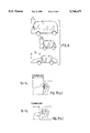
- the specific speed as a limit to which the deformation of the crushable zone can be restrained not to extend to the vehicle cabin is defined as a survival space ensuring speed Va (see FIGS. 7(a), 7(b)) in this specification.
- the object of the present invention is to provide a vehicle collision control system which, after predicting a collision in a manner known in the prior art, decelerates the vehicle to obtain a relation "the collision speed V2 ⁇ the survival space ensuring speed Va" by successively braking while ensuring steady running of the vehicle, and outputs an inflator ignition signal for an air bag device only when an actual collision G is sensed by an impact sensor, thereby effectively operating the occupant restraint protective device such as an air bag device even when the crushable zone of the vehicle is short in the longitudinal direction as mentioned above.
- the present invention is devised to, by detecting a distance between the vehicle and an object in front of the vehicle and a vehicle speed, decide whether the vehicle will collide with the object, compute an expected speed at the collision, and brake to make the speed at the collision lower than the survival space ensuring speed.
- the present invention is characterized by comprising a distance measuring sensor for sensing a distance between the vehicle and an object existing in the running direction, collision predictive means for predicting a collision based on a rate of distance change between the vehicle and the object and then outputting a collision predictive signal to a logic circuit when the collision is predicted, deceleration calculating means for calculating a first limit deceleration as the maximum deceleration within a range allowing the vehicle to run while braking without losing its stability, and a second limit deceleration for making a speed at the collision lower than a survival space ensuring speed, arithmetic processing means for successively comparing the first limit deceleration to the second limit deceleration which change according the running of the vehicle after the collision predictive signal is outputted and for outputting a braking start signal at a point when a predetermined comparative value is obtained, braking command means for commanding a predetermined braking force to braking means upon receiving the braking start signal from the arithmetic processing means, an impact sensor, and
- the first limit deceleration is successively calculated considering a road condition obtained from the vehicle speed and a rotational speed of each wheel.
- the second limit deceleration is successively calculated based on the relation between the distance from the vehicle to the object and the vehicle speed after the collision predictive signal is outputted, and is used for reducing the vehicle speed to the survival space ensuring speed before the collision.
- the predetermined comparative value is a threshold allowing the braking start signal to be outputted at least before the second limit deceleration exceeds the first limit deceleration.
- the braking start signal is immediately outputted.
- the distance measuring sensor senses the distance between the vehicle and an object existing in the running direction of the vehicle and predicts a collision based on a rate of distance change between the vehicle and the object.
- the collision predictive means outputs the collision predictive signal to the logic circuit.
- the deceleration calculating means calculates the first limit deceleration as the maximum deceleration within a range allowing the vehicle to run while braking without losing its stability, and a second limit deceleration for making a speed at the collision lower than a survival space ensuring speed.
- the arithmetic processing means successively compares the first limit deceleration to the second limit deceleration which change according to the running of the vehicle after the collision predictive signal is outputted, and outputs the braking start signal at a point when the predetermined comparative value is obtained.
- the braking commands means command the predetermined braking force to the braking means upon receiving the braking start signal from the arithmetic processing means.
- the collision signal generating means outputs the collision occurrence signal to the logic circuit when the impact sensor senses the collision. When the collision predictive signal and the collision occurrence signal are both inputted to the logic circuit, the logic circuit outputs the ignition signal to the inflator of the air bag device.
- the secure quick braking is started to make the collision speed lower than the survival space ensuring speed which is unique to the vehicle. Therefore, since the collision speed can be made lower than the survival space ensuring speed, the deformation of the vehicle body can be restrained in the range of the crushable zone even which is small, thereby effectively protecting the occupant by the occupant restraint protective device such as an air bag device deployed in the survival space.
- the vehicle Since the first limit deceleration is successively calculated considering the road condition obtained from the vehicle speed and the rotational speed of each wheel, the vehicle never be inoperable by a steering wheel even during the quick braking, thereby braking the vehicle in the steady running state.
- the second limit deceleration is successively calculated based on the relation between the distance from the vehicle to the object and the vehicle speed after the collision predictive signal is outputted, and is used for reducing the vehicle speed to the survival space ensuring speed before the collision, the deformation of the vehicle body at the collision can be restrained within a range allowing the survival space to be ensured.
- the predetermined comparative value is a threshold allowing the braking start signal to be outputted at least before the second limit deceleration exceeds the first limit deceleration, thereby allowing the vehicle to run while braking without losing its stability even when the vehicle is quickly braked upon predicting the collision.
- the braking start signal is immediately outputted, thereby minimizing the breakage of the vehicle at the collision as possible.
- FIG. 1 is a view showing a positional relation between a running vehicle and an object for illustrating a vehicle collision control system according to the present invention
- FIG. 2 is a graphical representation showing an example of changes of decelerations (acceptable maximum deceleration ⁇ Vth and desired deceleration ⁇ Vr) during running controlled by the vehicle collision control system of the present invention
- FIG. 3 is a block diagram showing one embodiment of the structure of the vehicle collision control system according to the present invention.
- FIG. 4 is a flow chart showing an example of the decelerating operation by the vehicle collision control system according to the present invention.
- FIG. 5 is a block schematic diagram showing an example of conventional vehicle collision sensing device
- FIG. 6 is a schematic illustration showing a difference in size of a crushable zone among different types of automobiles.
- FIG. 7(a) and 7(b) are the schematics illustration showing the relation between the collision speed V2 and the survival space ensuring speed Va by using crashed states of a vehicle.
- FIG. 1 is a view of a positional relation schematically illustrating a running vehicle 10 which is in a position D(t1) at a time t1.
- the device measures a distance L between the vehicle 10 and the object 15 and the rate of change in the distance ⁇ D during a time period ⁇ t, thereby computing an expected collision time t2 at which the vehicle collides with the object 15 and a collision speed V2.
- the vehicle 10 shown in FIG. 1 is decelerated from the vehicle speed V1 to the collision speed V2 until the collision by quick braking based on braking command.
- the deceleration ⁇ V by this quick braking excesses the acceptable maximum deceleration ⁇ Vth as a first limit deceleration which changes corresponding to the condition of the running vehicle and the condition of the road surface, the vehicle wheels are locked and the driver can not control by the steering wheel so that the vehicle slips aside.
- another accident may be occurred by the side-slip.
- the acceptable maximum deceleration ⁇ Vth is calculated by detecting a wheel acceleration obtained from the sensed vehicle speed and the wheel rotational speeds, and considering conditions such as whether the vehicle is provided with an anti-skid brake system (ABS) (various systems have been already devised and performed).
- ABS anti-skid brake system
- the acceptable maximum deceleration ⁇ Vth is preferably set considering data about the road surface condition obtained from the result of the wheel rotational speed.
- the survival space ensuring speed Va is unique to each type of body and the structure. Car manufacturers catch accurate values of the survival space ensuring speed Va for each type of vehicle by, such as, collision tests with real vehicles and numerical analysis with a computer.
- the vehicle must be decelerated by fully braking at least a time when the second limit deceleration is equal to the desired deceleration ⁇ Vr as shown in FIG. 2.
- control unit 30 one of the vehicle collision control system according to the present invention, having collision predictive means 31, deceleration calculating means 32, arithmetic processing means 33, braking command means 34, and collision signal generating means 35.
- a distance measuring sensor 20 as an input unit for the collision predictive means 31 is mounted in the front portion of the vehicle body.
- the distance measuring sensor 20 senses the existence of an object in the running direction of the vehicle.
- the distance measuring sensor 20 may be an optical distance measuring sensor or an ultrasonic distance measuring sensor, which can search forward areas in the running direction at predetermined intervals and sense the distance between the vehicle and the object during running.
- the distance data from the measuring sensor 20 is outputted to the control unit 30.
- the control unit 30 is provided with the collision predictive means 31.
- the collision predictive means 31 decides whether the vehicle will collide with the object by performing arithmetic on the distance data.
- the collision predictive means 31 consists of the same logic as that of the aforementioned collision predictive means of the prior art. That is, the collision predictive means computes a distance between the vehicle and the forward object, and change in the speed of vehicle running toward the object based on the rate of distance change, considering the expected collision time and the maximum deceleration of the vehicle, and decides whether the vehicle will collides with the object.
- a collision predictive signal S1 is outputted to an logic circuit 36 which decides to generate the inflator ignition signal.
- the deceleration calculating means 32 Upon generating the collision predictive signal S1 from the collision predictive means 31, the deceleration calculating means 32 calculate the acceptable maximum deceleration ⁇ Vth which allows the vehicle to be prevented from slipping due to the locked state of the wheels.
- the deceleration calculating means 32 calculates wheel rotational speeds and wheel accelerations upon converting an analog rotational speed signal sensed by the wheel rotational speed sensor to a digital signal as mentioned above. It is detected that the wheels will be locked based on the wheel accelerations and the vehicle speed at this point. Then the deceleration calculating means 32 calculates the acceptable maximum deceleration ⁇ Vth within the range in which the wheels may be never locked.
- the deceleration calculating means 32 also sets the desired deceleration ⁇ Vr which is needed to reduce the speed V1 to make the speed V2 lower than the survival space ensuring speed Va or less before the collision. That is, the deceleration calculating means 32 calculates the acceptable maximum deceleration ⁇ Vth and the desired deceleration ⁇ Vr at the time ti.
- the arithmetic processing means 33 After the collision predictive signal S1 is outputted, the arithmetic processing means 33 performs comparison arithmetic between the acceptable maximum deceleration ⁇ Vth and the desired deceleration ⁇ Vr at the time ti at the predetermined interval ( ⁇ t) , and outputs a predetermined working command signal to the braking command means 34 using a threshold at which the desired deceleration ⁇ Vr is equal to the acceptable maximum deceleration ⁇ Vth. It should be understood that when the desired deceleration ⁇ Vr already exceeds the acceptable deceleration ⁇ Vth, the braking command signal is preferably outputted immediately (see t' in FIG. 2).
- the braking command signal is outputted to the braking command means 34 to keep the full-braking state in the range in which the acceptable maximum deceleration ⁇ Vth is satisfied. Then the braking command means 34 outputs a driving signal to each drive of braking means 40 installed for each wheel. Since each of the braking means 40 comprises an electromagnetic valve and a brake actuator such as a hydraulic pump, the braking command means 34 outputs a solenoid driving signal for the electromagnetic valve (not shown) and a driving signal for a motor relay of the pump.
- the vehicle is provided with an impact sensor 21 in the front portion thereof.
- the impact sensor 21 may be any type of acceleration G sensor well-known in the art, such as a seismic impact sensor which is of electric contact type or mechanical type.
- the impact sensor 21 is set in its sensitivity to sense an impact acceleration at the collision whereby the vehicle is broken.
- the collision signal generating means 35 outputs the collision occurrence signal S2 to the logic circuit 36.
- the logic circuit 36 outputs an ignition signal Ss to the inflator 42 of the air bag device 41 only when both signals S1 and S2 are obtained upon receiving the collision predictive signal outputted from the collision predictive means 31.
- the distance measuring sensor 20 performs the sensing for an object at the predetermined time interval during running.
- the operation of the collision control system according to the flow chart of FIG. 4 is started.
- the distance measuring sensor 20 also senses the distance D(t1) between the vehicle and the object 15 at the time t1 at when the object 15 is sensed and further computes the time t2 at when the vehicle will reach the object 15 (Step 100).
- the vehicle speed is sensed during the time period ⁇ t, the rate of distance change ⁇ D between the vehicle and the object 15 (Step 110), and the comparison is performed between the rate of distance change ⁇ D and a collision occurrence threshold (Step 120).
- the collision occurrence threshold changes according to the driving condition set from the deceleration and the limit braking capacity of the vehicle.
- the rate of distance change ⁇ D exceeds the collision occurrence threshold, that is, that the collision time is earlier than a stopping time calculated by the rate of distance change ⁇ D
- the collision occurrence is predicted. Therefore, the system can also recognize an unavoidable collision due to rapid approach of the object 15.
- the collision predictive signal S1 is outputted to the logic circuit 36 (Step 130).
- the system senses each rotational speed of the wheels, calculates the wheel acceleration based on the detected signals, and further calculates the acceptable maximum deceleration ⁇ Vth for ensuring steady running of the vehicle during quick braking, and the desired deceleration ⁇ Vr which is needed to reduce the speed V1 to the survival space ensuring speed Va or less before the collision (Steps 140, 150).
- the arithmetic processing means 33 compares the acceptable maximum deceleration ⁇ Vth to the desired deceleration ⁇ Vr detected successively at the predetermined interval ( ⁇ t) (Step 160) and outputs the braking command signal to the braking command means 34 at least before the desired deceleration ⁇ Vr exceeds the acceptable maximum deceleration ⁇ Vth (Step 170).
- the braking command means 34 controls the braking force not to allow the actual deceleration ⁇ V to exceed the acceptable maximum deceleration ⁇ Vth (Step 180).
- the braking command means 34 when the steady running of the vehicle cannot be ensured due to the quick braking, the braking command means 34 outputs a brake actuator pressure reducing signal for decreasing the braking force so as to ensure the steady running of the vehicle while fully braked.
- the braking command means 34 when the braking deceleration is lower than the expected deceleration according to the relation with the desired deceleration ⁇ Vr, the braking command means 34 output the brake actuator pressure intensifying signal for increasing the braking force so as to sufficiently brake the vehicle. In this manner, the actual deceleration ⁇ V is continuously held around the acceptable maximum deceleration ⁇ Vth until the collision while the full-braking state is held.
- the process for controlling the speed loops the braking command until the time t2 in the control circuit 30 (Step 190).
- the impact sensor 21 positioned in the front portion of the vehicle senses the collision (Step 200).
- the impact sensor 21 senses that the impact applied to the vehicle body is larger than the threshold (Step 210)
- the collision occurrence signal S2 is outputted to the logic circuit 36 (Step 220).
- the logic circuit 36 Only when the collision predictive signal S1 mentioned above and the collision occurrence signal S2 both are inputted to the logic circuit 36, the logic circuit 36 generates an ignition signal Ss for the inflator 42 of the air bag device 41 (Step 230).
- the collision occurrence signal S2 is not outputted so that the air bag can be prevented from being incorrectly deployed.
- the collision control system can securely ensure the effect of the occupant restraint protective device such as an air bag device even with the vehicle having the crushable zone of which is short in the longitudinal direction.
Abstract
Description
Claims (5)
Applications Claiming Priority (2)
| Application Number | Priority Date | Filing Date | Title |
|---|---|---|---|
| JP6-335538 | 1994-12-20 | ||
| JP33553894A JP3467339B2 (en) | 1994-12-20 | 1994-12-20 | Vehicle collision state control system |
Publications (1)
| Publication Number | Publication Date |
|---|---|
| US5748477A true US5748477A (en) | 1998-05-05 |
Family
ID=18289700
Family Applications (1)
| Application Number | Title | Priority Date | Filing Date |
|---|---|---|---|
| US08/574,553 Expired - Lifetime US5748477A (en) | 1994-12-20 | 1995-12-19 | Vehicle collision control system |
Country Status (2)
| Country | Link |
|---|---|
| US (1) | US5748477A (en) |
| JP (1) | JP3467339B2 (en) |
Cited By (50)
| Publication number | Priority date | Publication date | Assignee | Title |
|---|---|---|---|---|
| US5835007A (en) * | 1997-02-10 | 1998-11-10 | Delco Electronics Corporation | Method and apparatus for crash sensing using anticipatory sensor inputs |
| US6021375A (en) * | 1998-01-13 | 2000-02-01 | Honda Giken Kogyo Kabushiki Kaisha | Vehicle safety running control system |
| US6031449A (en) * | 1997-06-23 | 2000-02-29 | Gec Alsthom Transport Sa | Method of protection against impacts between two vehicles by at least on inflatable member and device for implementing it |
| US6271747B1 (en) | 1998-04-18 | 2001-08-07 | Daimlerchrysler Ag | Method for adjusting the trigger threshold of vehicle occupant protection devices |
| US6289332B2 (en) | 1999-02-26 | 2001-09-11 | Freightliner Corporation | Integrated message display system for a vehicle |
| US6312013B1 (en) * | 1998-11-25 | 2001-11-06 | Daimlerchrysler Ag | Method of updating the trigger threshold of a passive safety system |
| US6359553B1 (en) * | 1998-06-26 | 2002-03-19 | Volkswagen Ag | Method and control arrangement for minimizing consequences of accidents |
| US6462649B1 (en) * | 1999-01-26 | 2002-10-08 | Nissan Motor Co. | Air bag failure display system and method |
| US6473681B1 (en) * | 1998-04-18 | 2002-10-29 | Continental Teves Ag & Co., Ohg | Method for reducing braking distance |
| US6496764B1 (en) | 2001-08-23 | 2002-12-17 | General Motors Corporation | Vehicle impact-sensing method with improved severity discrimination |
| US6498972B1 (en) | 2002-02-13 | 2002-12-24 | Ford Global Technologies, Inc. | Method for operating a pre-crash sensing system in a vehicle having a countermeasure system |
| US6512969B1 (en) | 2001-08-23 | 2003-01-28 | General Motors Corporation | Vehicle sensing system using biased severity measure |
| US6519519B1 (en) | 2002-02-01 | 2003-02-11 | Ford Global Technologies, Inc. | Passive countermeasure methods |
| US20030076981A1 (en) * | 2001-10-18 | 2003-04-24 | Smith Gregory Hugh | Method for operating a pre-crash sensing system in a vehicle having a counter-measure system |
| US6560520B2 (en) * | 1999-08-04 | 2003-05-06 | Takata Corporation | Vehicle collision damage reduction system |
| US6571161B2 (en) | 2001-01-22 | 2003-05-27 | General Motors Corporation | Pre-crash assessment of crash severity for road vehicles |
| US20030139864A1 (en) * | 2002-01-24 | 2003-07-24 | Ford Global Technologies, Inc. | Post collision restraints control module |
| US6721659B2 (en) * | 2002-02-01 | 2004-04-13 | Ford Global Technologies, Llc | Collision warning and safety countermeasure system |
| US20040111200A1 (en) * | 2001-11-29 | 2004-06-10 | Rao Manoharprasad K. | Vehicle sensing based pre-crash threat assessment system |
| US6775605B2 (en) | 2001-11-29 | 2004-08-10 | Ford Global Technologies, Llc | Remote sensing based pre-crash threat assessment system |
| US6831572B2 (en) | 2002-01-29 | 2004-12-14 | Ford Global Technologies, Llc | Rear collision warning system |
| US20040254729A1 (en) * | 2003-01-31 | 2004-12-16 | Browne Alan L. | Pre-collision assessment of potential collision severity for road vehicles |
| US6851504B2 (en) | 1998-12-14 | 2005-02-08 | Trw Vehicle Safety Systems Inc. | Method and apparatus for anticipating a vehicle crash event |
| US20050065688A1 (en) * | 2003-09-23 | 2005-03-24 | Ford Global Technologies, Llc | Method for operating a vehicle crash safety system in a vehicle having a pre-crash sensing system and countermeasure systems |
| US20050107955A1 (en) * | 2003-11-13 | 2005-05-19 | Denso Corporation | Collision-prediction unit for a vehicle |
| WO2005070742A1 (en) * | 2004-01-26 | 2005-08-04 | Bombardier Transportation Gmbh | Method for preventing a track-bound vehicle from overrunning an obstacle and track-bound vehicle |
| GB2416419A (en) * | 2004-07-19 | 2006-01-25 | Autoliv Dev | Triggering A Vehicle Safety Device |
| US7009500B2 (en) | 2002-02-13 | 2006-03-07 | Ford Global Technologies, Llc | Method for operating a pre-crash sensing system in a vehicle having a countermeasure system using stereo cameras |
| US20060055520A1 (en) * | 2004-09-13 | 2006-03-16 | Spencer Irvine | Actuated braking and distance sensing system for operational regulation of belt loader equipment |
| US20060173621A1 (en) * | 2004-03-31 | 2006-08-03 | Lawrence Stopczynski | Collision mitigation system |
| US20060198553A1 (en) * | 2005-02-16 | 2006-09-07 | Volker Heer | Digital flat detector for detecting x-radiation |
| US20060237960A1 (en) * | 2003-01-21 | 2006-10-26 | Toshiya Kudo | Seat belt device for vehicle |
| US20070021892A1 (en) * | 2005-07-20 | 2007-01-25 | Nissan Motor Co., Ltd. | Seat belt controlling system and method of controlling seat belt |
| US7284769B2 (en) * | 1995-06-07 | 2007-10-23 | Automotive Technologies International, Inc. | Method and apparatus for sensing a vehicle crash |
| US20080071446A1 (en) * | 2004-04-30 | 2008-03-20 | Daimlerchrysler Ag | Method for Controlling a Safety-Relevant Component of a Motor Vehicle and Motor Vehicle Comprising a Preventively Activated Safety System |
| US20080134782A1 (en) * | 2004-04-02 | 2008-06-12 | Robert Bosch Gmbh | Multifunctional Upfront Sensor |
| US20080147280A1 (en) * | 1995-06-07 | 2008-06-19 | Automotive Technologies International, Inc. | Method and apparatus for sensing a rollover |
| US20090037055A1 (en) * | 2004-12-24 | 2009-02-05 | Daimlerchrysler Ag | Method and Apparatus for Avoiding or Mitigating Vehicle Collisions |
| US20090121852A1 (en) * | 2007-11-13 | 2009-05-14 | Karsten Breuer | Vehicle obstruction warning system and method |
| US20100007200A1 (en) * | 2008-07-10 | 2010-01-14 | Robert Bosch Gmbh | Deceleration control for a vehicle |
| US20130110370A1 (en) * | 2011-11-02 | 2013-05-02 | Toyota Jidosha Kabushiki Kaisha | Brake control device |
| US20170305341A1 (en) * | 2014-08-21 | 2017-10-26 | Valeo Schalter Und Sensoren Gmbh | Method for warning a driver of a vehicle of the presence of an object in the surroundings, driver assistance system and motor vehicle |
| CN105270365B (en) * | 2014-06-16 | 2018-01-26 | 本田技研工业株式会社 | Controller of vehicle |
| US11046266B1 (en) | 2018-06-04 | 2021-06-29 | State Farm Mutual Automobile Insurance Company | System and method for dampening impact to a vehicle |
| CN114043956A (en) * | 2021-11-15 | 2022-02-15 | 东风柳州汽车有限公司 | Air bag grading explosion control method, device, equipment and storage medium |
| US11352017B2 (en) | 2018-07-13 | 2022-06-07 | State Farm Mutual Automobile Insurance Company | Dynamic safe storage of vehicle content |
| US11400834B2 (en) | 2018-02-02 | 2022-08-02 | State Farm Mutual Automobile Insurance Company | Adjusting interior configuration of a vehicle based on external environment data |
| US11485254B2 (en) | 2018-04-09 | 2022-11-01 | State Farm Mutual Automobile Insurance Company | System and method for adjusting an interior configuration of a vehicle in response to a vehicular accident |
| US11554736B2 (en) | 2018-07-13 | 2023-01-17 | State Farm Mutual Automobile Insurance Company | Adjusting interior configuration of a vehicle based on vehicle contents |
| US11840243B2 (en) | 2018-07-13 | 2023-12-12 | State Farm Mutual Automobile Insurance Company | Dynamic limiting of vehicle operation based on interior configurations |
Families Citing this family (5)
| Publication number | Priority date | Publication date | Assignee | Title |
|---|---|---|---|---|
| KR20010086494A (en) * | 2000-03-02 | 2001-09-13 | 윤장진 | Early crash sensor |
| DE10348388B4 (en) * | 2003-10-17 | 2016-02-04 | Robert Bosch Gmbh | Device for determining a contact time of a vehicle with an impact object |
| DE102004057604B4 (en) * | 2004-11-29 | 2014-04-30 | Daimler Ag | Method for a safety system in a vehicle |
| JP2006240367A (en) * | 2005-03-01 | 2006-09-14 | Toyota Motor Corp | Occupant crash protection device |
| JP2007216737A (en) | 2006-02-14 | 2007-08-30 | Hitachi Ltd | Collision safety controller for vehicle |
Citations (12)
| Publication number | Priority date | Publication date | Assignee | Title |
|---|---|---|---|---|
| US3835361A (en) * | 1973-08-10 | 1974-09-10 | Gen Motors Corp | Automatic proximity braking system for motor vehicles |
| US4146891A (en) * | 1976-07-28 | 1979-03-27 | Mitsubishi Denki Kabushiki Kaisha | Vehicle collision preventing apparatus |
| US4308536A (en) * | 1979-02-26 | 1981-12-29 | Collision Avoidance Systems | Anti-collision vehicular radar system |
| US5249157A (en) * | 1990-08-22 | 1993-09-28 | Kollmorgen Corporation | Collision avoidance system |
| US5285188A (en) * | 1991-06-07 | 1994-02-08 | Takata Corporation | Vehicle collision detecting system |
| US5410484A (en) * | 1991-06-05 | 1995-04-25 | Akebono Brake Industry Co., Ltd. | Automatic brake control system |
| US5418727A (en) * | 1992-06-02 | 1995-05-23 | Mazda Motor Corporation | Control apparatus for ensuring safety of a vehicle run |
| US5502432A (en) * | 1991-12-16 | 1996-03-26 | Stanley Electric Co., Ltd. | Apparatus and method of warning rear-end collision |
| US5529138A (en) * | 1993-01-22 | 1996-06-25 | Shaw; David C. H. | Vehicle collision avoidance system |
| US5541590A (en) * | 1992-08-04 | 1996-07-30 | Takata Corporation | Vehicle crash predictive and evasive operation system by neural networks |
| US5572428A (en) * | 1993-09-30 | 1996-11-05 | Honda Giken Kogyo Kabushiki Kaisha | Anti-collision system for vehicles |
| US5594414A (en) * | 1994-08-02 | 1997-01-14 | Namngani; Abdulatif | Collision probability detection system |
-
1994
- 1994-12-20 JP JP33553894A patent/JP3467339B2/en not_active Expired - Fee Related
-
1995
- 1995-12-19 US US08/574,553 patent/US5748477A/en not_active Expired - Lifetime
Patent Citations (12)
| Publication number | Priority date | Publication date | Assignee | Title |
|---|---|---|---|---|
| US3835361A (en) * | 1973-08-10 | 1974-09-10 | Gen Motors Corp | Automatic proximity braking system for motor vehicles |
| US4146891A (en) * | 1976-07-28 | 1979-03-27 | Mitsubishi Denki Kabushiki Kaisha | Vehicle collision preventing apparatus |
| US4308536A (en) * | 1979-02-26 | 1981-12-29 | Collision Avoidance Systems | Anti-collision vehicular radar system |
| US5249157A (en) * | 1990-08-22 | 1993-09-28 | Kollmorgen Corporation | Collision avoidance system |
| US5410484A (en) * | 1991-06-05 | 1995-04-25 | Akebono Brake Industry Co., Ltd. | Automatic brake control system |
| US5285188A (en) * | 1991-06-07 | 1994-02-08 | Takata Corporation | Vehicle collision detecting system |
| US5502432A (en) * | 1991-12-16 | 1996-03-26 | Stanley Electric Co., Ltd. | Apparatus and method of warning rear-end collision |
| US5418727A (en) * | 1992-06-02 | 1995-05-23 | Mazda Motor Corporation | Control apparatus for ensuring safety of a vehicle run |
| US5541590A (en) * | 1992-08-04 | 1996-07-30 | Takata Corporation | Vehicle crash predictive and evasive operation system by neural networks |
| US5529138A (en) * | 1993-01-22 | 1996-06-25 | Shaw; David C. H. | Vehicle collision avoidance system |
| US5572428A (en) * | 1993-09-30 | 1996-11-05 | Honda Giken Kogyo Kabushiki Kaisha | Anti-collision system for vehicles |
| US5594414A (en) * | 1994-08-02 | 1997-01-14 | Namngani; Abdulatif | Collision probability detection system |
Cited By (71)
| Publication number | Priority date | Publication date | Assignee | Title |
|---|---|---|---|---|
| US7284769B2 (en) * | 1995-06-07 | 2007-10-23 | Automotive Technologies International, Inc. | Method and apparatus for sensing a vehicle crash |
| US20080147280A1 (en) * | 1995-06-07 | 2008-06-19 | Automotive Technologies International, Inc. | Method and apparatus for sensing a rollover |
| US5835007A (en) * | 1997-02-10 | 1998-11-10 | Delco Electronics Corporation | Method and apparatus for crash sensing using anticipatory sensor inputs |
| US6031449A (en) * | 1997-06-23 | 2000-02-29 | Gec Alsthom Transport Sa | Method of protection against impacts between two vehicles by at least on inflatable member and device for implementing it |
| US6021375A (en) * | 1998-01-13 | 2000-02-01 | Honda Giken Kogyo Kabushiki Kaisha | Vehicle safety running control system |
| US6271747B1 (en) | 1998-04-18 | 2001-08-07 | Daimlerchrysler Ag | Method for adjusting the trigger threshold of vehicle occupant protection devices |
| US6473681B1 (en) * | 1998-04-18 | 2002-10-29 | Continental Teves Ag & Co., Ohg | Method for reducing braking distance |
| US6359553B1 (en) * | 1998-06-26 | 2002-03-19 | Volkswagen Ag | Method and control arrangement for minimizing consequences of accidents |
| US6312013B1 (en) * | 1998-11-25 | 2001-11-06 | Daimlerchrysler Ag | Method of updating the trigger threshold of a passive safety system |
| US6851504B2 (en) | 1998-12-14 | 2005-02-08 | Trw Vehicle Safety Systems Inc. | Method and apparatus for anticipating a vehicle crash event |
| US6462649B1 (en) * | 1999-01-26 | 2002-10-08 | Nissan Motor Co. | Air bag failure display system and method |
| US6289332B2 (en) | 1999-02-26 | 2001-09-11 | Freightliner Corporation | Integrated message display system for a vehicle |
| US6560520B2 (en) * | 1999-08-04 | 2003-05-06 | Takata Corporation | Vehicle collision damage reduction system |
| US6574540B2 (en) * | 1999-08-04 | 2003-06-03 | Takata Corporation | Vehicle collision damage reduction system |
| US6571161B2 (en) | 2001-01-22 | 2003-05-27 | General Motors Corporation | Pre-crash assessment of crash severity for road vehicles |
| US8321092B2 (en) | 2001-01-22 | 2012-11-27 | GM Global Technology Operations LLC | Pre-collision assessment of potential collision severity for road vehicles |
| US6496764B1 (en) | 2001-08-23 | 2002-12-17 | General Motors Corporation | Vehicle impact-sensing method with improved severity discrimination |
| US6512969B1 (en) | 2001-08-23 | 2003-01-28 | General Motors Corporation | Vehicle sensing system using biased severity measure |
| US20030076981A1 (en) * | 2001-10-18 | 2003-04-24 | Smith Gregory Hugh | Method for operating a pre-crash sensing system in a vehicle having a counter-measure system |
| US6819991B2 (en) | 2001-11-29 | 2004-11-16 | Ford Global Technologies, Llc | Vehicle sensing based pre-crash threat assessment system |
| US6775605B2 (en) | 2001-11-29 | 2004-08-10 | Ford Global Technologies, Llc | Remote sensing based pre-crash threat assessment system |
| US20040111200A1 (en) * | 2001-11-29 | 2004-06-10 | Rao Manoharprasad K. | Vehicle sensing based pre-crash threat assessment system |
| US20030139864A1 (en) * | 2002-01-24 | 2003-07-24 | Ford Global Technologies, Inc. | Post collision restraints control module |
| US7158870B2 (en) | 2002-01-24 | 2007-01-02 | Ford Global Technologies, Llc | Post collision restraints control module |
| US6831572B2 (en) | 2002-01-29 | 2004-12-14 | Ford Global Technologies, Llc | Rear collision warning system |
| US6721659B2 (en) * | 2002-02-01 | 2004-04-13 | Ford Global Technologies, Llc | Collision warning and safety countermeasure system |
| US6519519B1 (en) | 2002-02-01 | 2003-02-11 | Ford Global Technologies, Inc. | Passive countermeasure methods |
| US6498972B1 (en) | 2002-02-13 | 2002-12-24 | Ford Global Technologies, Inc. | Method for operating a pre-crash sensing system in a vehicle having a countermeasure system |
| US7009500B2 (en) | 2002-02-13 | 2006-03-07 | Ford Global Technologies, Llc | Method for operating a pre-crash sensing system in a vehicle having a countermeasure system using stereo cameras |
| US20060237960A1 (en) * | 2003-01-21 | 2006-10-26 | Toshiya Kudo | Seat belt device for vehicle |
| US7654573B2 (en) * | 2003-01-21 | 2010-02-02 | Toyota Jidosha Kabushiki Kasha | Seat belt device for vehicle |
| US20040254729A1 (en) * | 2003-01-31 | 2004-12-16 | Browne Alan L. | Pre-collision assessment of potential collision severity for road vehicles |
| US6915196B2 (en) | 2003-09-23 | 2005-07-05 | Ford Global Technologies, Llc | Method for operating a vehicle crash safety system in a vehicle having a pre-crash sensing system and countermeasure systems |
| US20050065688A1 (en) * | 2003-09-23 | 2005-03-24 | Ford Global Technologies, Llc | Method for operating a vehicle crash safety system in a vehicle having a pre-crash sensing system and countermeasure systems |
| US20050107955A1 (en) * | 2003-11-13 | 2005-05-19 | Denso Corporation | Collision-prediction unit for a vehicle |
| US7184889B2 (en) * | 2003-11-13 | 2007-02-27 | Denso Corporation | Collision-prediction unit for a vehicle |
| WO2005070742A1 (en) * | 2004-01-26 | 2005-08-04 | Bombardier Transportation Gmbh | Method for preventing a track-bound vehicle from overrunning an obstacle and track-bound vehicle |
| US7197396B2 (en) * | 2004-03-31 | 2007-03-27 | Ford Global Technologies, Llc | Collision mitigation system |
| US20060173621A1 (en) * | 2004-03-31 | 2006-08-03 | Lawrence Stopczynski | Collision mitigation system |
| US20080134782A1 (en) * | 2004-04-02 | 2008-06-12 | Robert Bosch Gmbh | Multifunctional Upfront Sensor |
| US20080071446A1 (en) * | 2004-04-30 | 2008-03-20 | Daimlerchrysler Ag | Method for Controlling a Safety-Relevant Component of a Motor Vehicle and Motor Vehicle Comprising a Preventively Activated Safety System |
| GB2416419B (en) * | 2004-07-19 | 2008-10-15 | Autoliv Dev | Improvements in or relating to an arrangement for triggering a vehicle safety device |
| CN1989027B (en) * | 2004-07-19 | 2010-07-21 | 奥托立夫开发公司 | Device for triggering a vehicle safety device |
| US7983818B2 (en) | 2004-07-19 | 2011-07-19 | Autoliv Development Ab | Arrangement for triggering a vehicle safety device |
| GB2416419A (en) * | 2004-07-19 | 2006-01-25 | Autoliv Dev | Triggering A Vehicle Safety Device |
| US20080215211A1 (en) * | 2004-07-19 | 2008-09-04 | Autoliv Development Ab | Arrangement For Triggering a Vehicle Safety Device |
| US7268676B2 (en) | 2004-09-13 | 2007-09-11 | Spencer Irvine | Actuated braking and distance sensing system for operational regulation of belt loader equipment |
| US7583183B2 (en) | 2004-09-13 | 2009-09-01 | Spencer Irvine | Actuated braking and distance sensing system for operational regulation of belt loader equipment |
| US20070290824A1 (en) * | 2004-09-13 | 2007-12-20 | Spencer Irvine | Actuated braking and distance sensing system for operational regulation of belt loader equipment |
| US20060055520A1 (en) * | 2004-09-13 | 2006-03-16 | Spencer Irvine | Actuated braking and distance sensing system for operational regulation of belt loader equipment |
| US20090037055A1 (en) * | 2004-12-24 | 2009-02-05 | Daimlerchrysler Ag | Method and Apparatus for Avoiding or Mitigating Vehicle Collisions |
| US8150583B2 (en) * | 2004-12-24 | 2012-04-03 | Daimler Ag | Method and apparatus for avoiding or mitigating vehicle collisions |
| US20060198553A1 (en) * | 2005-02-16 | 2006-09-07 | Volker Heer | Digital flat detector for detecting x-radiation |
| US20070021892A1 (en) * | 2005-07-20 | 2007-01-25 | Nissan Motor Co., Ltd. | Seat belt controlling system and method of controlling seat belt |
| US8013722B2 (en) * | 2007-11-13 | 2011-09-06 | Wabco Gmbh | Vehicle obstruction warning system and method |
| US20090121852A1 (en) * | 2007-11-13 | 2009-05-14 | Karsten Breuer | Vehicle obstruction warning system and method |
| US20100007200A1 (en) * | 2008-07-10 | 2010-01-14 | Robert Bosch Gmbh | Deceleration control for a vehicle |
| US8256851B2 (en) | 2008-07-10 | 2012-09-04 | Robert Bosch Gmbh | Deceleration control for a vehicle |
| US20130110370A1 (en) * | 2011-11-02 | 2013-05-02 | Toyota Jidosha Kabushiki Kaisha | Brake control device |
| CN105270365B (en) * | 2014-06-16 | 2018-01-26 | 本田技研工业株式会社 | Controller of vehicle |
| US20170305341A1 (en) * | 2014-08-21 | 2017-10-26 | Valeo Schalter Und Sensoren Gmbh | Method for warning a driver of a vehicle of the presence of an object in the surroundings, driver assistance system and motor vehicle |
| US10124727B2 (en) * | 2014-08-21 | 2018-11-13 | Valeo Schalter Und Sensoren Gmbh | Method for warning a driver of a vehicle of the presence of an object in the surroundings, driver assistance system and motor vehicle |
| US11400834B2 (en) | 2018-02-02 | 2022-08-02 | State Farm Mutual Automobile Insurance Company | Adjusting interior configuration of a vehicle based on external environment data |
| US11485254B2 (en) | 2018-04-09 | 2022-11-01 | State Farm Mutual Automobile Insurance Company | System and method for adjusting an interior configuration of a vehicle in response to a vehicular accident |
| US11046266B1 (en) | 2018-06-04 | 2021-06-29 | State Farm Mutual Automobile Insurance Company | System and method for dampening impact to a vehicle |
| US11820306B2 (en) | 2018-06-04 | 2023-11-21 | State Farm Mutual Automobile Insurance Company | System and method for dampening impact to a vehicle |
| US11352017B2 (en) | 2018-07-13 | 2022-06-07 | State Farm Mutual Automobile Insurance Company | Dynamic safe storage of vehicle content |
| US11554736B2 (en) | 2018-07-13 | 2023-01-17 | State Farm Mutual Automobile Insurance Company | Adjusting interior configuration of a vehicle based on vehicle contents |
| US11623651B2 (en) | 2018-07-13 | 2023-04-11 | State Farm Mutual Automobile Insurance Company | Dynamic safe storage of vehicle content |
| US11840243B2 (en) | 2018-07-13 | 2023-12-12 | State Farm Mutual Automobile Insurance Company | Dynamic limiting of vehicle operation based on interior configurations |
| CN114043956A (en) * | 2021-11-15 | 2022-02-15 | 东风柳州汽车有限公司 | Air bag grading explosion control method, device, equipment and storage medium |
Also Published As
| Publication number | Publication date |
|---|---|
| JPH08169297A (en) | 1996-07-02 |
| JP3467339B2 (en) | 2003-11-17 |
Similar Documents
| Publication | Publication Date | Title |
|---|---|---|
| US5748477A (en) | Vehicle collision control system | |
| US7353905B2 (en) | Method for actuating a reversible vehicle occupant protection means in a motor vehicle | |
| US6370461B1 (en) | Crash control system for vehicles employing predictive pre-crash signals | |
| US6758495B2 (en) | Method and safety restraint device for restraining an occupant on a vehicle seat | |
| US7706946B2 (en) | Safety system for vehicle occupants | |
| US7051830B2 (en) | Occupant protection system, vehicle using same and occupant protection method | |
| US8244437B2 (en) | Method and system for restraint deployment using lateral kinetic energy | |
| KR102131448B1 (en) | Apparatus for protecting a passenger of an autombile | |
| US20080021617A1 (en) | Method for Actuating a Vehicle Occupant Protection Device in a Vehicle and a Vehicle Occupant Protection System | |
| US7954590B2 (en) | Method for a preventive-action protection system in a motor vehicle | |
| US20040216939A1 (en) | Occupant restraining system with a belt force limiting device | |
| EP1208021B1 (en) | Controller for occupant restraint system | |
| US20090024282A1 (en) | Method for a Preventive-Action Protection System In a Motor Vehicle Having an Inter-Vehicle Distance Sensor System | |
| US6196580B1 (en) | Method of controlling an active occupant-head protection system in a vehicle | |
| US20090150028A1 (en) | Motor vehicle with a safety system with a preventive action | |
| KR100581044B1 (en) | Occupant restraint system | |
| Chan | A treatise on crash sensing for automotive air bag systems | |
| JP3858592B2 (en) | Crew protection device | |
| KR100666360B1 (en) | Apparatus for preventing car crash based on vehicle dynamics | |
| JP4133749B2 (en) | Vehicle seat belt device | |
| US8478488B2 (en) | Impact event countermeasure control method and system for automotive vehicle | |
| US20080284243A1 (en) | Method for a Preventive-Action Protection System in a Motor Vehicle | |
| JP6848478B2 (en) | Secondary collision suppression device | |
| KR101430190B1 (en) | Automobile and control method thereof | |
| KR100552734B1 (en) | air bag system for automotive vehicles and control method thereof |
Legal Events
| Date | Code | Title | Description |
|---|---|---|---|
| AS | Assignment |
Owner name: TAKATA CORPORATION, JAPAN Free format text: ASSIGNMENT OF ASSIGNORS INTEREST;ASSIGNOR:KATOH, SHIGERU;REEL/FRAME:007843/0574 Effective date: 19960105 |
|
| FEPP | Fee payment procedure |
Free format text: PAYOR NUMBER ASSIGNED (ORIGINAL EVENT CODE: ASPN); ENTITY STATUS OF PATENT OWNER: LARGE ENTITY |
|
| STCF | Information on status: patent grant |
Free format text: PATENTED CASE |
|
| FEPP | Fee payment procedure |
Free format text: PAYER NUMBER DE-ASSIGNED (ORIGINAL EVENT CODE: RMPN); ENTITY STATUS OF PATENT OWNER: LARGE ENTITY Free format text: PAYOR NUMBER ASSIGNED (ORIGINAL EVENT CODE: ASPN); ENTITY STATUS OF PATENT OWNER: LARGE ENTITY |
|
| FPAY | Fee payment |
Year of fee payment: 4 |
|
| FPAY | Fee payment |
Year of fee payment: 8 |
|
| FEPP | Fee payment procedure |
Free format text: PAYER NUMBER DE-ASSIGNED (ORIGINAL EVENT CODE: RMPN); ENTITY STATUS OF PATENT OWNER: LARGE ENTITY Free format text: PAYOR NUMBER ASSIGNED (ORIGINAL EVENT CODE: ASPN); ENTITY STATUS OF PATENT OWNER: LARGE ENTITY |
|
| FPAY | Fee payment |
Year of fee payment: 12 |