US5742238A - System for communication between a central controller and items in a factory using infrared light - Google Patents
System for communication between a central controller and items in a factory using infrared light Download PDFInfo
- Publication number
- US5742238A US5742238A US08/522,692 US52269295A US5742238A US 5742238 A US5742238 A US 5742238A US 52269295 A US52269295 A US 52269295A US 5742238 A US5742238 A US 5742238A
- Authority
- US
- United States
- Prior art keywords
- microterminal
- messages
- microterminals
- mode
- microcontroller
- Prior art date
- Legal status (The legal status is an assumption and is not a legal conclusion. Google has not performed a legal analysis and makes no representation as to the accuracy of the status listed.)
- Expired - Lifetime
Links
Images


Classifications
-
- H—ELECTRICITY
- H04—ELECTRIC COMMUNICATION TECHNIQUE
- H04W—WIRELESS COMMUNICATION NETWORKS
- H04W88/00—Devices specially adapted for wireless communication networks, e.g. terminals, base stations or access point devices
- H04W88/02—Terminal devices
-
- G—PHYSICS
- G08—SIGNALLING
- G08B—SIGNALLING OR CALLING SYSTEMS; ORDER TELEGRAPHS; ALARM SYSTEMS
- G08B3/00—Audible signalling systems; Audible personal calling systems
- G08B3/10—Audible signalling systems; Audible personal calling systems using electric transmission; using electromagnetic transmission
- G08B3/1008—Personal calling arrangements or devices, i.e. paging systems
- G08B3/1016—Personal calling arrangements or devices, i.e. paging systems using wireless transmission
- G08B3/1083—Pager locating systems
-
- H—ELECTRICITY
- H04—ELECTRIC COMMUNICATION TECHNIQUE
- H04L—TRANSMISSION OF DIGITAL INFORMATION, e.g. TELEGRAPHIC COMMUNICATION
- H04L12/00—Data switching networks
- H04L12/02—Details
- H04L12/12—Arrangements for remote connection or disconnection of substations or of equipment thereof
-
- H—ELECTRICITY
- H04—ELECTRIC COMMUNICATION TECHNIQUE
- H04W—WIRELESS COMMUNICATION NETWORKS
- H04W88/00—Devices specially adapted for wireless communication networks, e.g. terminals, base stations or access point devices
- H04W88/08—Access point devices
-
- Y—GENERAL TAGGING OF NEW TECHNOLOGICAL DEVELOPMENTS; GENERAL TAGGING OF CROSS-SECTIONAL TECHNOLOGIES SPANNING OVER SEVERAL SECTIONS OF THE IPC; TECHNICAL SUBJECTS COVERED BY FORMER USPC CROSS-REFERENCE ART COLLECTIONS [XRACs] AND DIGESTS
- Y02—TECHNOLOGIES OR APPLICATIONS FOR MITIGATION OR ADAPTATION AGAINST CLIMATE CHANGE
- Y02D—CLIMATE CHANGE MITIGATION TECHNOLOGIES IN INFORMATION AND COMMUNICATION TECHNOLOGIES [ICT], I.E. INFORMATION AND COMMUNICATION TECHNOLOGIES AIMING AT THE REDUCTION OF THEIR OWN ENERGY USE
- Y02D30/00—Reducing energy consumption in communication networks
- Y02D30/70—Reducing energy consumption in communication networks in wireless communication networks
Definitions
- the present invention relates to a system which provides two necessary and distinct functions in managing a manufacturing operation.
- the present invention provides a system which is capable of tracking the location of work pieces in the factory.
- the present invention provides a system for providing wireless communications between a central control system and microterminals located on the work pieces or containers for the work pieces. The microterminals can be used to alert workers to prevent misprocessing of the work piece or provide instructions to workers to correct problems without delay.
- U.S. Pat. No. 5,097,421 to Maney, et al., which issued on Mar. 17, 1992, describes a system used in conjunction with semiconductor manufacturing.
- This system includes a plurality of transportable containers for holding semiconductor wafers during manufacture. Attached to each of these transportable containers is an intelligent data card which can be read and updated by equipment mounted on each processing station in the factory. More specifically, each processing station includes a data processor for communicating with the electronic data cards mounted on the transportable containers. The data processor allows information to be downloaded from the card on the container by the processing tool. This data processor can also be used to update information on the data card.
- the Heller patent discloses a system having a central controller connected to a plurality of optical transceivers which communicate with transceiver tags attached to each of the containers used in the factory.
- the system used to track the location of the containers disclosed in the Heller patent is passive in the sense that it does not require a factory worker to bring the tag in to close proximity with a checking station.
- the Heller system is still lacking in several material respects.
- Heller merely discloses a tracking scheme and there is no provision of means for conveying instructions to workers in the factory.
- the present invention substantially increases the life of the batteries used to power the tags.
- the present invention relates to a system for providing wireless communication between a central control system and microterminals located on containers for transporting items to be manufactured within a factory.
- the system provides both the function of tracking the location of items equipped with a microterminal and also provides the function of providing direct communication between the central controller and workers in the factory via the microterminal.
- the system includes communication microterminals attached to each of the items to be tracked.
- the system also includes a plurality of infrared transceivers (IRTs) mounted strategically throughout the factory.
- IRTs are hardwired to a system controller.
- the IRTs are used to communicate information between the system controller and the microterminals in the factory.
- the system is also designed so that the microterminals and IRTs can be used to track the location of the microterminal within the factory.
- the system may also include items such as tags and cards printed with alphanumeric characters or a bar code in combination with either OCR or bar code readers.
- the system may also be configured to serve as a node on a local area network to provide communication between the central controller and the file server or other computers or terminals attached to the local area network.
- the system of the present invention provides several important advantages. First, no operator intervention is required to track the location of the microterminals. Hence, human error is eliminated. Similarly, because the tracking is passive in nature and requires no operator intervention, the need for training and enforcement of additional protocols within the factory is eliminated. Finally, the precision of the tracking can be customized based on upon placement of the IRTs throughout the factory.
- infrared light is highly directional.
- infrared light is not transmitted through walls, panels, doors and the like located within the factory.
- average power required for such communication is low because messages are short and the rate at which data can be modulated on the infrared light is very high.
- the infrared spectrum is relatively quiet and free of interference. Even when interference does exist, it can be easily shielded from view.
- microterminals have four modes of operation: standby mode, an operate mode, a power saving mode, and an extended sleep mode. Effective use of these four modes of operation significantly increase the life expectancy of the lithium batteries used to power the microterminals.
- FIG. 1 is a block diagram showing the arrangement of various interconnected components of the factory communication and tracking system of the present invention.
- FIG. 2 is a drawing of the exterior of the microterminal of the present invention.
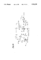
- FIG. 3 is a schematic of the controller circuit of the microterminal shown in FIG. 2.
- FIG. 4 is a schematic diagram of the connector used to connect the switches of the microterminal to its control circuit.
- FIG. 5 is a schematic diagram of the infrared receiver of the microterminal shown in FIG. 2.
- FIG. 6 is a schematic diagram of the infrared demodulator of the microterminal shown in FIG. 2.
- FIG. 7 is a schematic diagram of the infrared transmitter of the microterminal shown in FIG. 2.
- FIG. 8 is a schematic diagram of the auxiliary port which can be used to communicate data to the controller of the microterminal shown in FIG. 2.
- FIG. 9 is a schematic diagram of the auxiliary memory and timing circuit of the microterminal shown in FIG. 2.
- FIG. 10 is a schematic diagram of the circuit used by the controller of the microterminal to generate audible signals.
- FIG. 11 is a schematic diagram of the power processing circuit of the microterminal shown in FIG. 2.
- FIG. 12 is a schematic diagram of the circuit used to control the contrast of the LCD display of the microterminal shown in FIG. 2.
- FIG. 13 is a schematic diagram of the LCD display connection of the microterminal shown in FIG. 2.
- FIG. 14 is a schematic diagram of the control circuit for the infrared transceivers of the present invention.
- FIG. 15 is a schematic diagram of a memory module used in the infrared transceivers of the present invention.
- FIG. 16 is a schematic diagram of the auxiliary port which can be used to communicate data to the controller of the infrared transceiver.
- FIG. 17 is a schematic diagram of the infrared emitter driver of the infrared transceiver.
- FIG. 18 is a schematic diagram of the infrared emitter array of the infrared transceiver.
- FIG. 19 is a schematic diagram of the infrared detection circuit of the infrared transceiver.
- FIG. 20 is a schematic diagram of the infrared detection pre-amplifier of the infrared transceiver.
- FIG. 21 is a schematic diagram of the infrared detection gain and demodulator circuit of the infrared transceiver.
- FIG. 22 is a diagram of the visual status indicator of the infrared transceiver.
- FIG. 23 is a schematic diagram of the circuit used by the infrared transceiver to process inputs from and outputs to the system controller of the present invention.
- FIG. 24 is a schematic diagram of the noise suppression circuit of the infrared transceiver.
- FIG. 25 is a schematic diagram of the control circuit of the interface module of the system controller of the present invention.
- FIG. 26 is a schematic diagram of the power control circuit of this interface module.
- FIG. 27 is a schematic diagram of the driver circuit for the LED activity indicators of this interface module.
- FIG. 28 is a schematic diagram of the connector used to couple the interface module to the rack of the system controller.
- FIG. 29 is a schematic diagram of the control circuit of the Ethernet interface module of the present invention.
- FIG. 30 is a schematic diagram of the drivers and connector used to couple the Ethernet interface to the rack of the system controller.
- FIG. 31 is a schematic diagram of the memory module of the Ethernet interface.
- FIG. 32 is a schematic diagram of the voltage regulator of the Ethernet interface.
- FIG. 33 is a schematic diagram of the drivers for the Ten-Base-T connection and various LED indicators of the Ethernet interface.
- FIG. 34 is a schematic diagram of the connector used to run diagnostics on the Ethernet interface.
- FIG. 35 is a schematic diagram of a driver for the status LED of the Ethernet interface.
- FIG. 1 is intended to show the arrangement of various hardware components of a typical installation of the present invention.
- a local area network 1 is established using Ethernet Ten-Base-T wiring. Attached to the local area network is a file server 2, a CIM (computer integrated manufacturing) terminal 3, a number of client application computers 4, one or more computers 5 configured to control processing equipment within the factory, and a system controller 6. Wired to the system controller 6 can be one or more optical character readers 7, one or more bar code readers 8, and a plurality of infrared transceivers (IRTs) 9. In a typical arrangement, the IRTs 9 are mounted in the ceiling of the factory or on one of the processing tools 10.
- IRTs infrared transceivers
- the system also includes a plurality of transportable containers which, during manufacture, are moved to various points within the factory. Each of these containers is equipped with a microterminal 12 specifically designed and adapted for infrared communication with the IRTs 9 within the factory. Given this arrangement, messages can be sent through the system controller 6 and IRTs 9 to the microterminals 12 from the server 2, any of the client applications 4, or the CIM terminal 3 attached to the local area network 1.
- FIG. 2 shows the exterior of microterminal 12. As shown, it includes a liquid crystal display 20, four push buttons 22, 24, 26 and 28, a beeper 30, and a lens 32 for the microterminal's IR light generator and detector.
- the design of the microterminal 12 allows it to perform many different functions. Its primary purpose is to serve as a portable, wireless, electronic terminal, the use of which allows workers in the factory to communicate with the LAN 1.
- the microterminal 12 uses modulated infrared light as a communication medium and is capable of receiving and displaying text and graphic information from the LAN 1 on its display 20.
- the microterminal 12 is capable of transmitting information related to its identity and status as well as operator responses entered on one of four push button switches 22-28.
- the microterminal 12 is also capable of storing text messages and graphic images and to recall them to the display 20 on operator demand. To attract the operator's attention, the microterminal 12 can also generate audible signals using beeper 30. Still another important function of the microterminal 12 is its ability to provide location information to help operators locate, for example, a container to which the microterminal 12 is attached.
- the microterminal 12 includes a CMOS microcontroller 40, a 3.579545 MHZ internal oscillator 42 under resonator control for accurate timing and data generation, and a motion sensor 44.
- the CPU also has firmware to control all functions and operations of the microterminal.
- FIG. 4 shows a jack 46 to which the four membrane switches 22-28 are attached.
- Jack 46 provides inputs to the microterminal 40 through pins 15-18 of the microcontroller 40 (i.e., PB1-PB4) shown on the left-hand side of the microcontroller in FIG. 3.
- PB1-PB4 the microcontroller 40
- FIG. 5 shows the infrared receiver 50 of the microterminal. It includes three photo detectors 52, a transformer 54, and a differential amplifier 56 which compares the output of the transformer with a known value. Output from the infrared receiver is fed to an infrared demodulator 60 shown in FIG. 6. The output of the demodulator circuit is then fed into the microcontroller 40 via the microcontroller's input pin 12 (+RCV).
- the microterminal 12 must also be used to transmit infrared signals.
- the transmitter 70 receives instructions from the microcontroller 40 via the microcontroller's pin 11 (ENIR).
- ENIR the microcontroller's pin 11
- the ENIR signal from pin 11 opens or closes switch 72 to modulate the output of LEDs 74.
- an auxiliary port for example, an RS232 serial port
- This port is connected to the microcontroller 40 via pin 28 (port) on the microcontroller 40.
- the microterminal includes three other RAM memories 80, 82 and 84. These are shown in FIG. 9.
- Memory 80 is referred to as time base RAM because the information stored therein is principally used for timing and execution of the instructions contained in the firmware.
- Information is transmitted between RAM chip 80 and the microcontroller 40 via the microcontroller's pin 30 (RAM1).
- the auxiliary RAM chip 82 is provided to store messages to be displayed and the like.
- RAM chip 82 communicates with the microcontroller 40 via the microcontroller's pin 29 (RAM2).
- the primary function of RAM memory 84 is to store font information for display purposes. It communicates with the microcontroller 40 via the microcontroller's pins 37 (CK) and 40 (DT).
- the beeper 30 is also controlled by the microcontroller 40.
- Pin 14 (Beep) of the microcontroller 40 is used to send control signals to the beeper causing it to sound. See FIG. 10.
- the power processing circuit 90 includes a pair of battery connect wires 90 and 92 and is used to power the LCD display 20, the microcontroller 40, as well as the remaining components of the microterminal.
- the contrast of the LCD display 20 is controlled by the circuit 100 shown in FIG. 12.
- the display 20 is connected to the microcontroller 20, the LCD contrast control circuit 100 and the power processing circuit 90. This is all done through jack 120 shown in FIG. 13. More specifically, the jack 120 is connected to pins 2-9 (DB0-DB7), 24 (VDISP), 33 (DRST), 36 (R/W), 38 (STB) and 39 (D/I) of microcontroller 40. Pin 3 of jack 120 is connected to the output of LCD contrast control circuit 100 shown in FIG. 12 and power is provided to the display via output VLCD of the power processing circuit 90 shown in FIG. 11.
- the display 20 was specifically chosen to reduce energy consumption. Hence, it is a liquid crystal 32 row by 128 column display. It is capable of displaying 21 characters per line.
- the display 20 has its own volatile read/write memory and also has a non-volatile serial read/write memory to hold data necessary to translate character codes into display-ready font images. This display also holds some graphic images as well as a variety of text messages which can be displayed.
- the display 20 contains a voltage inverter system driven by the microcontroller 40 to generate negative voltage potentials required to activate the LCD pixels.
- the IR receiver 50 of the microterminal 20 uses high speed infrared technology to detect and decode 447 kilohertz modulated IR signals at 880 nanometer wavelengths.
- the conical acceptance angle of the IR receiver is 80° from vertical.
- the IR receiver is surrounded by a cover 32 that is 95% transparent to IR energy at 880 nanometer wavelengths. Given this configuration, the IR receiver has a range of approximately 20 feet.
- the microterminal's IR transmitter 70 is a current mode, high speed, high efficiency, 880 nanometer IR transmitter.
- the transmitter is pulse modulated at 447 kilohertz by serial data encoded in the pulse position modulation (PPM) format.
- PPM pulse position modulation
- the transmitter has an 80° radiation angle and generates light energy using three semi-conductor devices 74.
- the user input system of the microterminal includes four switches 22, 24, 26 and 28. Each of the four switches are momentary contact, conductive rubber push button switches. Each is able to signal the microterminal 20 to generate messages which are then sent to the IRTs 9 through the infrared transmitter 70 of the microterminal 12.
- the microterminal 12 provides an audible chirp through beeper 30 with each button press. This chirp is generated by the microterminal 40 and, thus, provides positive user feedback that the signal has been sent.
- the power management system (See FIG. 11) of the microcontroller 40 includes two lithium thionyl chloride batteries in an AA cell Form Factor. Each cell has the capacity of 2100 milliampere-hours at nominally 3.6 volts.
- the power management system includes circuit protection against a reversal as well as power filtering and power conditioning.
- the microcontroller 40 of the microterminal 12 is capable of monitoring battery status so that low battery conditions can be reported to both the display 20 and the factory's central control computer (file server) 2. While the batteries of the microterminal 12 are not rechargeable, they are replaceable.
- the microterminal 12 includes a unique timing system which is specifically designed to extend battery life.
- the timing system which will be described in further detail below, causes the main processing unit to enter a power-down sleep mode for extended periods of time.
- the timing system includes a 32,768 hertz ceramic resonator 86 (see FIG. 9) which activates the microcontroller 40 of the microterminal at pre-defined intervals for routine processing.
- the self-test subsystem of the microterminal performs basic memory and data checks on power up. It also uses the display 20 to report error conditions. If the display 20 is not operable, a series of beeps can be generated using beeper 30 to report errors. For example, the microterminal 12 will generate two beeps if the first RAM memory 80 is not responding. Three beeps are reported if the first RAM 80 is not returning correct data. If four or five beeps are generated, this is an indication that there is a problem with the second RAM memory 82. Four beeps means that the RAM is not responding at all. Five beeps means that the RAM is not returning correct data. Finally, six beeps indicates a failure in the font RAM 84.
- the operation of the microterminal 12 is controlled by firmware placed in the microterminal's microcontroller 40 at the time the microterminal 12 is manufactured. General parameters related to operation of the microterminal 12 will now be described.
- Each microterminal 12 is provided with a unique ID number that is stored in non-volatile memory.
- the ID number is used to uniquely identify the microterminal, to selectively direct data from the system controller 6 to the microterminal 12, to determine the microterminal's location, and is used by the system controller 6 to determine the source of data received from the microterminal.
- these identification numbers are 16 bit allowing 65,535 unique ID numbers to exist in a single system.
- the microterminals 12 also have a site code which is used to differentiate microterminals among 256 distinct sites or subsystems, providing 16 million unique microterminal designations.
- the location of the microterminals 12 can be effectively tracked because each room or distinct area within the factory is equipped with its own IRT 9.
- the IRTs 9 are designed to send out beacons which contain a unique ID number.
- the microterminals 12 use the IRT's ID number in the beacon to determine whether the microterminal 12 has been physically moved since it received the last beacon.
- the microterminal 12 determines that it has changed locations, it reports to the central control system that it has moved to a new location through an infrared transmission to the IRT 9. Reports by the microterminals 12 are continued in randomized fashion until the central control system acknowledges receipt of the location report.
- the maximum rate for the location reports is typically once every four seconds for each microterminal.
- the microterminal 12 has four modes of operation: a stand-by mode, an operate mode, a power saving mode and an extended sleep mode. The majority of the time, the microterminals 12 remain in the low power stand-by mode.
- the microterminals 12 are activated periodically to check their location and see if messages for the tag are being generated by the system controller 6.
- the microterminals 12 can be also be activated by actuation of a push button switch (22, 24, 26 or 28) by one of the workers in the factory or by motion sensor 44 if physical motion greater than 0.2 g occurs.
- a push button switch 22, 24, 26 or 28
- the microterminal 12 When the microterminal 12 enters the operate mode, the microcontroller 40 is awakened, and the display 20 and IR receiver 50 are powered. In this state, the microterminal 12 is ready to interact with the system controller 6 of the central control system. In the operate mode, a variety of things can occur. First, the microterminal 12 is able to receive messages for display. The tag is also able to display the memory contents as requested by the user. Finally, the microterminal 12 is able to generate transmission of user responses.
- a microterminal 12 When a microterminal 12 receives a message sent to it by the central control system, it looks for certain information embedded in the message. Embedded in the message, for example, is an instruction to display the message on the liquid crystal display 20 or store the message in display memory. Commands and the message can also activate the microterminal's beeper 30 or invoke the display of preprogramed textual or graphic messages stored in the display's non-volatile memory. When the microterminal 12 receives a system message, the microterminal issues a short response message which serves as an acknowledgment.
- All messages sent to the microterminal 12 include a sequence number which is returned as a validation of receipt.
- the sequence number is also used to prevent duplication.
- the central controller will continue to transmit messages through the system controller 6 and IRT 9 until an acknowledgment is returned by the microterminal 12. This greatly improves reliability of the data path to the microterminal 12.
- Messages received by the microterminal 12 from the central controller can also contain a control code which causes the microcontroller 12 to enter a "query" mode.
- a cursor flashes on the display 20 and buttons 22 and 24 on the microterminal 12 can be used to generate messages "yes" and "no".
- buttons 22 and 24 on the microterminal 12 can be used to generate messages "yes" and "no".
- a factory worker presses button 22 a corresponding "yes" message is sent by the microterminal 12 to the central controller until an acknowledgment is received.
- the microterminal 12 leaves the query mode so that the buttons 22, 24, 26 and 28 can be used to scroll the display 20. The user can use the buttons to scroll the display anytime that the microterminal 12 is not in the query mode.
- microterminal 12 when the microterminal 12 is in the stand-by mode, actuation of the one of the buttons 22, 24, 26 or 28 will cause the microterminal 12 to switch to the operate mode. Subsequent button presses will scroll the display. After a period of time without activity, the microterminal 12 again returns to the stand-by mode.
- the microterminal 12 In addition to the stand-by and operate modes, the microterminal 12 also has a power saving mode. The microterminal automatically enters this mode when no beacon message is observed by the microterminal 12 for 60 seconds. Initially, the microterminal will wait to look for a beacon every 5 seconds. Over time, this five second interval is increased incrementally to a maximum of 4.2 minutes. The microterminal 12 will revert to the stand-by or operate mode if there is physical motion of the microterminal, a button is pressed or, a beacon is received.
- microterminal 12 has an extended sleep mode. This mode is intended for use by microterminals that are being placed into storage. Microterminals 12 in this mode do not wake up or receive beacons. Only a press of button 22, 24, 26 or 28 will return the microterminal 12 to operation. This mode can only be invoked by a special infrared message issued to the microterminal by the central controller.
- each IRT 9 is a fixed element in communication with the portable microterminals 12.
- the IRTs 9 are used by the central controller to perform both tracking of and communications with the microterminals 12.
- the IRTs 9 have a small plastic and aluminum enclosure which is designed to be inserted into existing ceiling raceways in place of the section of the raceway cover.
- the IRTs 9 have a dual pivot system for aiming and can have either a flood or spot type configuration.
- FIG. 14 shows the microcontroller 200 of the IRT 9.
- the microcontroller 200 includes a 3.579545 MHZ internal oscillator 202 under resonator control. Attached to the microcontroller 200 using pins 2-4 (NC, SCL and SDA) is a non-volatile memory module 204 shown in FIG. 15.
- FIG. 16 show the auxiliary input jack and circuit 206 which is connected to the microcontroller 200 using pin 26 (AUX).
- the IRTs 9 each include a IR emitter driver 208 shown in FIG. 17 and a IR emitter array 209 shown in FIG. 18.
- the IR emitter driver 208 receives inputs via pin 13 (+IRDRV) from the microcontroller 200 and processes these inputs to control the four semiconductor devices 210 of the IR emitter array 209.
- Signals coming back to the IRT 9 from the microterminal 12 are detected by four sensors 212 shown in FIG. 19. Each of these sensors 212 is coupled to an IR detector pre-amplifier 214 shown in FIG. 20. The output of pre-amplifier 214 is provided to the circuit 216 shown in FIG. 21 which performs both detector gain and demodulation of the IR signal. The output of circuit 216 is provided to the microcontroller 200 via pin 12 (*RCV).
- each IRT 9 is provided with a pair of light emitting diodes--LEDs 218 and 220 shown in FIG. 22.
- the microcontroller 200 lights these LEDs to provide a visual indicator of the operations being performed by the IRT 9. Connection of the LEDs to the microcontroller 200 is through pins 24 (LED1) and 25 (LED2) of the microcontroller 200.
- FIG. 23 is present to show the manner in which the IRT 9 processes inputs from and outputs to the system controller 6.
- the circuit shown in FIG. 23 is connected to the microcontroller 200 via microcontroller pins 21 (TXD) and 22 (RXD).
- TXD microcontroller pins 21
- RXD RXD
- Two connectors 230 and 232 are provided. Each is a RJ-45 female connector. Two are provided so the IRTs 9 can be daisy chained together for ease of installation. From the foregoing it should now be clear that each IRT 9 can perform infrared data modulation and demodulation and participate in an infrared communications protocol to handle communications between the central control system and the microterminals 12 in the field of view.
- the IRTs 9 also provide buffering of data and data exchange on interconnecting wires through a collision-based protocol.
- the three basic functions of the IRTs 9 are to provide data reception and demodulation, data modulation and transmission, and wired reception and transmission of data with the local area network.
- data When data is transmitted by the microterminals 12, it is received and demodulated in accordance with the specific protocol by the IRTs 9.
- the IRTs also buffer the messages for transmission onto the wire data network and provide blanking periods and noise masking to discern legitimate signals from background noise. See FIG. 24.
- the IRTs 9 perform a number of tests on any transmission. For example, the IRT 9 performs a longitudinal cyclic redundancy check to validate data received or to reject a message when the test fails. It also performs an 8-bit fixed format test to validate or reject messages.
- the IRT also provides longitudinal byte count validation against a length embedded in each message.
- Still another function of the IRT is to buffer inbound IR data for transfer to the network, stripping the messages of unnecessary control and check bytes.
- LEDs 218 and 220 on the IRT 9 provide an indication of successful or failed data reception and the IRT is designed to provide protection from buffer overrun to prevent receiver overload.
- the microcontroller 200 of the IRT 9 can also be disabled when requested by the central control system.
- the IRTs perform similar functions with data sent to the microterminals 12. Specifically, it modulates and transmits the IR signals to the microterminals 12 and transmits specially formed beacon messages every four seconds. Every beacon messages begins within 0.001 seconds of a four second clock with a time base accuracy better than 200 parts per million. Beacon messages may optionally be accompanied by messages from the central control system to microterminals 12 in the stand-by mode. As beacon messages are transmitted, an LED indication of beacon transmission is provided and the IRT locks out its IR receiver system.
- the IRTs 9 are also capable of providing wired network data reception and transmission. Specifically, the IRTs perform serial data reception of wire data messages from the system controller 6. To provide message validation, the IRTs 9 test the overall message cyclic redundancy check code and test the overall message length against embedded message link values. The IRTs 9 also perform address validation on inbound messages to verify that they are either broadcast messages or intended for that specific IRT 9 by an embedded 16 bit address. The IRTs 9 are also capable of performing circular data buffering of inbound messages based upon type.
- the IRTs 9 are also capable of providing overrun-error messages to the system controller 6 in the event buffer capacity of the IRT 9 is exceeded. These messages include the sequence number of the discarded messages so that they can be retransmitted.
- the IRT 9 One very important function performed by the IRT 9 is transmission of messages received from the microterminals 12 and stored in the IRT's demodulator buffer to the central controller via the system controller 6 and the wired network.
- the system is capable of retransmission of the messages in the event of collision, discarding messages after 256 failed attempts and extinguishing the transmission indicator LED 218 when the message has successfully been sent.
- the IRT has a number of data stored in non-volatile memory 204. These include the IRT's symbolic name, priority code, category code as well as operating mode control information.
- the IRTs 9 have been discussed above. However, the IRTs also perform several special functions worthy of discussion.
- the IRTs have an "ON" chip independent timing device. The presence of this watchdog timing device ensures proper functionality and recovery from loss of main loop operation lasting more than 2.5 seconds.
- the IRTs are controlled through the use of interrupt programing to ensure timely processing of data transmitted and received via the wired network. This interrupt programing also ensures interleave of data modulation, data demodulation and serial network transactions.
- the IRT is capable of responding to a special IRT inquiry from the central control system.
- the response generated by the IRT includes a 12-character name string, a 16-bit IRT logical identifier, a code indicative of the firmware version, a code indicative of any firmware revisions, a firmware release date string, a single character IRT priority and single byte IRT category mode.
- the IRTs include the means to receive specifically coded IR messages and to respond for purposes of alignment and testing of the system.
- each IRT is provided with hardware protection against a firmware failure that could cause damaging currents to flow to the IRT emitters and IRT driver.
- the circuit is designed to provide the optimum current-control drive for the infrared emitters to accomplish emitted power of not less than 6 milliwatts per centimeter squared at a wave length of 880 nanometers. This yields a communications range of 18-24 feet with a 90° optical system and 42-50 feet with an 18° optical system.
- the IR receiver of the IRTs is designed to provide amplification of not less than 100 Dbv with a bandwidth of not less than 40:1.
- the receiver also provides protection against signal overload caused by nearby emitters so that there is no loss of reception. Shielding and filtering is provided to protect the electronics from electrical or magnetic interference and a narrow optical band width of not more than 300 nanometers is used to reject interference from ambient light.
- the receiver also provides high levels of rejection of low frequency (steady-state 60 hertz, and 120 hertz light components) to minimize or eliminate interference from daylight or commercial lighting systems.
- Power is supplied to the IRTs from one, two or three network pairs of the wires that connect the cabling that connects the IRT to the system controller. Operating powers not less than 8 volts and not more than 20 volts d.c. and not more than 0.025 amperes per IRT unit.
- the IRTs are specifically designed to tolerate reversal of one of more network power supply connectors or data pair connections.
- the IRTs are also provided with sufficient electrostatic discharge protection to prevent damage to other devices attached to the local area network during installation and repair.
- Inductor-capacitor (L/C) filtering of power and data lines is provided at the connectors to prevent the emission of board noise into the external lead wires and to prevent interference in the IRT from external noise.
- the system controller used to link the IRTs to the local area network is obviously a major component of the system.
- the system controller is essentially comprised of a standard rack frame, one or more IRT interface modules used to connect the IRTs to the controller, and one Ethernet interface module used to connect the system controller to the local area network.
- the structure of the IRT interface module in this preferred embodiment is shown in FIGS. 25 and 26.
- the module includes a CMOS microprocessor 300 with 2048 bytes of ROM program storage and 256 bytes of RAM memory.
- the module also includes a power control circuit shown in FIG. 26 which is electrically connected to microprocessor 300 via the microprocessor's pin 13 (SWPF).
- An activity LED driver circuit is also provided. This circuit is electrically connected to the circuit shown in FIG. 25 at the connection SWRX SNWTX. All the major components are electrically coupled to the edge connector shown in FIG. 28 so that the card can be plugged into the rack.
- FIGS. 25-28 show five LEDs. These lights serve to indicate the various functions being performed by the IRT interface module.
- LED 301 will glow green when more than 12.5 volts d.c. are on the IRT wire power pair.
- the LED 302 will glow red if a failure occurs on the IRT wire bus which prevents serial communication with the IRTs.
- LED 303 will glow green whenever serial data has been received and validated from the IRT wire bus. This LED is extinguished after data is delivered to the Ethernet interface module without error.
- LED 304 glows green whenever the IRT interface module is transmitting or attempting to transmit data on the bus.
- LED 305 glows green whenever the IRT interface module is receiving data from the IRT wire bus.
- FIGS. 29-35 are intended to show the construction of the Ethernet interface module.
- This module is used to bridge the data from the IRT interface module to the local area network.
- the Ethernet interface module includes an Intel 8051 microprocessor with 32,768 bytes of RAM, all of which has a lithium battery backup. One-half of this memory is for program storage and the other half of the memory is for working data storage.
- the Ethernet interface module also includes an RJ-11 maintenance jack 401 which provides an RS232 port connection.
- LED 402 is attached via the circuit shown in FIG. 5 to the microprocessor 401 using pin 27 (LED) on the microprocessor. This LED is illuminated when data has been received and validated from the IRT interface modules.
- LED 403 shown in FIG. 33 lights when the module transmits or attempts to transmit data on the Ethernet bus.
- LED 404 lights when the Ethernet interface module receives data from the Ethernet bus.
- LED 405 is illuminated when a good connection exists between the Ethernet module and the bus.
- jack 406 is provided so that the Ethernet interface module can be inserted and electrically connected to the rest of the components of the rack.
- the Ethernet interface module can be provided with a number of setable operating parameters. For example, an accumulation time limit can be set for the time allowed for inbound messages. Typically, this is set at 0.125 seconds. Likewise, the parameters related to retry can be set. For example, the number of retries can be set at five and the time to get a response message from the client computer on the network can be set for two seconds. Thus, if the response to the message is not received within two seconds, the message will be resent. Other items such as the IP address, the Ethernet address, the UPD port number and subnetwork math parameters can be set. This may be done directly via the Ethernet connection or also by using a tool to program the Ethernet interface module which is connected using the RJ-11 maintenance jack.
Abstract
Description
Claims (9)
Priority Applications (1)
| Application Number | Priority Date | Filing Date | Title |
|---|---|---|---|
| US08/522,692 US5742238A (en) | 1995-09-01 | 1995-09-01 | System for communication between a central controller and items in a factory using infrared light |
Applications Claiming Priority (1)
| Application Number | Priority Date | Filing Date | Title |
|---|---|---|---|
| US08/522,692 US5742238A (en) | 1995-09-01 | 1995-09-01 | System for communication between a central controller and items in a factory using infrared light |
Publications (1)
| Publication Number | Publication Date |
|---|---|
| US5742238A true US5742238A (en) | 1998-04-21 |
Family
ID=24081932
Family Applications (1)
| Application Number | Title | Priority Date | Filing Date |
|---|---|---|---|
| US08/522,692 Expired - Lifetime US5742238A (en) | 1995-09-01 | 1995-09-01 | System for communication between a central controller and items in a factory using infrared light |
Country Status (1)
| Country | Link |
|---|---|
| US (1) | US5742238A (en) |
Cited By (54)
| Publication number | Priority date | Publication date | Assignee | Title |
|---|---|---|---|---|
| US6047579A (en) * | 1998-04-17 | 2000-04-11 | The Minster Machine Company | RF tag attached to die assembly for use in press machine |
| WO2000026686A2 (en) * | 1998-10-29 | 2000-05-11 | Elpas Electro-Optic Systems Ltd. | System and method for infrared communication |
| US6138058A (en) * | 1998-01-06 | 2000-10-24 | Jenoptik Infab, Inc. | Method for electronically tracking containers to avoid misprocessing of contents |
| US6211790B1 (en) | 1999-05-19 | 2001-04-03 | Elpas North America, Inc. | Infant and parent matching and security system and method of matching infant and parent |
| WO2000071442A3 (en) * | 1999-05-21 | 2001-04-26 | Siemens Ag | Array for transporting goods |
| WO2001033749A1 (en) * | 1999-11-05 | 2001-05-10 | Elpas Electro-Optic Systems Ltd. | Method and system for transmitting short messages to a portable ir transceiver |
| US20010007818A1 (en) * | 2000-01-06 | 2001-07-12 | Yoshiaki Ichikawa | Fault monitoring method for commodity management radio communicating apparatus, storage medium for storing fault monitoring program for commodity management radio apparatus and fault monitoring program |
| EP1184805A1 (en) * | 2000-08-29 | 2002-03-06 | Motorola, Inc. | Electronic device for a wafer container, wafer manufacturing system, and method |
| US20020035524A1 (en) * | 2000-09-21 | 2002-03-21 | Martin Husslage | System and method for monitoring inventory amounts and locations |
| US6418352B1 (en) * | 1997-12-12 | 2002-07-09 | Brooks Automation Gmbh | Integrated material management module |
| US20020097141A1 (en) * | 1994-11-15 | 2002-07-25 | Micro Enhanced Technology, Inc. | Electronic access control device |
| US6452496B1 (en) | 1999-07-29 | 2002-09-17 | Micron Technology, Inc. | Radio frequency identification devices and a method of determining a communication range |
| US6459376B2 (en) | 1999-07-29 | 2002-10-01 | Micron Technology, Inc. | Radio frequency identification devices, remote communication devices, wireless communication systems, and methods of indicating operation |
| US6462661B2 (en) | 2000-11-20 | 2002-10-08 | Seagate Technology Llc | RF ID tag attachment to a disc drive |
| US20020167916A1 (en) * | 2001-05-14 | 2002-11-14 | Clapper Edward O. | Processor-based shopping cart |
| US20030019929A1 (en) * | 2001-05-31 | 2003-01-30 | Stewart Roger G. | Methods and apparatuses to identify devices |
| US20030067915A1 (en) * | 2001-10-04 | 2003-04-10 | Alcatel | Network nodes |
| US6547014B2 (en) | 2001-02-15 | 2003-04-15 | Ingersoll-Rand Company | Pneumatic tool housings having embedded electronic devices |
| US6568483B2 (en) | 2001-02-07 | 2003-05-27 | Ingersoll-Rand Company | Interchangeable pistol grip handles for pneumatic tools and seals therefor |
| US6594546B2 (en) * | 1999-10-29 | 2003-07-15 | Infineon Technologies Ag | Plant for processing wafers |
| US20030137403A1 (en) * | 2001-10-09 | 2003-07-24 | Carrender Curtis L. | Methods and apparatuses for identification |
| US6600899B1 (en) | 1999-11-05 | 2003-07-29 | Elpas Electro-Optic Systems Ltd. | Method and system for transmitting short messages to a portable IR transceiver |
| US6601164B1 (en) * | 1999-09-22 | 2003-07-29 | International Business Machines Corporation | Automatic identification of computer systems |
| US6618754B1 (en) * | 1995-10-23 | 2003-09-09 | Sun Microsystems, Inc. | System for transmission of embedded applications over a network |
| US6650225B2 (en) | 2000-12-11 | 2003-11-18 | Asap Automation, Llc | Wireless directed inventory system |
| US20040088497A1 (en) * | 2002-11-06 | 2004-05-06 | Deans Russell C. | Methods and apparatus for exchanging data using cyclic redundancy check codes |
| US20040207512A1 (en) * | 2000-12-11 | 2004-10-21 | Bastian William A. | Inventory system with image display |
| US20050083201A1 (en) * | 1999-07-29 | 2005-04-21 | Trosper Scott T. | Radio frequency identification devices, remote communication devices, identification systems, communication methods, and identification methods |
| US20050114326A1 (en) * | 2003-11-07 | 2005-05-26 | Smith John S. | Methods and apparatuses to identify devices |
| US20050140498A1 (en) * | 2000-12-11 | 2005-06-30 | Bastian William A.Ii | Inventory system with barcode display |
| EP1586011A2 (en) * | 2002-12-04 | 2005-10-19 | Dürr Somac GmbH | Method and device for tracking the position of tools and/or testing equipment |
| US20050263591A1 (en) * | 2003-08-09 | 2005-12-01 | Smith John S | Methods and apparatuses to identify devices |
| US20060087474A1 (en) * | 2004-10-27 | 2006-04-27 | Do Phuc K | Method and system for monitoring location based service emitter instructure |
| US20060279427A1 (en) * | 2005-03-29 | 2006-12-14 | Stryker Canadian Management, Inc. | Location detection system for a patient handling device |
| US20070096866A1 (en) * | 2001-12-27 | 2007-05-03 | Denison William D | Vending machines with field-programmable electronic locks |
| US20070096867A1 (en) * | 2001-12-27 | 2007-05-03 | Denison William D | Vending machines with field-programmable electronic locks |
| US20070210920A1 (en) * | 2006-03-09 | 2007-09-13 | George Panotopoulos | Identification (ID) system and method of operation thereof |
| US7284187B1 (en) * | 1997-05-30 | 2007-10-16 | Aol Llc, A Delaware Limited Liability Company | Encapsulated document and format system |
| US20070275750A1 (en) * | 2004-02-02 | 2007-11-29 | Nakagawa Laboratories, Inc. | Position Data Communication Device |
| US20080111675A1 (en) * | 2006-11-10 | 2008-05-15 | Micron Technology, Inc. | Tracking systems, passive RFIDs, methods of locating and identifying RFIDs, and methods of tracking items |
| US20080143546A1 (en) * | 2006-12-18 | 2008-06-19 | General Electric Company | Locating system and method |
| US20080186178A1 (en) * | 2007-02-07 | 2008-08-07 | Micron Technology, Inc. | RFIDS, interrogators, indication systems, methods of determining a bi-directional communication range of an interrogator, methods of activating an observable indicator, and methods of indicating bi-directional functionality of a radio connection |
| US20090051486A1 (en) * | 2001-12-27 | 2009-02-26 | Micro Enhanced Technologies, Inc | Electronic key control and management system for vending machines and the like |
| US20100229015A1 (en) * | 2009-03-05 | 2010-09-09 | Entropic Communications, Inc. | Method and Apparatus of Power Management |
| WO2011019333A1 (en) | 2009-08-09 | 2011-02-17 | Hewlett-Packard Development Company, L.P. | Illuminable indicator of electronic device being enabled based at least on user presence |
| CN102428012A (en) * | 2009-05-21 | 2012-04-25 | 罗格诺物流创新有限公司 | Shipping container vent cover for theft detection, theft prevention and logistics management and method for securing shipping container |
| CN102502133A (en) * | 2011-10-12 | 2012-06-20 | 四川科泰智能电子有限公司 | Safe intelligent detection device of satellite positioning container |
| US8278779B2 (en) | 2011-02-07 | 2012-10-02 | General Electric Company | System and method for providing redundant power to a device |
| US8643487B2 (en) | 2003-12-11 | 2014-02-04 | Triteq Lock And Security, Llc | Electronic security system for monitoring mechanical keys and other items |
| US9830424B2 (en) | 2013-09-18 | 2017-11-28 | Hill-Rom Services, Inc. | Bed/room/patient association systems and methods |
| US9937090B2 (en) | 2005-03-29 | 2018-04-10 | Stryker Corporation | Patient support apparatus communication systems |
| US10269202B2 (en) | 2001-12-27 | 2019-04-23 | Mobile Tech, Inc. | Intelligent key system |
| US10540872B2 (en) | 2016-04-15 | 2020-01-21 | Mobile Tech, Inc. | Gateway-based anti-theft security system and method |
| US11911325B2 (en) | 2019-02-26 | 2024-02-27 | Hill-Rom Services, Inc. | Bed interface for manual location |
Citations (39)
| Publication number | Priority date | Publication date | Assignee | Title |
|---|---|---|---|---|
| US3745569A (en) * | 1971-07-22 | 1973-07-10 | Raytheon Co | Remotely powered transponder |
| US3812328A (en) * | 1972-05-31 | 1974-05-21 | Pitney Bowes Inc | Credit card |
| US3852755A (en) * | 1971-07-22 | 1974-12-03 | Raytheon Co | Remotely powered transponder having a dipole antenna array |
| US4068232A (en) * | 1976-02-12 | 1978-01-10 | Fairchild Industries, Inc. | Passive encoding microwave transponder |
| US4570058A (en) * | 1983-10-03 | 1986-02-11 | At&T Technologies, Inc. | Method and apparatus for automatically handling and identifying semiconductor wafers |
| US4600630A (en) * | 1983-09-28 | 1986-07-15 | Rca Corporation | Method for making a protective coating on a machine-readable marking and the product thereof |
| US4611380A (en) * | 1982-12-28 | 1986-09-16 | Nissan Motor Company, Limited | Assembly line manufacturing control apparatus |
| US4636950A (en) * | 1982-09-30 | 1987-01-13 | Caswell Robert L | Inventory management system using transponders associated with specific products |
| US4642017A (en) * | 1982-09-30 | 1987-02-10 | Amca International Corporation | Automated in-process pipe storage and retrieval system |
| US4656463A (en) * | 1983-04-21 | 1987-04-07 | Intelli-Tech Corporation | LIMIS systems, devices and methods |
| US4670295A (en) * | 1983-09-28 | 1987-06-02 | Rca Corporation | Method for making a protective coating on a machine-readable marking |
| US4724427A (en) * | 1986-07-18 | 1988-02-09 | B. I. Incorporated | Transponder device |
| US4734698A (en) * | 1985-10-31 | 1988-03-29 | X-Cyte, Inc. | Passive interrogator label system having offset compensation and temperature compensation for a surface acoustic wave transponder |
| US4775786A (en) * | 1986-03-03 | 1988-10-04 | Daiken Kagaku Kogyo Kabushiki Kaisha | Bar code label |
| US4786907A (en) * | 1986-07-14 | 1988-11-22 | Amtech Corporation | Transponder useful in a system for identifying objects |
| US4814742A (en) * | 1985-04-04 | 1989-03-21 | Sekisui Jushi Kabushiki Kaisha | Inquiry system for detecting a selected object |
| US4827110A (en) * | 1987-06-11 | 1989-05-02 | Fluoroware, Inc. | Method and apparatus for monitoring the location of wafer disks |
| US4827395A (en) * | 1983-04-21 | 1989-05-02 | Intelli-Tech Corporation | Manufacturing monitoring and control systems |
| US4833306A (en) * | 1988-05-18 | 1989-05-23 | Fluoroware, Inc. | Bar code remote recognition system for process carriers of wafer disks |
| US4837568A (en) * | 1987-07-08 | 1989-06-06 | Snaper Alvin A | Remote access personnel identification and tracking system |
| US4843640A (en) * | 1986-04-24 | 1989-06-27 | Gte Valeron Corporation | Industrial identification transponder |
| US4857893A (en) * | 1986-07-18 | 1989-08-15 | Bi Inc. | Single chip transponder device |
| US4862160A (en) * | 1983-12-29 | 1989-08-29 | Revlon, Inc. | Item identification tag for rapid inventory data acquisition system |
| US4941201A (en) * | 1985-01-13 | 1990-07-10 | Abbott Laboratories | Electronic data storage and retrieval apparatus and method |
| US4962466A (en) * | 1987-03-27 | 1990-10-09 | Viscom Systems, Inc. | Electronic product information display system |
| US4990892A (en) * | 1989-08-07 | 1991-02-05 | Westcom, A Division Of Westside Communications Of Jacksonville, Inc. | Personnel locator system |
| US5005125A (en) * | 1986-02-28 | 1991-04-02 | Sensormatic Electronics Corporation | Surveillance, pricing and inventory system |
| US5097421A (en) * | 1984-12-24 | 1992-03-17 | Asyst Technologies, Inc. | Intelligent waxer carrier |
| US5119104A (en) * | 1990-05-04 | 1992-06-02 | Heller Alan C | Location system adapted for use in multipath environments |
| US5146207A (en) * | 1991-07-01 | 1992-09-08 | Bi, Incorporated | Secure field monitoring device for use in electronic house arrest monitoring system |
| US5153842A (en) * | 1990-02-05 | 1992-10-06 | Pitney Bowes Inc. | Integrated circuit package label and/or manifest system |
| US5204986A (en) * | 1988-02-25 | 1993-04-20 | Kabushiki Kaisha Toahiba | Battery powered radio devices having a battery saving function |
| US5262885A (en) * | 1989-04-18 | 1993-11-16 | U.S. Philips Corporation | Control circuit and data transmission device provided with such a circuit |
| US5266925A (en) * | 1991-09-30 | 1993-11-30 | Westinghouse Electric Corp. | Electronic identification tag interrogation method |
| US5276496A (en) * | 1992-10-30 | 1994-01-04 | Precision Tracking Fm, Inc. | Optical receiver for area location system |
| US5327115A (en) * | 1992-07-29 | 1994-07-05 | Remi Swierczek | Programmable document clip |
| US5339074A (en) * | 1991-09-13 | 1994-08-16 | Fluoroware, Inc. | Very low frequency tracking system |
| US5387993A (en) * | 1993-06-25 | 1995-02-07 | Precision Tracking Fm, Inc. | Method for receiving and transmitting optical data and control information to and from remotely located receivers and transmitters in an optical locator system |
| US5572195A (en) * | 1994-08-01 | 1996-11-05 | Precision Tracking Fm, Inc. | Sensory and control system for local area networks |
-
1995
- 1995-09-01 US US08/522,692 patent/US5742238A/en not_active Expired - Lifetime
Patent Citations (41)
| Publication number | Priority date | Publication date | Assignee | Title |
|---|---|---|---|---|
| US3852755A (en) * | 1971-07-22 | 1974-12-03 | Raytheon Co | Remotely powered transponder having a dipole antenna array |
| US3745569A (en) * | 1971-07-22 | 1973-07-10 | Raytheon Co | Remotely powered transponder |
| US3812328A (en) * | 1972-05-31 | 1974-05-21 | Pitney Bowes Inc | Credit card |
| US4068232A (en) * | 1976-02-12 | 1978-01-10 | Fairchild Industries, Inc. | Passive encoding microwave transponder |
| US4636950A (en) * | 1982-09-30 | 1987-01-13 | Caswell Robert L | Inventory management system using transponders associated with specific products |
| US4642017A (en) * | 1982-09-30 | 1987-02-10 | Amca International Corporation | Automated in-process pipe storage and retrieval system |
| US4611380A (en) * | 1982-12-28 | 1986-09-16 | Nissan Motor Company, Limited | Assembly line manufacturing control apparatus |
| US4827395A (en) * | 1983-04-21 | 1989-05-02 | Intelli-Tech Corporation | Manufacturing monitoring and control systems |
| US4656463A (en) * | 1983-04-21 | 1987-04-07 | Intelli-Tech Corporation | LIMIS systems, devices and methods |
| US4600630A (en) * | 1983-09-28 | 1986-07-15 | Rca Corporation | Method for making a protective coating on a machine-readable marking and the product thereof |
| US4670295A (en) * | 1983-09-28 | 1987-06-02 | Rca Corporation | Method for making a protective coating on a machine-readable marking |
| US4570058A (en) * | 1983-10-03 | 1986-02-11 | At&T Technologies, Inc. | Method and apparatus for automatically handling and identifying semiconductor wafers |
| US4862160A (en) * | 1983-12-29 | 1989-08-29 | Revlon, Inc. | Item identification tag for rapid inventory data acquisition system |
| US5097421A (en) * | 1984-12-24 | 1992-03-17 | Asyst Technologies, Inc. | Intelligent waxer carrier |
| US4941201A (en) * | 1985-01-13 | 1990-07-10 | Abbott Laboratories | Electronic data storage and retrieval apparatus and method |
| US4814742A (en) * | 1985-04-04 | 1989-03-21 | Sekisui Jushi Kabushiki Kaisha | Inquiry system for detecting a selected object |
| US4734698A (en) * | 1985-10-31 | 1988-03-29 | X-Cyte, Inc. | Passive interrogator label system having offset compensation and temperature compensation for a surface acoustic wave transponder |
| US5005125A (en) * | 1986-02-28 | 1991-04-02 | Sensormatic Electronics Corporation | Surveillance, pricing and inventory system |
| US4775786A (en) * | 1986-03-03 | 1988-10-04 | Daiken Kagaku Kogyo Kabushiki Kaisha | Bar code label |
| US4843640A (en) * | 1986-04-24 | 1989-06-27 | Gte Valeron Corporation | Industrial identification transponder |
| US4786907A (en) * | 1986-07-14 | 1988-11-22 | Amtech Corporation | Transponder useful in a system for identifying objects |
| US4857893A (en) * | 1986-07-18 | 1989-08-15 | Bi Inc. | Single chip transponder device |
| US4724427A (en) * | 1986-07-18 | 1988-02-09 | B. I. Incorporated | Transponder device |
| US4962466A (en) * | 1987-03-27 | 1990-10-09 | Viscom Systems, Inc. | Electronic product information display system |
| US4888473A (en) * | 1987-06-11 | 1989-12-19 | Fluoroware, Inc. | Wafer disk location monitoring system and tagged process carriers for use therewith |
| US4827110A (en) * | 1987-06-11 | 1989-05-02 | Fluoroware, Inc. | Method and apparatus for monitoring the location of wafer disks |
| US4888473B1 (en) * | 1987-06-11 | 1996-10-15 | Fluoroware Inc | Wafer disk location monitoring system and tagged process carrier for use therewith |
| US4837568A (en) * | 1987-07-08 | 1989-06-06 | Snaper Alvin A | Remote access personnel identification and tracking system |
| US5204986A (en) * | 1988-02-25 | 1993-04-20 | Kabushiki Kaisha Toahiba | Battery powered radio devices having a battery saving function |
| US4833306A (en) * | 1988-05-18 | 1989-05-23 | Fluoroware, Inc. | Bar code remote recognition system for process carriers of wafer disks |
| US5262885A (en) * | 1989-04-18 | 1993-11-16 | U.S. Philips Corporation | Control circuit and data transmission device provided with such a circuit |
| US4990892A (en) * | 1989-08-07 | 1991-02-05 | Westcom, A Division Of Westside Communications Of Jacksonville, Inc. | Personnel locator system |
| US5153842A (en) * | 1990-02-05 | 1992-10-06 | Pitney Bowes Inc. | Integrated circuit package label and/or manifest system |
| US5119104A (en) * | 1990-05-04 | 1992-06-02 | Heller Alan C | Location system adapted for use in multipath environments |
| US5146207A (en) * | 1991-07-01 | 1992-09-08 | Bi, Incorporated | Secure field monitoring device for use in electronic house arrest monitoring system |
| US5339074A (en) * | 1991-09-13 | 1994-08-16 | Fluoroware, Inc. | Very low frequency tracking system |
| US5266925A (en) * | 1991-09-30 | 1993-11-30 | Westinghouse Electric Corp. | Electronic identification tag interrogation method |
| US5327115A (en) * | 1992-07-29 | 1994-07-05 | Remi Swierczek | Programmable document clip |
| US5276496A (en) * | 1992-10-30 | 1994-01-04 | Precision Tracking Fm, Inc. | Optical receiver for area location system |
| US5387993A (en) * | 1993-06-25 | 1995-02-07 | Precision Tracking Fm, Inc. | Method for receiving and transmitting optical data and control information to and from remotely located receivers and transmitters in an optical locator system |
| US5572195A (en) * | 1994-08-01 | 1996-11-05 | Precision Tracking Fm, Inc. | Sensory and control system for local area networks |
Cited By (125)
| Publication number | Priority date | Publication date | Assignee | Title |
|---|---|---|---|---|
| US20050212656A1 (en) * | 1994-11-15 | 2005-09-29 | Micro Enhanced Technology, Inc. | Electronic access control device |
| US20050077998A2 (en) * | 1994-11-15 | 2005-04-14 | Micro Enhanced Techonology, Inc. | Electronic access control device |
| US7482907B2 (en) | 1994-11-15 | 2009-01-27 | Micro Enhanced Technology, Inc. | Electronic access control device |
| US7019615B2 (en) * | 1994-11-15 | 2006-03-28 | Micro Enhanced Technology, Inc. | Electronic access control device |
| US20040178885A1 (en) * | 1994-11-15 | 2004-09-16 | Denison William D. | Electronic access control device |
| US20040178884A1 (en) * | 1994-11-15 | 2004-09-16 | Denison William D. | Electronic access control device |
| US20040246098A1 (en) * | 1994-11-15 | 2004-12-09 | Denison William D. | Electronic access control device |
| US20060038657A1 (en) * | 1994-11-15 | 2006-02-23 | Denison William D | Electronic access control device |
| US20020097141A1 (en) * | 1994-11-15 | 2002-07-25 | Micro Enhanced Technology, Inc. | Electronic access control device |
| US8587405B2 (en) | 1994-11-15 | 2013-11-19 | O.S. Security | Electronic access control device |
| US7295100B2 (en) | 1994-11-15 | 2007-11-13 | Micro Enhanced Technology, Inc. | Electronic access control device |
| US7456725B2 (en) | 1994-11-15 | 2008-11-25 | Micro Enhanced Technology, Inc. | Electronic access control device utilizing a single microcomputer intergrated circuit |
| US7741952B2 (en) | 1994-11-15 | 2010-06-22 | Micro Enhanced Technology, Inc. | Electronic access control device |
| US20070164324A1 (en) * | 1994-11-15 | 2007-07-19 | Denison William D | Electronic access control device |
| US20040252016A1 (en) * | 1994-11-15 | 2004-12-16 | Micro Enhanced Technology, Inc. | Electronic acces control device |
| US6977576B2 (en) | 1994-11-15 | 2005-12-20 | Micro Enhanced Technology, Inc. | Electronic access control device |
| US7683758B2 (en) | 1994-11-15 | 2010-03-23 | Denison William D | Electronic access control device |
| US6618754B1 (en) * | 1995-10-23 | 2003-09-09 | Sun Microsystems, Inc. | System for transmission of embedded applications over a network |
| US7284187B1 (en) * | 1997-05-30 | 2007-10-16 | Aol Llc, A Delaware Limited Liability Company | Encapsulated document and format system |
| US6418352B1 (en) * | 1997-12-12 | 2002-07-09 | Brooks Automation Gmbh | Integrated material management module |
| US6138058A (en) * | 1998-01-06 | 2000-10-24 | Jenoptik Infab, Inc. | Method for electronically tracking containers to avoid misprocessing of contents |
| US6047579A (en) * | 1998-04-17 | 2000-04-11 | The Minster Machine Company | RF tag attached to die assembly for use in press machine |
| WO2000026686A3 (en) * | 1998-10-29 | 2000-09-08 | Elpas Electro Optic Systems Lt | System and method for infrared communication |
| WO2000026686A2 (en) * | 1998-10-29 | 2000-05-11 | Elpas Electro-Optic Systems Ltd. | System and method for infrared communication |
| US6211790B1 (en) | 1999-05-19 | 2001-04-03 | Elpas North America, Inc. | Infant and parent matching and security system and method of matching infant and parent |
| US6753781B2 (en) | 1999-05-19 | 2004-06-22 | Elpas North America, Inc. | Infant and parent matching and security system and method of matching infant and parent |
| WO2000071442A3 (en) * | 1999-05-21 | 2001-04-26 | Siemens Ag | Array for transporting goods |
| US8004407B2 (en) | 1999-07-29 | 2011-08-23 | Round Rock Research, Llc | Radio frequency identification devices, remote communication devices, identification systems, communication methods, and identification methods |
| US6459376B2 (en) | 1999-07-29 | 2002-10-01 | Micron Technology, Inc. | Radio frequency identification devices, remote communication devices, wireless communication systems, and methods of indicating operation |
| US20100013637A1 (en) * | 1999-07-29 | 2010-01-21 | Keystone Technology Solutions, Llc | Radio Frequency Identification Devices, Remote Communication Devices, Identification Systems, Communication Methods, and Identification Methods |
| US20070035395A1 (en) * | 1999-07-29 | 2007-02-15 | Trosper Scott T | Wireless communication devices, radio frequency identification devices, radio frequency identification device communication systems, wireless communication methods, and radio frequency identification device communication methods |
| US8253565B2 (en) | 1999-07-29 | 2012-08-28 | Round Rock Research, Llc | Radio frequency identification devices, remote communication devices, identification systems, communication methods, and identification methods |
| US6452496B1 (en) | 1999-07-29 | 2002-09-17 | Micron Technology, Inc. | Radio frequency identification devices and a method of determining a communication range |
| US7518515B2 (en) | 1999-07-29 | 2009-04-14 | Keystone Technology Solutions, Llc | Method and system for RFID communication |
| US6466130B2 (en) * | 1999-07-29 | 2002-10-15 | Micron Technology, Inc. | Wireless communication devices, wireless communication systems, communication methods, methods of forming radio frequency identification devices, methods of testing wireless communication operations, radio frequency identification devices, and methods of forming radio frequency identification devices |
| US7123148B2 (en) | 1999-07-29 | 2006-10-17 | Micron Technology, Inc. | Wireless communication devices, radio frequency identification devices, radio frequency identification device communication systems, wireless communication methods, and radio frequency identification device communication methods |
| US20050083201A1 (en) * | 1999-07-29 | 2005-04-21 | Trosper Scott T. | Radio frequency identification devices, remote communication devices, identification systems, communication methods, and identification methods |
| US8487766B2 (en) | 1999-07-29 | 2013-07-16 | Round Rock Research, LLP | Radio frequency identification devices, remote communication devices, identification systems, communication methods, and identification methods |
| US7071824B2 (en) | 1999-07-29 | 2006-07-04 | Micron Technology, Inc. | Radio frequency identification devices, remote communication devices, identification systems, communication methods, and identification methods |
| US6545605B2 (en) | 1999-07-29 | 2003-04-08 | Micron Technology, Inc. | Methods of determining a communications range of an interrogator of a wireless identification system and methods of verifying operation of a wireless identification system |
| US7737851B2 (en) | 1999-07-29 | 2010-06-15 | Round Rock Research, Llc | Radio frequency identification devices, remote communication devices, identification systems, communication methods, and identification methods |
| US6601164B1 (en) * | 1999-09-22 | 2003-07-29 | International Business Machines Corporation | Automatic identification of computer systems |
| US6594546B2 (en) * | 1999-10-29 | 2003-07-15 | Infineon Technologies Ag | Plant for processing wafers |
| WO2001033749A1 (en) * | 1999-11-05 | 2001-05-10 | Elpas Electro-Optic Systems Ltd. | Method and system for transmitting short messages to a portable ir transceiver |
| US6600899B1 (en) | 1999-11-05 | 2003-07-29 | Elpas Electro-Optic Systems Ltd. | Method and system for transmitting short messages to a portable IR transceiver |
| US20010007818A1 (en) * | 2000-01-06 | 2001-07-12 | Yoshiaki Ichikawa | Fault monitoring method for commodity management radio communicating apparatus, storage medium for storing fault monitoring program for commodity management radio apparatus and fault monitoring program |
| US7072648B2 (en) * | 2000-01-06 | 2006-07-04 | Nec Infrontia Corporation | Fault monitoring method for commodity management radio communicating apparatus, storage medium for storing fault monitoring program for commodity management radio apparatus and fault monitoring program |
| EP1184805A1 (en) * | 2000-08-29 | 2002-03-06 | Motorola, Inc. | Electronic device for a wafer container, wafer manufacturing system, and method |
| US20020035524A1 (en) * | 2000-09-21 | 2002-03-21 | Martin Husslage | System and method for monitoring inventory amounts and locations |
| US6462661B2 (en) | 2000-11-20 | 2002-10-08 | Seagate Technology Llc | RF ID tag attachment to a disc drive |
| US6650225B2 (en) | 2000-12-11 | 2003-11-18 | Asap Automation, Llc | Wireless directed inventory system |
| US20050140498A1 (en) * | 2000-12-11 | 2005-06-30 | Bastian William A.Ii | Inventory system with barcode display |
| US7084738B2 (en) | 2000-12-11 | 2006-08-01 | Asap Automation, Llc | Inventory system with image display |
| US20040207512A1 (en) * | 2000-12-11 | 2004-10-21 | Bastian William A. | Inventory system with image display |
| US7262685B2 (en) | 2000-12-11 | 2007-08-28 | Asap Automation, Llc | Inventory system with barcode display |
| US6568483B2 (en) | 2001-02-07 | 2003-05-27 | Ingersoll-Rand Company | Interchangeable pistol grip handles for pneumatic tools and seals therefor |
| US6547014B2 (en) | 2001-02-15 | 2003-04-15 | Ingersoll-Rand Company | Pneumatic tool housings having embedded electronic devices |
| US20020167916A1 (en) * | 2001-05-14 | 2002-11-14 | Clapper Edward O. | Processor-based shopping cart |
| US7262686B2 (en) | 2001-05-31 | 2007-08-28 | Alien Technology | Methods and apparatuses to identify devices |
| US6988667B2 (en) | 2001-05-31 | 2006-01-24 | Alien Technology Corporation | Methods and apparatuses to identify devices |
| US8284034B2 (en) | 2001-05-31 | 2012-10-09 | Alien Technology Corporation | Methods and apparatuses to identify devices |
| US20030019929A1 (en) * | 2001-05-31 | 2003-01-30 | Stewart Roger G. | Methods and apparatuses to identify devices |
| US20070262851A1 (en) * | 2001-05-31 | 2007-11-15 | Stewart Roger G | Methods and apparatuses to identify devices |
| US20050211787A1 (en) * | 2001-05-31 | 2005-09-29 | Stewart Roger G | Methods and apparatuses to identify devices |
| US7424020B2 (en) | 2001-10-04 | 2008-09-09 | Alcatel | Network nodes |
| US20030067915A1 (en) * | 2001-10-04 | 2003-04-10 | Alcatel | Network nodes |
| US7193504B2 (en) | 2001-10-09 | 2007-03-20 | Alien Technology Corporation | Methods and apparatuses for identification |
| US20070013484A1 (en) * | 2001-10-09 | 2007-01-18 | Curt Carrender | Methods and apparatuses for identification |
| US20030137403A1 (en) * | 2001-10-09 | 2003-07-24 | Carrender Curtis L. | Methods and apparatuses for identification |
| US8279047B2 (en) | 2001-10-09 | 2012-10-02 | Alien Technology Corporation | Methods and apparatus for anti-collision for radio frequency communication |
| US10984625B2 (en) | 2001-12-27 | 2021-04-20 | Mobile Tech, Inc. | Intelligent key system |
| US20070096867A1 (en) * | 2001-12-27 | 2007-05-03 | Denison William D | Vending machines with field-programmable electronic locks |
| US10269202B2 (en) | 2001-12-27 | 2019-04-23 | Mobile Tech, Inc. | Intelligent key system |
| US10453291B2 (en) | 2001-12-27 | 2019-10-22 | Mobile Tech, Inc. | Intelligent key system |
| US20090051486A1 (en) * | 2001-12-27 | 2009-02-26 | Micro Enhanced Technologies, Inc | Electronic key control and management system for vending machines and the like |
| US20070096866A1 (en) * | 2001-12-27 | 2007-05-03 | Denison William D | Vending machines with field-programmable electronic locks |
| US20040088497A1 (en) * | 2002-11-06 | 2004-05-06 | Deans Russell C. | Methods and apparatus for exchanging data using cyclic redundancy check codes |
| EP1586011A2 (en) * | 2002-12-04 | 2005-10-19 | Dürr Somac GmbH | Method and device for tracking the position of tools and/or testing equipment |
| US20050263591A1 (en) * | 2003-08-09 | 2005-12-01 | Smith John S | Methods and apparatuses to identify devices |
| US8742899B2 (en) | 2003-08-09 | 2014-06-03 | Alien Technology Corporation | Methods and apparatuses to identify devices |
| US8102244B2 (en) | 2003-08-09 | 2012-01-24 | Alien Technology Corporation | Methods and apparatuses to identify devices |
| US7562083B2 (en) | 2003-11-07 | 2009-07-14 | Alien Technology Corporation | RFID Huffman encoded commands |
| US20060117066A1 (en) * | 2003-11-07 | 2006-06-01 | Smith John S | RFID handshaking |
| US8768952B2 (en) | 2003-11-07 | 2014-07-01 | Alien Technology Corporation | Methods and apparatuses to identify devices |
| US7716160B2 (en) | 2003-11-07 | 2010-05-11 | Alien Technology Corporation | Methods and apparatuses to identify devices |
| US7716208B2 (en) | 2003-11-07 | 2010-05-11 | Alien Technology Corporation | RFID handshaking |
| US9483671B2 (en) | 2003-11-07 | 2016-11-01 | Ruizhang Technology Limited Company | Methods and apparatuses to identify devices |
| US20050114326A1 (en) * | 2003-11-07 | 2005-05-26 | Smith John S. | Methods and apparatuses to identify devices |
| US20100207739A1 (en) * | 2003-11-07 | 2010-08-19 | John Stephen Smith | Methods and apparatuses to identify devices |
| US20060143163A1 (en) * | 2003-11-07 | 2006-06-29 | Smith John S | RFID huffman encoded commands |
| US8643487B2 (en) | 2003-12-11 | 2014-02-04 | Triteq Lock And Security, Llc | Electronic security system for monitoring mechanical keys and other items |
| US20070275750A1 (en) * | 2004-02-02 | 2007-11-29 | Nakagawa Laboratories, Inc. | Position Data Communication Device |
| US7283093B2 (en) | 2004-10-27 | 2007-10-16 | International Business Machines Corporation | Method and system for monitoring location based service emitter infrastructure |
| US20060087474A1 (en) * | 2004-10-27 | 2006-04-27 | Do Phuc K | Method and system for monitoring location based service emitter instructure |
| US8319633B2 (en) | 2005-03-29 | 2012-11-27 | David Terrance Becker | Location detection system for a patient handling device |
| US20060279427A1 (en) * | 2005-03-29 | 2006-12-14 | Stryker Canadian Management, Inc. | Location detection system for a patient handling device |
| US8102254B2 (en) * | 2005-03-29 | 2012-01-24 | Stryker Canadian Management, Inc. | Location detection system for a patient handling device |
| US9937090B2 (en) | 2005-03-29 | 2018-04-10 | Stryker Corporation | Patient support apparatus communication systems |
| US8674826B2 (en) | 2005-03-29 | 2014-03-18 | Stryker Corporation | Location detection system for a device |
| US20100079304A1 (en) * | 2005-03-29 | 2010-04-01 | Stryker Canadian Management, Inc. | Location detection system for a patient handling device |
| US8461982B2 (en) | 2005-03-29 | 2013-06-11 | Stryker Corporation | Communication system for patient handling devices |
| US7598853B2 (en) * | 2005-03-29 | 2009-10-06 | Stryker Canadian Management, Inc. | Location detection system for a patient handling device |
| US7446658B2 (en) * | 2006-03-09 | 2008-11-04 | Avago Technologies General Ip (Singapore) Pte. Ltd. | Identification (ID) system and method of operation thereof |
| US20070210920A1 (en) * | 2006-03-09 | 2007-09-13 | George Panotopoulos | Identification (ID) system and method of operation thereof |
| US20110084808A1 (en) * | 2006-11-10 | 2011-04-14 | Round Rock Research, Llc | Tracking systems, methods of locating and identifying rfids, and methods of tracking items |
| US7855643B2 (en) | 2006-11-10 | 2010-12-21 | Round Rock Research, Llc | Tracking systems, passive RFIDs, methods of locating and identifying RFIDs, and methods of tracking items |
| US20080111675A1 (en) * | 2006-11-10 | 2008-05-15 | Micron Technology, Inc. | Tracking systems, passive RFIDs, methods of locating and identifying RFIDs, and methods of tracking items |
| US20080143546A1 (en) * | 2006-12-18 | 2008-06-19 | General Electric Company | Locating system and method |
| US20080186178A1 (en) * | 2007-02-07 | 2008-08-07 | Micron Technology, Inc. | RFIDS, interrogators, indication systems, methods of determining a bi-directional communication range of an interrogator, methods of activating an observable indicator, and methods of indicating bi-directional functionality of a radio connection |
| US20100229015A1 (en) * | 2009-03-05 | 2010-09-09 | Entropic Communications, Inc. | Method and Apparatus of Power Management |
| US8522061B2 (en) * | 2009-03-05 | 2013-08-27 | Entropic Communications, Inc. | Method and apparatus of power management of a node in home entertainment network by shifting from a normal state into either a first low power state based on the traffic at the node or a second low power state upon receipt of a message granting a request for the second low power state at the node |
| CN102428012B (en) * | 2009-05-21 | 2015-09-09 | 罗格诺物流创新有限公司 | Steal for detecing, the antitheft and shipping container ventilator cap of logistics management and the method for the protection of shipping container |
| CN102428012A (en) * | 2009-05-21 | 2012-04-25 | 罗格诺物流创新有限公司 | Shipping container vent cover for theft detection, theft prevention and logistics management and method for securing shipping container |
| WO2011019333A1 (en) | 2009-08-09 | 2011-02-17 | Hewlett-Packard Development Company, L.P. | Illuminable indicator of electronic device being enabled based at least on user presence |
| EP2462581A4 (en) * | 2009-08-09 | 2013-02-06 | Hewlett Packard Development Co | Illuminable indicator of electronic device being enabled based at least on user presence |
| EP2462581A1 (en) * | 2009-08-09 | 2012-06-13 | Hewlett-Packard Development Company, L.P. | Illuminable indicator of electronic device being enabled based at least on user presence |
| US8692683B2 (en) | 2009-08-09 | 2014-04-08 | Hewlett-Packard Development Company, L.P. | Illuminable indicator of electronic device being enabled based at least on user presence |
| US8278779B2 (en) | 2011-02-07 | 2012-10-02 | General Electric Company | System and method for providing redundant power to a device |
| CN102502133A (en) * | 2011-10-12 | 2012-06-20 | 四川科泰智能电子有限公司 | Safe intelligent detection device of satellite positioning container |
| US9830424B2 (en) | 2013-09-18 | 2017-11-28 | Hill-Rom Services, Inc. | Bed/room/patient association systems and methods |
| US11011267B2 (en) | 2013-09-18 | 2021-05-18 | Hill-Rom Services, Inc. | Bed/room/patient association systems and methods |
| US10540872B2 (en) | 2016-04-15 | 2020-01-21 | Mobile Tech, Inc. | Gateway-based anti-theft security system and method |
| US10776473B2 (en) | 2016-04-15 | 2020-09-15 | Mobile Tech, Inc. | Authorization control for an anti-theft security system |
| US11315398B2 (en) | 2016-04-15 | 2022-04-26 | Mobile Tech, Inc. | Gateway-based anti-theft security system and method |
| US11911325B2 (en) | 2019-02-26 | 2024-02-27 | Hill-Rom Services, Inc. | Bed interface for manual location |
Similar Documents
| Publication | Publication Date | Title |
|---|---|---|
| US5742238A (en) | System for communication between a central controller and items in a factory using infrared light | |
| US6138058A (en) | Method for electronically tracking containers to avoid misprocessing of contents | |
| CA2107610C (en) | Personnel and equipment locator system | |
| US5594786A (en) | Patient care and communication system | |
| US6958706B2 (en) | Patient care and communication system | |
| KR960014830B1 (en) | Very low frequency tracking system | |
| US5627524A (en) | Infrared locator system | |
| US5659761A (en) | Data recognition apparatus and portable data reader having power management system | |
| AU663770B2 (en) | Tracking and/or identification system | |
| US7525432B2 (en) | Methods, identification tags and computer program products for automated location and monitoring of mobile devices | |
| US7372365B2 (en) | Methods, systems and computer program products for automated location and monitoring of mobile device | |
| JPH03282581A (en) | Price indicating system and method related to said system | |
| KR100259984B1 (en) | Apparatus for checking and monitoring of driving condition of fan fillter unit | |
| JPH02193091A (en) | Wireless response device | |
| US20050088305A1 (en) | Identification apparatus | |
| US20020115341A1 (en) | Computer controlled order filling system | |
| US6917723B1 (en) | Optical data reader with control mechanism implemented behind the window | |
| EP0962787B1 (en) | Method of verifying an extension area sensor controller, master controller of area sensors, and cover to be used when no slave controller is added | |
| KR102185685B1 (en) | Light emitting diode module system with self-check function | |
| CN218383067U (en) | Assembly line electrostatic protection detection circuitry | |
| CN211293299U (en) | Infrared detection circuit | |
| JPH021672Y2 (en) | ||
| JP3126370B2 (en) | Terminal for remote control | |
| CN210091326U (en) | Anti-false-entry alarm device and system | |
| JP3261170B2 (en) | Control terminal for remote monitoring and control system |
Legal Events
| Date | Code | Title | Description |
|---|---|---|---|
| AS | Assignment |
Owner name: EMTRAK, INC., MINNESOTA Free format text: ASSIGNMENT OF ASSIGNORS INTEREST;ASSIGNOR:FOX, CHRISTOPHER WAYNE;REEL/FRAME:007667/0233 Effective date: 19950822 |
|
| STCF | Information on status: patent grant |
Free format text: PATENTED CASE |
|
| AS | Assignment |
Owner name: BROOKS AUTOMATION GMBH, GERMANY Free format text: ASSIGNMENT OF ASSIGNORS INTEREST;ASSIGNOR:JENOPTIK, AG;REEL/FRAME:010437/0486 Effective date: 19990930 |
|
| FEPP | Fee payment procedure |
Free format text: PAYOR NUMBER ASSIGNED (ORIGINAL EVENT CODE: ASPN); ENTITY STATUS OF PATENT OWNER: LARGE ENTITY |
|
| FPAY | Fee payment |
Year of fee payment: 4 |
|
| FPAY | Fee payment |
Year of fee payment: 8 |
|
| FPAY | Fee payment |
Year of fee payment: 12 |
|
| SULP | Surcharge for late payment |
Year of fee payment: 11 |
|
| FEPP | Fee payment procedure |
Free format text: PAYOR NUMBER ASSIGNED (ORIGINAL EVENT CODE: ASPN); ENTITY STATUS OF PATENT OWNER: LARGE ENTITY Free format text: PAYER NUMBER DE-ASSIGNED (ORIGINAL EVENT CODE: RMPN); ENTITY STATUS OF PATENT OWNER: LARGE ENTITY |