US5738825A - Optical biosensor matrix - Google Patents
Optical biosensor matrix Download PDFInfo
- Publication number
- US5738825A US5738825A US08/854,586 US85458697A US5738825A US 5738825 A US5738825 A US 5738825A US 85458697 A US85458697 A US 85458697A US 5738825 A US5738825 A US 5738825A
- Authority
- US
- United States
- Prior art keywords
- plate
- arrangement
- waveguiding film
- base plate
- distinct
- Prior art date
- Legal status (The legal status is an assumption and is not a legal conclusion. Google has not performed a legal analysis and makes no representation as to the accuracy of the status listed.)
- Expired - Lifetime
Links
Images


Classifications
-
- G—PHYSICS
- G01—MEASURING; TESTING
- G01N—INVESTIGATING OR ANALYSING MATERIALS BY DETERMINING THEIR CHEMICAL OR PHYSICAL PROPERTIES
- G01N21/00—Investigating or analysing materials by the use of optical means, i.e. using sub-millimetre waves, infrared, visible or ultraviolet light
- G01N21/17—Systems in which incident light is modified in accordance with the properties of the material investigated
- G01N21/25—Colour; Spectral properties, i.e. comparison of effect of material on the light at two or more different wavelengths or wavelength bands
- G01N21/251—Colorimeters; Construction thereof
- G01N21/253—Colorimeters; Construction thereof for batch operation, i.e. multisample apparatus
-
- B—PERFORMING OPERATIONS; TRANSPORTING
- B01—PHYSICAL OR CHEMICAL PROCESSES OR APPARATUS IN GENERAL
- B01L—CHEMICAL OR PHYSICAL LABORATORY APPARATUS FOR GENERAL USE
- B01L3/00—Containers or dishes for laboratory use, e.g. laboratory glassware; Droppers
- B01L3/50—Containers for the purpose of retaining a material to be analysed, e.g. test tubes
- B01L3/508—Containers for the purpose of retaining a material to be analysed, e.g. test tubes rigid containers not provided for above
- B01L3/5085—Containers for the purpose of retaining a material to be analysed, e.g. test tubes rigid containers not provided for above for multiple samples, e.g. microtitration plates
-
- G—PHYSICS
- G01—MEASURING; TESTING
- G01N—INVESTIGATING OR ANALYSING MATERIALS BY DETERMINING THEIR CHEMICAL OR PHYSICAL PROPERTIES
- G01N21/00—Investigating or analysing materials by the use of optical means, i.e. using sub-millimetre waves, infrared, visible or ultraviolet light
- G01N21/75—Systems in which material is subjected to a chemical reaction, the progress or the result of the reaction being investigated
- G01N21/77—Systems in which material is subjected to a chemical reaction, the progress or the result of the reaction being investigated by observing the effect on a chemical indicator
- G01N21/7703—Systems in which material is subjected to a chemical reaction, the progress or the result of the reaction being investigated by observing the effect on a chemical indicator using reagent-clad optical fibres or optical waveguides
- G01N21/774—Systems in which material is subjected to a chemical reaction, the progress or the result of the reaction being investigated by observing the effect on a chemical indicator using reagent-clad optical fibres or optical waveguides the reagent being on a grating or periodic structure
- G01N21/7743—Systems in which material is subjected to a chemical reaction, the progress or the result of the reaction being investigated by observing the effect on a chemical indicator using reagent-clad optical fibres or optical waveguides the reagent being on a grating or periodic structure the reagent-coated grating coupling light in or out of the waveguide
-
- B—PERFORMING OPERATIONS; TRANSPORTING
- B01—PHYSICAL OR CHEMICAL PROCESSES OR APPARATUS IN GENERAL
- B01L—CHEMICAL OR PHYSICAL LABORATORY APPARATUS FOR GENERAL USE
- B01L2300/00—Additional constructional details
- B01L2300/06—Auxiliary integrated devices, integrated components
- B01L2300/0627—Sensor or part of a sensor is integrated
- B01L2300/0654—Lenses; Optical fibres
-
- G—PHYSICS
- G01—MEASURING; TESTING
- G01N—INVESTIGATING OR ANALYSING MATERIALS BY DETERMINING THEIR CHEMICAL OR PHYSICAL PROPERTIES
- G01N21/00—Investigating or analysing materials by the use of optical means, i.e. using sub-millimetre waves, infrared, visible or ultraviolet light
- G01N21/17—Systems in which incident light is modified in accordance with the properties of the material investigated
- G01N21/47—Scattering, i.e. diffuse reflection
- G01N21/4788—Diffraction
-
- G—PHYSICS
- G01—MEASURING; TESTING
- G01N—INVESTIGATING OR ANALYSING MATERIALS BY DETERMINING THEIR CHEMICAL OR PHYSICAL PROPERTIES
- G01N2201/00—Features of devices classified in G01N21/00
- G01N2201/04—Batch operation; multisample devices
- G01N2201/0446—Multicell plate, sequential
Definitions
- This invention relates to the field of optical biosensors and the application of optical biosensors to biochemical analysis, particularly in combination with standard biochemical analysis techniques and equipment to permit automated analysis.
- Optical biosensors are devices which make use of the refractive and coupling properties of light to detect the presence of substances on a surface.
- Usually integrated optical biosensors have a waveguiding film, of a certain refractive index, which forms the surface which the sample of the substance contacts.
- a base sheet which has a lower refractive index than the waveguiding film, contacts the waveguiding film.
- a grating coupler or prism coupler is then positioned to cooperate with the base sheet to incouple light that is shone on the base sheet through the coupler. Monochromatic light is then shone on the base sheet through the coupler and the in- or out-coupled light monitored.
- Changes in the refractive index of the waveguiding film caused by molecules binding to it can be detected by observing changes in the angle of the emitted, out-coupled light.
- the waveguiding film can be coated with a complementary substance which specifically binds to the first substance.
- This biosensor comprises a base sheet joined to a waveguiding film; the surfaces of the sheet and film that join together being formed into a grating coupler or Bragg coupler.
- This grating coupler can be a unidiffractive or multidiffractive structure.
- the refractive index of the waveguiding film is higher than that of the base sheet.
- a chemo-sensitive substance is coated on the waveguiding film in an area of the waveguiding film that contacts the sample.
- a laser is used to direct monochromatic light towards the grating coupler at a selected angle of incidence.
- the position of the laser or of the grating coupler is then altered to change the angle of incidence until light is incoupled in the waveguiding film. Any change in the effective refractive index caused by molecules binding to the waveguiding film, disturbs the incoupling condition and the angle of incidence must be changed to correct for this. Hence changes in the angle of incidence (and this correlates directly to the position of the laser with respect to the grating coupler) required to maintain the incoupled light are monitored. These changes in the angle of incidence are then correlated to changes in the amount of molecules binding to the surface of the chemo-sensitive substance.
- this biosensor provides an extremely convenient means for detecting the presence and the amount of a substance in a sample.
- a drawback of the system is that the laser or grating coupler must be continually moved.
- a further optical biosensor is disclosed in WO 93/01487 and this optical biosensor permits the encoupled light to be monitored without the use of moving parts.
- This biosensor relies on the use of a fan-shaped, monochromatic light field which may be coupled in and out of the waveguiding structure.
- the outcoupled light field can be focussed to a point and the position of the point determined. Movement in the position of the point indicates changes in the effective refractive index of the waveguiding structure.
- Optical biosensors provide a very convenient means of detecting the presence of substances without the use expensive reagents and labelling techniques.
- optical biosensors can only be used to test single samples which must be placed in special detection cells.
- the laboratory technician must transport a sample to the optical biosenor, load it into the biosensor, and monitor it. Afterwards the biosensor must be cleaned. This severely limits the application of optical biosensors.
- this invention provides a detection cell for use as a component of an optical biosenor; the detection cell comprising a transparent base plate and a sample plate on the base plate; the sample plate having a matrix of wells extending through it to each receive a sample, and the base plate including a waveguiding film and a diffraction grating means to incouple an incident light field into the waveguiding film beneath a well to generate a diffracted light field to enable the detection of a change in the effective refractive index of the waveguiding film.
- the detection cell is of the same size and contains the same number of wells as a microtitre plate.
- microtitre plates contain 6, 24 or 96 wells but the number of wells can vary as desired. Therefore the detection cell provides the significant advantage that it can be used in conjunction with standard fluid-handling systems existent in analytical laboratories.
- the fluid handling systems can be used to clean the detection cell, and pipette samples into the detection cell, and move the detection cell from one position to the other.
- the optical biosensor of which the detection cell is a component, can then be used to analyse the contents of each well. Plainly the detection cell need not have a standard number of wells, any number of wells can be used.
- the base plate may be formed of a base sheet that is covered by the waveguiding film that has a higher refractive index than the base sheet.
- the diffraction grating means may be formed in the base sheet, between the base sheet and the waveguiding film, or in the waveguiding film. Preferably the diffraction grating means is formed in the interface between the waveguiding film and the base sheet.
- the base plate may be releasibly fixed to the sample plate so that it can be detached from the sample plate and replaced.
- a separate diffraction grating means may be provided beneath each well or a single diffraction grating means, that extends over substantially the entire base plate, may be provided.
- the waveguiding film is made of metal-oxide based materials such as Ta 2 O 5 , TiO 2 , TiO 2 --SiO 2 , HfO 2 , ZrO 2 , Al 2 O 3 , Si 3 N 4 , HfON, SiON, scandium oxide or mixtures thereof.
- metal-oxide based materials such as Ta 2 O 5 , TiO 2 , TiO 2 --SiO 2 , HfO 2 , ZrO 2 , Al 2 O 3 , Si 3 N 4 , HfON, SiON, scandium oxide or mixtures thereof.
- suitable silicon nitrides or oxynitrides for example HfO x N y
- especially suited materials are Ta 2 O 5 , HfO 2 , Si 3 N 4 , ZrO 2 , Al 2 O 3 medium oxide, or a mixture of SiO 2 and TiO 2 or one of the oxinitrides HfON or SiON, especially TiO 2 .
- the waveguiding film has a refractive index in the range 1.6 to 2.5.
- the thickness of the waveguiding film may be varied over the range 20 to 1000 nm, preferably 30 to 500 nm.
- the grating coupler preferably has a line density of 1000 to 3000 lines per mm, for example 1200 to 2400 lines per mm.
- the base sheet is preferably made of glass or plastics (polycarbonates) and preferably has a refractive index in the range 1.3 to 1.7, for example 1.4 to 1.6.
- the free surface of the waveguiding film is coated with a coupling layer that permits selective coupling of a specific substance in a well to the coupling layer.
- the coupling layer may be such that a reaction between it and the specific substance occurs resulting in a covalent bond or may rely on some other form of selective coupling such as antibody/antigen binding.
- the waveguiding film need not have a coupling layer if physical absorption, for example, of the specific substance to it provides sufficient selectivity.
- this invention provides an analytical system comprising a detection cell as defined above and a reading unit that comprises (i) at least one light source to generate and direct at least one incident light field onto the diffraction grating means beneath a well of the detection cell to provide mode excitation in the waveguiding film; (ii) at least one focusing means to focus the light field diffracted out of the waveguiding film beneath the well; and (iii) at least one position sensitive detector to monitor the position of the focussed light field.
- the incident light field is generated by a laser.
- more than one incident light field is provided; a light field being provided for each column of the matrix of the detection cell. If more than one light field is provided, they may be generated by providing (i) more than one light source, (ii) by splitting the field of a single light source, or (iii) by expanding a light field.
- more than one light detector may be provided; one light detector for each light field.
- the analytical system may also comprise a transport means to transport the detection cell, from a filling station in which the wells of the detection cell are filled, to a position to enable cooperation with the reading unit.
- the transport means may include position locking means so that the detection cell may be locked into exactly the same position with respect to the reading unit on each occasion that it is desired.
- the outcoupled light field alternatively may be scanned whilst the detection cell is moving with respect to the reading unit.
- this invention provides a method for the automated analysis of samples using an optical biosensor, the method comprising filling the wells of a detection cell as defined above with a carrier fluid; transporting the detection cell to a position to cooperate with a reading unit as defined above; monitoring the out-coupled light from each well and recording it to provide a reference; transporting the detection cell to a pipetting station and pipetting a sample into each well; transporting the detection cell back to the reading unit and directing light onto the diffraction grating means in the detection cell; monitoring the out-coupled light from each well; and comparing the results obtained to the reference.
- this invention provides a method for measuring the kinetics of a change in a sample, the method comprising filling the wells of a detection cell as defined above with a sample; transporting the detection cell to a position to enable cooperation with the reading unit as defined above; and monitoring repeatedly at discrete intervals the different diffracted light fields from each well; the time of each discrete interval for any cell being less than the time required for the change.
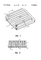
- FIG. 1 is a perspective view of a detection plate
- FIG. 2 is a cross-section on 2--2 of FIG. 1;
- FIG. 3 is an expanded view of area 3 of FIG. 2;
- FIG. 4 is a schematic illustration of a biosensor system including a detection cell and a reading unit
- FIGS. 5(a) to 5(h) illustrate schematically several configurations for the diffraction grating means beneath a well
- FIGS. 6(a) and 6(b) illustrate, schematically, configurations in which the absolute outcoupling angle may be determined.
- FIGS. 7(a) to 7(g) illustrate schematically several configurations for the diffraction grating means.
- the detection cell 2 is similar in shape and appearance to a standard microtitre plate (in this case, a 96 well plate).
- the detection cell 2 is formed of a sample plate 4 which is rectangular in plan and which has ninety-six wells 6 extending through it; from its upper surface to its lower surface.
- the wells 6 are arranged in a matrix of eight columns and twelve rows, each row being spaced an equal distance from its neighbors and each column being spaced an equal distance from its neighbours.
- a base sheet 8 is affixed to the lower surface of the sample plate 4 and seals off the bottom of the wells 6.
- the base sheet 8 is preferably releasibly attached to the sample plate 4 so that it can be removed from the sample plate 4. This enables the base sheet 8 to be better washed or treated, or to be replaced when necessary.
- the base plate consisting of base sheet 8 and waveguiding film 12 can also be irreversibly attached to the sample plate 4. This is attained for instance when the base plate and the sample plate 4 are ultrasonically welded together. Ultrasonic welding is possible although the waveguiding film 12 is not made up of a plastic material.
- the base sheet 8 is made of a suitable transparent material such as glass or plastics (for example, polycarbonates), and contains a diffraction grating 10 beneath each well 6. As is best illustrated in FIG. 3, the diffraction grating 10 is formed by a serrated interface between-the base sheet 8 and a waveguiding film 12.
- the waveguiding film 12 has a refractive index of about 2.43 (which is higher than that of the base sheet 8) and is made of TiO 2 .
- the thickness of the waveguiding film 12 is in the region of 20 to 500 nm.
- the density of the gratings of the diffraction grating 10 is conveniently about 1000 to 3000 lines per mm.
- the diffraction grating 10 may be manufactured by lithography, embossing techniques or injection moulding.
- each well 6 may be covered with a coupling layer 14 to which only specific substances will selectively bind.
- the coupling layer 14 can be made of an antibody which has been raised against a specific antigen. Therefore, if this antigen is present in the sample in the well 6, it will bind to the antibody in the coupling layer. However other antigens and substances in the sample should not bind to the coupling layer 14.
- This coupling layer 14 may be precoated on the waveguiding film 12 or may be coated on by a technician before use. Also the coupling layer 14 may be permanent or removable.
- a detection cell 2 with or without a selected coupling layer 14 is chosen.
- the detection cell 2 is filled with a carrier fluid using fluid-handling equipment conventionally used with microtitre plates and is moved for example in the direction of Arrow C over a laser 16.
- a suitable laser is a He-Ne laser (632.8 nm) or a laser diode.
- the beam of light from the laser 16 strikes the diffraction grating 10 of the first well 6 in a column. This beam of light is incoupled in the waveguiding film 12 and the out-coupled beam is directed at a detector 18 where its position is detected and recorded.
- a suitable detector is a CCD array or a position sensitive detector.
- the laser and detector system disclosed in WO 93/01487 may be used. Fourier lenses are suitably used to focus the outcoupled to a point on the detector 18.
- a reading unit (comprising a light field and a detector) may be provided for each column.
- a reading unit may be moved along the row in the matrix before the detector plate 2 is moved to present the next row in the matrix.
- a suitable micro-processor (not shown) may be used to analyse and store the results. It is also possible to move the reading unit instead of the detector plate 2.
- the detector plate 2 is moved back and samples are pipetted into the wells 6 using fluid-handling equipment conventionally used with microtitre plates.
- the detector cell 2 is then moved back to the reading unit to scan all wells 6 as described above.
- the reading obtained for each well 6 after addition of the sample is then compared to that obtained before the addition of the sample. If substances in the samples have bound to the coupling layer 14 or the free surface of the waveguiding film 12, the reading obtained would change and this would indicate the presence of the substance.
- the sample in certain wells may be replaced with carrier fluid before the detection cell 2 is moved back to the reading unit. This would ensure that the measured changes in the readings, with respect to the reference readings, caused by changes in the refractive index of the coupling layer 14, are detected.
- the optical biosensor may also be used to provide information concerning the kinetics of a change in a sample; for example reaction kinetics.
- the coupling layer 14 is selected such that a specific reaction product binds to it.
- the reactants are introduced into the well and the build up of reaction product monitored. Conveniently, this may be done in more than one well simultaneously; each well being monitored for a discrete time and then the next well being monitored and so on before returning to monitor the first well again. However the time taken to cycle back to any well must be less (preferably much less) than the time taken for the reaction to reach completion. It is also possible to use multiple incident-light fields to monitor several wells simultaneously. This will remove the need to cycle between wells.
- the need for precise positioning of the light beam with respect to the diffraction grating may be avoided (i) by the use of an extended grating structure which may be unidiffractional or multidiffractional (this is illustrated in FIGS. 5(a) and 5(b)) or (ii) discrete diffraction grating structures which are moved continuously with respect to the incident light beam (or vice versa). Mode excitation occurs when the incident light field impinges on an incoupling grating. Position sensitive detectors 18 then measure the positions of the outcoupled light beams; preferably at the positions of maximum incoupling. In this way, the need to return the detector cells 2 to exactly the same position with respect to the light beam can be avoided.
- the reading unit is preferably such that each well is illuminated with two incident light fields that induce mode excitation in counterpropagating directions. Also each of the two outcoupled light fields is monitored with a separate position sensitive light detector that measures the angular position of the outcoupled light field. The absolute outcoupling angle may then be determined by comparing the two readings obtained from the position sensitive detectors. A suitable method of calculating the absolute outcoupling angle is described below with reference to FIG. 6.
- the line densities of the incoupling grating may be chosen so that mode excitation in forward and rearward directions can be brought about by one incident light field of fan shape.
- One part of the light beam causes mode excitation in the forward direction and the other part causes mode excitation in the rearward direction. (this is illustrated in FIGS. 5(a) and (c)).
- a fan shaped, incident light beam (30) is incoupled in forward and rearward directions in a waveguiding film 12 having a continuous grating. Outcoupled light in the forward direction is detected by a forward detector 32 and outcoupled light in the rearward direction is detected by a rear detector 34.
- the detector cell 2 need not have separate diffraction gratings 10 beneath each well 6; instead a single diffraction grating means that extends across most of the lower face of the sample plate 4 may be used.
- the line density of the grating plainly can be varied as desired and need not be the density given above.
- the discrete diffraction grating structures may themselves be composed of discrete gratings of preferably different line densities (this is illustrated in FIGS. 5(c) to (h).
- a fan shaped, incident light beam (30) is incoupled in forward and rearward directions in a waveguiding film 12 having an incoupling grating G i positioned between two outcoupling gratings G o .
- Outcoupled light in the forward direction is detected by a forward detector 32 and outcoupled light in the rearward direction is detected by a rear detector 34.
- the two outcoupling gratings G o may be replaced by a single large grating. In this case, two gratings would be present in the incoupling region.
- the structure and placement of the gratings and bores thus also form optical isolating means for the matrix bores to avoid cross-talk between bores.
- a fan shaped, incident light beam (30) is incoupled in forward and rearward directions in a waveguiding film 12 having two incoupling gratings G i positioned about an outcoupling grating G o .
- Outcoupled light in the forward direction is detected by a forward detector 32 and outcoupled light in the rearward direction is detected by a rear detector 34.
- the forward and rearward situations are shown separately, but the two incoupling gratings G i are preferably illuminated simultaneously by two, different fan shaped light beams.
- the incoupling and outcoupling gratings may have the same line density and may form one large discrete diffraction grating.
- a fan shaped, incident light beam (30) is incoupled in forward and rearward directions in a waveguiding film 12 having two incoupling gratings G i positioned about two outcoupling gratings G o .
- Outcoupled light in the forward direction is detected by a forward detector 32 and outcoupled light in the rearward direction is detected by a rear detector 34.
- the forward and rearward situations are shown separately.
- an absolute sensor signal for example an absolute outcoupling angle
- Outcoupling of a forward and rearward propagating mode using one grating is described in SPIE, Vol 1141, 192 to 200.
- Outcoupling of a forward and rearward propagating mode using one grating is also described in WO 93/01487.
- a further possibility for determining absolute outcoupling angles consists in using two discrete outcoupling gratings or at least two different regions of a single extended outcoupling grating.
- FIG. 6 An example is illustrated in FIG. 6 where two different outcoupling gratings G o (or two different parts of one outcoupling grating) are used for outcoupling of the forward and rearward propagating mode. Incoupling occurs by diffraction of an incident, fan-shaped light field and this permits simultaneous excitation of two guided modes propagating in forward and rearward directions.
- the two outcoupling gratings G o operate as sensor gratings and are coated with a coupling layer 14.
- the same grating regions would be illustrated by the forward propagating mode (or the rearward propagating mode respectively) during the reference measurement and the measurement after incubation.
- the outcoupling angles are calculated from the positions X - , X + of the focussed light spots on the two position sensitive detectors 32, 34 (see FIG. 6(a)). Small lateral displacements of the position sensitive detectors 32, 34 in the x-direction with respect to the reading unit do not result in a change in the positions X - , X + since Fourier lenses are used. However tilting of the position sensitive detectors with respect to the x-axis causes changes in the positions X - , X + .
- the absolute outcoupling angle may be calculated by first determining the absolute position X abs which is defined as
- D is the distance between the optical axes of the two Fourier lenses and f is their focal distance.
- FIG. 6(b) an arrangement is illustrated in which the beams are more separated angularly. Therefore a closer arrangement of the gratings is possible.
- the diffraction grating structure may contain gratings in two directions; preferably normal directions.
- the gratings in one direction need not be of the same line density as those in the opposite direction. Possible configurations are illustrated in FIGS. 7(a) to (g).
- the gratings beneath adjacent wells are discrete.
- the gratings beneath some of the wells extend at right angles to those beneath their neighbours.
- the gratings beneath the wells at the edges extend at right angles to those beneath the adjacent edge wells.
- the gratings beneath some of the wells extend in two, perpendicular directions.
- the gratings beneath wells at the edges in a row or column extend in two, perpendicular directions; the gratings beneath the remaining wells extending in one direction only.
- FIG. 7(a) the gratings beneath some of the wells extend at right angles to those beneath their neighbours.
- the gratings beneath the wells at the edges extend at right angles to those beneath the adjacent edge wells.
- the gratings beneath some of the wells extend in two, perpendicular directions.
- the gratings beneath wells at the edges in a row or column extend in two, perpendicular directions; the gratings beneath the remaining wells extending
- the gratings beneath all wells in a row or column extend at right angles to those beneath wells in adjacent rows or columns.
- the gratings beneath all wells in a row or column extend at right angles to those beneath wells in adjacent rows or columns but the gratings are continuous over the row or column.
- two perpendicular gratings extend continuously beneath all wells. Diffraction gratings orientated perpendicularly to each other permit the determination of the angle of autocollimation in the two normal directions and therefore the tilt of the base sheet 8.
- the diffraction grating structure need not be positioned at the interface between the base sheet 8 and the waveguiding film 12 but can be positioned in the base sheet 8 or in the waveguiding film 12.
- a low index buffer layer may be positioned between the base sheet 8 and the waveguiding film 12 and the grating integrated in the base sheet 8.
- the grating may also be located at the surface opposite to the waveguiding film 12.
- the detection cell 2 may contain as many wells 6 as desired.
- the invention can be used to detect the presence of antigens or antibodies in a sample and hence replace conventional immunoassays which require labelling of some sort. Also the invention can be used to detect antigens to receptors and vice versa. In further applications, the invention can be used to quantify nucleotide molecules in a sample and therefore the invention has application in PCR processes.
- the invention provides the significant advantage that analysis of samples may be done in a highly automated, rapid fashion using, for the most part, conventional fluid handling equipment. Moreover, since optical biosensors do not require the use of radio-labels or large quantities of reagents, little, if any, hazardous waste is produced.
Abstract
A detection cell which is used as a component of an optical biosensor comprises a transparent base plate and a sample plate on the base plate. The sample plate has a matrix of wells extending through it to each to receive a sample. The base plate includes a waveguiding film and a diffraction grating means to in couple an incident light field into the waveguiding film beneath a well to generate a diffracted light field to enable detection of a change in the effective refractive index of the waveguiding film.
Description
This application is a continuation of application Ser. No. 08/397,281, filed Apr. 27, 1995 now abandoned.
This invention relates to the field of optical biosensors and the application of optical biosensors to biochemical analysis, particularly in combination with standard biochemical analysis techniques and equipment to permit automated analysis.
Optical biosensors are devices which make use of the refractive and coupling properties of light to detect the presence of substances on a surface. Usually integrated optical biosensors have a waveguiding film, of a certain refractive index, which forms the surface which the sample of the substance contacts. A base sheet, which has a lower refractive index than the waveguiding film, contacts the waveguiding film. A grating coupler or prism coupler is then positioned to cooperate with the base sheet to incouple light that is shone on the base sheet through the coupler. Monochromatic light is then shone on the base sheet through the coupler and the in- or out-coupled light monitored. Changes in the refractive index of the waveguiding film caused by molecules binding to it can be detected by observing changes in the angle of the emitted, out-coupled light. To detect the presence of specific substances in the sample, the waveguiding film can be coated with a complementary substance which specifically binds to the first substance.
An example of a biosensor that uses a grating coupler is disclosed in European Patent 0 226 604 B. This biosensor comprises a base sheet joined to a waveguiding film; the surfaces of the sheet and film that join together being formed into a grating coupler or Bragg coupler. This grating coupler can be a unidiffractive or multidiffractive structure. The refractive index of the waveguiding film is higher than that of the base sheet. A chemo-sensitive substance is coated on the waveguiding film in an area of the waveguiding film that contacts the sample. A laser is used to direct monochromatic light towards the grating coupler at a selected angle of incidence. The position of the laser or of the grating coupler is then altered to change the angle of incidence until light is incoupled in the waveguiding film. Any change in the effective refractive index caused by molecules binding to the waveguiding film, disturbs the incoupling condition and the angle of incidence must be changed to correct for this. Hence changes in the angle of incidence (and this correlates directly to the position of the laser with respect to the grating coupler) required to maintain the incoupled light are monitored. These changes in the angle of incidence are then correlated to changes in the amount of molecules binding to the surface of the chemo-sensitive substance.
It will be appreciated that this biosensor provides an extremely convenient means for detecting the presence and the amount of a substance in a sample. However a drawback of the system is that the laser or grating coupler must be continually moved.
A further optical biosensor is disclosed in WO 93/01487 and this optical biosensor permits the encoupled light to be monitored without the use of moving parts. This biosensor relies on the use of a fan-shaped, monochromatic light field which may be coupled in and out of the waveguiding structure. The outcoupled light field can be focussed to a point and the position of the point determined. Movement in the position of the point indicates changes in the effective refractive index of the waveguiding structure.
Optical biosensors provide a very convenient means of detecting the presence of substances without the use expensive reagents and labelling techniques. However at the present time, optical biosensors can only be used to test single samples which must be placed in special detection cells. Hence the laboratory technician must transport a sample to the optical biosenor, load it into the biosensor, and monitor it. Afterwards the biosensor must be cleaned. This severely limits the application of optical biosensors.
Accordingly in one aspect this invention provides a detection cell for use as a component of an optical biosenor; the detection cell comprising a transparent base plate and a sample plate on the base plate; the sample plate having a matrix of wells extending through it to each receive a sample, and the base plate including a waveguiding film and a diffraction grating means to incouple an incident light field into the waveguiding film beneath a well to generate a diffracted light field to enable the detection of a change in the effective refractive index of the waveguiding film.
Preferably the detection cell is of the same size and contains the same number of wells as a microtitre plate. Usually microtitre plates contain 6, 24 or 96 wells but the number of wells can vary as desired. Therefore the detection cell provides the significant advantage that it can be used in conjunction with standard fluid-handling systems existent in analytical laboratories. The fluid handling systems can be used to clean the detection cell, and pipette samples into the detection cell, and move the detection cell from one position to the other. The optical biosensor, of which the detection cell is a component, can then be used to analyse the contents of each well. Plainly the detection cell need not have a standard number of wells, any number of wells can be used.
The base plate may be formed of a base sheet that is covered by the waveguiding film that has a higher refractive index than the base sheet. The diffraction grating means may be formed in the base sheet, between the base sheet and the waveguiding film, or in the waveguiding film. Preferably the diffraction grating means is formed in the interface between the waveguiding film and the base sheet.
The base plate may be releasibly fixed to the sample plate so that it can be detached from the sample plate and replaced.
A separate diffraction grating means may be provided beneath each well or a single diffraction grating means, that extends over substantially the entire base plate, may be provided.
Preferably the waveguiding film is made of metal-oxide based materials such as Ta2 O5, TiO2, TiO2 --SiO2, HfO2, ZrO2, Al2 O3, Si3 N4, HfON, SiON, scandium oxide or mixtures thereof. Also suitable silicon nitrides or oxynitrides (for example HfOx Ny) may be used. However, especially suited materials are Ta2 O5, HfO2, Si3 N4, ZrO2, Al2 O3 medium oxide, or a mixture of SiO2 and TiO2 or one of the oxinitrides HfON or SiON, especially TiO2. Preferably the waveguiding film has a refractive index in the range 1.6 to 2.5. Also the thickness of the waveguiding film may be varied over the range 20 to 1000 nm, preferably 30 to 500 nm. The grating coupler preferably has a line density of 1000 to 3000 lines per mm, for example 1200 to 2400 lines per mm.
The base sheet is preferably made of glass or plastics (polycarbonates) and preferably has a refractive index in the range 1.3 to 1.7, for example 1.4 to 1.6.
Preferably the free surface of the waveguiding film is coated with a coupling layer that permits selective coupling of a specific substance in a well to the coupling layer. In this way, inaccuracies may be reduced. The coupling layer may be such that a reaction between it and the specific substance occurs resulting in a covalent bond or may rely on some other form of selective coupling such as antibody/antigen binding. Plainly the waveguiding film need not have a coupling layer if physical absorption, for example, of the specific substance to it provides sufficient selectivity.
In another aspect this invention provides an analytical system comprising a detection cell as defined above and a reading unit that comprises (i) at least one light source to generate and direct at least one incident light field onto the diffraction grating means beneath a well of the detection cell to provide mode excitation in the waveguiding film; (ii) at least one focusing means to focus the light field diffracted out of the waveguiding film beneath the well; and (iii) at least one position sensitive detector to monitor the position of the focussed light field.
Preferably the incident light field is generated by a laser. Also preferably more than one incident light field is provided; a light field being provided for each column of the matrix of the detection cell. If more than one light field is provided, they may be generated by providing (i) more than one light source, (ii) by splitting the field of a single light source, or (iii) by expanding a light field. Similarly more than one light detector may be provided; one light detector for each light field.
The analytical system may also comprise a transport means to transport the detection cell, from a filling station in which the wells of the detection cell are filled, to a position to enable cooperation with the reading unit.
The transport means may include position locking means so that the detection cell may be locked into exactly the same position with respect to the reading unit on each occasion that it is desired. However the outcoupled light field alternatively may be scanned whilst the detection cell is moving with respect to the reading unit.
In a further aspect this invention provides a method for the automated analysis of samples using an optical biosensor, the method comprising filling the wells of a detection cell as defined above with a carrier fluid; transporting the detection cell to a position to cooperate with a reading unit as defined above; monitoring the out-coupled light from each well and recording it to provide a reference; transporting the detection cell to a pipetting station and pipetting a sample into each well; transporting the detection cell back to the reading unit and directing light onto the diffraction grating means in the detection cell; monitoring the out-coupled light from each well; and comparing the results obtained to the reference.
In a yet further aspect this invention provides a method for measuring the kinetics of a change in a sample, the method comprising filling the wells of a detection cell as defined above with a sample; transporting the detection cell to a position to enable cooperation with the reading unit as defined above; and monitoring repeatedly at discrete intervals the different diffracted light fields from each well; the time of each discrete interval for any cell being less than the time required for the change.
Embodiments of the invention are now described, by way of example only, with reference to the drawings in which:
FIG. 1 is a perspective view of a detection plate;
FIG. 2 is a cross-section on 2--2 of FIG. 1;
FIG. 3 is an expanded view of area 3 of FIG. 2;
FIG. 4 is a schematic illustration of a biosensor system including a detection cell and a reading unit;
FIGS. 5(a) to 5(h) illustrate schematically several configurations for the diffraction grating means beneath a well;
FIGS. 6(a) and 6(b) illustrate, schematically, configurations in which the absolute outcoupling angle may be determined; and
FIGS. 7(a) to 7(g) illustrate schematically several configurations for the diffraction grating means.
Referring to FIGS. 1 and 2, the detection cell 2 is similar in shape and appearance to a standard microtitre plate (in this case, a 96 well plate). The detection cell 2 is formed of a sample plate 4 which is rectangular in plan and which has ninety-six wells 6 extending through it; from its upper surface to its lower surface. The wells 6 are arranged in a matrix of eight columns and twelve rows, each row being spaced an equal distance from its neighbors and each column being spaced an equal distance from its neighbours. A base sheet 8 is affixed to the lower surface of the sample plate 4 and seals off the bottom of the wells 6. The base sheet 8 is preferably releasibly attached to the sample plate 4 so that it can be removed from the sample plate 4. This enables the base sheet 8 to be better washed or treated, or to be replaced when necessary.
The base plate consisting of base sheet 8 and waveguiding film 12 can also be irreversibly attached to the sample plate 4. This is attained for instance when the base plate and the sample plate 4 are ultrasonically welded together. Ultrasonic welding is possible although the waveguiding film 12 is not made up of a plastic material.
The base sheet 8 is made of a suitable transparent material such as glass or plastics (for example, polycarbonates), and contains a diffraction grating 10 beneath each well 6. As is best illustrated in FIG. 3, the diffraction grating 10 is formed by a serrated interface between-the base sheet 8 and a waveguiding film 12. The waveguiding film 12 has a refractive index of about 2.43 (which is higher than that of the base sheet 8) and is made of TiO2. Other suitable materials such as Ta2 O5, TiO2, TiO2 --SiO2, HfO2, ZrO2, Al2 O3, Si3 N4 niobium oxide, scandium oxide, oxynitrides (for example HfOx Ny), or mixtures thereof may be used. The thickness of the waveguiding film 12 is in the region of 20 to 500 nm. The density of the gratings of the diffraction grating 10 is conveniently about 1000 to 3000 lines per mm.
The diffraction grating 10 may be manufactured by lithography, embossing techniques or injection moulding.
The bottom of each well 6 may be covered with a coupling layer 14 to which only specific substances will selectively bind. For example, the coupling layer 14 can be made of an antibody which has been raised against a specific antigen. Therefore, if this antigen is present in the sample in the well 6, it will bind to the antibody in the coupling layer. However other antigens and substances in the sample should not bind to the coupling layer 14. This coupling layer 14 may be precoated on the waveguiding film 12 or may be coated on by a technician before use. Also the coupling layer 14 may be permanent or removable.
Referring to FIG. 4, an example of a detection cell 2 in use is now described. First, a detection cell 2 with or without a selected coupling layer 14 is chosen. The detection cell 2 is filled with a carrier fluid using fluid-handling equipment conventionally used with microtitre plates and is moved for example in the direction of Arrow C over a laser 16. A suitable laser is a He-Ne laser (632.8 nm) or a laser diode. As the detection cell 2 moves, the beam of light from the laser 16 strikes the diffraction grating 10 of the first well 6 in a column. This beam of light is incoupled in the waveguiding film 12 and the out-coupled beam is directed at a detector 18 where its position is detected and recorded. A suitable detector is a CCD array or a position sensitive detector. The laser and detector system disclosed in WO 93/01487 may be used. Fourier lenses are suitably used to focus the outcoupled to a point on the detector 18.
The procedure of moving the detection plate 2, scanning the diffraction grating 10 and detecting and recording the position of the out-coupled light is carried out for each well 6 in the column. To scan all the columns, a reading unit (comprising a light field and a detector) may be provided for each column. Alternatively, a reading unit may be moved along the row in the matrix before the detector plate 2 is moved to present the next row in the matrix. A suitable micro-processor (not shown) may be used to analyse and store the results. It is also possible to move the reading unit instead of the detector plate 2.
Once all wells 6 have been scanned, the detector plate 2 is moved back and samples are pipetted into the wells 6 using fluid-handling equipment conventionally used with microtitre plates. The detector cell 2 is then moved back to the reading unit to scan all wells 6 as described above. The reading obtained for each well 6 after addition of the sample is then compared to that obtained before the addition of the sample. If substances in the samples have bound to the coupling layer 14 or the free surface of the waveguiding film 12, the reading obtained would change and this would indicate the presence of the substance.
In some applications, the sample in certain wells may be replaced with carrier fluid before the detection cell 2 is moved back to the reading unit. This would ensure that the measured changes in the readings, with respect to the reference readings, caused by changes in the refractive index of the coupling layer 14, are detected.
The optical biosensor may also be used to provide information concerning the kinetics of a change in a sample; for example reaction kinetics. In this case the coupling layer 14 is selected such that a specific reaction product binds to it. Then the reactants are introduced into the well and the build up of reaction product monitored. Conveniently, this may be done in more than one well simultaneously; each well being monitored for a discrete time and then the next well being monitored and so on before returning to monitor the first well again. However the time taken to cycle back to any well must be less (preferably much less) than the time taken for the reaction to reach completion. It is also possible to use multiple incident-light fields to monitor several wells simultaneously. This will remove the need to cycle between wells.
Since an optical biosensor detects small changes in angles, it is necessary (if no other steps are taken) for the detector cell 2, after the wells have been filled with a sample, to be returned to exactly the same spacial and angular position with respect to the reading unit as previously. If this is not done, the measurements taken cannot be compared with the reference measurements.
The need for precise positioning of the light beam with respect to the diffraction grating may be avoided (i) by the use of an extended grating structure which may be unidiffractional or multidiffractional (this is illustrated in FIGS. 5(a) and 5(b)) or (ii) discrete diffraction grating structures which are moved continuously with respect to the incident light beam (or vice versa). Mode excitation occurs when the incident light field impinges on an incoupling grating. Position sensitive detectors 18 then measure the positions of the outcoupled light beams; preferably at the positions of maximum incoupling. In this way, the need to return the detector cells 2 to exactly the same position with respect to the light beam can be avoided.
To prevent small inaccuracies in the angular position of the detection cell, the reading unit is preferably such that each well is illuminated with two incident light fields that induce mode excitation in counterpropagating directions. Also each of the two outcoupled light fields is monitored with a separate position sensitive light detector that measures the angular position of the outcoupled light field. The absolute outcoupling angle may then be determined by comparing the two readings obtained from the position sensitive detectors. A suitable method of calculating the absolute outcoupling angle is described below with reference to FIG. 6.
The line densities of the incoupling grating may be chosen so that mode excitation in forward and rearward directions can be brought about by one incident light field of fan shape. One part of the light beam causes mode excitation in the forward direction and the other part causes mode excitation in the rearward direction. (this is illustrated in FIGS. 5(a) and (c)).
In FIGS. 5(a) and (b), a fan shaped, incident light beam (30) is incoupled in forward and rearward directions in a waveguiding film 12 having a continuous grating. Outcoupled light in the forward direction is detected by a forward detector 32 and outcoupled light in the rearward direction is detected by a rear detector 34. The detector cell 2 need not have separate diffraction gratings 10 beneath each well 6; instead a single diffraction grating means that extends across most of the lower face of the sample plate 4 may be used. The line density of the grating plainly can be varied as desired and need not be the density given above. Also the discrete diffraction grating structures may themselves be composed of discrete gratings of preferably different line densities (this is illustrated in FIGS. 5(c) to (h).
In FIGS. 5(c) and (d), a fan shaped, incident light beam (30) is incoupled in forward and rearward directions in a waveguiding film 12 having an incoupling grating Gi positioned between two outcoupling gratings Go. Outcoupled light in the forward direction is detected by a forward detector 32 and outcoupled light in the rearward direction is detected by a rear detector 34. The two outcoupling gratings Go may be replaced by a single large grating. In this case, two gratings would be present in the incoupling region. By choosing a high line density for the incoupling grating Gi, free diffracted light, which would be disturbing, may be minimized. The structure and placement of the gratings and bores thus also form optical isolating means for the matrix bores to avoid cross-talk between bores.
In FIGS. 5(e) and (f), a fan shaped, incident light beam (30) is incoupled in forward and rearward directions in a waveguiding film 12 having two incoupling gratings Gi positioned about an outcoupling grating Go. Outcoupled light in the forward direction is detected by a forward detector 32 and outcoupled light in the rearward direction is detected by a rear detector 34. For simplicity, the forward and rearward situations are shown separately, but the two incoupling gratings Gi are preferably illuminated simultaneously by two, different fan shaped light beams. The incoupling and outcoupling gratings may have the same line density and may form one large discrete diffraction grating.
In FIGS. 5(g) and (h), a fan shaped, incident light beam (30) is incoupled in forward and rearward directions in a waveguiding film 12 having two incoupling gratings Gi positioned about two outcoupling gratings Go. Outcoupled light in the forward direction is detected by a forward detector 32 and outcoupled light in the rearward direction is detected by a rear detector 34. For simplicity, the forward and rearward situations are shown separately. For all off-line incubation applications (with or without using microtitre plates) the determination of an absolute sensor signal (for example an absolute outcoupling angle) is necessary. Outcoupling of a forward and rearward propagating mode using one grating is described in SPIE, Vol 1141, 192 to 200. Outcoupling of a forward and rearward propagating mode using one grating is also described in WO 93/01487.
A further possibility for determining absolute outcoupling angles consists in using two discrete outcoupling gratings or at least two different regions of a single extended outcoupling grating.
An example is illustrated in FIG. 6 where two different outcoupling gratings Go (or two different parts of one outcoupling grating) are used for outcoupling of the forward and rearward propagating mode. Incoupling occurs by diffraction of an incident, fan-shaped light field and this permits simultaneous excitation of two guided modes propagating in forward and rearward directions. The two outcoupling gratings Go operate as sensor gratings and are coated with a coupling layer 14. As may be seen from FIG. 6(a), the same grating regions would be illustrated by the forward propagating mode (or the rearward propagating mode respectively) during the reference measurement and the measurement after incubation.
The outcoupling angles are calculated from the positions X-, X+ of the focussed light spots on the two position sensitive detectors 32, 34 (see FIG. 6(a)). Small lateral displacements of the position sensitive detectors 32, 34 in the x-direction with respect to the reading unit do not result in a change in the positions X-, X+ since Fourier lenses are used. However tilting of the position sensitive detectors with respect to the x-axis causes changes in the positions X-, X+. In the configuration illustrated in FIG. 6(a), the absolute outcoupling angle may be calculated by first determining the absolute position Xabs which is defined as
X.sub.abs =|X.sub.= -(X.sub.+ -X)/2|
where X+ and X- are measured with respect to x=0 which is the mean position of the two position sensitive detectors. The absolute outcoupling angle αabs is then obtained from
α.sub.abs =(X.sub.abs -D)/f
where D is the distance between the optical axes of the two Fourier lenses and f is their focal distance.
In FIG. 6(b) an arrangement is illustrated in which the beams are more separated angularly. Therefore a closer arrangement of the gratings is possible.
The diffraction grating structure may contain gratings in two directions; preferably normal directions. The gratings in one direction need not be of the same line density as those in the opposite direction. Possible configurations are illustrated in FIGS. 7(a) to (g).
In FIGS. 7(a) to 7(e), the gratings beneath adjacent wells are discrete. In FIG. 7(a) the gratings beneath some of the wells extend at right angles to those beneath their neighbours. In FIG. 7(b) the gratings beneath the wells at the edges extend at right angles to those beneath the adjacent edge wells. In FIG. 7(c) the gratings beneath some of the wells extend in two, perpendicular directions. In FIG. 7(d), the gratings beneath wells at the edges in a row or column extend in two, perpendicular directions; the gratings beneath the remaining wells extending in one direction only. In FIG. 7(e), the gratings beneath all wells in a row or column extend at right angles to those beneath wells in adjacent rows or columns. In FIG. 7(f), the gratings beneath all wells in a row or column extend at right angles to those beneath wells in adjacent rows or columns but the gratings are continuous over the row or column. In FIG. 7(g), two perpendicular gratings extend continuously beneath all wells. Diffraction gratings orientated perpendicularly to each other permit the determination of the angle of autocollimation in the two normal directions and therefore the tilt of the base sheet 8.
The diffraction grating structure need not be positioned at the interface between the base sheet 8 and the waveguiding film 12 but can be positioned in the base sheet 8 or in the waveguiding film 12.
In another embodiment, a low index buffer layer may be positioned between the base sheet 8 and the waveguiding film 12 and the grating integrated in the base sheet 8. The grating may also be located at the surface opposite to the waveguiding film 12.
It will also be appreciated that the detection cell 2 may contain as many wells 6 as desired.
It will be appreciated that the invention can be used to detect the presence of antigens or antibodies in a sample and hence replace conventional immunoassays which require labelling of some sort. Also the invention can be used to detect antigens to receptors and vice versa. In further applications, the invention can be used to quantify nucleotide molecules in a sample and therefore the invention has application in PCR processes.
The invention provides the significant advantage that analysis of samples may be done in a highly automated, rapid fashion using, for the most part, conventional fluid handling equipment. Moreover, since optical biosensors do not require the use of radio-labels or large quantities of reagents, little, if any, hazardous waste is produced.
Claims (12)
1. A cell array plate comprising:
a microtitre sample plate having a matrix of bores extending from a first surface of said sample plate through said sample plate and to an opposite second surface of said sample plate, the bores being arranged in rows and columns;
a base plate arrangement having first and second opposite surfaces, and extending along said second opposite surface of said sample plate, said first surface of said base plate arrangement being in intimate contact with said opposite surface of said sample plate so as to seal said bores of said matrix along said opposite second surface of said sample plate, thereby closing said bores at a plurality of distinct surface areas; and
a waveguiding film arrangement at said base plate arrangement and extending along said distinct surface areas, said base plate arrangement being transparent for light from said second surface of said base plate arrangement to said waveguiding film arrangement;
said base plate arrangement comprising at least one diffraction grating structure area adjacent each of said plurality of distinct surface areas for coupling light impinging through said second surface of said base plate arrangement into said waveguiding film arrangement along a distinct surface area, and from said waveguiding film arrangement adjacent said distinct surface area, back through said second surface of said base plate arrangement;
said base plate arrangement with said waveguiding film arrangement and said diffraction grating structure areas, substantially preventing light coupled into said waveguiding film arrangement at one of said plurality of distinct surface areas, from propagating into the waveguiding film arrangement at another one of said distinct surface areas neighboring said one of said distinct surface areas, and thereby substantially preventing cross-talk between said distinct surface areas.
2. The plate of claim 1, wherein said waveguiding film arrangement comprises at least two distinct diffraction grating structure areas at each of said distinct surface areas.
3. The plate of claim 1, wherein said waveguiding film arrangement comprises first diffraction gratings and second diffraction gratings, said first and second diffraction gratings being arranged in a rectangular pattern with respect to each other.
4. The plate of claim 1, including an optical coupling layer extending along each of said distinct surface areas.
5. The plate of claim 1, wherein said waveguiding film arrangement is made of titanium dioxide.
6. The plate of claim 1, wherein said waveguiding film arrangement is made of a material comprising at least one of the oxides Ta2 O5, HfO2, Si3 N4, ZrO2, niobium oxide, Al2 O3 or a mixture of SiO2 and TiO2 or at least one of the oxinitrides HfON or SiON.
7. The plate of claim 1, wherein said base plate arrangement is removably connected to said sample plate.
8. The plate of claim 1, comprising at least three distinct diffraction gratings at each of said distinct surface areas.
9. The plate of claim 1, wherein said waveguiding film arrangement comprises a continuous waveguiding film.
10. The plate of claim 9, wherein a continuous diffraction grating structure area is provided along said base plate arrangement, forming said at least one diffraction grating structure area at each of said distinct surface areas.
11. The plate of claim 1, wherein said base plate arrangement includes a base plate, said waveguiding film arrangement being deposited on said base plate.
12. The plate of claim 11, wherein each diffraction grating structure area is provided at an interface between said waveguiding film arrangement and said base plate.
Priority Applications (1)
| Application Number | Priority Date | Filing Date | Title |
|---|---|---|---|
| US08/854,586 US5738825A (en) | 1993-07-20 | 1994-07-18 | Optical biosensor matrix |
Applications Claiming Priority (5)
| Application Number | Priority Date | Filing Date | Title |
|---|---|---|---|
| GB939314991A GB9314991D0 (en) | 1993-07-20 | 1993-07-20 | Mechanical device |
| GB9314991 | 1993-07-20 | ||
| US08/854,586 US5738825A (en) | 1993-07-20 | 1994-07-18 | Optical biosensor matrix |
| PCT/EP1994/002361 WO1995003538A1 (en) | 1993-07-20 | 1994-07-18 | Optical biosensor matrix |
| US39728195A | 1995-04-27 | 1995-04-27 |
Related Parent Applications (1)
| Application Number | Title | Priority Date | Filing Date |
|---|---|---|---|
| US39728195A Continuation | 1993-07-20 | 1995-04-27 |
Publications (1)
| Publication Number | Publication Date |
|---|---|
| US5738825A true US5738825A (en) | 1998-04-14 |
Family
ID=10739102
Family Applications (1)
| Application Number | Title | Priority Date | Filing Date |
|---|---|---|---|
| US08/854,586 Expired - Lifetime US5738825A (en) | 1993-07-20 | 1994-07-18 | Optical biosensor matrix |
Country Status (6)
| Country | Link |
|---|---|
| US (1) | US5738825A (en) |
| EP (1) | EP0660924B1 (en) |
| JP (3) | JPH08504955A (en) |
| DE (1) | DE69420375T2 (en) |
| GB (1) | GB9314991D0 (en) |
| WO (1) | WO1995003538A1 (en) |
Cited By (175)
| Publication number | Priority date | Publication date | Assignee | Title |
|---|---|---|---|---|
| WO2000004364A2 (en) * | 1998-07-15 | 2000-01-27 | Ljl Biosystems, Inc. | Evanescent field illumination devices and methods |
| US6100991A (en) * | 1997-08-20 | 2000-08-08 | Imation Corp. | Near normal incidence optical assaying method and system having wavelength and angle sensitivity |
| EP1031828A1 (en) * | 1999-02-25 | 2000-08-30 | C.S.E.M. Centre Suisse D'electronique Et De Microtechnique Sa | Integrated-optical sensor and method for integrated-optically sensing a substance |
| WO2000075644A1 (en) * | 1999-06-05 | 2000-12-14 | Zeptosens Ag | Sensor platform and method for analysing multiple analytes |
| WO2001002839A1 (en) * | 1999-07-05 | 2001-01-11 | Novartis Ag | Sensor platform, apparatus incorporating the platform, and process using the platform |
| WO2001024933A1 (en) * | 1999-10-06 | 2001-04-12 | Evotec Oai Ag | Structured reaction substrate and method for producing the same |
| US6258326B1 (en) | 1997-09-20 | 2001-07-10 | Ljl Biosystems, Inc. | Sample holders with reference fiducials |
| WO2001055760A1 (en) * | 2000-01-27 | 2001-08-02 | Unaxis Balzers Aktiengesellschaft | Method for producing a grid structure, an optical element, an evanescence field sensor plate, a microtitre plate and an optical communication engineering coupler as well as a device for monitoring a wavelength |
| DE10006083A1 (en) * | 2000-02-11 | 2001-08-23 | Inst Mikrotechnik Mainz Gmbh | Detecting layer thicknesses involves setting angle of incidence/frequency of electromagnetic radiation to produce surface plasmon resonance in metal layer |
| US6297018B1 (en) | 1998-04-17 | 2001-10-02 | Ljl Biosystems, Inc. | Methods and apparatus for detecting nucleic acid polymorphisms |
| WO2001080997A1 (en) * | 2000-04-19 | 2001-11-01 | Corning Incorporated | Multi-well plate and method of manufacture |
| US6317207B2 (en) | 1999-02-23 | 2001-11-13 | Ljl Biosystems, Inc. | Frequency-domain light detection device |
| US6320991B1 (en) | 1998-10-16 | 2001-11-20 | Imation Corp. | Optical sensor having dielectric film stack |
| WO2001088511A1 (en) * | 2000-05-06 | 2001-11-22 | Zeptosens Ag | Grating optical waveguide structure for multi-analyte determinations and the use thereof |
| US6326605B1 (en) | 1998-02-20 | 2001-12-04 | Ljl Biosystems, Inc. | Broad range light detection system |
| DE10060560A1 (en) * | 2000-05-26 | 2001-12-06 | Bruker Optik Gmbh | Microtiter plate used for toxicological testing of pharmaceutically active ingredients and cosmetics, comprises a plate body with passages, and an infra red-permeable base formed on one side of the plate body |
| US6399394B1 (en) * | 1999-06-30 | 2002-06-04 | Agilent Technologies, Inc. | Testing multiple fluid samples with multiple biopolymer arrays |
| US20020076154A1 (en) * | 2000-01-27 | 2002-06-20 | Bernd Maisenhoelder | Waveguide plate and process for its production and microtitre plate |
| DE10063151A1 (en) * | 2000-12-18 | 2002-06-27 | Fraunhofer Ges Forschung | Device and method for analyzing the qualitative and / or quantitative composition of fluids |
| US20020098593A1 (en) * | 2000-11-17 | 2002-07-25 | Flir Systems Boston, Inc. | Apparatus and methods for infrared calorimetric measurements |
| US6426050B1 (en) * | 1997-05-16 | 2002-07-30 | Aurora Biosciences Corporation | Multi-well platforms, caddies, lids and combinations thereof |
| US20020127565A1 (en) * | 2000-10-30 | 2002-09-12 | Sru Biosystems, Llc | Label-free high-throughput optical technique for detecting biomolecular interactions |
| US6455004B1 (en) | 1997-09-10 | 2002-09-24 | Kurt Tiefenthaler | Optical sensor and optical method for characterizing a chemical or biological substance |
| US20020146345A1 (en) * | 2000-11-17 | 2002-10-10 | Neilson Andy C. | Apparatus and methods for infrared calorimetric measurements |
| US6466316B2 (en) | 1998-07-27 | 2002-10-15 | Ljl Biosystems, Inc. | Apparatus and methods for spectroscopic measurements |
| US6469311B1 (en) | 1997-07-16 | 2002-10-22 | Molecular Devices Corporation | Detection device for light transmitted from a sensed volume |
| US6483582B2 (en) | 1998-07-27 | 2002-11-19 | Ljl Biosystems, Inc. | Apparatus and methods for time-resolved spectroscopic measurements |
| EP1262764A1 (en) * | 2001-05-25 | 2002-12-04 | Corning Incorporated | Method and device for the detection of reactions and metabolic changes with temperature-sensitive fluorescent material |
| US6499366B1 (en) | 1997-07-16 | 2002-12-31 | Ljl Biosystems, Inc. | Sample feeder |
| US20030017580A1 (en) * | 2000-10-30 | 2003-01-23 | Sru Biosystems, Llc | Method for producing a colorimetric resonant reflection biosensor on rigid surfaces |
| US20030017581A1 (en) * | 2000-10-30 | 2003-01-23 | Sru Biosystems, Llc | Method and machine for replicating holographic gratings on a substrate |
| US20030026891A1 (en) * | 2000-10-30 | 2003-02-06 | Sru Biosystems, Llc | Method of making a plastic colorimetric resonant biosensor device with liquid handling capabilities |
| US20030027328A1 (en) * | 2000-10-30 | 2003-02-06 | Sru Biosystems, Llc | Guided mode resonant filter biosensor using a linear grating surface structure |
| US20030027327A1 (en) * | 2000-10-30 | 2003-02-06 | Sru Biosystems, Llc | Optical detection of label-free biomolecular interactions using microreplicated plastic sensor elements |
| US20030032039A1 (en) * | 2000-10-30 | 2003-02-13 | Sru Biosystems, Llc | Method and apparatus for detecting biomolecular interactions |
| US20030039591A1 (en) * | 1998-02-24 | 2003-02-27 | Aurora Biosciences, Inc. (Now Vertex Pharmaceuticals, Llc) | Multi-well platforms, caddies, lids and combinations thereof |
| US20030059855A1 (en) * | 2000-10-30 | 2003-03-27 | Sru Biosystems, Llc | Method and instrument for detecting biomolecular interactions |
| US20030068657A1 (en) * | 2000-10-30 | 2003-04-10 | Sru Biosystems Llc | Label-free methods for performing assays using a colorimetric resonant reflectance optical biosensor |
| US20030077660A1 (en) * | 2000-10-30 | 2003-04-24 | Sru Biosystems, Llc | Method and apparatus for biosensor spectral shift detection |
| US20030092075A1 (en) * | 2000-10-30 | 2003-05-15 | Sru Biosystems, Llc | Aldehyde chemical surface activation processes and test methods for colorimetric resonant sensors |
| US6576476B1 (en) | 1998-09-02 | 2003-06-10 | Ljl Biosystems, Inc. | Chemiluminescence detection method and device |
| US20030108291A1 (en) * | 2000-04-14 | 2003-06-12 | Duveneck Gert Ludwig | Grid-waveguide structure for reinforcing an excitation field and use thereof |
| US20030113766A1 (en) * | 2000-10-30 | 2003-06-19 | Sru Biosystems, Llc | Amine activated colorimetric resonant biosensor |
| US6587197B1 (en) | 1999-12-06 | 2003-07-01 | Royce Technologies Llc | Multiple microchannels chip for biomolecule imaging, and method of use thereof |
| US20030168587A1 (en) * | 2000-08-09 | 2003-09-11 | Kurt Tiefenthaler | Detection Method |
| US6643010B2 (en) | 2000-08-07 | 2003-11-04 | Royce Technologies Llc | Multiple microchannels chip for biomolecule imaging |
| US20030215815A1 (en) * | 2002-05-20 | 2003-11-20 | Clark William G. | Screening method |
| US20030232427A1 (en) * | 2002-06-18 | 2003-12-18 | Montagu Jean I. | Optically active substrates for examination of biological materials |
| DE10126152C2 (en) * | 2001-05-30 | 2003-12-24 | Inst Mikrotechnik Mainz Gmbh | Spatially resolved ellipsometry method for the quantitative and / or qualitative determination of sample changes, biochip and measuring arrangement |
| US20040028568A1 (en) * | 2002-01-29 | 2004-02-12 | Fuji Photo Film Co., Ltd. | Biochemical analysis unit |
| US20040047770A1 (en) * | 2002-06-14 | 2004-03-11 | Manfred Schawaller | Cuvette for a reader device for assaying substances using the evanescence field method |
| US6710877B2 (en) | 2001-07-23 | 2004-03-23 | Corning Incorporated | Apparatus and methods for determining biomolecular interactions |
| WO2004030161A2 (en) * | 2002-09-26 | 2004-04-08 | Photodigm, Inc. | Single mode grating-outcoupled surface emitting laser with broadband and narrow-band dbr reflectors |
| US20040086216A1 (en) * | 2002-10-31 | 2004-05-06 | Elster Jennifer L. | Fiber-optic flow cell and method relating thereto |
| US20040091397A1 (en) * | 2002-11-07 | 2004-05-13 | Corning Incorporated | Multiwell insert device that enables label free detection of cells and other objects |
| US20040110301A1 (en) * | 2000-11-17 | 2004-06-10 | Neilson Andy C | Apparatus and methods for measuring reaction byproducts |
| US20040115825A1 (en) * | 1999-07-05 | 2004-06-17 | Budach Wolfgang Ernst Gustav | Sensor platform, apparatus incorporating the platform, and process using the same |
| US20040125370A1 (en) * | 2000-06-25 | 2004-07-01 | Montagu Jean I. | Optically active substrates |
| US20040132214A1 (en) * | 2000-10-30 | 2004-07-08 | Sru Biosystems, Llc | Label-free methods for performing assays using a colorimetric resonant optical biosensor |
| US20040151626A1 (en) * | 2000-10-30 | 2004-08-05 | Brian Cunningham | Label-free high-throughput optical technique for detecting biomolecular interactions |
| US20040223881A1 (en) * | 2003-05-08 | 2004-11-11 | Sru Biosystems | Detection of biochemical interactions on a biosensor using tunable filters and tunable lasers |
| US6825921B1 (en) | 1999-11-10 | 2004-11-30 | Molecular Devices Corporation | Multi-mode light detection system |
| US20040239922A1 (en) * | 1997-09-20 | 2004-12-02 | Modlin Douglas N. | Broad range light detection system |
| US6829073B1 (en) | 2003-10-20 | 2004-12-07 | Corning Incorporated | Optical reading system and method for spectral multiplexing of resonant waveguide gratings |
| US20040247229A1 (en) * | 2000-08-09 | 2004-12-09 | Artificial Sensing Instruments Asi Ag | Waveguide grating structure and optical measurement arrangement |
| US20040249586A1 (en) * | 1997-09-15 | 2004-12-09 | Annegret Boge | Molecular modification assays |
| US20040263841A1 (en) * | 2003-06-24 | 2004-12-30 | Caracci Stephen J. | Optical interrogation system and method for using same |
| US20050018944A1 (en) * | 2003-07-25 | 2005-01-27 | Mozdy Eric J. | Polarization modulation interrogation of grating-coupled waveguide sensors |
| US20050025421A1 (en) * | 2003-08-01 | 2005-02-03 | Caracci Stephen J. | Substrate index modification for increasing the sensitivity of grating-coupled waveguides |
| WO2005012886A1 (en) | 2003-03-27 | 2005-02-10 | Corning Incorporated | Label-free evanescent-field detection of biological and chemical agents |
| US20050037365A1 (en) * | 2003-08-14 | 2005-02-17 | David Anvar | Arrays for multiplexed surface plasmon resonance detection of biological molecules |
| WO2005016529A1 (en) | 2003-08-11 | 2005-02-24 | Thinxxs Microtechnology Ag | Flow cell consisting of layers and connection means |
| US20050110989A1 (en) * | 2003-11-21 | 2005-05-26 | Schermer Mack J. | Optical device integrated with well |
| US20050148063A1 (en) * | 2003-12-24 | 2005-07-07 | Cracauer Raymond F. | Disposable reaction vessel with integrated optical elements |
| US20050173059A1 (en) * | 2004-02-11 | 2005-08-11 | Nalge Nunc International Corporation | Methods of making a multi-well test plate having an adhesively secured transparent bottom panel |
| US20050213101A1 (en) * | 2004-03-25 | 2005-09-29 | Mack Schermer | Plasmon resonance measuring method and apparatus |
| US20050214854A1 (en) * | 2002-05-31 | 2005-09-29 | Dahm Sueann C | Testing multiple fluid samples with multiple biopolymer arrays |
| US20050214803A1 (en) * | 2003-11-06 | 2005-09-29 | Sru Biosystems, Llc | High-density amine-functionalized surface |
| US20050227294A1 (en) * | 1997-09-15 | 2005-10-13 | Molecular Devices Corporation | Molecular modification assays involving lipids |
| US20050243321A1 (en) * | 2004-04-30 | 2005-11-03 | Kimberly-Clark Worldwide, Inc. | Transmission-based optical detection systems |
| US20050244952A1 (en) * | 2004-04-30 | 2005-11-03 | Kimberly-Clark Worldwide, Inc. | Electroluminescent illumination source for optical detection systems |
| US20050244953A1 (en) * | 2004-04-30 | 2005-11-03 | Kimberly-Clark Worldwide, Inc. | Techniques for controlling the optical properties of assay devices |
| US20050255580A1 (en) * | 1998-03-27 | 2005-11-17 | Aventis Pharam Deutschland Gmbh | Miniaturized microtiter plate for HT-screening |
| US20060019265A1 (en) * | 2004-04-30 | 2006-01-26 | Kimberly-Clark Worldwide, Inc. | Transmission-based luminescent detection systems |
| US20060040376A1 (en) * | 2000-10-30 | 2006-02-23 | Sru Biosystems, Inc. | Guided mode resonant filter biosensor using a linear grating surface structure |
| US20060057707A1 (en) * | 2000-10-30 | 2006-03-16 | Sru Biosystmes, Inc. | Optical detection of label-free biomolecular interactions using microreplicated plastic sensor elements |
| US20060121544A1 (en) * | 1997-09-15 | 2006-06-08 | Annegret Boge | Molecular modification assays |
| US20060141611A1 (en) * | 2004-12-29 | 2006-06-29 | Frutos Anthony G | Spatially scanned optical reader system and method for using same |
| US20060141527A1 (en) * | 2004-12-29 | 2006-06-29 | Caracci Stephen J | Method for creating a reference region and a sample region on a biosensor and the resulting biosensor |
| US20060139641A1 (en) * | 2004-12-29 | 2006-06-29 | Jacques Gollier | Optical reader system and method for monitoring and correcting lateral and angular misalignments of label independent biosensors |
| US20060148100A1 (en) * | 2000-10-30 | 2006-07-06 | Sru Biosystems, Inc. | Real time binding analysis of antigens on a biosensor surface |
| US20060160245A1 (en) * | 2001-12-11 | 2006-07-20 | Kaylor Rosann M | Methods to view and analyze the results from diffraction-based diagnostics |
| US20060193550A1 (en) * | 1999-11-05 | 2006-08-31 | Wawro Debra D | Methods for using resonant waveguide-grating filters and sensors |
| US20060216742A1 (en) * | 2004-08-04 | 2006-09-28 | Intel Corporation | Methods and systems for detecting biomolecular binding using terahertz radiation |
| US20060223051A1 (en) * | 2005-04-05 | 2006-10-05 | Ye Fang | System and method for performing G protein coupled receptor (GPCR) cell assays using waveguide-grating sensors |
| US20060275825A1 (en) * | 2005-04-12 | 2006-12-07 | Sru Biosystems, Inc. | Proteolipid membrane and lipid membrane biosensor |
| US20060286663A1 (en) * | 2000-10-30 | 2006-12-21 | Sru Biosystems, Inc. | Method for producing a colorimetric resonant reflection biosensor on rigid surfaces |
| US20070009380A1 (en) * | 2005-07-08 | 2007-01-11 | Sru Biosystems, Inc. | Photonic crystal biosensor structure and fabrication method |
| US20070009883A1 (en) * | 1998-02-24 | 2007-01-11 | Aurora Discovery, Inc. | Low fluorescence assay platforms and related methods for drug discovery |
| US20070020689A1 (en) * | 2005-07-20 | 2007-01-25 | Caracci Stephen J | Label-free high throughput biomolecular screening system and method |
| US20070054339A1 (en) * | 2000-10-30 | 2007-03-08 | Sru Biosystems, Inc. | Label-free methods for performing assays using a colorimetric resonant reflectance optical biosensor |
| US20070121113A1 (en) * | 2004-12-22 | 2007-05-31 | Cohen David S | Transmission-based optical detection systems |
| US20070154356A1 (en) * | 2005-12-30 | 2007-07-05 | Modavis Robert A | Optically readable microplate |
| US20070172894A1 (en) * | 2002-09-09 | 2007-07-26 | Sru Biosystems, Inc. | Methods for screening cells and antibodies |
| WO2007034379A3 (en) * | 2005-09-21 | 2007-09-07 | Koninkl Philips Electronics Nv | System for detecting motion of a body |
| US20070211245A1 (en) * | 2006-03-10 | 2007-09-13 | Pastel David A | Reference microplates and methods for making and using the reference microplates |
| US20070264155A1 (en) * | 2006-05-09 | 2007-11-15 | Brady Michael D | Aerosol jet deposition method and system for creating a reference region/sample region on a biosensor |
| US7309614B1 (en) | 2002-12-04 | 2007-12-18 | Sru Biosystems, Inc. | Self-referencing biodetection method and patterned bioassays |
| US20080014630A1 (en) * | 2006-07-14 | 2008-01-17 | Sony Corporation | Bioassay substrate and bioassay method |
| US20080020480A1 (en) * | 2002-09-09 | 2008-01-24 | Sru Biosystems,Inc. | Multiwell Plates with Integrated Biosensors and Membranes |
| US7327908B1 (en) * | 2005-03-07 | 2008-02-05 | Lightsmyth Technologies Inc. | Integrated optical sensor incorporating sets of diffractive elements |
| EP1892518A2 (en) * | 2000-10-30 | 2008-02-27 | SRU Biosystems, Inc. | A label-free high throughput optical technique for detecting bio-molecular interactions |
| US20080062418A1 (en) * | 1999-11-05 | 2008-03-13 | Robert Magnusson | Guided-mode resonance sensors employing angular, spectral, modal, and polarization diversity for high-precision sensing in compact formats |
| AU2003210523B2 (en) * | 2002-01-28 | 2008-03-20 | Sru Biosystems, Inc. | A guided mode resonant filter biosensor using a linear grating surface structure |
| US20080103056A1 (en) * | 2000-10-30 | 2008-05-01 | Sru Biosystems, Inc. | Label-Free Methods for Performing Assays Using a Colorimetric Resonant Reflectance Optical Biosensor |
| US20080207463A1 (en) * | 2007-02-22 | 2008-08-28 | Dultz Shane C | Apparatus and method for performing ligand binding assays on microarrays in multiwell plates |
| US20080213910A1 (en) * | 2006-10-31 | 2008-09-04 | Gangadhar Jogikalmath | Method for blocking non-specific protein binding on a functionalized surface |
| US20080299673A1 (en) * | 2007-04-19 | 2008-12-04 | Sru Biosystems, Inc. | Method for Employing a Biosensor to Detect Small Molecules ("Fragments") that Bind Directly to Immobilized Protein Targets |
| US20090017488A1 (en) * | 2007-07-11 | 2009-01-15 | Sru Biosystems, Inc. | Methods for Identifying Modulators of Ion Channels |
| US7479404B2 (en) | 2005-07-08 | 2009-01-20 | The Board Of Trustees Of The University Of Illinois | Photonic crystal biosensor structure and fabrication method |
| US20090041633A1 (en) * | 2007-05-14 | 2009-02-12 | Dultz Shane C | Apparatus and method for performing ligand binding assays on microarrays in multiwell plates |
| US20090093013A1 (en) * | 2007-10-06 | 2009-04-09 | Ye Fang | Single-Cell Label-Free Assay |
| US20090093011A1 (en) * | 2007-10-05 | 2009-04-09 | Ye Fang | Biosensors for ligand-directed functional selectivity |
| US20090130703A1 (en) * | 2003-09-22 | 2009-05-21 | Sru Biosystems, Inc. | Methods of Detection of Changes in Cells |
| US20090137422A1 (en) * | 2007-07-11 | 2009-05-28 | Sru Biosystems, Inc. | Methods for Identifying Modulators of Ion Channels |
| US20090142790A1 (en) * | 2005-04-05 | 2009-06-04 | Ye Fang | Label Free Biosensors and Cells |
| US20090181409A1 (en) * | 2008-01-10 | 2009-07-16 | Ye Fang | Optical biosensor method for cell-cell interaction |
| US20090290157A1 (en) * | 2008-05-22 | 2009-11-26 | Maven Technologies, Llc | Apparatus and method for performing ligand binding assays on microarrays in multiwell plates |
| WO2009149285A1 (en) | 2008-06-04 | 2009-12-10 | Sru Biosystems, Inc. | Detection of promiscuous small submicrometer aggregates |
| US20090305304A1 (en) * | 2008-04-09 | 2009-12-10 | Sru Biosystems, Inc. | High Resolution Label Free Analysis of Cellular Properties |
| US20090309617A1 (en) * | 2007-08-24 | 2009-12-17 | Ye Fang | Biosensor antibody functional mapping |
| US20090325211A1 (en) * | 2007-10-06 | 2009-12-31 | Ye Fang | System and method for dual-detection of a cellular response |
| US7708945B1 (en) | 1999-08-13 | 2010-05-04 | Bayer Technology Services Gmbh | Device and method for determining multiple analytes |
| US20100118315A1 (en) * | 2007-03-09 | 2010-05-13 | Pastel David A | Reference microplates and methods for making and using the reference microplates |
| US20100225921A1 (en) * | 2006-09-15 | 2010-09-09 | Krol Mark F | Screening system and method for analyzing a plurality of biosensors |
| US20100273185A1 (en) * | 2009-04-27 | 2010-10-28 | Sru Biosystems, Inc. | Detection of Biased Agonist Activation |
| US20100291575A1 (en) * | 2009-05-15 | 2010-11-18 | Sru Biosystems, Inc. | Detection of Changes in Cell Populations and Mixed Cell Populations |
| US20100323902A1 (en) * | 2007-04-19 | 2010-12-23 | Ye Fang | Live-cell signals of pathogen intrusion and methods thereof |
| US20110080581A1 (en) * | 2009-10-07 | 2011-04-07 | Rohit Bhargava | Discrete Frequency Spectroscopy and Instrumentation |
| US20110157693A1 (en) * | 2009-12-30 | 2011-06-30 | Maven Technologies, Llc | Biological testing with sawtooth-shaped prisms |
| US7981664B1 (en) | 2008-05-22 | 2011-07-19 | Maven Technologies, Llc | Apparatus and method for performing ligand binding assays on microarrays in multiwell plates |
| US20110207789A1 (en) * | 2010-02-19 | 2011-08-25 | Ye Fang | Methods related to casein kinase ii (ck2) inhibitors and the use of purinosome-disrupting ck2 inhibitors for anti-cancer therapy agents |
| US20110236960A1 (en) * | 2005-10-19 | 2011-09-29 | Genturadx, Inc. | Apparatus and methods for integrated sample preparation, reaction and detection |
| US20110237535A1 (en) * | 2010-03-26 | 2011-09-29 | Sru Biosystems, Inc. | Use of Induced Pluripotent Cells and other Cells for Screening Compound Libraries |
| WO2012129068A1 (en) * | 2011-03-22 | 2012-09-27 | Research Triangle Institute, International | Optical sensing device for sensing analytes and related apparatus and methods |
| US8313898B2 (en) | 2008-03-05 | 2012-11-20 | Corning Incorporated | Dual-target biosensor cell assays |
| US20130004967A1 (en) * | 2009-11-23 | 2013-01-03 | Halverson Kurt J | Microwell array articles and methods of use |
| US8426148B2 (en) | 2007-10-06 | 2013-04-23 | Corning Incorporated | Label-free methods using a resonant waveguide grating biosensor to determine GPCR signaling pathways |
| WO2013059383A1 (en) | 2011-10-20 | 2013-04-25 | Corning Incorporated | Optical reader systems and methods with rapid microplate position detection |
| US20130128042A1 (en) * | 2011-06-28 | 2013-05-23 | InView Techonogogy Corporation | High-speed event detection using a compressive-sensing hyperspectral-imaging architecture |
| US8680483B2 (en) | 2008-12-24 | 2014-03-25 | Hitachi High-Technologies Corporation | Fluorescence detector |
| US8759013B2 (en) | 2008-03-05 | 2014-06-24 | Corning Incorporated | Dual-target biosensor cell assays |
| US8846575B2 (en) | 2008-03-05 | 2014-09-30 | Corning Incorporated | High-throughput high-information content label-free cell biology screening methods |
| US8922860B2 (en) | 2011-02-22 | 2014-12-30 | Corning Incorporated | Motion control systems and methods for biosensor scanning |
| US9017617B2 (en) | 2005-10-19 | 2015-04-28 | Luminex Corporation | Cassette for sample preparation |
| WO2015096859A1 (en) * | 2013-12-23 | 2015-07-02 | CSEM Centre Suisse d'Electronique et de Microtechnique SA - Recherche et Développement | Guided mode resonance device |
| JP2015536471A (en) * | 2012-12-04 | 2015-12-21 | エフ.ホフマン−ラ ロッシュ アーゲー | Equipment used for binding affinity detection |
| US20150377900A1 (en) * | 2014-06-30 | 2015-12-31 | Biodesy, Inc. | Systems and methods for high throughput analysis of conformation in biological entities |
| US9248422B2 (en) | 2010-02-23 | 2016-02-02 | Luminex Corporation | Apparatus and methods for integrated sample preparation, reaction and detection |
| US9273344B2 (en) | 2006-12-27 | 2016-03-01 | Luminex Corporation | Instrument for cassette for sample preparation |
| US9897535B2 (en) | 2011-02-22 | 2018-02-20 | Corning Incorporated | Optical reader systems and methods for microplate position detection |
| US20180067111A1 (en) * | 2015-03-09 | 2018-03-08 | Technion Research & Development Foundation Limited | Methods of determining cellular phenotypes |
| WO2019068304A1 (en) | 2017-10-02 | 2019-04-11 | CSEM Centre Suisse d'Electronique et de Microtechnique SA - Recherche et Développement | Resonant waveguide grating and applications thereof |
| CN111065941A (en) * | 2017-06-02 | 2020-04-24 | 迪斯帕列斯有限公司 | Method for manufacturing diffraction grating |
| US10656085B2 (en) | 2015-04-08 | 2020-05-19 | Bactusense Technologies Ltd. | High sensitivity real-time bacterial monitor |
| WO2020112408A1 (en) | 2018-11-30 | 2020-06-04 | Corning Incorporated | System and method for analyzing extracellular vesicles with an optical biosensor |
| US20200232786A1 (en) * | 2017-02-23 | 2020-07-23 | Nikon Corporation | Measurement of a change in a geometrical characteristic and/or position of a workpiece |
| US10768174B2 (en) | 2014-12-23 | 2020-09-08 | Bluelight Therapeutics, Inc. | Attachment of proteins to interfaces for use in nonlinear optical detection |
| US10866419B2 (en) | 2016-02-09 | 2020-12-15 | CSEM Centre Suisse d'Electronique et de Microtechnique SA—Recherche et Développement | Optical combiner and applications thereof |
| US20210055255A1 (en) * | 2019-08-21 | 2021-02-25 | Life Technologies Corporation | Devices incorporating multilane flow cell |
| US11198845B2 (en) * | 2020-04-17 | 2021-12-14 | Multiply Labs Inc. | System, method, and apparatus facilitating automated modular manufacture of cell therapy |
| US11360026B2 (en) | 2018-01-31 | 2022-06-14 | National Yang Ming Chiao Tung University | Fluorescence immunoassay device based on integration of photonic crystal and magnetic beads and method thereof |
| US20220308350A1 (en) * | 2021-03-29 | 2022-09-29 | Optinvent | 2d- pupil expansion light guide assembly |
| EP3133386B1 (en) * | 2015-07-27 | 2023-03-15 | Personal Genomics, Inc. | Sensing module and sensing method |
| US20230243747A1 (en) * | 2022-01-28 | 2023-08-03 | National Sun Yat-Sen University | Substrate for fluorescence enhancement and fluorescence detection device having the same |
Families Citing this family (27)
| Publication number | Priority date | Publication date | Assignee | Title |
|---|---|---|---|---|
| JPH08116961A (en) * | 1994-10-25 | 1996-05-14 | Hamamatsu Photonics Kk | Container for observing culture and device for observing the same |
| US5814565A (en) | 1995-02-23 | 1998-09-29 | University Of Utah Research Foundation | Integrated optic waveguide immunosensor |
| PL323257A1 (en) * | 1995-05-12 | 1998-03-16 | Ciba Geigy Ag | Detection platform for simultaneously detecting plurality of analytes using hypercritically excited luminescence |
| US6611634B2 (en) | 1996-03-19 | 2003-08-26 | University Of Utah Research Foundation | Lens and associatable flow cell |
| US6356676B1 (en) | 1996-03-19 | 2002-03-12 | University Of Utah Research Foundation | Lens and associatable flow cell |
| WO1997035176A1 (en) | 1996-03-19 | 1997-09-25 | University Of Utah Research Foundation | Lens and associatable flow cell |
| DE19615366B4 (en) * | 1996-04-19 | 2006-02-09 | Carl Zeiss Jena Gmbh | Method and device for detecting physical, chemical, biological or biochemical reactions and interactions |
| DE19712484C2 (en) | 1997-03-25 | 1999-07-08 | Greiner Gmbh | Microplate with transparent bottom and process for its production |
| DE19725050C2 (en) * | 1997-06-13 | 1999-06-24 | Fraunhofer Ges Forschung | Arrangement for the detection of biochemical or chemical substances by means of fluorescent light excitation and method for their production |
| DE19806681B4 (en) * | 1998-02-18 | 2006-07-27 | Carl Zeiss Jena Gmbh | microtiter plate |
| FR2783919A1 (en) * | 1998-09-25 | 2000-03-31 | Suisse Electronique Microtech | Integrated optical biochemical sensor for detecting the different fluid components during fluid analysis uses wave guide and optical coupler on substrate having slotted fluid channel |
| DE19853640C2 (en) * | 1998-11-20 | 2002-01-31 | Molecular Machines & Ind Gmbh | Multi-vessel arrangement with improved sensitivity for optical analysis, processes for its production and its use in optical analysis processes |
| DE10012793C2 (en) * | 2000-03-13 | 2002-01-24 | Fraunhofer Ges Forschung | Sensor element for optical detection of chemical or biochemical analytes |
| US7396675B2 (en) * | 2000-06-02 | 2008-07-08 | Bayer Technology Services Gmbh | Kit and method for determining a plurality of analytes |
| JP2002139418A (en) * | 2000-11-01 | 2002-05-17 | Nikon Corp | Microwell plate and fluorescence detector with the same |
| US6707958B2 (en) * | 2001-11-20 | 2004-03-16 | Agilent Technologies, Inc. | Biochemical assay device using frustrated total internal reflection modulator with an imaging optical waveguide |
| DE10163657B4 (en) * | 2001-12-21 | 2008-05-08 | Gedig, Erk, Dr. | Apparatus and method for investigating thin films |
| US7863052B2 (en) | 2005-08-11 | 2011-01-04 | Sru Biosystems, Inc. | Grating-based sensor combining label-free binding detection and fluorescence amplification and readout system for sensor |
| SE527896C2 (en) * | 2003-05-20 | 2006-07-04 | Aamic Ab | Optical test device for biological samples, as well as a microarray for the device and the method for its use |
| US20050070027A1 (en) * | 2003-09-30 | 2005-03-31 | Jacques Gollier | Double resonance interrogation of grating-coupled waveguides |
| US7349080B2 (en) * | 2004-12-30 | 2008-03-25 | Corning Incorporated | Label-independent detection of unpurified analytes |
| US7737392B2 (en) | 2006-11-09 | 2010-06-15 | The Board Of Trustees Of The University Of Illinois | Photonic crystal sensors with integrated fluid containment structure, sample handling devices incorporating same, and uses thereof for biomolecular interaction analysis |
| ITTO20080395A1 (en) * | 2008-05-26 | 2009-11-27 | Techfab S R L | SYSTEM AND DEVICE FOR DYNAMIC STIMULATION AND / OR CONTROL OF CELLS AND FABRICS IN CULTURE |
| DE102010001714A1 (en) * | 2010-02-09 | 2011-08-11 | Robert Bosch GmbH, 70469 | Apparatus and method for the optical parallel analysis of a sample arrangement and corresponding production method |
| US20150084217A1 (en) * | 2012-03-27 | 2015-03-26 | Corning Incorporated | Micro-feature methods for over-molding substrate |
| EP2824446A1 (en) * | 2013-07-12 | 2015-01-14 | F. Hoffmann-La Roche AG | Device for use in the detection of binding affinities |
| WO2018178669A2 (en) * | 2017-03-31 | 2018-10-04 | University Of Strathclyde | Infra-red spectroscopy system |
Citations (1)
| Publication number | Priority date | Publication date | Assignee | Title |
|---|---|---|---|---|
| US5082629A (en) * | 1989-12-29 | 1992-01-21 | The Board Of The University Of Washington | Thin-film spectroscopic sensor |
Family Cites Families (4)
| Publication number | Priority date | Publication date | Assignee | Title |
|---|---|---|---|---|
| WO1987006008A2 (en) * | 1986-03-26 | 1987-10-08 | Beckman Instruments, Inc. | Automated multi-purposse analytical chemistry processing center and laboratory work station |
| GB2190195A (en) * | 1986-05-09 | 1987-11-11 | Cambridge Life Sciences | Microtitre plate reader |
| DE59109246D1 (en) * | 1990-05-03 | 2003-04-03 | Hoffmann La Roche | Micro-optical sensor |
| CH681920A5 (en) * | 1991-07-02 | 1993-06-15 | Artificial Sensing Instr Asi A |
-
1993
- 1993-07-20 GB GB939314991A patent/GB9314991D0/en active Pending
-
1994
- 1994-07-18 US US08/854,586 patent/US5738825A/en not_active Expired - Lifetime
- 1994-07-18 EP EP94921655A patent/EP0660924B1/en not_active Expired - Lifetime
- 1994-07-18 JP JP7504928A patent/JPH08504955A/en active Pending
- 1994-07-18 DE DE69420375T patent/DE69420375T2/en not_active Expired - Lifetime
- 1994-07-18 WO PCT/EP1994/002361 patent/WO1995003538A1/en active IP Right Grant
-
2006
- 2006-02-22 JP JP2006045281A patent/JP4181179B2/en not_active Expired - Lifetime
-
2008
- 2008-02-14 JP JP2008033571A patent/JP4181209B2/en not_active Expired - Lifetime
Patent Citations (1)
| Publication number | Priority date | Publication date | Assignee | Title |
|---|---|---|---|---|
| US5082629A (en) * | 1989-12-29 | 1992-01-21 | The Board Of The University Of Washington | Thin-film spectroscopic sensor |
Non-Patent Citations (1)
| Title |
|---|
| Advertising Brochure of Packard/TopCount, no date supplied. * |
Cited By (398)
| Publication number | Priority date | Publication date | Assignee | Title |
|---|---|---|---|---|
| US6426050B1 (en) * | 1997-05-16 | 2002-07-30 | Aurora Biosciences Corporation | Multi-well platforms, caddies, lids and combinations thereof |
| US6499366B1 (en) | 1997-07-16 | 2002-12-31 | Ljl Biosystems, Inc. | Sample feeder |
| US6469311B1 (en) | 1997-07-16 | 2002-10-22 | Molecular Devices Corporation | Detection device for light transmitted from a sensed volume |
| US6100991A (en) * | 1997-08-20 | 2000-08-08 | Imation Corp. | Near normal incidence optical assaying method and system having wavelength and angle sensitivity |
| US20050201657A1 (en) * | 1997-09-10 | 2005-09-15 | Artificial Sensing Instruments Asi Ag | Optical Sensor and optical process for the characterization of a chemical and/or bio-chemical substance |
| US6455004B1 (en) | 1997-09-10 | 2002-09-24 | Kurt Tiefenthaler | Optical sensor and optical method for characterizing a chemical or biological substance |
| US6958131B2 (en) | 1997-09-10 | 2005-10-25 | Artificial Sensing Instruments Asi Ag | Optical sensor and optical process for the characterization of a chemical and/or bio-chemical substance |
| US20040247486A1 (en) * | 1997-09-10 | 2004-12-09 | Artificial Sensing Instruments Asi Ag | Optical sensor and optical process for the characterization of a chemical and/or bio-chemical substance |
| US7867448B2 (en) | 1997-09-10 | 2011-01-11 | Artificial Sensing Instruments Asi Ag | Optical sensor and optical process for the characterization of a chemical and/or bio-chemical substance |
| US6787110B2 (en) | 1997-09-10 | 2004-09-07 | Artificial Sensing Instruments Asi Ag | Optical sensor and optical process for the characterization of a chemical and/or bio-chemical substance |
| US20050227294A1 (en) * | 1997-09-15 | 2005-10-13 | Molecular Devices Corporation | Molecular modification assays involving lipids |
| US20040249586A1 (en) * | 1997-09-15 | 2004-12-09 | Annegret Boge | Molecular modification assays |
| US20060121544A1 (en) * | 1997-09-15 | 2006-06-08 | Annegret Boge | Molecular modification assays |
| US20100304404A1 (en) * | 1997-09-15 | 2010-12-02 | Annegret Boge | Molecular modification assays |
| US7745142B2 (en) | 1997-09-15 | 2010-06-29 | Molecular Devices Corporation | Molecular modification assays |
| US20040239922A1 (en) * | 1997-09-20 | 2004-12-02 | Modlin Douglas N. | Broad range light detection system |
| US6258326B1 (en) | 1997-09-20 | 2001-07-10 | Ljl Biosystems, Inc. | Sample holders with reference fiducials |
| US6326605B1 (en) | 1998-02-20 | 2001-12-04 | Ljl Biosystems, Inc. | Broad range light detection system |
| US6498335B2 (en) | 1998-02-20 | 2002-12-24 | Ljl Biosystems, Inc. | Broad range light detection system |
| US20030039591A1 (en) * | 1998-02-24 | 2003-02-27 | Aurora Biosciences, Inc. (Now Vertex Pharmaceuticals, Llc) | Multi-well platforms, caddies, lids and combinations thereof |
| US7459130B2 (en) * | 1998-02-24 | 2008-12-02 | Aurora Discovery, Inc. | Multi-well platforms, caddies, lids and combinations thereof |
| US7854898B2 (en) | 1998-02-24 | 2010-12-21 | Nexus Biosystems, Inc. | Multi-well platforms, caddies, lids and combinations thereof |
| US6861035B2 (en) * | 1998-02-24 | 2005-03-01 | Aurora Discovery, Inc. | Multi-well platforms, caddies, lids and combinations thereof |
| US20070009883A1 (en) * | 1998-02-24 | 2007-01-11 | Aurora Discovery, Inc. | Low fluorescence assay platforms and related methods for drug discovery |
| US20090148350A1 (en) * | 1998-02-24 | 2009-06-11 | Aurora Discovery, Inc. | Multi-Well Platforms, Caddies, Lids and Combinations Thereof |
| US7951337B2 (en) | 1998-03-27 | 2011-05-31 | Sanopi-Aventis Deutschland GmbH | Miniaturized microtiter plate for HT-screening |
| US20050255580A1 (en) * | 1998-03-27 | 2005-11-17 | Aventis Pharam Deutschland Gmbh | Miniaturized microtiter plate for HT-screening |
| US6297018B1 (en) | 1998-04-17 | 2001-10-02 | Ljl Biosystems, Inc. | Methods and apparatus for detecting nucleic acid polymorphisms |
| WO2000004364A2 (en) * | 1998-07-15 | 2000-01-27 | Ljl Biosystems, Inc. | Evanescent field illumination devices and methods |
| WO2000004364A3 (en) * | 1998-07-15 | 2000-09-08 | Ljl Biosystems Inc | Evanescent field illumination devices and methods |
| US6466316B2 (en) | 1998-07-27 | 2002-10-15 | Ljl Biosystems, Inc. | Apparatus and methods for spectroscopic measurements |
| US6483582B2 (en) | 1998-07-27 | 2002-11-19 | Ljl Biosystems, Inc. | Apparatus and methods for time-resolved spectroscopic measurements |
| US6576476B1 (en) | 1998-09-02 | 2003-06-10 | Ljl Biosystems, Inc. | Chemiluminescence detection method and device |
| US6625336B2 (en) | 1998-10-16 | 2003-09-23 | Imation Corp. | Optical sensor having dielectric film stack |
| US6320991B1 (en) | 1998-10-16 | 2001-11-20 | Imation Corp. | Optical sensor having dielectric film stack |
| US6317207B2 (en) | 1999-02-23 | 2001-11-13 | Ljl Biosystems, Inc. | Frequency-domain light detection device |
| US6429022B1 (en) | 1999-02-25 | 2002-08-06 | Csem Centre Suisse D'electronique Et De Microtechnique Sa | Integrated-optical sensor and method for integrated-optically sensing a substance |
| EP1031828A1 (en) * | 1999-02-25 | 2000-08-30 | C.S.E.M. Centre Suisse D'electronique Et De Microtechnique Sa | Integrated-optical sensor and method for integrated-optically sensing a substance |
| WO2000075644A1 (en) * | 1999-06-05 | 2000-12-14 | Zeptosens Ag | Sensor platform and method for analysing multiple analytes |
| US20040046128A1 (en) * | 1999-06-05 | 2004-03-11 | Andreas Peter Abel | Sensor platform and method for the determination of multiple analytes |
| US6399394B1 (en) * | 1999-06-30 | 2002-06-04 | Agilent Technologies, Inc. | Testing multiple fluid samples with multiple biopolymer arrays |
| US7247497B2 (en) | 1999-06-30 | 2007-07-24 | Agilent Technologies, Inc. | Testing multiple fluid samples with multiple biopolymer arrays |
| US20050117161A1 (en) * | 1999-07-05 | 2005-06-02 | Novartis Pharmaceuticals Corporation | Sensor platform, apparatus incorporating the platform and process using the platform |
| US6867869B2 (en) | 1999-07-05 | 2005-03-15 | Novartis Ag | Sensor platform, apparatus incorporating the platform, and process using the platform |
| US7820106B2 (en) | 1999-07-05 | 2010-10-26 | Novartis Ag | Sensor platform, apparatus incorporating the platform and process using the platform |
| CN100397068C (en) * | 1999-07-05 | 2008-06-25 | 诺瓦提斯公司 | Sensor platform, apparatus incoporating the platform, and procesing using the platform |
| WO2001002839A1 (en) * | 1999-07-05 | 2001-01-11 | Novartis Ag | Sensor platform, apparatus incorporating the platform, and process using the platform |
| US6707561B1 (en) * | 1999-07-05 | 2004-03-16 | Novartis Ag | Sensor platform, apparatus incorporating platform, and process using the platform |
| US6870630B2 (en) | 1999-07-05 | 2005-03-22 | Novartis Ag | Sensor platform, apparatus incorporating the platform, and process using the same |
| US20040115825A1 (en) * | 1999-07-05 | 2004-06-17 | Budach Wolfgang Ernst Gustav | Sensor platform, apparatus incorporating the platform, and process using the same |
| US20040115826A1 (en) * | 1999-07-05 | 2004-06-17 | Budach Wolfgang Ernst Gustav | Sensor platform, apparatus incorporating the platform, and process using the platform |
| US7064844B2 (en) | 1999-07-05 | 2006-06-20 | Novartis Ag | Sensor platform, apparatus incorporating the platform and process using the platform |
| KR100883079B1 (en) * | 1999-07-05 | 2009-02-10 | 노파르티스 아게 | Sensor platform, apparatus incorporating the platform, and process using the platform |
| US6771376B2 (en) | 1999-07-05 | 2004-08-03 | Novartis Ag | Sensor platform, apparatus incorporating the platform, and process using the platform |
| US7708945B1 (en) | 1999-08-13 | 2010-05-04 | Bayer Technology Services Gmbh | Device and method for determining multiple analytes |
| US7927868B2 (en) | 1999-08-13 | 2011-04-19 | Bayer Technology Services Gmbh | Device and method for determining multiple analytes |
| US20100227773A1 (en) * | 1999-08-13 | 2010-09-09 | Andreas Peter Abel | Device and method for determining multiple analytes |
| WO2001024933A1 (en) * | 1999-10-06 | 2001-04-12 | Evotec Oai Ag | Structured reaction substrate and method for producing the same |
| US20120140208A1 (en) * | 1999-11-05 | 2012-06-07 | Robert Magnusson | Guided-mode resonance sensors employing angular, spectral, modal, and polarization diversity for high-precision sensing in compact formats |
| US8514391B2 (en) | 1999-11-05 | 2013-08-20 | Board Of Regents, The University Of Texas System | Resonant waveguide-grating devices and methods for using same |
| US7400399B2 (en) * | 1999-11-05 | 2008-07-15 | Board Of Regents, The University Of Texas System | Methods for using resonant waveguide-grating filters and sensors |
| US9528940B2 (en) * | 1999-11-05 | 2016-12-27 | Board Of Regents, University Of Texas System | Guided-mode resonance sensors employing angular, spectral, modal, and polarization diversity for high-precision sensing in compact formats |
| US8111401B2 (en) * | 1999-11-05 | 2012-02-07 | Robert Magnusson | Guided-mode resonance sensors employing angular, spectral, modal, and polarization diversity for high-precision sensing in compact formats |
| US20080316485A1 (en) * | 1999-11-05 | 2008-12-25 | Wawro Debra D | Resonant Waveguide-Grating Devices and Methods for Using Same |
| US20060193550A1 (en) * | 1999-11-05 | 2006-08-31 | Wawro Debra D | Methods for using resonant waveguide-grating filters and sensors |
| US20080062418A1 (en) * | 1999-11-05 | 2008-03-13 | Robert Magnusson | Guided-mode resonance sensors employing angular, spectral, modal, and polarization diversity for high-precision sensing in compact formats |
| US10359573B2 (en) | 1999-11-05 | 2019-07-23 | Board Of Regents, The University Of Texas System | Resonant waveguide-granting devices and methods for using same |
| US6825921B1 (en) | 1999-11-10 | 2004-11-30 | Molecular Devices Corporation | Multi-mode light detection system |
| US6587197B1 (en) | 1999-12-06 | 2003-07-01 | Royce Technologies Llc | Multiple microchannels chip for biomolecule imaging, and method of use thereof |
| CN1295530C (en) * | 2000-01-27 | 2007-01-17 | 尤纳克西斯巴尔策斯公司 | Method for prdoucing a grid structure, an optical element, an evanescence field sensor plate, a microtitre plate and an optical communication engineering coupler |
| WO2001055691A2 (en) * | 2000-01-27 | 2001-08-02 | Zeptosens Ag | Waveguide plate and sensor platforms based thereon, arrangements of sample containers and detection methods |
| US20030091284A1 (en) * | 2000-01-27 | 2003-05-15 | Bernd Maisenholder | Method for producing a grid structure, an optical element, an evanescence field sensor plate, microtitre plate and an optical communication engineering coupler as well as a device for monitoring a wavelength |
| KR100809802B1 (en) * | 2000-01-27 | 2008-03-04 | 오씨 외를리콘 발처스 악티엔게젤샤프트 | Process for producing a grating structure, optical element, evanescent field sensor plate, microtitre plate, and optical coupler for communications technology as well as device for monitoring a wavelength |
| WO2001055760A1 (en) * | 2000-01-27 | 2001-08-02 | Unaxis Balzers Aktiengesellschaft | Method for producing a grid structure, an optical element, an evanescence field sensor plate, a microtitre plate and an optical communication engineering coupler as well as a device for monitoring a wavelength |
| US7215850B2 (en) * | 2000-01-27 | 2007-05-08 | Oc Oerlikon Balzers Ag | Waveguide plate and process for its production and microtitre plate |
| WO2001055691A3 (en) * | 2000-01-27 | 2002-03-14 | Zeptosens Ag | Waveguide plate and sensor platforms based thereon, arrangements of sample containers and detection methods |
| US6873764B2 (en) | 2000-01-27 | 2005-03-29 | Unaxis Balzers Aktiengesellschaft | Method for producing a grid structure, an optical element, an evanescence field sensor plate, microtitre plate and an optical communication engineering coupler as well as a device for monitoring a wavelength |
| US6961490B2 (en) * | 2000-01-27 | 2005-11-01 | Unaxis-Balzers Aktiengesellschaft | Waveguide plate and process for its production and microtitre plate |
| US20020076154A1 (en) * | 2000-01-27 | 2002-06-20 | Bernd Maisenhoelder | Waveguide plate and process for its production and microtitre plate |
| DE10006083A1 (en) * | 2000-02-11 | 2001-08-23 | Inst Mikrotechnik Mainz Gmbh | Detecting layer thicknesses involves setting angle of incidence/frequency of electromagnetic radiation to produce surface plasmon resonance in metal layer |
| US7396684B2 (en) | 2000-02-11 | 2008-07-08 | Institut Fur Mikrotechnik Mainz Gmbh | Method for quantitatively and/or qualitatively detecting layer thicknesses, a microreaction vessel and titre plate |
| DE10006083B4 (en) * | 2000-02-11 | 2004-01-22 | INSTITUT FüR MIKROTECHNIK MAINZ GMBH | Method for the quantitative and / or qualitative determination of layer thicknesses as well as a microreaction vessel and a titer plate |
| US20050025676A1 (en) * | 2000-02-11 | 2005-02-03 | Wolfgang Ehrfeld | Method for quantitatively and/or qualitatively detecting layer thicknesses, a microreaction vessel and titre plate |
| US20030108291A1 (en) * | 2000-04-14 | 2003-06-12 | Duveneck Gert Ludwig | Grid-waveguide structure for reinforcing an excitation field and use thereof |
| US20100119418A1 (en) * | 2000-04-19 | 2010-05-13 | Clements James G | Multi-well plate and method of manufacture |
| US20050047971A1 (en) * | 2000-04-19 | 2005-03-03 | Clements James G. | Multi-well plate and method of manufacture |
| US7674346B2 (en) | 2000-04-19 | 2010-03-09 | Corning Incorporated | Multi-well plate and method of manufacture |
| WO2001080997A1 (en) * | 2000-04-19 | 2001-11-01 | Corning Incorporated | Multi-well plate and method of manufacture |
| WO2001088511A1 (en) * | 2000-05-06 | 2001-11-22 | Zeptosens Ag | Grating optical waveguide structure for multi-analyte determinations and the use thereof |
| US20030138208A1 (en) * | 2000-05-06 | 2003-07-24 | Michael Pawlak | Grating optical waveguide structure for multi-analyte determinations and the use thereof |
| US20090054263A1 (en) * | 2000-05-06 | 2009-02-26 | Michael Pawlak | Grating waveguide structure for multi-analyte determinations and the use thereof |
| DE10060560A1 (en) * | 2000-05-26 | 2001-12-06 | Bruker Optik Gmbh | Microtiter plate used for toxicological testing of pharmaceutically active ingredients and cosmetics, comprises a plate body with passages, and an infra red-permeable base formed on one side of the plate body |
| US20040125370A1 (en) * | 2000-06-25 | 2004-07-01 | Montagu Jean I. | Optically active substrates |
| US7158224B2 (en) | 2000-06-25 | 2007-01-02 | Affymetrix, Inc. | Optically active substrates |
| US6643010B2 (en) | 2000-08-07 | 2003-11-04 | Royce Technologies Llc | Multiple microchannels chip for biomolecule imaging |
| US20040247229A1 (en) * | 2000-08-09 | 2004-12-09 | Artificial Sensing Instruments Asi Ag | Waveguide grating structure and optical measurement arrangement |
| US9341573B2 (en) | 2000-08-09 | 2016-05-17 | Artificial Sensing Instruments Asi Ag | Waveguide grating structure and optical measurement arrangement |
| US20100026323A1 (en) * | 2000-08-09 | 2010-02-04 | Artificial Sensing Instruments Asi Ag | Waveguide grating structure and optical measurement arrangement |
| US8503833B2 (en) | 2000-08-09 | 2013-08-06 | Artificial Sensing Instruments Asi Ag | Waveguide grating structure and optical measurement arrangement |
| US7627201B2 (en) * | 2000-08-09 | 2009-12-01 | Artificial Sensing Instruments Asi Ag | Waveguide grating structure and optical measurement arrangement |
| US9170201B2 (en) | 2000-08-09 | 2015-10-27 | Artificial Sensing Instrument Asi Ag | Waveguide grating structure and optical measurement arrangement |
| US20030168587A1 (en) * | 2000-08-09 | 2003-09-11 | Kurt Tiefenthaler | Detection Method |
| US6818886B2 (en) * | 2000-08-09 | 2004-11-16 | Artificial Sensing Instruments Asi Ag | Detection method |
| US7935520B2 (en) | 2000-10-30 | 2011-05-03 | Sru Biosystems, Inc. | Optical detection of label-free biomolecular interactions using microreplicated plastic sensor elements |
| US7170599B2 (en) | 2000-10-30 | 2007-01-30 | Sru Biosystems, Inc. | Method and instrument for detecting biomolecular interactions |
| US8580578B2 (en) | 2000-10-30 | 2013-11-12 | X-Body, Inc. | Optical detection of label-free biomolecular interactions using microreplicated plastic |
| US7524625B2 (en) | 2000-10-30 | 2009-04-28 | Sru Biosystems, Inc. | Real time binding analysis of antigens on a biosensor surface |
| US20090148955A1 (en) * | 2000-10-30 | 2009-06-11 | Sru Biosystems, Inc. | Label-Free High-Throughput Optical Technique for Detecting Biomolecular Interactions |
| US20090176658A1 (en) * | 2000-10-30 | 2009-07-09 | Sru Biosystems, Inc. | Real Time Binding Analysis of Antigens on a Biosensor Surface |
| US7575939B2 (en) | 2000-10-30 | 2009-08-18 | Sru Biosystems, Inc. | Optical detection of label-free biomolecular interactions using microreplicated plastic sensor elements |
| US20090264314A1 (en) * | 2000-10-30 | 2009-10-22 | Sru Biosystems, Inc. | Optical Detection of Label-Free Biomolecular Interactions Using Microreplicated Plastic Sensor Elements |
| US7611836B2 (en) | 2000-10-30 | 2009-11-03 | Sru Biosystems, Inc. | Method of making a plastic colorimetric resonant biosensor device with liquid handling capabilities |
| US7615339B2 (en) | 2000-10-30 | 2009-11-10 | Sru Biosystems, Inc. | Method for producing a colorimetric resonant reflection biosensor on rigid surfaces |
| US7435385B2 (en) | 2000-10-30 | 2008-10-14 | Sru Biosystems, Inc. | Label-free high-throughput optical technique for detecting biomolecular interactions |
| US7422891B2 (en) | 2000-10-30 | 2008-09-09 | Sru Biosystems, Inc. | Label-free high-throughput optical technique for detecting biomolecular interactions |
| EP1337847A1 (en) * | 2000-10-30 | 2003-08-27 | Sru Biosystems, LLC | A label-free high-throughput optical technique for detecting biomolecular interactions |
| US20020168295A1 (en) * | 2000-10-30 | 2002-11-14 | Brian Cunningham | Label-free high-throughput optical technique for detecting biomolecular interactions |
| US20030113766A1 (en) * | 2000-10-30 | 2003-06-19 | Sru Biosystems, Llc | Amine activated colorimetric resonant biosensor |
| US8293542B2 (en) | 2000-10-30 | 2012-10-23 | X-Body, Inc. | Real time binding analysis of antigens on a biosensor surface |
| US6951715B2 (en) * | 2000-10-30 | 2005-10-04 | Sru Biosystems, Inc. | Optical detection of label-free biomolecular interactions using microreplicated plastic sensor elements |
| US7371562B2 (en) | 2000-10-30 | 2008-05-13 | Sru Biosystems, Inc. | Guided mode resonant filter biosensor using a linear grating surface structure |
| US20050227374A1 (en) * | 2000-10-30 | 2005-10-13 | Sru Biosystems, Inc. | Label-free high-throughput optical technique for detecting biomolecular interactions |
| US8247240B2 (en) | 2000-10-30 | 2012-08-21 | X-Body, Inc. | Method and apparatus for biosensor spectral shift detection |
| US20080103056A1 (en) * | 2000-10-30 | 2008-05-01 | Sru Biosystems, Inc. | Label-Free Methods for Performing Assays Using a Colorimetric Resonant Reflectance Optical Biosensor |
| EP1892518A3 (en) * | 2000-10-30 | 2008-03-12 | SRU Biosystems, Inc. | A label-free high throughput optical technique for detecting bio-molecular interactions |
| US20080052006A1 (en) * | 2000-10-30 | 2008-02-28 | Sru Biosystems, Llc | Method and apparatus for biosensor spectral shift detection |
| EP1892518A2 (en) * | 2000-10-30 | 2008-02-27 | SRU Biosystems, Inc. | A label-free high throughput optical technique for detecting bio-molecular interactions |
| US20030092075A1 (en) * | 2000-10-30 | 2003-05-15 | Sru Biosystems, Llc | Aldehyde chemical surface activation processes and test methods for colorimetric resonant sensors |
| US7327454B2 (en) | 2000-10-30 | 2008-02-05 | Srll Biosystems, Inc. | Method and apparatus for detecting biomolecular interactions |
| US7718440B2 (en) | 2000-10-30 | 2010-05-18 | Sru Biosystems, Inc. | Method and apparatus for biosensor spectral shift detection |
| US7312090B2 (en) | 2000-10-30 | 2007-12-25 | Sru Biosystems, Inc. | Label-free methods for performing assays using a colorimetric resonant reflectance optical biosensor |
| US7306827B2 (en) | 2000-10-30 | 2007-12-11 | Sru Biosystems, Inc. | Method and machine for replicating holographic gratings on a substrate |
| US8101423B2 (en) | 2000-10-30 | 2012-01-24 | Sru Biosystems, Inc. | Label-free high-throughput optical technique for detecting biomolecular interactions |
| US20060030033A1 (en) * | 2000-10-30 | 2006-02-09 | Sru Biosystems, Inc. | Label-free high-throughput optical technique for detecting biomolecular interactions |
| US20060040376A1 (en) * | 2000-10-30 | 2006-02-23 | Sru Biosystems, Inc. | Guided mode resonant filter biosensor using a linear grating surface structure |
| US20060057707A1 (en) * | 2000-10-30 | 2006-03-16 | Sru Biosystmes, Inc. | Optical detection of label-free biomolecular interactions using microreplicated plastic sensor elements |
| US7023544B2 (en) | 2000-10-30 | 2006-04-04 | Sru Biosystems, Inc. | Method and instrument for detecting biomolecular interactions |
| US20060082770A1 (en) * | 2000-10-30 | 2006-04-20 | Sru Biosystems, Inc. | Method and instrument for detecting biomolecular interactions |
| US7300803B2 (en) | 2000-10-30 | 2007-11-27 | Sru Biosystems, Inc. | Label-free methods for performing assays using a colorimetric resonant reflectance optical biosensor |
| US7301628B2 (en) | 2000-10-30 | 2007-11-27 | Sru Biosystems, Inc. | Method and apparatus for detecting biomolecular interactions |
| US7298477B1 (en) | 2000-10-30 | 2007-11-20 | Sru Biosystems, Inc. | Method and apparatus for detecting biomolecular interactions |
| EP2402739A1 (en) * | 2000-10-30 | 2012-01-04 | SRU Biosystems, Inc. | High-throughput optical technique for detecting biomolecular interactions |
| US20110237464A1 (en) * | 2000-10-30 | 2011-09-29 | Sru Biosystems, Inc. | Guided Mode Resonant Filter Biosensor Using a Linear Grating Surface Structure |
| US20110201132A1 (en) * | 2000-10-30 | 2011-08-18 | Sru Biosystems, Inc. | Optical Detection of Label-Free Biomolecular Interactions using Microreplicated Plastic |
| US7070987B2 (en) * | 2000-10-30 | 2006-07-04 | Sru Biosystems, Inc. | Guided mode resonant filter biosensor using a linear grating surface structure |
| US20060148100A1 (en) * | 2000-10-30 | 2006-07-06 | Sru Biosystems, Inc. | Real time binding analysis of antigens on a biosensor surface |
| US20030077660A1 (en) * | 2000-10-30 | 2003-04-24 | Sru Biosystems, Llc | Method and apparatus for biosensor spectral shift detection |
| US20060181705A1 (en) * | 2000-10-30 | 2006-08-17 | Sru Biosystems, Inc. | Method and apparatus for detecting biomolecular interactions |
| US20060181704A1 (en) * | 2000-10-30 | 2006-08-17 | Sru Biosystems, Inc. | Method and apparatus for detecting biomolecular interactions |
| US20060181703A1 (en) * | 2000-10-30 | 2006-08-17 | Sru Biosystems, Inc. | Method and apparatus for detecting biomolecular interactions |
| US7094595B2 (en) | 2000-10-30 | 2006-08-22 | Sru Biosystems, Inc. | Label-free high-throughput optical technique for detecting biomolecular interactions |
| US7292336B2 (en) | 2000-10-30 | 2007-11-06 | Sru Biosystems, Inc. | Method and instrument for detecting biomolecular interactions |
| US20040151626A1 (en) * | 2000-10-30 | 2004-08-05 | Brian Cunningham | Label-free high-throughput optical technique for detecting biomolecular interactions |
| US7101660B2 (en) | 2000-10-30 | 2006-09-05 | Sru Biosystems, Inc. | Method for producing a colorimetric resonant reflection biosensor on rigid surfaces |
| US20030017580A1 (en) * | 2000-10-30 | 2003-01-23 | Sru Biosystems, Llc | Method for producing a colorimetric resonant reflection biosensor on rigid surfaces |
| US20030017581A1 (en) * | 2000-10-30 | 2003-01-23 | Sru Biosystems, Llc | Method and machine for replicating holographic gratings on a substrate |
| US20070252987A1 (en) * | 2000-10-30 | 2007-11-01 | Sru Biosystems, Inc. | Method and apparatus for detecting biomolecular interactions |
| US7118710B2 (en) | 2000-10-30 | 2006-10-10 | Sru Biosystems, Inc. | Label-free high-throughput optical technique for detecting biomolecular interactions |
| US7142296B2 (en) | 2000-10-30 | 2006-11-28 | Sru Biosystems, Inc. | Method and apparatus for detecting biomolecular interactions |
| US20030068657A1 (en) * | 2000-10-30 | 2003-04-10 | Sru Biosystems Llc | Label-free methods for performing assays using a colorimetric resonant reflectance optical biosensor |
| US7148964B2 (en) | 2000-10-30 | 2006-12-12 | Sru Biosystems, Inc. | Method and apparatus for detecting biomolecular interactions |
| US20060281077A1 (en) * | 2000-10-30 | 2006-12-14 | Sru Biosystems, Inc. | Label-free methods for performing assays using a colorimetric resonant reflectance optical biosensor |
| US20060286663A1 (en) * | 2000-10-30 | 2006-12-21 | Sru Biosystems, Inc. | Method for producing a colorimetric resonant reflection biosensor on rigid surfaces |
| US7153702B2 (en) | 2000-10-30 | 2006-12-26 | Sru Biosystems, Inc. | Label-free methods for performing assays using a colorimetric resonant reflectance optical biosensor |
| US7158230B2 (en) | 2000-10-30 | 2007-01-02 | Sru Biosystems, Inc. | Method and apparatus for detecting biomolecular interactions |
| US20040132214A1 (en) * | 2000-10-30 | 2004-07-08 | Sru Biosystems, Llc | Label-free methods for performing assays using a colorimetric resonant optical biosensor |
| US20030026891A1 (en) * | 2000-10-30 | 2003-02-06 | Sru Biosystems, Llc | Method of making a plastic colorimetric resonant biosensor device with liquid handling capabilities |
| US20040132172A1 (en) * | 2000-10-30 | 2004-07-08 | Brian Cunningham | Label-free high-throughput optical technique for detecting biomolecular interactions |
| US20100231907A1 (en) * | 2000-10-30 | 2010-09-16 | Sru Biosystems, Llc | Method and Apparatus for Biosensor Spectral Shift Detection |
| US7923239B2 (en) | 2000-10-30 | 2011-04-12 | Sru Biosystems, Inc. | Guided mode resonant filter biosensor using a linear grating surface structure |
| US20020127565A1 (en) * | 2000-10-30 | 2002-09-12 | Sru Biosystems, Llc | Label-free high-throughput optical technique for detecting biomolecular interactions |
| US7175980B2 (en) | 2000-10-30 | 2007-02-13 | Sru Biosystems, Inc. | Method of making a plastic colorimetric resonant biosensor device with liquid handling capabilities |
| US7875434B2 (en) | 2000-10-30 | 2011-01-25 | Sru Biosystems, Inc. | Label-free methods for performing assays using a colorimetric resonant reflectance optical biosensor |
| US20070041012A1 (en) * | 2000-10-30 | 2007-02-22 | Sru Biosystems, Inc. | Method and apparatus for detecting biomolecular interactions |
| US20070054339A1 (en) * | 2000-10-30 | 2007-03-08 | Sru Biosystems, Inc. | Label-free methods for performing assays using a colorimetric resonant reflectance optical biosensor |
| US7202076B2 (en) | 2000-10-30 | 2007-04-10 | Sru Biosystems, Inc. | Label-free high-throughput optical technique for detecting biomolecular interactions |
| US7264973B2 (en) | 2000-10-30 | 2007-09-04 | Sru Biosystems, Inc. | Label-free methods for performing assays using a colorimetric resonant optical biosensor |
| US7217574B2 (en) | 2000-10-30 | 2007-05-15 | Sru Biosystems, Inc. | Method and apparatus for biosensor spectral shift detection |
| US20030027328A1 (en) * | 2000-10-30 | 2003-02-06 | Sru Biosystems, Llc | Guided mode resonant filter biosensor using a linear grating surface structure |
| US20030027327A1 (en) * | 2000-10-30 | 2003-02-06 | Sru Biosystems, Llc | Optical detection of label-free biomolecular interactions using microreplicated plastic sensor elements |
| US20030032039A1 (en) * | 2000-10-30 | 2003-02-13 | Sru Biosystems, Llc | Method and apparatus for detecting biomolecular interactions |
| US20070141231A1 (en) * | 2000-10-30 | 2007-06-21 | Sru Biosysystems, Inc. | Method of Making a Plastic Colorimetric Resonant Biosensor Device with Liquid Handling Capabilities |
| US20030059855A1 (en) * | 2000-10-30 | 2003-03-27 | Sru Biosystems, Llc | Method and instrument for detecting biomolecular interactions |
| US6835574B2 (en) | 2000-11-17 | 2004-12-28 | Flir Systems Boston, Inc. | Apparatus and methods for infrared calorimetric measurements |
| US20020146345A1 (en) * | 2000-11-17 | 2002-10-10 | Neilson Andy C. | Apparatus and methods for infrared calorimetric measurements |
| US6821787B2 (en) | 2000-11-17 | 2004-11-23 | Thermogenic Imaging, Inc. | Apparatus and methods for infrared calorimetric measurements |
| US20040110301A1 (en) * | 2000-11-17 | 2004-06-10 | Neilson Andy C | Apparatus and methods for measuring reaction byproducts |
| US20020146836A1 (en) * | 2000-11-17 | 2002-10-10 | Flir Systems Boston, Inc. | Apparatus and methods for infrared calorimetric measurements |
| US20020098593A1 (en) * | 2000-11-17 | 2002-07-25 | Flir Systems Boston, Inc. | Apparatus and methods for infrared calorimetric measurements |
| DE10063151B4 (en) * | 2000-12-18 | 2004-03-25 | Fraunhofer-Gesellschaft zur Förderung der angewandten Forschung e.V. | Device and method for analyzing the qualitative and / or quantitative composition of fluids |
| DE10063151A1 (en) * | 2000-12-18 | 2002-06-27 | Fraunhofer Ges Forschung | Device and method for analyzing the qualitative and / or quantitative composition of fluids |
| US20030012692A1 (en) * | 2001-05-25 | 2003-01-16 | Lemee Valerie J.C. | Detection of reactions and metabolic changes with fluorscent materials |
| EP1262764A1 (en) * | 2001-05-25 | 2002-12-04 | Corning Incorporated | Method and device for the detection of reactions and metabolic changes with temperature-sensitive fluorescent material |
| DE10126152C2 (en) * | 2001-05-30 | 2003-12-24 | Inst Mikrotechnik Mainz Gmbh | Spatially resolved ellipsometry method for the quantitative and / or qualitative determination of sample changes, biochip and measuring arrangement |
| US6710877B2 (en) | 2001-07-23 | 2004-03-23 | Corning Incorporated | Apparatus and methods for determining biomolecular interactions |
| US20060160245A1 (en) * | 2001-12-11 | 2006-07-20 | Kaylor Rosann M | Methods to view and analyze the results from diffraction-based diagnostics |
| US7098041B2 (en) * | 2001-12-11 | 2006-08-29 | Kimberly-Clark Worldwide, Inc. | Methods to view and analyze the results from diffraction-based diagnostics |
| AU2003210523B2 (en) * | 2002-01-28 | 2008-03-20 | Sru Biosystems, Inc. | A guided mode resonant filter biosensor using a linear grating surface structure |
| WO2003065041A1 (en) * | 2002-01-28 | 2003-08-07 | Sru Biosystems, Llc | A label-free high throughput optical technique for detecting biomolecular interactions. |
| WO2003064995A3 (en) * | 2002-01-28 | 2003-12-31 | Sru Biosystems Llc | A guided mode resonant filter biosensor using a linear grating surface structure |
| US20040028568A1 (en) * | 2002-01-29 | 2004-02-12 | Fuji Photo Film Co., Ltd. | Biochemical analysis unit |
| US20030215815A1 (en) * | 2002-05-20 | 2003-11-20 | Clark William G. | Screening method |
| US7537936B2 (en) | 2002-05-31 | 2009-05-26 | Agilent Technologies, Inc. | Method of testing multiple fluid samples with multiple biopolymer arrays |
| US20050214854A1 (en) * | 2002-05-31 | 2005-09-29 | Dahm Sueann C | Testing multiple fluid samples with multiple biopolymer arrays |
| US20040047770A1 (en) * | 2002-06-14 | 2004-03-11 | Manfred Schawaller | Cuvette for a reader device for assaying substances using the evanescence field method |
| US20030232427A1 (en) * | 2002-06-18 | 2003-12-18 | Montagu Jean I. | Optically active substrates for examination of biological materials |
| US8202735B2 (en) | 2002-09-09 | 2012-06-19 | X-Body, Inc. | Methods for screening cells and antibodies |
| US20070172894A1 (en) * | 2002-09-09 | 2007-07-26 | Sru Biosystems, Inc. | Methods for screening cells and antibodies |
| US8551716B2 (en) | 2002-09-09 | 2013-10-08 | X-Body, Inc. | Methods for screening cells and antibodies |
| US20080020480A1 (en) * | 2002-09-09 | 2008-01-24 | Sru Biosystems,Inc. | Multiwell Plates with Integrated Biosensors and Membranes |
| US7927822B2 (en) | 2002-09-09 | 2011-04-19 | Sru Biosystems, Inc. | Methods for screening cells and antibodies |
| US7429492B2 (en) | 2002-09-09 | 2008-09-30 | Sru Biosystems, Inc. | Multiwell plates with integrated biosensors and membranes |
| US20100196925A1 (en) * | 2002-09-09 | 2010-08-05 | Sru Biosystems, Inc. | Methods for Screening Cells and Antibodies |
| WO2004030161A3 (en) * | 2002-09-26 | 2004-05-27 | Photodigm Inc | Single mode grating-outcoupled surface emitting laser with broadband and narrow-band dbr reflectors |
| US6810067B2 (en) | 2002-09-26 | 2004-10-26 | Photodigm, Inc. | Single mode grating-outcoupled surface emitting laser with broadband and narrow-band DBR reflectors |
| WO2004030161A2 (en) * | 2002-09-26 | 2004-04-08 | Photodigm, Inc. | Single mode grating-outcoupled surface emitting laser with broadband and narrow-band dbr reflectors |
| WO2004042429A3 (en) * | 2002-10-31 | 2004-11-25 | Luna Innovations Inc | Fiber-optic flow cell and method relating thereto |
| US20040086216A1 (en) * | 2002-10-31 | 2004-05-06 | Elster Jennifer L. | Fiber-optic flow cell and method relating thereto |
| US6987897B2 (en) | 2002-10-31 | 2006-01-17 | Luna Innovations Incorporated | Fiber-optic flow cell and method relating thereto |
| WO2004042429A2 (en) * | 2002-10-31 | 2004-05-21 | Luna Innovations, Inc. | Fiber-optic flow cell and method relating thereto |
| US20050036140A1 (en) * | 2002-10-31 | 2005-02-17 | Luna Innovations, Inc. | Fiber-optic flow cell and method relating thereto |
| US20040091397A1 (en) * | 2002-11-07 | 2004-05-13 | Corning Incorporated | Multiwell insert device that enables label free detection of cells and other objects |
| US7309614B1 (en) | 2002-12-04 | 2007-12-18 | Sru Biosystems, Inc. | Self-referencing biodetection method and patterned bioassays |
| US7534578B1 (en) * | 2002-12-04 | 2009-05-19 | Sru Biosystems, Inc. | Self-referencing biodetection method and patterned bioassays |
| US7927789B1 (en) | 2002-12-04 | 2011-04-19 | Sru Biosystems, Inc. | Self-referencing biodetection method and patterned bioassays |
| WO2005012886A1 (en) | 2003-03-27 | 2005-02-10 | Corning Incorporated | Label-free evanescent-field detection of biological and chemical agents |
| US7497992B2 (en) | 2003-05-08 | 2009-03-03 | Sru Biosystems, Inc. | Detection of biochemical interactions on a biosensor using tunable filters and tunable lasers |
| US20090269244A1 (en) * | 2003-05-08 | 2009-10-29 | Sru Biosystems, Inc. The Regents Of The University Of California | Detection of biochemical interactions on a biosensor using tunable filters and tunable lasers |
| US20040223881A1 (en) * | 2003-05-08 | 2004-11-11 | Sru Biosystems | Detection of biochemical interactions on a biosensor using tunable filters and tunable lasers |
| US7286221B2 (en) | 2003-06-24 | 2007-10-23 | Corning Incorporated | Arrayed sensor measurement system and method |
| US7057720B2 (en) | 2003-06-24 | 2006-06-06 | Corning Incorporated | Optical interrogation system and method for using same |
| US20040263841A1 (en) * | 2003-06-24 | 2004-12-30 | Caracci Stephen J. | Optical interrogation system and method for using same |
| WO2005017507A2 (en) * | 2003-07-25 | 2005-02-24 | Corning Incorporated | Polarization modulation interrogation of grating-coupled waveguide sensors |
| US20050018944A1 (en) * | 2003-07-25 | 2005-01-27 | Mozdy Eric J. | Polarization modulation interrogation of grating-coupled waveguide sensors |
| US20070237447A1 (en) * | 2003-07-25 | 2007-10-11 | Mozdy Eric J | Polarization modulation interrogation of grating-coupled waveguide sensors |
| US7349590B2 (en) | 2003-07-25 | 2008-03-25 | Corning Incorporated | Polarization modulation interrogation of grating-coupled waveguide sensors |
| WO2005017507A3 (en) * | 2003-07-25 | 2005-03-24 | Corning Inc | Polarization modulation interrogation of grating-coupled waveguide sensors |
| US20050025421A1 (en) * | 2003-08-01 | 2005-02-03 | Caracci Stephen J. | Substrate index modification for increasing the sensitivity of grating-coupled waveguides |
| US6985664B2 (en) | 2003-08-01 | 2006-01-10 | Corning Incorporated | Substrate index modification for increasing the sensitivity of grating-coupled waveguides |
| US7595871B2 (en) | 2003-08-11 | 2009-09-29 | Thinxxs Microtechnology Ag | Flow cell consisting of layer and connection means |
| US20060215155A1 (en) * | 2003-08-11 | 2006-09-28 | Lutz Weber | Flow cells consisting of layer and connection means |
| WO2005016529A1 (en) | 2003-08-11 | 2005-02-24 | Thinxxs Microtechnology Ag | Flow cell consisting of layers and connection means |
| US20050037365A1 (en) * | 2003-08-14 | 2005-02-17 | David Anvar | Arrays for multiplexed surface plasmon resonance detection of biological molecules |
| US7223609B2 (en) * | 2003-08-14 | 2007-05-29 | Agilent Technologies, Inc. | Arrays for multiplexed surface plasmon resonance detection of biological molecules |
| US20090130703A1 (en) * | 2003-09-22 | 2009-05-21 | Sru Biosystems, Inc. | Methods of Detection of Changes in Cells |
| US8298780B2 (en) | 2003-09-22 | 2012-10-30 | X-Body, Inc. | Methods of detection of changes in cells |
| US6829073B1 (en) | 2003-10-20 | 2004-12-07 | Corning Incorporated | Optical reading system and method for spectral multiplexing of resonant waveguide gratings |
| WO2005043139A1 (en) * | 2003-10-20 | 2005-05-12 | Corning Incorporated | Optical reading system for resonant waveguide gratings and method of spectral multiplexing of resonant waveguide gratings |
| US20050214803A1 (en) * | 2003-11-06 | 2005-09-29 | Sru Biosystems, Llc | High-density amine-functionalized surface |
| US20050110989A1 (en) * | 2003-11-21 | 2005-05-26 | Schermer Mack J. | Optical device integrated with well |
| US7233391B2 (en) * | 2003-11-21 | 2007-06-19 | Perkinelmer Las, Inc. | Optical device integrated with well |
| US20110046016A1 (en) * | 2003-12-24 | 2011-02-24 | Axela Inc. | Disposable reaction vessel with integrated optical elements |
| WO2005062021A1 (en) * | 2003-12-24 | 2005-07-07 | Axela Biosensors Inc. | Disposable reaction vessel with integrated optical elements |
| US20050148063A1 (en) * | 2003-12-24 | 2005-07-07 | Cracauer Raymond F. | Disposable reaction vessel with integrated optical elements |
| US20050173059A1 (en) * | 2004-02-11 | 2005-08-11 | Nalge Nunc International Corporation | Methods of making a multi-well test plate having an adhesively secured transparent bottom panel |
| US7271885B2 (en) * | 2004-03-25 | 2007-09-18 | Perkinelmer Las, Inc. | Plasmon resonance measuring method and apparatus |
| US20050213101A1 (en) * | 2004-03-25 | 2005-09-29 | Mack Schermer | Plasmon resonance measuring method and apparatus |
| US20060019265A1 (en) * | 2004-04-30 | 2006-01-26 | Kimberly-Clark Worldwide, Inc. | Transmission-based luminescent detection systems |
| US20050244953A1 (en) * | 2004-04-30 | 2005-11-03 | Kimberly-Clark Worldwide, Inc. | Techniques for controlling the optical properties of assay devices |
| US20050244952A1 (en) * | 2004-04-30 | 2005-11-03 | Kimberly-Clark Worldwide, Inc. | Electroluminescent illumination source for optical detection systems |
| US7796266B2 (en) | 2004-04-30 | 2010-09-14 | Kimberly-Clark Worldwide, Inc. | Optical detection system using electromagnetic radiation to detect presence or quantity of analyte |
| US7815854B2 (en) | 2004-04-30 | 2010-10-19 | Kimberly-Clark Worldwide, Inc. | Electroluminescent illumination source for optical detection systems |
| US20050243321A1 (en) * | 2004-04-30 | 2005-11-03 | Kimberly-Clark Worldwide, Inc. | Transmission-based optical detection systems |
| US20060216742A1 (en) * | 2004-08-04 | 2006-09-28 | Intel Corporation | Methods and systems for detecting biomolecular binding using terahertz radiation |
| US20070121113A1 (en) * | 2004-12-22 | 2007-05-31 | Cohen David S | Transmission-based optical detection systems |
| US7604984B2 (en) | 2004-12-29 | 2009-10-20 | Corning Incorporated | Spatially scanned optical reader system and method for using same |
| US20110043828A1 (en) * | 2004-12-29 | 2011-02-24 | Frutos Anthony G | Optical reader system and method for monitoring and correcting lateral and angular misalignments of label independent biosensors |
| US7851208B2 (en) | 2004-12-29 | 2010-12-14 | Corning Incorporated | Optical reader system and method for monitoring and correcting lateral and angular misaligments of label independent biosensors |
| US7629173B2 (en) | 2004-12-29 | 2009-12-08 | Corning Incorporated | Optical reader system and method for monitoring and correcting lateral and angular misalignments of label independent biosensors |
| US20060141611A1 (en) * | 2004-12-29 | 2006-06-29 | Frutos Anthony G | Spatially scanned optical reader system and method for using same |
| US20060139641A1 (en) * | 2004-12-29 | 2006-06-29 | Jacques Gollier | Optical reader system and method for monitoring and correcting lateral and angular misalignments of label independent biosensors |
| US20060141527A1 (en) * | 2004-12-29 | 2006-06-29 | Caracci Stephen J | Method for creating a reference region and a sample region on a biosensor and the resulting biosensor |
| US20080213481A1 (en) * | 2004-12-29 | 2008-09-04 | Caracci Stephen J | Method for creating a reference region and a sample region on a biosensor |
| US7327908B1 (en) * | 2005-03-07 | 2008-02-05 | Lightsmyth Technologies Inc. | Integrated optical sensor incorporating sets of diffractive elements |
| US8148092B2 (en) | 2005-04-05 | 2012-04-03 | Corning Incorporated | System and method for performing G protein coupled receptor (GPCR) cell assays using waveguide-grating sensors |
| US20090142790A1 (en) * | 2005-04-05 | 2009-06-04 | Ye Fang | Label Free Biosensors and Cells |
| US8076090B2 (en) | 2005-04-05 | 2011-12-13 | Corning Incorporated | Label free biosensors and cells |
| US8852876B2 (en) | 2005-04-05 | 2014-10-07 | Corning Incorporated | Label free biosensors and cells |
| US8338116B2 (en) | 2005-04-05 | 2012-12-25 | Corning Incorporated | Label free biosensors and cells |
| US20090275074A1 (en) * | 2005-04-05 | 2009-11-05 | Corning Inc. | System and Method for Performing G Protein Coupled Receptor (GPCR) Cell Assays Using Waveguide-Grating Sensors |
| US20060223051A1 (en) * | 2005-04-05 | 2006-10-05 | Ye Fang | System and method for performing G protein coupled receptor (GPCR) cell assays using waveguide-grating sensors |
| US20060275825A1 (en) * | 2005-04-12 | 2006-12-07 | Sru Biosystems, Inc. | Proteolipid membrane and lipid membrane biosensor |
| US20090192049A1 (en) * | 2005-04-12 | 2009-07-30 | Sru Biosystems, Inc. | Proteolipid Membrane and Lipid Membrane Biosensor |
| US7521769B2 (en) | 2005-07-08 | 2009-04-21 | Sru Biosystems, Inc. | Photonic crystal biosensor structure and fabrication method |
| US20070009380A1 (en) * | 2005-07-08 | 2007-01-11 | Sru Biosystems, Inc. | Photonic crystal biosensor structure and fabrication method |
| US7479404B2 (en) | 2005-07-08 | 2009-01-20 | The Board Of Trustees Of The University Of Illinois | Photonic crystal biosensor structure and fabrication method |
| US8114348B2 (en) | 2005-07-20 | 2012-02-14 | Corning Incorporated | Label-free high throughput biomolecular screening system and method |
| WO2007018872A1 (en) | 2005-07-20 | 2007-02-15 | Corning Incorporated | Label-free high throughput biomolecular screening system and method |
| US20070020689A1 (en) * | 2005-07-20 | 2007-01-25 | Caracci Stephen J | Label-free high throughput biomolecular screening system and method |
| WO2007034379A3 (en) * | 2005-09-21 | 2007-09-07 | Koninkl Philips Electronics Nv | System for detecting motion of a body |
| US20090001260A1 (en) * | 2005-09-21 | 2009-01-01 | Koninklijke Philips Electronics, N.V. | System for Detecting Motion of a Body |
| US7902494B2 (en) | 2005-09-21 | 2011-03-08 | Koninklijke Philips Electronics N.V. | System for detecting motion of a body |
| US9624531B2 (en) | 2005-10-19 | 2017-04-18 | Luminex Corporation | Cassette for sample preparation |
| US9828598B2 (en) | 2005-10-19 | 2017-11-28 | Luminex Corporation | Cassette for sample preparation |
| US9539577B2 (en) | 2005-10-19 | 2017-01-10 | Luminex Corporation | Apparatus and methods for integrated sample preparation, reaction and detection |
| US8372340B2 (en) | 2005-10-19 | 2013-02-12 | Luminex Corporation | Apparatus and methods for integrated sample preparation, reaction and detection |
| US10472622B2 (en) | 2005-10-19 | 2019-11-12 | Luminex Corporation | Cassette for sample preparation |
| US10646875B2 (en) | 2005-10-19 | 2020-05-12 | Luminex Corporation | Apparatus and methods for integrated sample preparation, reaction and detection |
| US9017617B2 (en) | 2005-10-19 | 2015-04-28 | Luminex Corporation | Cassette for sample preparation |
| US10040071B2 (en) | 2005-10-19 | 2018-08-07 | Luminex Corporation | Apparatus and methods for integrated sample preparation, reaction and detection |
| US20110236960A1 (en) * | 2005-10-19 | 2011-09-29 | Genturadx, Inc. | Apparatus and methods for integrated sample preparation, reaction and detection |
| US9074250B2 (en) | 2005-10-19 | 2015-07-07 | Luminex Corporation | Apparatus and methods for integrated sample preparation, reaction and detection |
| EP2383580A1 (en) | 2005-11-30 | 2011-11-02 | SRU Biosystems, Inc. | "Real time binding analysis of antigens on a biosensor surface" |
| US20070154356A1 (en) * | 2005-12-30 | 2007-07-05 | Modavis Robert A | Optically readable microplate |
| US8062900B2 (en) | 2005-12-30 | 2011-11-22 | Corning Incorporated | Optically readable microplate |
| US20070211245A1 (en) * | 2006-03-10 | 2007-09-13 | Pastel David A | Reference microplates and methods for making and using the reference microplates |
| US7674435B2 (en) | 2006-03-10 | 2010-03-09 | Corning Incorporated | Reference microplates and methods for making and using the reference microplates |
| US20070264155A1 (en) * | 2006-05-09 | 2007-11-15 | Brady Michael D | Aerosol jet deposition method and system for creating a reference region/sample region on a biosensor |
| US20080014630A1 (en) * | 2006-07-14 | 2008-01-17 | Sony Corporation | Bioassay substrate and bioassay method |
| US8080408B2 (en) * | 2006-07-14 | 2011-12-20 | Sony Corporation | Bioassay substrate and bioassay method |
| US8231268B2 (en) | 2006-09-15 | 2012-07-31 | Corning Incorporated | Screening system and method for analyzing a plurality of biosensors |
| US7976217B2 (en) | 2006-09-15 | 2011-07-12 | Corning Incorporated | Screening system and method for analyzing a plurality of biosensors |
| US20100225921A1 (en) * | 2006-09-15 | 2010-09-09 | Krol Mark F | Screening system and method for analyzing a plurality of biosensors |
| US20110142092A1 (en) * | 2006-09-15 | 2011-06-16 | Krol Mark F | Screening system and method for analyzing a plurality of biosensors |
| US20080213910A1 (en) * | 2006-10-31 | 2008-09-04 | Gangadhar Jogikalmath | Method for blocking non-specific protein binding on a functionalized surface |
| US9745615B2 (en) | 2006-12-27 | 2017-08-29 | Luminex Corporation | Instrument for cassette for sample preparation |
| US10047391B2 (en) | 2006-12-27 | 2018-08-14 | Luminex Corporation | Instrument for cassette for sample preparation |
| US10214767B2 (en) | 2006-12-27 | 2019-02-26 | Luminex Corporation | Instrument for cassette for sample preparation |
| US9856517B2 (en) | 2006-12-27 | 2018-01-02 | Luminex Corporation | Instrument for cassette for sample preparation |
| US9434939B2 (en) | 2006-12-27 | 2016-09-06 | Luminex Corporation | Instrument for cassette for sample preparation |
| US9273344B2 (en) | 2006-12-27 | 2016-03-01 | Luminex Corporation | Instrument for cassette for sample preparation |
| US7867783B2 (en) | 2007-02-22 | 2011-01-11 | Maven Technologies, Llc | Apparatus and method for performing ligand binding assays on microarrays in multiwell plates |
| WO2008103200A2 (en) * | 2007-02-22 | 2008-08-28 | Maven Technologies, Llc | Apparatus and method for performing ligand binding assays on microarrays in multiwell plates |
| WO2008103200A3 (en) * | 2007-02-22 | 2008-12-11 | Maven Technologies Llc | Apparatus and method for performing ligand binding assays on microarrays in multiwell plates |
| US20080207463A1 (en) * | 2007-02-22 | 2008-08-28 | Dultz Shane C | Apparatus and method for performing ligand binding assays on microarrays in multiwell plates |
| US20100118315A1 (en) * | 2007-03-09 | 2010-05-13 | Pastel David A | Reference microplates and methods for making and using the reference microplates |
| US7776609B2 (en) | 2007-03-09 | 2010-08-17 | Corning Incorporated | Reference microplates and methods for making and using the reference microplates |
| US20100323902A1 (en) * | 2007-04-19 | 2010-12-23 | Ye Fang | Live-cell signals of pathogen intrusion and methods thereof |
| US20080299673A1 (en) * | 2007-04-19 | 2008-12-04 | Sru Biosystems, Inc. | Method for Employing a Biosensor to Detect Small Molecules ("Fragments") that Bind Directly to Immobilized Protein Targets |
| US20090041633A1 (en) * | 2007-05-14 | 2009-02-12 | Dultz Shane C | Apparatus and method for performing ligand binding assays on microarrays in multiwell plates |
| US9778267B2 (en) | 2007-07-11 | 2017-10-03 | X-Body, Inc. | Methods for identifying modulators of ion channels |
| US11016100B2 (en) | 2007-07-11 | 2021-05-25 | X-Body, Inc. | Methods for identifying modulators of ion channels |
| US20090017488A1 (en) * | 2007-07-11 | 2009-01-15 | Sru Biosystems, Inc. | Methods for Identifying Modulators of Ion Channels |
| US9134307B2 (en) | 2007-07-11 | 2015-09-15 | X-Body, Inc. | Method for determining ion channel modulating properties of a test reagent |
| US20090137422A1 (en) * | 2007-07-11 | 2009-05-28 | Sru Biosystems, Inc. | Methods for Identifying Modulators of Ion Channels |
| US20090309617A1 (en) * | 2007-08-24 | 2009-12-17 | Ye Fang | Biosensor antibody functional mapping |
| US20090093011A1 (en) * | 2007-10-05 | 2009-04-09 | Ye Fang | Biosensors for ligand-directed functional selectivity |
| US20090093013A1 (en) * | 2007-10-06 | 2009-04-09 | Ye Fang | Single-Cell Label-Free Assay |
| US8426148B2 (en) | 2007-10-06 | 2013-04-23 | Corning Incorporated | Label-free methods using a resonant waveguide grating biosensor to determine GPCR signaling pathways |
| US20090325211A1 (en) * | 2007-10-06 | 2009-12-31 | Ye Fang | System and method for dual-detection of a cellular response |
| US8703428B2 (en) | 2007-10-06 | 2014-04-22 | Corning Incorporated | Single-cell label-free assay |
| US20090181409A1 (en) * | 2008-01-10 | 2009-07-16 | Ye Fang | Optical biosensor method for cell-cell interaction |
| US8313898B2 (en) | 2008-03-05 | 2012-11-20 | Corning Incorporated | Dual-target biosensor cell assays |
| US8759013B2 (en) | 2008-03-05 | 2014-06-24 | Corning Incorporated | Dual-target biosensor cell assays |
| US8846575B2 (en) | 2008-03-05 | 2014-09-30 | Corning Incorporated | High-throughput high-information content label-free cell biology screening methods |
| US20090305304A1 (en) * | 2008-04-09 | 2009-12-10 | Sru Biosystems, Inc. | High Resolution Label Free Analysis of Cellular Properties |
| US8372592B2 (en) | 2008-04-09 | 2013-02-12 | X-Body, Inc. | High resolution label free analysis of cellular properties |
| US8257936B2 (en) | 2008-04-09 | 2012-09-04 | X-Body Inc. | High resolution label free analysis of cellular properties |
| US8039270B2 (en) | 2008-05-22 | 2011-10-18 | Maven Technologies, Llc | Apparatus and method for performing ligand binding assays on microarrays in multiwell plates |
| US7981664B1 (en) | 2008-05-22 | 2011-07-19 | Maven Technologies, Llc | Apparatus and method for performing ligand binding assays on microarrays in multiwell plates |
| US20090290157A1 (en) * | 2008-05-22 | 2009-11-26 | Maven Technologies, Llc | Apparatus and method for performing ligand binding assays on microarrays in multiwell plates |
| WO2009149285A1 (en) | 2008-06-04 | 2009-12-10 | Sru Biosystems, Inc. | Detection of promiscuous small submicrometer aggregates |
| US20100015721A1 (en) * | 2008-06-04 | 2010-01-21 | Sru Biosystems, Inc. | Detection of Promiscuous Small Submicrometer Aggregates |
| US8680483B2 (en) | 2008-12-24 | 2014-03-25 | Hitachi High-Technologies Corporation | Fluorescence detector |
| US20100273185A1 (en) * | 2009-04-27 | 2010-10-28 | Sru Biosystems, Inc. | Detection of Biased Agonist Activation |
| US20100291575A1 (en) * | 2009-05-15 | 2010-11-18 | Sru Biosystems, Inc. | Detection of Changes in Cell Populations and Mixed Cell Populations |
| US20110080581A1 (en) * | 2009-10-07 | 2011-04-07 | Rohit Bhargava | Discrete Frequency Spectroscopy and Instrumentation |
| US8593630B2 (en) | 2009-10-07 | 2013-11-26 | The Board Of Trustees Of The University Of Illinois | Discrete frequency spectroscopy and instrumentation |
| US9880102B2 (en) | 2009-11-23 | 2018-01-30 | 3M Innovative Properties Company | Microwell array articles and methods of use |
| US9759663B2 (en) | 2009-11-23 | 2017-09-12 | 3M Innovative Properties Company | Microwell array articles and methods of use |
| US20130004967A1 (en) * | 2009-11-23 | 2013-01-03 | Halverson Kurt J | Microwell array articles and methods of use |
| US20110157693A1 (en) * | 2009-12-30 | 2011-06-30 | Maven Technologies, Llc | Biological testing with sawtooth-shaped prisms |
| US8355133B2 (en) | 2009-12-30 | 2013-01-15 | Maven Technologies, Llc | Biological testing with sawtooth-shaped prisms |
| US20110207789A1 (en) * | 2010-02-19 | 2011-08-25 | Ye Fang | Methods related to casein kinase ii (ck2) inhibitors and the use of purinosome-disrupting ck2 inhibitors for anti-cancer therapy agents |
| US9931636B2 (en) | 2010-02-23 | 2018-04-03 | Luminex Corporation | Apparatus and method for integrated sample preparation, reaction and detection |
| US9248422B2 (en) | 2010-02-23 | 2016-02-02 | Luminex Corporation | Apparatus and methods for integrated sample preparation, reaction and detection |
| US20110237535A1 (en) * | 2010-03-26 | 2011-09-29 | Sru Biosystems, Inc. | Use of Induced Pluripotent Cells and other Cells for Screening Compound Libraries |
| US9897535B2 (en) | 2011-02-22 | 2018-02-20 | Corning Incorporated | Optical reader systems and methods for microplate position detection |
| US8922860B2 (en) | 2011-02-22 | 2014-12-30 | Corning Incorporated | Motion control systems and methods for biosensor scanning |
| WO2012129068A1 (en) * | 2011-03-22 | 2012-09-27 | Research Triangle Institute, International | Optical sensing device for sensing analytes and related apparatus and methods |
| US20130128042A1 (en) * | 2011-06-28 | 2013-05-23 | InView Techonogogy Corporation | High-speed event detection using a compressive-sensing hyperspectral-imaging architecture |
| US9325947B2 (en) * | 2011-06-28 | 2016-04-26 | Inview Technology Corporation | High-speed event detection using a compressive-sensing hyperspectral-imaging architecture |
| WO2013059383A1 (en) | 2011-10-20 | 2013-04-25 | Corning Incorporated | Optical reader systems and methods with rapid microplate position detection |
| US8810804B2 (en) | 2011-10-20 | 2014-08-19 | Corning Incorporated | Optical reader systems and methods with rapid microplate position detection |
| US10156524B2 (en) | 2012-12-04 | 2018-12-18 | Hoffmann-La-Roche Inc. | Device for use in the detection of binding affinities |
| JP2015536471A (en) * | 2012-12-04 | 2015-12-21 | エフ.ホフマン−ラ ロッシュ アーゲー | Equipment used for binding affinity detection |
| US9946019B2 (en) | 2013-12-23 | 2018-04-17 | CSEM Centre Suisse d'Electronique et de Microtechnique SA—Recherche et Développement | Guided mode resonance device |
| WO2015096859A1 (en) * | 2013-12-23 | 2015-07-02 | CSEM Centre Suisse d'Electronique et de Microtechnique SA - Recherche et Développement | Guided mode resonance device |
| CN105899983B (en) * | 2013-12-23 | 2019-12-24 | 瑞士Csem电子显微技术研发中心 | Guided mode resonance device |
| CN105899983A (en) * | 2013-12-23 | 2016-08-24 | 瑞士Csem电子显微技术研发中心 | Guided mode resonance device |
| US10451630B2 (en) | 2014-06-30 | 2019-10-22 | Biodesy, Inc. | Systems and methods for high throughput analysis of conformation in biological entities |
| US9989534B2 (en) * | 2014-06-30 | 2018-06-05 | Biodesy, Inc. | Systems and methods for high throughput analysis of conformation in biological entities |
| US20150377900A1 (en) * | 2014-06-30 | 2015-12-31 | Biodesy, Inc. | Systems and methods for high throughput analysis of conformation in biological entities |
| US10768174B2 (en) | 2014-12-23 | 2020-09-08 | Bluelight Therapeutics, Inc. | Attachment of proteins to interfaces for use in nonlinear optical detection |
| US10281463B2 (en) * | 2015-03-09 | 2019-05-07 | Technion Research & Development Foundation Limited | Methods of determining cellular phenotypes |
| US20180067111A1 (en) * | 2015-03-09 | 2018-03-08 | Technion Research & Development Foundation Limited | Methods of determining cellular phenotypes |
| US10656085B2 (en) | 2015-04-08 | 2020-05-19 | Bactusense Technologies Ltd. | High sensitivity real-time bacterial monitor |
| EP3133386B1 (en) * | 2015-07-27 | 2023-03-15 | Personal Genomics, Inc. | Sensing module and sensing method |
| US10866419B2 (en) | 2016-02-09 | 2020-12-15 | CSEM Centre Suisse d'Electronique et de Microtechnique SA—Recherche et Développement | Optical combiner and applications thereof |
| US20200232786A1 (en) * | 2017-02-23 | 2020-07-23 | Nikon Corporation | Measurement of a change in a geometrical characteristic and/or position of a workpiece |
| CN111065941A (en) * | 2017-06-02 | 2020-04-24 | 迪斯帕列斯有限公司 | Method for manufacturing diffraction grating |
| WO2019068304A1 (en) | 2017-10-02 | 2019-04-11 | CSEM Centre Suisse d'Electronique et de Microtechnique SA - Recherche et Développement | Resonant waveguide grating and applications thereof |
| US11360026B2 (en) | 2018-01-31 | 2022-06-14 | National Yang Ming Chiao Tung University | Fluorescence immunoassay device based on integration of photonic crystal and magnetic beads and method thereof |
| WO2020112408A1 (en) | 2018-11-30 | 2020-06-04 | Corning Incorporated | System and method for analyzing extracellular vesicles with an optical biosensor |
| US20210055255A1 (en) * | 2019-08-21 | 2021-02-25 | Life Technologies Corporation | Devices incorporating multilane flow cell |
| US11198845B2 (en) * | 2020-04-17 | 2021-12-14 | Multiply Labs Inc. | System, method, and apparatus facilitating automated modular manufacture of cell therapy |
| US20220308350A1 (en) * | 2021-03-29 | 2022-09-29 | Optinvent | 2d- pupil expansion light guide assembly |
| US20230243747A1 (en) * | 2022-01-28 | 2023-08-03 | National Sun Yat-Sen University | Substrate for fluorescence enhancement and fluorescence detection device having the same |
Also Published As
| Publication number | Publication date |
|---|---|
| DE69420375D1 (en) | 1999-10-07 |
| GB9314991D0 (en) | 1993-09-01 |
| DE69420375T2 (en) | 2000-05-18 |
| JP2006194903A (en) | 2006-07-27 |
| JPH08504955A (en) | 1996-05-28 |
| WO1995003538A1 (en) | 1995-02-02 |
| EP0660924A1 (en) | 1995-07-05 |
| JP4181209B2 (en) | 2008-11-12 |
| JP4181179B2 (en) | 2008-11-12 |
| EP0660924B1 (en) | 1999-09-01 |
| JP2008175826A (en) | 2008-07-31 |
Similar Documents
| Publication | Publication Date | Title |
|---|---|---|
| US5738825A (en) | Optical biosensor matrix | |
| US7799558B1 (en) | Ligand binding assays on microarrays in closed multiwell plates | |
| US6537801B1 (en) | Biochip and biochip reading device comprising a plurality of zones for molecular recognition | |
| US7175980B2 (en) | Method of making a plastic colorimetric resonant biosensor device with liquid handling capabilities | |
| US7170599B2 (en) | Method and instrument for detecting biomolecular interactions | |
| US7604984B2 (en) | Spatially scanned optical reader system and method for using same | |
| US7148964B2 (en) | Method and apparatus for detecting biomolecular interactions | |
| AU2005235138B2 (en) | Photonic crystal defect cavity biosensor | |
| US8450104B2 (en) | Method of optical detection of binding of a material component to a sensor substance due to a biological, chemical or physical interaction and apparatus for its embodiment (variants) | |
| US20050236554A1 (en) | Optical interrogation system and method for 2-D sensor arrays | |
| CA2119980A1 (en) | Optical analysis of substances on sensor surfaces | |
| CN101147049A (en) | Imaging method and apparatus | |
| WO2007018872A1 (en) | Label-free high throughput biomolecular screening system and method | |
| US20050213101A1 (en) | Plasmon resonance measuring method and apparatus | |
| US7863037B1 (en) | Ligand binding assays on microarrays in closed multiwell plates | |
| EP2198253B1 (en) | System and method for microplate image analysis | |
| US7867783B2 (en) | Apparatus and method for performing ligand binding assays on microarrays in multiwell plates | |
| US20090041633A1 (en) | Apparatus and method for performing ligand binding assays on microarrays in multiwell plates | |
| JP2003042944A (en) | Surface plasmon resonace sensor system | |
| US20090081694A1 (en) | Modified well plates for molecular binding studies |
Legal Events
| Date | Code | Title | Description |
|---|---|---|---|
| STCF | Information on status: patent grant |
Free format text: PATENTED CASE |
|
| AS | Assignment |
Owner name: UNAXIS BALZERS AKTIENGESELLSCHAFT, LIECHTENSTEIN Free format text: CHANGE OF NAME;ASSIGNOR:BALZERS AKTIENGESELLSCHAFT;REEL/FRAME:011911/0468 Effective date: 20000914 |
|
| FPAY | Fee payment |
Year of fee payment: 4 |
|
| FPAY | Fee payment |
Year of fee payment: 8 |
|
| FPAY | Fee payment |
Year of fee payment: 12 |