US5738436A - Modular lighting fixture - Google Patents
Modular lighting fixture Download PDFInfo
- Publication number
- US5738436A US5738436A US08/862,334 US86233497A US5738436A US 5738436 A US5738436 A US 5738436A US 86233497 A US86233497 A US 86233497A US 5738436 A US5738436 A US 5738436A
- Authority
- US
- United States
- Prior art keywords
- module
- reflector
- lighting fixture
- lamp
- electrical
- Prior art date
- Legal status (The legal status is an assumption and is not a legal conclusion. Google has not performed a legal analysis and makes no representation as to the accuracy of the status listed.)
- Expired - Fee Related
Links
Images


Classifications
-
- F—MECHANICAL ENGINEERING; LIGHTING; HEATING; WEAPONS; BLASTING
- F21—LIGHTING
- F21S—NON-PORTABLE LIGHTING DEVICES; SYSTEMS THEREOF; VEHICLE LIGHTING DEVICES SPECIALLY ADAPTED FOR VEHICLE EXTERIORS
- F21S4/00—Lighting devices or systems using a string or strip of light sources
- F21S4/10—Lighting devices or systems using a string or strip of light sources with light sources attached to loose electric cables, e.g. Christmas tree lights
-
- F—MECHANICAL ENGINEERING; LIGHTING; HEATING; WEAPONS; BLASTING
- F21—LIGHTING
- F21S—NON-PORTABLE LIGHTING DEVICES; SYSTEMS THEREOF; VEHICLE LIGHTING DEVICES SPECIALLY ADAPTED FOR VEHICLE EXTERIORS
- F21S2/00—Systems of lighting devices, not provided for in main groups F21S4/00 - F21S10/00 or F21S19/00, e.g. of modular construction
-
- F—MECHANICAL ENGINEERING; LIGHTING; HEATING; WEAPONS; BLASTING
- F21—LIGHTING
- F21S—NON-PORTABLE LIGHTING DEVICES; SYSTEMS THEREOF; VEHICLE LIGHTING DEVICES SPECIALLY ADAPTED FOR VEHICLE EXTERIORS
- F21S8/00—Lighting devices intended for fixed installation
- F21S8/02—Lighting devices intended for fixed installation of recess-mounted type, e.g. downlighters
- F21S8/026—Lighting devices intended for fixed installation of recess-mounted type, e.g. downlighters intended to be recessed in a ceiling or like overhead structure, e.g. suspended ceiling
-
- F—MECHANICAL ENGINEERING; LIGHTING; HEATING; WEAPONS; BLASTING
- F21—LIGHTING
- F21V—FUNCTIONAL FEATURES OR DETAILS OF LIGHTING DEVICES OR SYSTEMS THEREOF; STRUCTURAL COMBINATIONS OF LIGHTING DEVICES WITH OTHER ARTICLES, NOT OTHERWISE PROVIDED FOR
- F21V21/00—Supporting, suspending, or attaching arrangements for lighting devices; Hand grips
- F21V21/002—Supporting, suspending, or attaching arrangements for lighting devices; Hand grips making direct electrical contact, e.g. by piercing
-
- F—MECHANICAL ENGINEERING; LIGHTING; HEATING; WEAPONS; BLASTING
- F21—LIGHTING
- F21V—FUNCTIONAL FEATURES OR DETAILS OF LIGHTING DEVICES OR SYSTEMS THEREOF; STRUCTURAL COMBINATIONS OF LIGHTING DEVICES WITH OTHER ARTICLES, NOT OTHERWISE PROVIDED FOR
- F21V21/00—Supporting, suspending, or attaching arrangements for lighting devices; Hand grips
- F21V21/02—Wall, ceiling, or floor bases; Fixing pendants or arms to the bases
- F21V21/04—Recessed bases
-
- F—MECHANICAL ENGINEERING; LIGHTING; HEATING; WEAPONS; BLASTING
- F21—LIGHTING
- F21V—FUNCTIONAL FEATURES OR DETAILS OF LIGHTING DEVICES OR SYSTEMS THEREOF; STRUCTURAL COMBINATIONS OF LIGHTING DEVICES WITH OTHER ARTICLES, NOT OTHERWISE PROVIDED FOR
- F21V21/00—Supporting, suspending, or attaching arrangements for lighting devices; Hand grips
- F21V21/14—Adjustable mountings
- F21V21/30—Pivoted housings or frames
-
- F—MECHANICAL ENGINEERING; LIGHTING; HEATING; WEAPONS; BLASTING
- F21—LIGHTING
- F21V—FUNCTIONAL FEATURES OR DETAILS OF LIGHTING DEVICES OR SYSTEMS THEREOF; STRUCTURAL COMBINATIONS OF LIGHTING DEVICES WITH OTHER ARTICLES, NOT OTHERWISE PROVIDED FOR
- F21V23/00—Arrangement of electric circuit elements in or on lighting devices
-
- F—MECHANICAL ENGINEERING; LIGHTING; HEATING; WEAPONS; BLASTING
- F21—LIGHTING
- F21V—FUNCTIONAL FEATURES OR DETAILS OF LIGHTING DEVICES OR SYSTEMS THEREOF; STRUCTURAL COMBINATIONS OF LIGHTING DEVICES WITH OTHER ARTICLES, NOT OTHERWISE PROVIDED FOR
- F21V25/00—Safety devices structurally associated with lighting devices
- F21V25/10—Safety devices structurally associated with lighting devices coming into action when lighting device is overloaded, e.g. thermal switch
-
- F—MECHANICAL ENGINEERING; LIGHTING; HEATING; WEAPONS; BLASTING
- F21—LIGHTING
- F21V—FUNCTIONAL FEATURES OR DETAILS OF LIGHTING DEVICES OR SYSTEMS THEREOF; STRUCTURAL COMBINATIONS OF LIGHTING DEVICES WITH OTHER ARTICLES, NOT OTHERWISE PROVIDED FOR
- F21V29/00—Protecting lighting devices from thermal damage; Cooling or heating arrangements specially adapted for lighting devices or systems
- F21V29/50—Cooling arrangements
- F21V29/70—Cooling arrangements characterised by passive heat-dissipating elements, e.g. heat-sinks
- F21V29/74—Cooling arrangements characterised by passive heat-dissipating elements, e.g. heat-sinks with fins or blades
- F21V29/77—Cooling arrangements characterised by passive heat-dissipating elements, e.g. heat-sinks with fins or blades with essentially identical diverging planar fins or blades, e.g. with fan-like or star-like cross-section
- F21V29/773—Cooling arrangements characterised by passive heat-dissipating elements, e.g. heat-sinks with fins or blades with essentially identical diverging planar fins or blades, e.g. with fan-like or star-like cross-section the planes containing the fins or blades having the direction of the light emitting axis
-
- F—MECHANICAL ENGINEERING; LIGHTING; HEATING; WEAPONS; BLASTING
- F21—LIGHTING
- F21V—FUNCTIONAL FEATURES OR DETAILS OF LIGHTING DEVICES OR SYSTEMS THEREOF; STRUCTURAL COMBINATIONS OF LIGHTING DEVICES WITH OTHER ARTICLES, NOT OTHERWISE PROVIDED FOR
- F21V29/00—Protecting lighting devices from thermal damage; Cooling or heating arrangements specially adapted for lighting devices or systems
- F21V29/50—Cooling arrangements
- F21V29/70—Cooling arrangements characterised by passive heat-dissipating elements, e.g. heat-sinks
- F21V29/83—Cooling arrangements characterised by passive heat-dissipating elements, e.g. heat-sinks the elements having apertures, ducts or channels, e.g. heat radiation holes
-
- F—MECHANICAL ENGINEERING; LIGHTING; HEATING; WEAPONS; BLASTING
- F21—LIGHTING
- F21V—FUNCTIONAL FEATURES OR DETAILS OF LIGHTING DEVICES OR SYSTEMS THEREOF; STRUCTURAL COMBINATIONS OF LIGHTING DEVICES WITH OTHER ARTICLES, NOT OTHERWISE PROVIDED FOR
- F21V23/00—Arrangement of electric circuit elements in or on lighting devices
- F21V23/02—Arrangement of electric circuit elements in or on lighting devices the elements being transformers, impedances or power supply units, e.g. a transformer with a rectifier
-
- F—MECHANICAL ENGINEERING; LIGHTING; HEATING; WEAPONS; BLASTING
- F21—LIGHTING
- F21V—FUNCTIONAL FEATURES OR DETAILS OF LIGHTING DEVICES OR SYSTEMS THEREOF; STRUCTURAL COMBINATIONS OF LIGHTING DEVICES WITH OTHER ARTICLES, NOT OTHERWISE PROVIDED FOR
- F21V29/00—Protecting lighting devices from thermal damage; Cooling or heating arrangements specially adapted for lighting devices or systems
- F21V29/15—Thermal insulation
-
- H—ELECTRICITY
- H01—ELECTRIC ELEMENTS
- H01R—ELECTRICALLY-CONDUCTIVE CONNECTIONS; STRUCTURAL ASSOCIATIONS OF A PLURALITY OF MUTUALLY-INSULATED ELECTRICAL CONNECTING ELEMENTS; COUPLING DEVICES; CURRENT COLLECTORS
- H01R4/00—Electrically-conductive connections between two or more conductive members in direct contact, i.e. touching one another; Means for effecting or maintaining such contact; Electrically-conductive connections having two or more spaced connecting locations for conductors and using contact members penetrating insulation
- H01R4/24—Connections using contact members penetrating or cutting insulation or cable strands
- H01R4/2404—Connections using contact members penetrating or cutting insulation or cable strands the contact members having teeth, prongs, pins or needles penetrating the insulation
- H01R4/2406—Connections using contact members penetrating or cutting insulation or cable strands the contact members having teeth, prongs, pins or needles penetrating the insulation having needles or pins
-
- H—ELECTRICITY
- H01—ELECTRIC ELEMENTS
- H01R—ELECTRICALLY-CONDUCTIVE CONNECTIONS; STRUCTURAL ASSOCIATIONS OF A PLURALITY OF MUTUALLY-INSULATED ELECTRICAL CONNECTING ELEMENTS; COUPLING DEVICES; CURRENT COLLECTORS
- H01R4/00—Electrically-conductive connections between two or more conductive members in direct contact, i.e. touching one another; Means for effecting or maintaining such contact; Electrically-conductive connections having two or more spaced connecting locations for conductors and using contact members penetrating insulation
- H01R4/24—Connections using contact members penetrating or cutting insulation or cable strands
- H01R4/2404—Connections using contact members penetrating or cutting insulation or cable strands the contact members having teeth, prongs, pins or needles penetrating the insulation
- H01R4/2412—Connections using contact members penetrating or cutting insulation or cable strands the contact members having teeth, prongs, pins or needles penetrating the insulation actuated by insulated cams or wedges
-
- Y—GENERAL TAGGING OF NEW TECHNOLOGICAL DEVELOPMENTS; GENERAL TAGGING OF CROSS-SECTIONAL TECHNOLOGIES SPANNING OVER SEVERAL SECTIONS OF THE IPC; TECHNICAL SUBJECTS COVERED BY FORMER USPC CROSS-REFERENCE ART COLLECTIONS [XRACs] AND DIGESTS
- Y10—TECHNICAL SUBJECTS COVERED BY FORMER USPC
- Y10S—TECHNICAL SUBJECTS COVERED BY FORMER USPC CROSS-REFERENCE ART COLLECTIONS [XRACs] AND DIGESTS
- Y10S362/00—Illumination
- Y10S362/802—Position or condition responsive switch
Definitions
- This invention relates generally to a modular lighting fixture, and more particularly to a modular lighting fixture particularly adapted for interior use as a recessed fixture.
- interior recessed lighting fixtures have typically been pre-assembled units having metallic-sheathed electrical cables extending from the fixture to a junction box attached to a side of the fixture or installed adjacent the fixture.
- the power supply for the fixture comes into the junction box whereat it is connected to the electrical leads extending from the fixture.
- additional fixtures are to be electrically connected to the same circuit, the power distribution cables must also exit the junction box to the additional fixtures.
- the power supply cables must be routed to a junction box after the fixture is installed.
- hanger bars, plaster frames, or other fixture supports must be installed prior to installing the fixture, and the drywall, plaster, or other wall and ceiling materials later applied. Cutouts, hopefully of the correct size and location, must be then be cut in the finished wall or ceiling to expose the preinstalled fixtures.
- junction boxes if not previously assembled to the fixture, must be installed in the ceiling or other surface adjacent the desired location of the new fixture. This is often difficult to do because of limited access once a structure has been built and walls and ceilings enclosed.
- Typical recessed lighting fixtures require an opening having a diameter of about 6 inches, which makes it difficult to install the captive hanger bars and multi-directional plaster frames in existing construction.
- drop ceiling installations it is necessary to provide support bars across the suspended panel in which the lighting fixture is to be installed. This requires that the fixture be installed on the panel prior to installing the panel in the supporting suspended framework. This requirement makes it difficult to install recessed fixtures in low clearance suspended ceilings.
- recessed lighting fixtures have heretofore been non-adjustable with respect to the direction of light projected from the fixture.
- recessed ceiling light fixtures have been constructed so that they either project light vertically downwardly from the fixture or at a predetermined angle from a vertical line, e.g., about 30° to direct the light toward a wall surface.
- recessed interior lighting fixtures have heretofore been constructed for a specific bulb and voltage application.
- Such applications include, but are not limited to, low voltage halogen, high voltage halogen, fluorescent, incandescent, high intensity discharge, pure sulfur, and other lighting arrangements.
- low voltage halogen high voltage halogen
- fluorescent incandescent
- high intensity discharge pure sulfur
- pure sulfur and other lighting arrangements.
- each different combination of voltage and bulb type have heretofore required a specifically designed fixture.
- the present invention is directed to overcoming the problems set forth above. It is desirable to have a recessed interior lighting fixture that can be easily installed in either new construction, after the ceilings and walls have been finished, or in pre-existing structures. It is desirable to have such an interior recessed lighting fixture that does not require armored cable or other connection to an adjacently positioned junction box. It is also desirable to have such a recessed interior lighting fixture that can be readily adjusted to provide a desired angle of illumination. Furthermore, it is desirable to have such a recessed interior lighting fixture that can be easily modified to accommodate various voltage and bulb applications by simply changing a single module of the fixture.
- a lighting fixture comprises a piercing module, a heat sink module, and a reflector module, all of which are detachably connectable together to form a complete fixture.
- the piercing module has a channel extending across the module that is shaped to mate with the outer surface of a continuous insulated electrical wire, and a means for piercing the insulation of the continuous insulated wire and providing electrical communication between the wire and the piercing means.
- the heat sink module has a heat sink with a central bore extending through the heat sink, and an electrical bulb-receiving socket detachably disposed in the bore of the heat sink.
- the reflector module has a trim ring, a reflector support member, and a reflector that is detachably connected to the heat sink module.
- the reflector support member has a longitudinal axis concentrically disposed with respect to the trim ring, and the reflector is rotatably mountable in the reflector support member for movement about an axis transverse to the longitudinal axis of the reflector support member.
- the reflector support member also includes a means for maintaining the reflector at a predetermined position with respect to the transverse axis.
- the means for piercing the insulation of the continuous insulated wire comprising at least two pins, each respectively disposed at a predetermined position in the channel of the piercing module, a movable pressure plate adapted to mate with and at least partially surround a portion of the continuous insulated wire, and a means for forcibly moving the pressure plate in a direction toward the pins.
- Still other features of the lighting fixture embodying the present invention include the reflector having a plurality of features defined in an outer surface, each of which are adapted to receive a detent member.
- the means for maintaining the reflector at a predetermined position with respect to the transverse axis includes a pair of detent members integrally formed with the reflector support member, each biased toward the reflector whereby the detent members forcibly engage selected ones of the surface features defined on the outer surface of the reflector when the reflector is mounted in the reflector support member.
- Additional features of the lighting fixture embodying the present invention include a detachable cover surrounding the reflector and heat sink modules in spaced heat sealing relationship with the modules, and a sleeve formed of a heat conducting material disposed circumferentially around the reflector and heat sink modules at a position between the modules and the cover.
- the sleeve is in thermally conductive communication with the trim ring.
- a lighting fixture has an electrical power module and a lamp shield module.
- the electrical power module has a means for piercing the insulation of two wires of a cable and a second means for receiving an electric lamp and maintaining the lamp in a fixed position with respect to the power module.
- Separate first and second electrical circuits extend between the piercing means and the lamp receiving and maintaining means and provide respective separate electrical communication between the piercing means and the lamp receiving and maintaining means.
- At least one of the first and second electrical circuits comprises an elongated strip that is formed of an electrically conductive metallic material and has a portion of the piercing means integrally formed on a first end of the strip and a portion of the lamp receiving and maintaining means integrally formed on a second end of the strip.
- the lamp shield module has a first portion that is fixibly attached to the electrical power module, a second portion that is rotatably mounted on the first portion in a manner such that the first portion is movable with respect to the second portion about an axis that extends through the second portion, and a means for maintaining the second portion of the lamp shield module in fixed relationship with an opening in a predefined mounting surface.
- first and second electrical circuits having a thermal cutout member that opens the respective electrical circuit in response to exposure to a temperature higher than a desired value.
- first electrical circuit being an elongated strip having a wire piercing pin integrally formed at a first end of the strip and a lamp pin receiving socket integrally formed at the second end.
- the first portion of the lamp shield module of the lighting fixture having upper and lower annular walls, an interior surface extending between the upper and lower annular walls, a thermal radiant reflector spaced inwardly from the interior surface, an annular elastomeric gasket interposed between the thermal radiant reflector and the upper annular wall, and an annular O-ring interposed between the thermal radiant reflector and the lower annular wall, all of which cooperate to define a hermetically sealed chamber between a lamp inserted in the fixture and the external surfaces of the fixture.
- FIG. 1 is a three-dimensional view of a lighting fixture embodying the present invention
- FIG. 2 is a three-dimensional exploded view of the lighting fixture embodying the present invention, as shown in FIG. 1;
- FIG. 3 is an elevational view of the lighting fixture embodying the present invention, as shown in FIG. 1, with the fixture installed in a ceiling and adjusted to direct illumination from the fixture in a vertically downward direction;
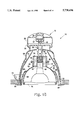
- FIG. 4 is an elevational view of the lighting fixture embodying the present invention, as shown in FIG. 1 except for showing the reflector support member in section, wherein the lighting fixture is shown in a tilted position to direct illumination in a direction angled from a vertical direction;
- FIG. 5 is an elevational view of a lighting system comprising a plurality of lighting fixtures embodying the present invention
- FIG. 6 is a top view of the piercing module of the lighting fixture embodying the present invention.
- FIG. 7 is a cross-sectional view of the piercing module of the light fixture embodying the present invention, taken along the line 7--7 of FIG. 6
- FIG. 8 is a cross-sectional view of the piercing module of the lighting fixture embodying the present invention, taken along the line 8--8 of FIG. 6;
- FIG. 9 is a cross-sectional view of the latching mechanism of the piercing module, showing the position of the respective components prior to insertion of an insulated cable in the piercing module;
- FIG. 10a is a longitudinal sectional view of the piercing module of the lighting fixture embodying the present invention, showing the latching mechanism position prior to closure;
- FIG. 10b is a cross-sectional view of the latching mechanism in the position shown in FIG. 10a;
- FIG. 11 is a longitudinal-sectional view of the piercing module of the lighting fixture embodying the present invention, showing the latching mechanism at a position intermediate to an open and closed position;
- FIG. 12a is a longitudinal-sectional view of the piercing module of the lighting fixture embodying the present invention, showing the latching mechanism at its maximum compression position;
- FIG. 12b is a cross-sectional view of the latching mechanism when disposed at the position shown in 12a;
- FIG. 13 is a longitudinal-sectional view of the piercing module component of the lighting fixture embodying the present invention showing the latching mechanism at a fully closed, over center, position;
- FIG. 14 is a top view of another embodiment of the lighting fixture embodying the present invention.
- FIG. 15 is a cross-sectional view taken along the line 15--15 of FIG. 14;
- FIG. 16 is a cross-sectional view taken along the line 16--16 of FIG. 14;
- FIG. 17 is a sectional view of a portion of one arrangement of the reflector and heat sink modules of the lighting fixture embodying the present invention.
- FIG. 18 is a top view of the heat sink shown in section in FIG. 17, adapted for use in the lighting fixture embodying the present invention.
- FIG. 19 is a plan view of an alternative embodiment of a lighting fixture embodying the present invention.
- FIG. 20 is a cross-sectional view of the alternative embodiment of the lighting fixture, taken along the line 20--20 of FIG. 19;
- FIG. 21 is a cross-sectional view of the alternative embodiment of the lighting fixture, taken along the line 21--21 of FIG. 20;
- FIG. 22 is an exploded three-dimensional view of portions of the electrical power module of the alternative embodiment of the lighting fixture embodying the present invention.
- FIG. 23 is a plan view of one of a pair of mating circuit member mounting bodies of the lighting fixture embodying the present invention.
- FIG. 24 is a three-dimensional view of one of the mating halves of the circuit member mounting body of the lighting fixture embodying the present invention, showing a thermal cutout member interposed between two components of an electrical circuit.
- a lighting fixture 10 embodying the present invention comprises three modular components.
- the lighting fixture 10 is a recessed fixture adapted for use in either new or existing construction and, as best shown in FIG. 2, comprises a piercing module 12, a heat sink module 14, and a reflector module 16.
- the lighting fixture 10 is adaptable to virtually any lighting system, i.e., low voltage, line voltage, halogen, fluorescent, incandescent, or other system by providing a heat sink module 14 adapted to the desired specific system.
- the piercing module 12 is capable of providing electrical connection with insulated, non-metallic sheathed, stranded wires within a preselected limited range of sizes, for example, 10 to 14 gage.
- the piercing module 12 permits a single continuous insulated stranded cable 18 to enter and exit the fixture 10, as described below in greater detail, so that a plurality of the fixtures 10 may be arranged serially, as shown in FIG. 5, without interconnection with intervening junction boxes.
- the electrical cable 18 is a 10-gage, 2-wire type NM sheathed cable rated at 600 volts, having about 105 strands per wire.
- the outer sheath and inner wire insulation have a temperature rating of at least about 90° F.
- the cable 18 is conveniently connectable to an existing outlet box 20, either by connection to the wires conventionally provided in the outlet box 20 or by external plug attachment to the socket provided in the outlet box 20.
- the outlet 20 may also comprise a transformer to step down the line voltage to the desired low voltage requirements, e.g., 12 volts.
- the outlet 20 may comprise a conventional wall switch to control the operation of the fixtures 10.
- the wire 18 may be connected directly to the switch 20.
- the outlet 20 may also comprise a remotely controlled switch.
- a lighting system comprising the lighting fixtures 10 embodying the present invention is easily installed in either new or existing construction.
- the cable 18 may be conveniently preconnected to a source 20 of electrical power and then arranged in a random pattern in the approximate area where the fixtures are to be subsequently installed. Precise prepositioning of the wire 18 is not required.
- the fixture 10 also includes a means for retaining the fixture 10 in the opening 22.
- the retaining means includes a plurality of spring clips 23 attached to the reflector module 16.
- Other spring biased clips such as the tabs 73 shown in FIGS. 14-16 that extend radially outwardly from the reflector module 16, may also be used.
- the entire fixture installation process is very simple and requires only a minimal amount of time, for example, less than three to five minutes to drill the hole, position and pierce the wire, and insert the fixture.
- the piercing module 12 may comprise a conventional piercing arrangement such as that used on outdoor low-voltage lighting systems, or on connectors used to attach Christmas tree lights at selected positions along a wire.
- the outdoor low voltage system typically comprises a pair of blades, or pins, in the bottom of a holder, which pierce the insulation of a wire placed over the pins in response to screwing on a cap or wedging a closure member into place over the wire.
- the piercing module 12 comprises a lever-actuated locking cam arrangement, shown in detail in FIGS. 6-13, that is laterally removable to facilitate placement of the cable 18 into the piercing module 12.
- the piercing module 12 includes a base member 24 and an upper member 26 attached to the base member 24 by a pair of screws 28.
- the upper member 26 has a longitudinal channel 30 defined by walls having a length that extend completely across the piercing module 12 and are shaped to mate with the outer surface of the continuous insulated electrical cable 18 which, when placed in the channel 30, is preferably in tightly abutting contact with the bottom and sides of the channel 30.
- the piercing module 12 also includes a means 32 for piercing the insulation of the continuous insulated cable 18 and providing electrical communication between cable 18 and the piercing means 32. More specifically, the piercing means 32 comprises a pin 34 for each of the wires in the electrical cable 18 which, in the illustrated embodiment, comprises two wires.
- the pins 34 are rigidly mounted in the upper member 26 and have a pair of electrical leads 36 attached to a lower portion of the pins 34.
- the electrical leads 36 extend through the base member 24 and have connectors attached to their respective outer ends.
- the electrical leads 36 are preferably attached to a respective one of the pins 34, such as by soldering, prior to inserting the pins 34 into the upper member 26.
- the pins 34 are laterally aligned with each other, whereas in other embodiments the pins 34 may be staggered to provide increased longitudinal spacing between the pins.
- the piercing means 32 also includes a pressure plate 37 that is adapted to mate with and partially surround a portion of the cable 18 and provide tightly abutting contact with the cable 18.
- the pressure plate 37 has a square shape with the bottom contoured to mate with a predefined cable size, e.g., 10 ga, when oriented in a first direction, and with a differently sized cable, e.g., 12 ga, when rotated 90°.
- the piercing means 32 also includes a means for forcibly moving the pressure plate 37 in a direction toward the pins 34.
- the means of removing the pressure plate includes a lever-actuated cam 38 that is rotatably mounted on a cam support member 40.
- the cam support member 40 is slidably movable in a lateral direction with respect to the longitudinal channel 30 formed in the upper member 26 of the piercing module 12. However, when inserted into the upper member 26, the cam support member 40 is restrained from vertical displacement with respect to the upper member 26.
- FIGS. 9-13 The insertion and piercing of the cable 18 in the piercing module 12 is illustrated in FIGS. 9-13.
- the cam support member 40 having the lever-actuated cam 38 rotatably mounted therein is moved laterally to expose the longitudinal channel 30 formed in the upper member 26 of the piercing module 12.
- the cable 18 is then inserted into the channel and the pressure plate 37 is placed over the cable 18.
- the lever-actuated cam 38 is rotated to the position shown in FIG. 10a to provide clearance for the cam 38 over the pressure plate 37.
- the cam support member 40 is then moved laterally to a position shown in 10b whereat the lever-actuated cam 38 is centered over the pressure plate 37.
- the lever-actuated cam 38 is then rotated in a counter-clockwise direction, as shown in FIG. 11, to move the pressure plate into forced contact with the cable 18.
- Rotation of the lever-actuated cam 38 is continued, as illustrated in FIG. 12a, and 12b, whereat the cable 18 is forced downwardly over the pointed ends of the pins 34 so that the pointed ends penetrate the insulation of the cable 18 and contact the stranded wires disposed within the cable 18.
- Rotation of the lever-actuated cam 38 is then continued until the cam 38 is at an over-center position and the lever end of the cam 38 is forcibly maintained at a position flush with the upper member 26, as shown in FIG. 13.
- the heat sink module 14 is detachably connectable, either directly or indirectly, to the piercing module 12.
- the heat sink module 14 has a heat sink 42 having a central bore 44 formed therethrough that provides a mounting cavity for a bulb-receiving socket 46.
- the heat sink 42 is disposed within a single wall housing 48, preferably formed of a high temperature polyetherimide resin such as glass reinforced ULTEM® produced by General Electric.
- the heat sink 42 is retained in the housing 48 by one or more knurled screws 49 extending through the wall of the housing 48.
- the housing 48 provides direct connection of the heat sink module 14 to the piercing module 12, either by screws extending from one member to the other or by a snap engagement, interference fit between the housing 48 and the base member 24 of the piercing module 12, as shown by way of example in FIG. 17..
- the heat sink 42 may be exposed directly to the surrounding environment, i.e., without a surrounding housing, in which arrangement the base member 24 of the piercing module 12 may be directly attached to the heat sink 42 via screws.
- the housing 48 may comprise double cylindrical walls, one radially spaced from the other, to provide additional isolation of the heat sink 42 from the external surface of the lighting fixture 10.
- the heat sink module 14 and the reflector module 16 are completely enclosed within an outer cover. In this arrangement, the heat sink module 14 is indirectly connected to the piercing module 12 via the cover enclosing the modules.
- the heat sink 42 is formed of a metallic material having high thermal conductivity, such as aluminum.
- the outer circumferential surface of the heat sink preferably is shaped to provide a plurality of fins 50 as shown in FIG. 18.
- the central bore 44 of the heat sink 42 is relieved to provide clearance for a socket hanger 52 which extends upwardly through the bore 44 and then extends laterally across the top of the heat sink 42 whereat it is secured to the heat sink via screws 54 that engage screw holes provided in a radially outer portion of the heat sink 42.
- electrical leads from the socket 46 Prior to assembly of the heat sink module 14 to the piercing module 12, electrical leads from the socket 46 are connected to the leads 36 extending from the pins 34, thereby providing electrical communication between the piercing pins 34 and the socket 46.
- the reflector module 16 of the lighting fixture 10, embodying the present invention includes a trim ring 56, a reflector support member 58, and a reflector 60 that is detachably connectable, either directly or indirectly, to the heat sink module 14.
- the heat sink housing 48 may be integrally formed with the reflector 60, and the heat sink module 14, comprising the heat sink 42 and socket 46, detachably mounted in the integrally formed housing 48.
- the reflector support member 58 is concentrically disposed with respect to the trim ring 56 about a longitudinal axis that is perpendicular to the mounting surface of the fixture 10.
- the reflector 60 is rotatably mounted in the reflector support member 58 by a pair of pins 62, one of which may be seen in FIGS. 3 and 4.
- the pins 62 are integrally formed with the reflectors 60 and extend, by snap fit, into holes provided in the reflector support member 58.
- the reflector 60 is preferably spherically shaped and is capable of rotation, or tilting, within the reflector support member 58 to an angle ⁇ from a line 59 perpendicular to the mounting surface.
- the angle ⁇ has a range from 0° to about 35° in either direction from the perpendicular line.
- the reflector 60 has a total range of adjustability of about 70°.
- the reflector module 16 also includes a means for maintaining the reflector 60 at a desired angle ⁇ with respect to the perpendicular line 59.
- the outer surface of the reflector 60 is shaped to provide a series of reaction surfaces adapted to receive a detent member that is in biased contact with the surface.
- the outer surface of the reflector 60 is defined by a series of stepped, progressively smaller diameter, concentric rings 64.
- Two detent members 66 integrally formed with the reflector support member 58, have an inwardly extending lip or finger that is shaped to engage one of the concentric rings 64 on the outer surface of the reflector 60.
- the length of the fingers on the detent members 66 are slightly longer than the free clearance distance between the inwardly extending end of the detent member 66 and the outer surface of the reflector 60.
- detent members 66 are forced outwardly thereby creating a bias force bearing against the outer surface of the reflector.
- the created bias force is sufficient to maintain the reflector 60 at a respective angled position ⁇ with respect to the reflector support member 58, and still permit angular adjustment of the reflector, even after installation of the light fixture 10 in a ceiling or other panel.
- the means for maintaining the reflector 60 at a predetermined angled position may comprise a plurality of aligned recesses in the outer surface of the reflector 60, with the detent members comprising a small ball, pin, or other shape adapted to engage the recesses provided in the outer surface of the reflector 60.
- the reflector 60 is also formed of a high temperature plastic resin material, and, if desired, may be coated with a reflective material to direct heat, and light if the bulb does not have an integral reflector formed therein, downwardly from the fixture 10.
- the housing also be formed of a high temperature plastic material.
- Other less heat-sensitive components of the light fixture 10, such as the piercing module 12 and the reflector support member 58 may be formed of a lower temperature service-rated plastic material, for example a thermoplastic polyester resin such as VALOX®, also produced by GE Plastics.
- the trim ring 56 may be integrally formed with the reflector support member 58, or as shown in FIGS. 15 and 16, may be assembled to the reflector support member 58 by providing a snap engagement, interference fit between the two members.
- the light fixture 10 in another embodiment of the light fixture 10 embodying the present invention, shown in FIGS. 14-16, includes a detachable cover 68 that surrounds the reflector module 16 and the heat sink module 14.
- the detachable cover 68 is spaced from the heat sink and reflector modules 14, 16 and provides a heat sealing enclosure around the heat sink and reflector modules 14, 16.
- a basket sleeve 70 formed of heat conducting material such as aluminum, is disposed circumferentially around the reflector and heat sink modules 16, 14 at a position between the modules and the cover 68.
- the basket sleeve 70 comprises a plurality of spaced apart fingers having ends that are adjacent the upper end of the heat sink module 14.
- the interior surface of the detachable cover 68 is also coated with a heat reflective material such as aluminum to reflect heat from the cover inwardly to the heat conducting basket sleeve 70.
- a heat reflective material such as aluminum to reflect heat from the cover inwardly to the heat conducting basket sleeve 70.
- the sleeve 70 is mounted in grooves formed on the inner side of the trim ring 56 which, in this embodiment, is formed of a heat conducting material such as aluminum or steel.
- heat is transferred by conduction from the sleeve 70 to the heat conducting trim ring 56 and dissipated into the surrounding environment.
- the trim ring 56 may be formed of a plastic material having good heat transfer properties or may comprise a metal ring seated in the trim ring 56. It should also be noted, that in this embodiment, the piercing module 12 is detachably mounted directly on top of the detachable cover 68.
- FIGS. 14-16 The embodiment of the light fixture shown in FIGS. 14-16 in which a detachable cover encloses the heat-generating components of the fixture 10, is particularly desirable in insulated ceiling installations and other installations in which combustible material may come into contact with, or into close proximity with, the lighting fixture 10.
- the fixture 10 is retained in the opening 22 by a plurality of outwardly extending tabs 73 that are integrally formed with the reflector support member 58.
- the tabs 73 are formed so that, in their free state, they extend radially outwardly from the outer surface of the reflector support member 58.
- the heat conducting sleeve 70 and outer cover 68 are provided with slots through which the tabs 73 extend.
- the tabs 73 Prior to installation through the opening 22, the tabs 73 are compressed radially inwardly and held until they clear the opening 22. Upon release, the tabs 73 spring outwardly until their bottom tapered edge contacts the side of the opening 22 and thereby retains the fixture 10 in the opening 22.
- the heat sink 42 may be directly exposed to the surrounding environment as described above.
- the housing 48 surrounding the heat sink 42 may have a plurality of slots 72, as shown in FIGS. 1-5 and 17, that extend through the housing 48 at regularly spaced radial positions above the heat sink 42. In the latter arrangement, heated air will rise through the heat sink 42 and then be discharged through the slots 72 to the surrounding environment.
- a ballast or other electronic circuit may be required for operation of the bulb.
- an intermediate module not shown, containing the required ballast or circuitry, may be conveniently inserted between the piercing module 12 and the heat sink module 14.
- the intermediate module is detachably connected, such as by snap engagement of the respective housings.
- a conventional "smart module” containing a receiver and appropriate control circuits for remote operation of the light fixture, may be enclosed in an intermediate housing detachably positioned between the piercing module 12 and the heat sink module 12 either in addition to the ballast and specific system circuitry, or by itself.
- the "smart module” would permit operation of the light fixture by a remote hand held or wall-mounted transmitter.
- a detachable holder 74 may be mounted, either by friction engagement, clips, or snap engagement interference fit as shown in FIGS. 16 and 17, to the bottom of the reflector 60.
- the holder 74 may conveniently support a color filter, louver, lens, or other light conditioning or modifying element.
- FIGS. 19-24 Another alternative embodiment of the present invention is illustrated in FIGS. 19-24.
- a modular lighting fixture 100 has an integrated electrical power module 102 and a lamp shield module 104.
- the electrical power module 102 has a circuit member mounting body 106 that is disposed within a housing 108, as best shown in FIG. 22.
- the power module 102 further includes a first means 110 for piercing the insulation of two wires of a continuous electrical cable when the cable is inserted through the lighting fixture 100 and a second means 112 for receiving an electric lamp 114 and maintaining the lamp 114 in a fixed position with respect to the power module 102.
- the first means 110 for piercing the insulation of two wires of a continuous insulated cable comprises a pair of spaced apart piercing pins 116 having sharply pointed tips at their respective ends.
- the electrical power module 102 further includes separate first and second electrical circuits 118, 120, as best seen in FIGS. 23 and 24, that extend between the first means 110 for piercing the wires and the second means 112 for retaining the lamp.
- the first and second electrical circuits 118, 120 provide respective separate electrical communication between the first means 110 and the second means 112.
- the first electrical circuit comprises an elongated strip 122 that is desirably formed by stamping the strip 122 from a sheet of electrically conductive material, such as beryllium copper.
- One of the pair of pins 116 is integrally formed on a first end of the strip 122, and an open ended cylindrical socket 124, representing a portion of the second means 112 for receiving an electric lamp 114 and maintaining the lamp 114 in a fixed position with respect to the power module 102, is integrally formed on a second end of the strip 122.
- the socket 124 may be viewed as having a semi-cylindrical shape or alternatively described as having a full cylindrical shape with a longitudinal slot extending along one side of the cylinder. In either characterization, the socket 124 has a bore 126 that is adapted to engage a pin of the lamp 114 when the lamp 114 is inserted in the fixture 100.
- the lamp 114 comprises a 12 volt type MR16 halogen lamp.
- Other socket arrangements for the power module 102 that are adapted for other lamps, such as non-halogen incandescent bulbs and fluorescent lamps, may be interchanged for the socket arrangement described above.
- the second electrical circuit 120 includes a thermal cutout member 128, such as a KLIXON® switch produced by Texas Instruments, which opens in response to sensing a temperature above a predetermined value.
- a thermal cutout member 128, such as a KLIXON® switch produced by Texas Instruments, which opens in response to sensing a temperature above a predetermined value.
- the thermal cutout member 128 is interposed between a first electrically conductive member 130 that has another one of the pair of piercing pins 116 integrally formed on a first end, and a tab 132 integrally formed on a second end.
- the tab 132 is adapted to mate with one of the contacts of the thermal cutout 128.
- the second electrical circuit 120 also includes a second electrically conductive member 134 that has another one of pairs of the sockets 124 integrally formed on a first end of the second member 134 and a tab 136 integrally formed on a second end that is adapted to mate with the another contact of the thermal cutout member 128.
- the second means 112 for receiving an electrical lamp and maintaining the lamp in a fixed position with respect to the power module also includes a pair of springs 138, preferably formed of spring steel, which are fixedly mounted in cantilevered fashion in the circuit member mounting body 106.
- Each of the springs 138 are disposed in respective alignment with the open side of one of the sockets 124 at a position where the spring provides a bias force against an external surface of a respective pin of the lamp 114 when the pin base of the lamp 114 is inserted into the socket 124.
- the circuit member mounting body 106 of the power module 102 is formed by joining two mating halves 140, which are mirror images of each other, together to form a single structure.
- the mating halves 140 are desirably formed of a high temperature, injection moldable, electrically nonconductive thermoplastic material, such as a polyetherimide resin, with the respective components of the first and second electrical circuits 118, 120 heat staked to a respective one of the halves 140 before joining the two halves together.
- a polyetherimide resin such as a polyetherimide resin
- the thermal cutout member 128 is inserted into a cavity 142 formed in the mating halves 140, with each of the contacts of the thermal cutout member 128 bearing against a respective one of the tabs 132, 136.
- the mating halves 140 may then joined by ultrasonic welding, adhesives, or other assembly technique of choice, to form the circuit member mounting body 106.
- a center portion 144 of the elongated strip disposed in contact with the thermal cutout member 128 is removed by inserting a punch through a window 145, provided in the mating half structure 140, and severing the center portion 144 from the elongated strip.
- the separate first and second electrically conductive members 130, 134 of the second electrical circuit 120 are thus formed with each member 130, 134 being rigidly embedded within the mounting body 106.
- thermal cutout member 128 is advantageously positioned within the mounting body 106 in fixed relationship with respect to the electrically conductive tabs 132, 136 of the conductive members 130, 134.
- the internally disposed components of the first and second electrically conductive circuits 118, 120 provide the structural strength for support of the piercing pins 116, the sockets 124, and the springs 138.
- the first electrical circuit 118 provides an electrically conductive path from a first one of the piercing pins 116, through the continuously elongated strip 122, to a first one of the sockets 124, all of which are formed as a single, unitary structure.
- the second electrical circuit 120 which is interruptible, or capable of being opened, if a predetermined operating temperature is exceeded, comprises an electrically conductive path from a second one of the pins 116, through the first electrically conductive member 130, to the tab 132, thence through the thermal cutoff member 128 to the tab 136 of the second electrically conductive member 134, and through the second electrically conductive member 134 to the second one of the sockets 124.
- both the first and second electrical circuits 118, 120 may be formed as single, one-piece elongated strips 122, as described above with respect to the first electrically conductive member 118.
- the mounting body 106 is inserted into the power module housing 108 which, preferably, is formed of the same high temperature, electrically nonconductive thermoplastic material as the body 106.
- the mounting body 106 may be secured in fixed position with respect to the housing 108 by mechanical devices such as cooperating tabs and grooves, screws, pins or, preferably by ultrasonically welding selected mutually abutting surfaces of the two members whereby the circuit member mounting body 106 and the housing 108 form a single, unitary structure with two separate electrical circuits, one of which may contain a thermal cutout switch, embedded within the single structure.
- the lighting fixture 100 further includes a movable pressure member adapted to biasedly contact a portion of a cable extending through the power module 102 and a means 148 for forcibly moving the pressure member in a direction toward the pins 116.
- a movable pressure member is provided by an annular ring 150 formed at a distal end of a cylinder extending downwardly from a removable cap 152, as illustrated in cross section in FIGS. 20 and 21.
- the means 148 for forcibly moving the pressure member 150 in a direction toward the pins 116 is provided by the raised spiral surfaces 146, best seen in FIG. 22, which cooperate with an inwardly extending flange 154, viewable in FIG.
- the lamps shield module 104 has a first portion 158 that is attachable, by mechanical means or, preferably. by ultrasonic welding, to the electrical power module 102, and a second portion 160 that is rotatably mounted on the first portion 158, as described earlier with respect to an initial embodiment.
- a pair of oppositely spaced support pins 162 are integrally formed with the first portion 158 of the lamp shield module 104 and snap into holes formed in the second portion 160.
- the first portion 158 is rotatably movable with respect to the second portion 104 about an axis 164 extending through the support pins 162 of the second portion 160.
- the first portion 158 of the lamp shield module 104 is preferably also formed of the same high temperature, electrically nonconductive, injection moldable thermoplastic material as the circuit member mounting body 106, and has an upper annular wall 166 disposed adjacent to the power module 102 and a lower annular wall 168 formed at a lower open end of the lamp shield module 104.
- the first portion 158 of the lamp shield module also has an interior surface 170 that extends between the upper and lower annular walls 166, 168. If desired, a trim ring 172 may be mounted on the lower annular wall 168 of the first portion 158 of the lamp shield module 104.
- the trim ring 172 may be formed of a resilient material, such as silicon rubber, and extend radially outwardly into abutment with the interior wall of the second portion 160 and form a flexible seal between the exterior wall of the first portion 158 and the interior wall of the second portion 160 of the lamp shield module 104.
- a dead air insulating space 179 is provided between the lamp 114 and an outer surface of the lamp shield module 104.
- a truncated conically-shaped thermal radiant reflector 174 formed of aluminum or similar material having high heat reflectance properties, is disposed inwardly from the interior surface 170 of the first portion 158.
- An annular elastomeric gasket 176 e.g., formed of silicone rubber, is interposed between the thermal radiant reflector 174 and the upper annular wall 166 of the first portion 158.
- An annular O-ring 178 is interposed between the thermal radiant reflector 174 and a groove formed in the lower annular wall 168 of the first portion 158 of the lamp shield module 104.
- the air-tight, sealed chamber 179 advantageously prevents high thermal conductance between the lamp 114 and the outer surfaces of the lighting fixture 100.
- the lamp shield module 104 further includes a means 180 for maintaining the first portion 158 of the lamp shield module 104 in a selected angular relationship with respect to the second portion 160 of the lamp shield module 104.
- the angular retaining means 180 is provided by a plurality of surface features, for example, ridges 182 defined on the outer surface of the first portion 158 of the lamp shield module 104, which are adapted to receive one or more detent members 184 that are integrally formed with the second portion 160 of the lamp shield module 104. As best shown in FIG.
- a pair of equally spaced apart detent members 184 have an inwardly extending finger which is in biased contact with a respective one of the ridges 182 on the outer surface of the first portion 158.
- the detent members 184 forcibly engage respective ridges, as shown in FIG. 20.
- the detent members 184 are disposed at right angles with respect to the support pins 162, so that when the first portion 158 of the lamp shield module 104 is tilted, or rotated about the axis 164, the detente members 158 maintain the thus selected tilted relationship between the first portion 158 and the second portion 160 of the lamp shield module 104.
- the lamp shield module 104 also includes a means 186 for retaining the lighting fixture 100 in a fixed relationship with respect to an opening in a predefined mounting surface, such as a ceiling, when the lighting fixture 100 is mounted in the opening.
- the light fixture retaining means 186 comprises a plurality of spring clips 188 that are mounted on the second portion 160 of the lamp shield module 104 and extend radially outwardly from the second portion 160 to engage a surface, such as a ceiling, surrounding an opening in which the lighting fixture 100 is installed.
- the electric power module 102 and the lamp shield module 104 may be separately configured to form a variety combinations suitable for specific lighting and lamp applications.
- the second means 112 for receiving an electric lamp and maintaining the lamp in a fixed position with respect to the power module 102 may comprise a screw-threaded socket to receive an incandescent bulb, or have another configuration for a fluorescent bulb.
- a third pin 116 may be provided as a part of the piercing means 110.
- the thermal radiant reflector 174 that partially defines the dead air chamber 179 and/or the thermal cutout member 128, may not be required.
- a piercing means as described above with respect to FIGS. 6-13 or other piercing means, may be substituted for the screw-down cap 152.
- the lighting system 10 embodying the present invention provides a versatile arrangement that can be readily adapted to low voltage, line voltage, a plurality of bulb types, or installation in either insulated or noninsulated ceilings.
- the lighting fixtures 10 embodying the present invention can be marketed as kits with common piercing modules 12 and reflector modules 16, and a heat sink module 14 specifically adapted to a specific lighting system.
- the commonality of modules between the various systems provides manufacturing economy and reduced parts inventory. If the lighting fixture 10 is to be installed in an insulated ceiling, or other installation requiring a low temperature outer surface for the fixture, the detachable cover 68 and heat conducting sleeve 70 may be added separately or provided in the kits containing the basic components of the fixture.
- the modular lighting fixture 10 embodying the present invention provides an economical, easy-to-install fixture that may be sold as prepackaged modules, or as components of a kit, that are easily assembled at the job site and installed by professionals or do-it-yourselfers in new or pre-existing structures.
Abstract
Description
Claims (22)
Priority Applications (4)
| Application Number | Priority Date | Filing Date | Title |
|---|---|---|---|
| US08/862,334 US5738436A (en) | 1996-09-17 | 1997-05-23 | Modular lighting fixture |
| PCT/US1998/004617 WO1998053248A1 (en) | 1997-05-23 | 1998-03-09 | Modular lighting fixture |
| US09/057,769 US6375338B1 (en) | 1996-09-17 | 1998-04-09 | Modular lighting fixture |
| CA002238212A CA2238212C (en) | 1997-05-23 | 1998-05-22 | Modular lighting fixture |
Applications Claiming Priority (2)
| Application Number | Priority Date | Filing Date | Title |
|---|---|---|---|
| US71494096A | 1996-09-17 | 1996-09-17 | |
| US08/862,334 US5738436A (en) | 1996-09-17 | 1997-05-23 | Modular lighting fixture |
Related Parent Applications (1)
| Application Number | Title | Priority Date | Filing Date |
|---|---|---|---|
| US71494096A Continuation-In-Part | 1996-09-17 | 1996-09-17 |
Related Child Applications (1)
| Application Number | Title | Priority Date | Filing Date |
|---|---|---|---|
| US09/057,769 Continuation US6375338B1 (en) | 1996-09-17 | 1998-04-09 | Modular lighting fixture |
Publications (1)
| Publication Number | Publication Date |
|---|---|
| US5738436A true US5738436A (en) | 1998-04-14 |
Family
ID=25338243
Family Applications (2)
| Application Number | Title | Priority Date | Filing Date |
|---|---|---|---|
| US08/862,334 Expired - Fee Related US5738436A (en) | 1996-09-17 | 1997-05-23 | Modular lighting fixture |
| US09/057,769 Expired - Fee Related US6375338B1 (en) | 1996-09-17 | 1998-04-09 | Modular lighting fixture |
Family Applications After (1)
| Application Number | Title | Priority Date | Filing Date |
|---|---|---|---|
| US09/057,769 Expired - Fee Related US6375338B1 (en) | 1996-09-17 | 1998-04-09 | Modular lighting fixture |
Country Status (3)
| Country | Link |
|---|---|
| US (2) | US5738436A (en) |
| CA (1) | CA2238212C (en) |
| WO (1) | WO1998053248A1 (en) |
Cited By (152)
| Publication number | Priority date | Publication date | Assignee | Title |
|---|---|---|---|---|
| US6030102A (en) * | 1998-12-23 | 2000-02-29 | Cooper Technologies Company | Trim retention system for recessed lighting fixture |
| US6068387A (en) * | 1999-01-19 | 2000-05-30 | Cooper Technologies Company | Light fixture with trim mounting clip |
| US6082878A (en) * | 1998-02-03 | 2000-07-04 | Cooper Industries, Inc. | Fully rotatable recessed light fixture with movable stop and adjustable length bar hanger |
| EP1016819A1 (en) * | 1998-12-29 | 2000-07-05 | Störi Einbau-Licht AG | Recessed lighting fixture and suspended ceiling with a recessed lighting fixture |
| US6164802A (en) * | 1998-12-23 | 2000-12-26 | Cooper Technologies Company | Stackable housing |
| EP0961078A3 (en) * | 1998-05-28 | 2001-05-30 | RIDI-LEUCHTEN GmbH | Recessed lighting fixture |
| US6264344B1 (en) | 1998-06-03 | 2001-07-24 | Spaulding Lighting, Inc. | Canopy luminaire assembly |
| US6313570B1 (en) | 1999-02-18 | 2001-11-06 | Lars Anders Bergkvist | High intensity gas discharge aircraft lighting |
| US6464377B2 (en) * | 1997-04-17 | 2002-10-15 | Stingray Lighting, Inc. | Dual reflector lighting system |
| WO2002097933A1 (en) * | 2001-05-25 | 2002-12-05 | Power & Light Llc | Lighting fixture assembly |
| US20020191396A1 (en) * | 2001-04-11 | 2002-12-19 | Reiff Paul J. | LED work light |
| US6568826B1 (en) * | 1999-10-13 | 2003-05-27 | Irwin Kotovsky | Lighting apparatus and method |
| WO2003095892A1 (en) * | 2002-05-11 | 2003-11-20 | Michael Man-Cheung Tsang | Fitting protector |
| DE10227621A1 (en) * | 2002-06-20 | 2004-01-08 | Licht + Design Gmbh | Light has reflector that protrudes slightly from light housing attached to carrier, and can be attached to/removed from reflector holder from outside base part without dismantling light housing or carrier |
| US20040165411A1 (en) * | 2002-03-20 | 2004-08-26 | Heath Eric W. | Polyetherimide lamp socket assembly |
| US20050007031A1 (en) * | 2003-07-11 | 2005-01-13 | Hubbell Incorporated | Low voltage luminaire assembly |
| US20050036321A1 (en) * | 2003-08-13 | 2005-02-17 | Ardee Lighting /Usa, Inc. | Recessed downlight lighting apparatus |
| US6883941B2 (en) | 2002-09-23 | 2005-04-26 | Steven B. Cutting | Landscape light fixture |
| US20050230589A1 (en) * | 2004-03-25 | 2005-10-20 | Cooper Technologies Company | Hangar bar for recessed luminaires with integral nail |
| US20050247842A1 (en) * | 2004-05-10 | 2005-11-10 | Grzegorz Wronski | Hanger bar assemblies for recessed luminaires |
| US20050276053A1 (en) * | 2003-12-11 | 2005-12-15 | Color Kinetics, Incorporated | Thermal management methods and apparatus for lighting devices |
| US7032614B2 (en) | 2000-11-03 | 2006-04-25 | Applied Materials, Inc. | Facilities connection box for pre-facilitation of wafer fabrication equipment |
| US20060109662A1 (en) * | 2001-04-11 | 2006-05-25 | Reiff Paul J | Intrinsically safe light |
| GB2421073A (en) * | 2004-12-08 | 2006-06-14 | Illuma Lighting Ltd | A combined light and air extraction device |
| US7063301B2 (en) | 2000-11-03 | 2006-06-20 | Applied Materials, Inc. | Facilities connection bucket for pre-facilitation of wafer fabrication equipment |
| US20060262544A1 (en) * | 2005-05-23 | 2006-11-23 | Color Kinetics Incorporated | Modular led-based lighting fixtures having socket engagement features |
| US20060262545A1 (en) * | 2005-05-23 | 2006-11-23 | Color Kinetics Incorporated | Led-based light-generating modules for socket engagement, and methods of assembling, installing and removing same |
| WO2006127785A3 (en) * | 2005-05-23 | 2006-12-28 | Color Kinetics Inc | Modular led lighting apparatus for socket engagement |
| US20070019418A1 (en) * | 2005-07-22 | 2007-01-25 | Ken Czech | Recessed fixture with hinged doors and rotatable lamp |
| US20070063113A1 (en) * | 2005-09-16 | 2007-03-22 | Cooper Technologies Company | Method and apparatus for mounting a lighting device |
| US20070082588A1 (en) * | 2005-09-27 | 2007-04-12 | De Vries Nicholas | Methods and apparatus for coupling semiconductor device manufacturing equipment to the facilities of a manufacturing location |
| US20070091610A1 (en) * | 2005-10-26 | 2007-04-26 | Dorogi Michael J | Lamp thermal management system |
| US20080278957A1 (en) * | 2007-05-07 | 2008-11-13 | Cree Led Lighting Solutions, Inc. | Light fixtures and lighting devices |
| US20080316747A1 (en) * | 2004-09-14 | 2008-12-25 | Koninklijke Philips Electronics, N.V. | Luminaire with Louver Members |
| US7484866B1 (en) | 2006-05-09 | 2009-02-03 | Genlyte Thomas Group Llc | Adjustable lighting fixture for sloped ceiling |
| WO2009029629A1 (en) | 2007-08-27 | 2009-03-05 | Dialight Corporation | Led based hazardous location light with versatile mounting configurations |
| US20090080189A1 (en) * | 2007-09-21 | 2009-03-26 | Cooper Technologies Company | Optic Coupler for Light Emitting Diode Fixture |
| US20090122561A1 (en) * | 2007-11-13 | 2009-05-14 | Daryl Soderman | Light fixture assembly having improved heat dissipation capabilities |
| US20090122553A1 (en) * | 2007-11-13 | 2009-05-14 | Daryl Soderman | Light fixture assembly having improved heat dissipation capabilities |
| US7559677B1 (en) | 2007-09-30 | 2009-07-14 | Genlyte Thomas Group Llc | Recessed luminaire adjustment mechanism |
| US20090273938A1 (en) * | 2008-05-05 | 2009-11-05 | Cooper Technologies Company | Reflector Assembly for a Recessed Luminaire |
| US7625105B1 (en) | 2007-09-18 | 2009-12-01 | Genlyte Thomas Group, Llc | Relamping cartridge assembly |
| US7673842B2 (en) | 2006-07-31 | 2010-03-09 | Koninklijke Philips Electronics, N.V | Captive retaining spring |
| US20100093206A1 (en) * | 2008-10-15 | 2010-04-15 | Checkson Die Casting And Product Factory Limited | Electrical connector for electrical communication between a power cable and an electrical device |
| US20100103621A1 (en) * | 2008-10-27 | 2010-04-29 | Tsung-Ting Sun | Lamp base having a heat sink |
| US20100110699A1 (en) * | 2007-09-27 | 2010-05-06 | Enertron, Inc. | Method and Apparatus for Thermally Effective Removable Trim for Light Fixture |
| US7784754B2 (en) | 2005-12-08 | 2010-08-31 | Genlyte Thomas Group Llc | Adjustable hanger bar assembly with bendable portion |
| US7810960B1 (en) * | 2007-11-13 | 2010-10-12 | Inteltech Corporation | Light fixture assembly having improved heat dissipation capabilities |
| US20110013405A1 (en) * | 2009-07-16 | 2011-01-20 | Koninklijke Philips Electronics N.V. | Recessed light fixture having integrally formed mounting tracks |
| US7874708B1 (en) | 2007-06-26 | 2011-01-25 | Genlyte Thomas Group, Llc | T-bar mounting system |
| EP2284434A1 (en) * | 2008-05-09 | 2011-02-16 | Jinjing Fan | A led bulb for replacing a halogen bulb in the form of reflective cup |
| US7922020B2 (en) | 2006-05-09 | 2011-04-12 | Cooper Technologies Company | Apparatus for securing a line such as a cable |
| US20110164424A1 (en) * | 2010-01-05 | 2011-07-07 | Ideal Industries, Inc. | Electrical Socket, Apparatus and System |
| US20110242826A1 (en) * | 2010-06-25 | 2011-10-06 | Yogen Vishwas Utturkar | Heat Transfer System For A Light Emitting Diode (LED) Lamp |
| US8038327B1 (en) * | 2008-05-06 | 2011-10-18 | Genlyte Thomas Group Llc | Color mixing luminaire |
| US8038321B1 (en) * | 2008-05-06 | 2011-10-18 | Koninklijke Philips Electronics N.V. | Color mixing luminaire |
| WO2012135168A1 (en) * | 2011-03-30 | 2012-10-04 | Osram Sylvania Inc. | Partially recessed luminaire |
| US8360614B1 (en) * | 2007-11-13 | 2013-01-29 | Inteltech Corporation | Light fixture assembly having improved heat dissipation capabilities |
| US8371727B2 (en) | 2011-03-30 | 2013-02-12 | Osram Sylvania Inc. | Partially recessed luminaire |
| US8534873B1 (en) | 2007-11-13 | 2013-09-17 | Inteltech Corporation | Light fixture assembly |
| US20130286669A1 (en) * | 2010-09-20 | 2013-10-31 | Tridonic Connection Technology Gmbh & Co Kg | Device for fastening and contacting a lighting means and/or a lighting module, and lamp |
| CN103542269A (en) * | 2012-07-09 | 2014-01-29 | 海洋王(东莞)照明科技有限公司 | Heat insulation lamp |
| US8643300B1 (en) | 2011-07-21 | 2014-02-04 | Dale B. Stepps | Power control system and method for providing an optimal power level to a designated light fixture |
| US8789980B1 (en) | 2007-11-13 | 2014-07-29 | Silescent Lighting Corporation | Light fixture assembly |
| CN103994350A (en) * | 2014-05-09 | 2014-08-20 | 东莞嘉盛照明科技有限公司 | Light emitting diode lamp |
| US8882532B1 (en) | 2013-12-09 | 2014-11-11 | Kenall Manufacturing Company | Driver box for an improved lighting system |
| US8926133B2 (en) | 2012-09-13 | 2015-01-06 | Lumastream, Inc. | System, method, and apparatus for dissipating heat from a LED |
| US8939418B2 (en) | 2013-04-05 | 2015-01-27 | Cooper Technologies Company | Adjustable hanger bar for luminaires |
| US8944648B1 (en) | 2005-02-25 | 2015-02-03 | Genlyte Thomas Group Llc | Fixture accessory retaining assembly |
| US9055630B1 (en) | 2011-07-21 | 2015-06-09 | Dale B. Stepps | Power control system and method for providing an optimal power level to a designated light assembly |
| USD732225S1 (en) | 2013-12-09 | 2015-06-16 | Kenall Manufacturing Company | Lighting fixture |
| US9060607B1 (en) | 2012-10-17 | 2015-06-23 | Cooper Technologies Company | Hanger bar for recessed light fixture mounting |
| US9062866B1 (en) * | 2012-01-19 | 2015-06-23 | Cooper Technologies Company | Attachment mechanisms for light-emitting diode-based lighting system |
| CN104728638A (en) * | 2015-03-23 | 2015-06-24 | 安徽兆利光电科技有限公司 | LED lamp with thermostat |
| CN104763891A (en) * | 2015-03-23 | 2015-07-08 | 安徽兆利光电科技有限公司 | LED lamp with heat dissipation device |
| US9080760B1 (en) | 2007-11-13 | 2015-07-14 | Daryl Soderman | Light fixture assembly |
| US9109783B1 (en) | 2012-01-19 | 2015-08-18 | Cooper Technologies Company | Secondary enclosure for light-emitting diode-based lighting system |
| US9121590B2 (en) | 2011-03-30 | 2015-09-01 | Osram Sylvania, Inc. | Partially recessed luminaire |
| US9134016B2 (en) | 2012-09-24 | 2015-09-15 | Dasal Industries Ltd. | Adjustable luminaire with slotted arms |
| USD742581S1 (en) | 2013-12-09 | 2015-11-03 | Kenall Manufacturing Company | Driver housing |
| US9192001B2 (en) | 2013-03-15 | 2015-11-17 | Ambionce Systems Llc. | Reactive power balancing current limited power supply for driving floating DC loads |
| US9212792B2 (en) | 2009-07-21 | 2015-12-15 | Cooper Technologies Company | Systems, methods, and devices providing a quick-release mechanism for a modular LED light engine |
| US9239131B1 (en) | 2015-06-05 | 2016-01-19 | Cooper Technologies Company | Adjustable hanger bars with detachment stop |
| US9291319B2 (en) | 2012-05-07 | 2016-03-22 | Cooper Technologies Company | Reflectors and reflector orientation feature to prevent non-qualified trim |
| US9313849B2 (en) | 2013-01-23 | 2016-04-12 | Silescent Lighting Corporation | Dimming control system for solid state illumination source |
| US9310066B2 (en) | 2013-12-09 | 2016-04-12 | Kenall Manufacturing Company | Electronic component for an improved lighting system |
| USD756025S1 (en) * | 2014-04-01 | 2016-05-10 | Cooper Technologies Company | Recessed luminaire housing top |
| US9372207B1 (en) * | 2013-09-10 | 2016-06-21 | EKM Metering, Inc. | Power sensing transducer |
| US9380653B1 (en) | 2014-10-31 | 2016-06-28 | Dale Stepps | Driver assembly for solid state lighting |
| US9400100B2 (en) | 2009-07-21 | 2016-07-26 | Cooper Technologies Company | Interfacing a light emitting diode (LED) module to a heat sink assembly, a light reflector and electrical circuits |
| US9410688B1 (en) | 2014-05-09 | 2016-08-09 | Mark Sutherland | Heat dissipating assembly |
| US20160305628A1 (en) * | 2015-04-16 | 2016-10-20 | Lextar Electronics Corporation | Vehicle lamp |
| US20160312987A1 (en) * | 2015-04-22 | 2016-10-27 | Michael D. Danesh | Outer casing for a recessed lighting fixture |
| US9518723B2 (en) | 2011-04-08 | 2016-12-13 | Brite Shot, Inc. | Lighting fixture extension |
| USD776853S1 (en) | 2013-12-09 | 2017-01-17 | Kenall Manufacturing Company | Lighting fixture |
| US9562627B2 (en) | 2013-12-09 | 2017-02-07 | Kenall Manufacturing Company | Luminaire and improved lighting system |
| US20170167665A1 (en) * | 2015-12-10 | 2017-06-15 | GE Lighting Solutions, LLC | Lighting fixture with replaceable light engine |
| US9696021B2 (en) | 2004-03-25 | 2017-07-04 | Cooper Technologies Company | Hanger bar for recessed luminaires |
| US9726365B1 (en) | 2009-10-05 | 2017-08-08 | Lighting Science Group Corporation | Low profile light |
| US9732904B1 (en) | 2015-06-05 | 2017-08-15 | Cooper Technologies Company | Adjustable hanger bar assembly for luminaires |
| US9739455B2 (en) | 2012-04-17 | 2017-08-22 | Abl Ip Holding Llc | LED light engines |
| USD797980S1 (en) | 2010-05-06 | 2017-09-19 | Lighting Science Group Corporation | Low profile light |
| US9772099B2 (en) | 2009-10-05 | 2017-09-26 | Lighting Science Group Corporation | Low-profile lighting device and attachment members and kit comprising same |
| US9851490B2 (en) | 2009-10-05 | 2017-12-26 | Lighting Science Group Corporation | Light guide for low profile luminaire |
| CN108730852A (en) * | 2018-07-27 | 2018-11-02 | 惠州大亚湾聚欣照明科技有限公司 | A kind of rail mounted LED bar graph lamps and lanterns |
| USD833977S1 (en) | 2015-10-05 | 2018-11-20 | DMF, Inc. | Electrical junction box |
| US10139059B2 (en) | 2014-02-18 | 2018-11-27 | DMF, Inc. | Adjustable compact recessed lighting assembly with hangar bars |
| US20190008057A1 (en) * | 2017-06-28 | 2019-01-03 | The Boeing Company | Attachment apparatus and methods for use |
| US20190093864A1 (en) * | 2017-09-26 | 2019-03-28 | Xiamen Eco Lighting Co. Ltd. | Downlight apparatus |
| US20190115706A1 (en) * | 2016-03-29 | 2019-04-18 | Anyware Solutions Aps | Light socket adapter with ambient sensoring means |
| USD847414S1 (en) | 2015-05-29 | 2019-04-30 | DMF, Inc. | Lighting module |
| US10344952B2 (en) * | 2016-05-24 | 2019-07-09 | Georgi Yosifov Georgiev | Recessed light-emitting diode lighting fixture |
| US20190234577A1 (en) * | 2016-10-17 | 2019-08-01 | Opple Lighting Co., Ltd. | Iillumination device |
| US20190234569A1 (en) * | 2016-10-17 | 2019-08-01 | Opple Lighting Co., Ltd. | Iillumination device |
| US10408395B2 (en) | 2013-07-05 | 2019-09-10 | DMF, Inc. | Recessed lighting systems |
| USD863607S1 (en) * | 2015-07-07 | 2019-10-15 | Auroralight, Inc. | Ball and socket heat exchanger for a light fixture |
| USD864877S1 (en) | 2019-01-29 | 2019-10-29 | DMF, Inc. | Plastic deep electrical junction box with a lighting module mounting yoke |
| US10465885B2 (en) * | 2017-01-31 | 2019-11-05 | Glashütte Limburg Leuchten Gmbh + Co. Kg | Fastening system for luminaires, in particular for recessed ceiling and wall luminaires |
| US10488000B2 (en) | 2017-06-22 | 2019-11-26 | DMF, Inc. | Thin profile surface mount lighting apparatus |
| US10551044B2 (en) | 2015-11-16 | 2020-02-04 | DMF, Inc. | Recessed lighting assembly |
| US10584837B2 (en) | 2016-10-28 | 2020-03-10 | Cordelia Lighting, Inc. | Bar hanger system for recessed fixtures |
| US10655837B1 (en) | 2007-11-13 | 2020-05-19 | Silescent Lighting Corporation | Light fixture assembly having a heat conductive cover with sufficiently large surface area for improved heat dissipation |
| US10663153B2 (en) | 2017-12-27 | 2020-05-26 | DMF, Inc. | Methods and apparatus for adjusting a luminaire |
| US10697599B1 (en) * | 2019-01-17 | 2020-06-30 | Signify Holding B.V. | Adjustable light fixtures |
| US10753558B2 (en) | 2013-07-05 | 2020-08-25 | DMF, Inc. | Lighting apparatus and methods |
| USD901398S1 (en) | 2019-01-29 | 2020-11-10 | DMF, Inc. | Plastic deep electrical junction box |
| USD902871S1 (en) | 2018-06-12 | 2020-11-24 | DMF, Inc. | Plastic deep electrical junction box |
| USD905327S1 (en) | 2018-05-17 | 2020-12-15 | DMF, Inc. | Light fixture |
| US10975570B2 (en) | 2017-11-28 | 2021-04-13 | DMF, Inc. | Adjustable hanger bar assembly |
| US11047557B1 (en) * | 2019-09-03 | 2021-06-29 | George Erik McMillan | Multi-pigtail power module for lighting |
| US11060705B1 (en) | 2013-07-05 | 2021-07-13 | DMF, Inc. | Compact lighting apparatus with AC to DC converter and integrated electrical connector |
| US11067231B2 (en) | 2017-08-28 | 2021-07-20 | DMF, Inc. | Alternate junction box and arrangement for lighting apparatus |
| WO2021174161A1 (en) * | 2020-02-27 | 2021-09-02 | Susan Kelly | Snap-install light assembly and method of use |
| US11143367B2 (en) * | 2019-08-01 | 2021-10-12 | Ningbo Ganpe Optoelectronics Co., Ltd. | Down lamp |
| US11168875B2 (en) * | 2019-08-30 | 2021-11-09 | Xiamen Eco Lighting Co. Ltd. | Downlight apparatus |
| US11231154B2 (en) | 2018-10-02 | 2022-01-25 | Ver Lighting Llc | Bar hanger assembly with mating telescoping bars |
| US11255497B2 (en) | 2013-07-05 | 2022-02-22 | DMF, Inc. | Adjustable electrical apparatus with hangar bars for installation in a building |
| USD945054S1 (en) | 2017-06-22 | 2022-03-01 | DMF, Inc. | Light fixture |
| US11274821B2 (en) | 2019-09-12 | 2022-03-15 | DMF, Inc. | Lighting module with keyed heat sink coupled to thermally conductive trim |
| US11300281B2 (en) * | 2018-03-16 | 2022-04-12 | Luminiz Inc. | Light fixture |
| US11306903B2 (en) | 2020-07-17 | 2022-04-19 | DMF, Inc. | Polymer housing for a lighting system and methods for using same |
| US11391442B2 (en) | 2018-06-11 | 2022-07-19 | DMF, Inc. | Polymer housing for a recessed lighting system and methods for using same |
| US11435064B1 (en) | 2013-07-05 | 2022-09-06 | DMF, Inc. | Integrated lighting module |
| US11466825B2 (en) * | 2020-01-23 | 2022-10-11 | Signify Holding B.V. | Recessed luminaire without an integrated light source |
| EP4071404A1 (en) * | 2021-04-09 | 2022-10-12 | ARTEMIDE S.p.A. | Lighting system |
| USD966877S1 (en) | 2019-03-14 | 2022-10-18 | Ver Lighting Llc | Hanger bar for a hanger bar assembly |
| USD970081S1 (en) | 2018-05-24 | 2022-11-15 | DMF, Inc. | Light fixture |
| US11525557B2 (en) * | 2019-04-11 | 2022-12-13 | Xiamen Eco Lighting Co. Ltd. | Downlight apparatus |
| US11585517B2 (en) | 2020-07-23 | 2023-02-21 | DMF, Inc. | Lighting module having field-replaceable optics, improved cooling, and tool-less mounting features |
| USD990030S1 (en) | 2020-07-17 | 2023-06-20 | DMF, Inc. | Housing for a lighting system |
| US20230332760A1 (en) * | 2023-05-31 | 2023-10-19 | Dongguan Lianrun Lighting Co., Ltd. | Split type single-buckle lamp |
| USD1012864S1 (en) | 2019-01-29 | 2024-01-30 | DMF, Inc. | Portion of a plastic deep electrical junction box |
Families Citing this family (23)
| Publication number | Priority date | Publication date | Assignee | Title |
|---|---|---|---|---|
| US6586672B2 (en) * | 2001-07-17 | 2003-07-01 | Hubbell Incorporated | Electrical insulating box assembly for electrical fixtures |
| US6719438B2 (en) * | 2002-05-09 | 2004-04-13 | Tripar Inc. | Spring for securing trims in recessed lighting housings |
| US6758577B2 (en) * | 2002-07-17 | 2004-07-06 | Wen-Chang Wu | Do-it-yourself lamp structure |
| US7125135B2 (en) * | 2002-10-30 | 2006-10-24 | Patrick Ward | Wall-wash light fixture |
| TW568444U (en) * | 2003-05-07 | 2003-12-21 | De-Shu Gau | Adjustable light-controlled angle detection lamp base |
| US20050239544A1 (en) * | 2004-04-27 | 2005-10-27 | Steelman Paul C | Self-contained integrated audio, lighting and surveillance system |
| US20070058374A1 (en) * | 2005-05-23 | 2007-03-15 | Genlyte Thomas Group, Llc | Luminaire Reflector Having Attachment Ring |
| US7488092B2 (en) * | 2005-08-05 | 2009-02-10 | Genlyte Thomas Group Llc | Track fixture with hinged accessory ring |
| US7445362B2 (en) * | 2006-03-03 | 2008-11-04 | Hubbell Incorporated | Parking garage luminaire with interchangeable reflector modules |
| TW200837308A (en) * | 2006-09-21 | 2008-09-16 | Led Lighting Fixtures Inc | Lighting assemblies, methods of installing same, and methods of replacing lights |
| US8905583B2 (en) * | 2008-06-01 | 2014-12-09 | Jack Guy Dubord | Adjustable light emitting diode lighting assembly, kit and system and method of assembling an adjustable light emitting diode lighting assembly |
| AU2013200866B2 (en) * | 2008-10-03 | 2013-09-19 | Lsi Industries, Inc. | Interchangeable lighting |
| US8382340B2 (en) * | 2008-10-03 | 2013-02-26 | Lsi Industries, Inc. | Interchangeable lightiing |
| US8096686B2 (en) * | 2009-04-21 | 2012-01-17 | Hubbell Incorporated | Trim retention spring and method for recessed lighting fixtures |
| USD671257S1 (en) | 2010-04-10 | 2012-11-20 | Lg Innotek Co., Ltd. | LED lamp |
| IT1401046B1 (en) * | 2010-07-20 | 2013-07-12 | Viabizzuno Srl | PROFILE FOR PANEL FINISHING |
| CN102537719B (en) * | 2010-11-18 | 2015-03-04 | 东芝照明技术株式会社 | Luminaire |
| US20120162994A1 (en) * | 2010-12-22 | 2012-06-28 | Cory Wasniewski | Light Fixture Assembly |
| US8403533B1 (en) | 2011-01-28 | 2013-03-26 | Cooper Technologies Company | Adjustable LED module with stationary heat sink |
| CN102818177B (en) * | 2012-07-23 | 2014-09-10 | 贵州光浦森光电有限公司 | Road lamp adopting installing interface bracket structure |
| WO2016101801A1 (en) * | 2014-12-23 | 2016-06-30 | 武良举 | Lamp |
| WO2017054826A1 (en) | 2015-09-28 | 2017-04-06 | Fischer Lighting Aps | Lamp housing with a locking device |
| RU2639055C1 (en) * | 2017-04-19 | 2017-12-19 | Владимир Александрович Степанов | Device for installation of the built-in lamp |
Citations (16)
| Publication number | Priority date | Publication date | Assignee | Title |
|---|---|---|---|---|
| US2692374A (en) * | 1951-09-20 | 1954-10-19 | Gen Electric | Electric lamp |
| US3231731A (en) * | 1963-08-30 | 1966-01-25 | American Mach & Foundry | Low voltage electrical connector |
| US3359527A (en) * | 1965-08-23 | 1967-12-19 | Oliver M Hart | Portable insulated electric distribution apparatus |
| US4048491A (en) * | 1974-04-08 | 1977-09-13 | Wessman Leonard A | Recessed lighting fixture |
| GB2091955A (en) * | 1981-01-23 | 1982-08-04 | Legrand Sa | Electrical connector for insulated conductors |
| GB2109180A (en) * | 1981-11-04 | 1983-05-25 | Racal Acqustics Limited | Highway cable connector |
| US4450510A (en) * | 1982-04-05 | 1984-05-22 | Nilssen Ole K | Incandescent-fluorescent compatible lighting products |
| US4754377A (en) * | 1986-02-21 | 1988-06-28 | Thomas Industries, Inc. | Thermally protected recessed lighting fixture |
| US4807099A (en) * | 1987-03-11 | 1989-02-21 | Ecp Energy Conservation Products | Lighting fixtures |
| US4930054A (en) * | 1988-12-09 | 1990-05-29 | Nutone, Inc. | Dual cone recessed lighting fixture |
| US4935853A (en) * | 1989-02-03 | 1990-06-19 | Collins William J | Motion-controlled light with arc lamp |
| US5045984A (en) * | 1990-08-10 | 1991-09-03 | Charles Trowbridge | Mounting device for releasable securement to a panel |
| US5055988A (en) * | 1990-03-02 | 1991-10-08 | Schroer Manufacturing Company | Surgery lamp with ventilation for cooling |
| US5136489A (en) * | 1991-06-18 | 1992-08-04 | Cheng Hsiang T | Projective lamp |
| US5385482A (en) * | 1993-09-01 | 1995-01-31 | Georgian Art Lighting Designs, Inc. | Wiring connector device |
| US5601448A (en) * | 1995-03-21 | 1997-02-11 | Sunskill Industries, Ltd. | Connector for lighting system and method |
Family Cites Families (11)
| Publication number | Priority date | Publication date | Assignee | Title |
|---|---|---|---|---|
| US4471414A (en) * | 1982-03-11 | 1984-09-11 | Savage John Jun | Integrated light unit and circuit element attachable to circuit board |
| US4450512A (en) * | 1982-09-13 | 1984-05-22 | Mcgraw-Edison Company | Arrangement for mounting a thermal protective device in a recess mounted lighting fixture |
| US4635172A (en) * | 1985-03-04 | 1987-01-06 | Cooper Industries, Inc. | Recessed lighting fixture having thermal protection |
| US4751623A (en) * | 1986-10-27 | 1988-06-14 | Novo Products, Inc. | Heat deactivated illumination device |
| DE68913043T2 (en) * | 1988-06-29 | 1994-06-30 | Luminaire Dev Ltd | LAMP HOLDER. |
| US5077645A (en) * | 1991-05-15 | 1991-12-31 | Habinak Gerald J | Low voltage halogen lighting fixture |
| US5377087A (en) * | 1992-01-15 | 1994-12-27 | Gulton Industries, Inc. | Passenger reading light |
| JP2779726B2 (en) * | 1992-02-07 | 1998-07-23 | 雅章 鶴薗 | Lighting device for decorative light bulb |
| EP0605200B1 (en) * | 1992-12-26 | 2001-10-04 | Sumitomo Wiring Systems, Ltd. | Press-contact connector assembly |
| US5368503A (en) * | 1993-06-29 | 1994-11-29 | Savage, Jr.; John M. | Apparatus to connect LEDs at display panel to circuit board |
| US5398180A (en) * | 1993-12-17 | 1995-03-14 | Lee; James | Low voltage light fixture |
-
1997
- 1997-05-23 US US08/862,334 patent/US5738436A/en not_active Expired - Fee Related
-
1998
- 1998-03-09 WO PCT/US1998/004617 patent/WO1998053248A1/en active Application Filing
- 1998-04-09 US US09/057,769 patent/US6375338B1/en not_active Expired - Fee Related
- 1998-05-22 CA CA002238212A patent/CA2238212C/en not_active Expired - Fee Related
Patent Citations (16)
| Publication number | Priority date | Publication date | Assignee | Title |
|---|---|---|---|---|
| US2692374A (en) * | 1951-09-20 | 1954-10-19 | Gen Electric | Electric lamp |
| US3231731A (en) * | 1963-08-30 | 1966-01-25 | American Mach & Foundry | Low voltage electrical connector |
| US3359527A (en) * | 1965-08-23 | 1967-12-19 | Oliver M Hart | Portable insulated electric distribution apparatus |
| US4048491A (en) * | 1974-04-08 | 1977-09-13 | Wessman Leonard A | Recessed lighting fixture |
| GB2091955A (en) * | 1981-01-23 | 1982-08-04 | Legrand Sa | Electrical connector for insulated conductors |
| GB2109180A (en) * | 1981-11-04 | 1983-05-25 | Racal Acqustics Limited | Highway cable connector |
| US4450510A (en) * | 1982-04-05 | 1984-05-22 | Nilssen Ole K | Incandescent-fluorescent compatible lighting products |
| US4754377A (en) * | 1986-02-21 | 1988-06-28 | Thomas Industries, Inc. | Thermally protected recessed lighting fixture |
| US4807099A (en) * | 1987-03-11 | 1989-02-21 | Ecp Energy Conservation Products | Lighting fixtures |
| US4930054A (en) * | 1988-12-09 | 1990-05-29 | Nutone, Inc. | Dual cone recessed lighting fixture |
| US4935853A (en) * | 1989-02-03 | 1990-06-19 | Collins William J | Motion-controlled light with arc lamp |
| US5055988A (en) * | 1990-03-02 | 1991-10-08 | Schroer Manufacturing Company | Surgery lamp with ventilation for cooling |
| US5045984A (en) * | 1990-08-10 | 1991-09-03 | Charles Trowbridge | Mounting device for releasable securement to a panel |
| US5136489A (en) * | 1991-06-18 | 1992-08-04 | Cheng Hsiang T | Projective lamp |
| US5385482A (en) * | 1993-09-01 | 1995-01-31 | Georgian Art Lighting Designs, Inc. | Wiring connector device |
| US5601448A (en) * | 1995-03-21 | 1997-02-11 | Sunskill Industries, Ltd. | Connector for lighting system and method |
Cited By (281)
| Publication number | Priority date | Publication date | Assignee | Title |
|---|---|---|---|---|
| US6464377B2 (en) * | 1997-04-17 | 2002-10-15 | Stingray Lighting, Inc. | Dual reflector lighting system |
| US6082878A (en) * | 1998-02-03 | 2000-07-04 | Cooper Industries, Inc. | Fully rotatable recessed light fixture with movable stop and adjustable length bar hanger |
| EP0961078A3 (en) * | 1998-05-28 | 2001-05-30 | RIDI-LEUCHTEN GmbH | Recessed lighting fixture |
| US6264344B1 (en) | 1998-06-03 | 2001-07-24 | Spaulding Lighting, Inc. | Canopy luminaire assembly |
| US6367945B2 (en) | 1998-06-03 | 2002-04-09 | Spalding Lighting, Inc. | Canopy luminaire assembly |
| US6164802A (en) * | 1998-12-23 | 2000-12-26 | Cooper Technologies Company | Stackable housing |
| US6030102A (en) * | 1998-12-23 | 2000-02-29 | Cooper Technologies Company | Trim retention system for recessed lighting fixture |
| EP1016819A1 (en) * | 1998-12-29 | 2000-07-05 | Störi Einbau-Licht AG | Recessed lighting fixture and suspended ceiling with a recessed lighting fixture |
| CH692960A5 (en) * | 1998-12-29 | 2002-12-31 | Adolf Stoeri | Downlight and hollow ceiling with such a downlight. |
| US6068387A (en) * | 1999-01-19 | 2000-05-30 | Cooper Technologies Company | Light fixture with trim mounting clip |
| US6313570B1 (en) | 1999-02-18 | 2001-11-06 | Lars Anders Bergkvist | High intensity gas discharge aircraft lighting |
| US6568826B1 (en) * | 1999-10-13 | 2003-05-27 | Irwin Kotovsky | Lighting apparatus and method |
| US7032614B2 (en) | 2000-11-03 | 2006-04-25 | Applied Materials, Inc. | Facilities connection box for pre-facilitation of wafer fabrication equipment |
| US7063301B2 (en) | 2000-11-03 | 2006-06-20 | Applied Materials, Inc. | Facilities connection bucket for pre-facilitation of wafer fabrication equipment |
| US7682036B2 (en) | 2001-04-11 | 2010-03-23 | General Manufacturing, Inc. | Intrinsically safe light |
| US6979100B2 (en) | 2001-04-11 | 2005-12-27 | General Manufacturing, Inc. | LED work light |
| US20040228124A1 (en) * | 2001-04-11 | 2004-11-18 | Reiff Paul J. | LED work light |
| US20020191396A1 (en) * | 2001-04-11 | 2002-12-19 | Reiff Paul J. | LED work light |
| US6857756B2 (en) * | 2001-04-11 | 2005-02-22 | General Manufacturing, Inc. | LED work light |
| US20060109662A1 (en) * | 2001-04-11 | 2006-05-25 | Reiff Paul J | Intrinsically safe light |
| WO2002097933A1 (en) * | 2001-05-25 | 2002-12-05 | Power & Light Llc | Lighting fixture assembly |
| US20040165411A1 (en) * | 2002-03-20 | 2004-08-26 | Heath Eric W. | Polyetherimide lamp socket assembly |
| US20050229510A1 (en) * | 2002-05-11 | 2005-10-20 | Tsang Michael M | Fitting protector |
| WO2003095892A1 (en) * | 2002-05-11 | 2003-11-20 | Michael Man-Cheung Tsang | Fitting protector |
| DE10227621A1 (en) * | 2002-06-20 | 2004-01-08 | Licht + Design Gmbh | Light has reflector that protrudes slightly from light housing attached to carrier, and can be attached to/removed from reflector holder from outside base part without dismantling light housing or carrier |
| US6883941B2 (en) | 2002-09-23 | 2005-04-26 | Steven B. Cutting | Landscape light fixture |
| US20050007031A1 (en) * | 2003-07-11 | 2005-01-13 | Hubbell Incorporated | Low voltage luminaire assembly |
| US7213961B2 (en) * | 2003-07-11 | 2007-05-08 | Hubbell Incorporated | Low voltage luminaire assembly |
| US6994457B2 (en) | 2003-08-13 | 2006-02-07 | Jji Lighting Group, Inc. | Recessed downlight lighting apparatus |
| US20050036321A1 (en) * | 2003-08-13 | 2005-02-17 | Ardee Lighting /Usa, Inc. | Recessed downlight lighting apparatus |
| US7344279B2 (en) | 2003-12-11 | 2008-03-18 | Philips Solid-State Lighting Solutions, Inc. | Thermal management methods and apparatus for lighting devices |
| US20050276053A1 (en) * | 2003-12-11 | 2005-12-15 | Color Kinetics, Incorporated | Thermal management methods and apparatus for lighting devices |
| US9004435B2 (en) | 2004-03-25 | 2015-04-14 | Cooper Technologies Company | Hanger bar for recessed luminaires with integral nail |
| US7673841B2 (en) | 2004-03-25 | 2010-03-09 | Cooper Technologies Company | Hangar bar for recessed luminaires with integral nail |
| US8240630B2 (en) | 2004-03-25 | 2012-08-14 | Cooper Technologies Company | Hanger bar for recessed luminaires with integral nail |
| US8622361B2 (en) | 2004-03-25 | 2014-01-07 | Cooper Technologies Company | Hanger bar for recessed luminaires with integral nail |
| US20050230589A1 (en) * | 2004-03-25 | 2005-10-20 | Cooper Technologies Company | Hangar bar for recessed luminaires with integral nail |
| US20100208472A1 (en) * | 2004-03-25 | 2010-08-19 | Cooper Technologies Company | Hanger Bar for Recessed Luminaires with Integral Nail |
| US9696021B2 (en) | 2004-03-25 | 2017-07-04 | Cooper Technologies Company | Hanger bar for recessed luminaires |
| US9689541B2 (en) | 2004-03-25 | 2017-06-27 | Cooper Technologies Company | Hanger bar for recessed luminaires with integral nail |
| US20050247842A1 (en) * | 2004-05-10 | 2005-11-10 | Grzegorz Wronski | Hanger bar assemblies for recessed luminaires |
| US20080316747A1 (en) * | 2004-09-14 | 2008-12-25 | Koninklijke Philips Electronics, N.V. | Luminaire with Louver Members |
| GB2421073A (en) * | 2004-12-08 | 2006-06-14 | Illuma Lighting Ltd | A combined light and air extraction device |
| US8944648B1 (en) | 2005-02-25 | 2015-02-03 | Genlyte Thomas Group Llc | Fixture accessory retaining assembly |
| WO2006127785A3 (en) * | 2005-05-23 | 2006-12-28 | Color Kinetics Inc | Modular led lighting apparatus for socket engagement |
| US20060262544A1 (en) * | 2005-05-23 | 2006-11-23 | Color Kinetics Incorporated | Modular led-based lighting fixtures having socket engagement features |
| US7766518B2 (en) | 2005-05-23 | 2010-08-03 | Philips Solid-State Lighting Solutions, Inc. | LED-based light-generating modules for socket engagement, and methods of assembling, installing and removing same |
| AU2006249979B2 (en) * | 2005-05-23 | 2011-08-25 | Signify North America Corporation | Modular led lighting apparatus for socket engagement |
| US7703951B2 (en) | 2005-05-23 | 2010-04-27 | Philips Solid-State Lighting Solutions, Inc. | Modular LED-based lighting fixtures having socket engagement features |
| US20060262545A1 (en) * | 2005-05-23 | 2006-11-23 | Color Kinetics Incorporated | Led-based light-generating modules for socket engagement, and methods of assembling, installing and removing same |
| US20070019418A1 (en) * | 2005-07-22 | 2007-01-25 | Ken Czech | Recessed fixture with hinged doors and rotatable lamp |
| US7530705B2 (en) | 2005-07-22 | 2009-05-12 | Genlyte Thomas Group Llc | Rotatable lamp with braking mechanism |
| US8066413B2 (en) | 2005-07-22 | 2011-11-29 | Genlyte Thomas Group Llc | Recessed fixture with hinged doors and rotatable lamp |
| US7658517B2 (en) | 2005-07-22 | 2010-02-09 | Genlyte Thomas Group, Llc | Hinged doors for recessed light fixture |
| US7654705B2 (en) | 2005-07-22 | 2010-02-02 | Genlyte Thomas Group Llc | Recessed fixture with hinged doors and rotatable lamp |
| US20070063113A1 (en) * | 2005-09-16 | 2007-03-22 | Cooper Technologies Company | Method and apparatus for mounting a lighting device |
| US20070082588A1 (en) * | 2005-09-27 | 2007-04-12 | De Vries Nicholas | Methods and apparatus for coupling semiconductor device manufacturing equipment to the facilities of a manufacturing location |
| US20070091610A1 (en) * | 2005-10-26 | 2007-04-26 | Dorogi Michael J | Lamp thermal management system |
| WO2007050547A3 (en) * | 2005-10-26 | 2009-05-14 | Acuity Brands Inc | Lamp thermal management system |
| US7771095B2 (en) | 2005-10-26 | 2010-08-10 | Abl Ip Holding, Llc | Lamp thermal management system |
| WO2007050547A2 (en) * | 2005-10-26 | 2007-05-03 | Acuity Brands, Inc. | Lamp thermal management system |
| US7784754B2 (en) | 2005-12-08 | 2010-08-31 | Genlyte Thomas Group Llc | Adjustable hanger bar assembly with bendable portion |
| US7484866B1 (en) | 2006-05-09 | 2009-02-03 | Genlyte Thomas Group Llc | Adjustable lighting fixture for sloped ceiling |
| US7922020B2 (en) | 2006-05-09 | 2011-04-12 | Cooper Technologies Company | Apparatus for securing a line such as a cable |
| US7673842B2 (en) | 2006-07-31 | 2010-03-09 | Koninklijke Philips Electronics, N.V | Captive retaining spring |
| US8136965B2 (en) * | 2007-05-07 | 2012-03-20 | Cree, Inc. | Light fixtures and lighting devices |
| US20120257384A1 (en) * | 2007-05-07 | 2012-10-11 | Cree, Inc. | Light fixtures and lighting devices |
| US10047946B2 (en) * | 2007-05-07 | 2018-08-14 | Cree, Inc. | Light fixtures and lighting devices |
| US20080278957A1 (en) * | 2007-05-07 | 2008-11-13 | Cree Led Lighting Solutions, Inc. | Light fixtures and lighting devices |
| US8789975B2 (en) * | 2007-05-07 | 2014-07-29 | Cree, Inc. | Light fixtures and lighting devices |
| US20080278950A1 (en) * | 2007-05-07 | 2008-11-13 | Cree Led Lighting Solutions, Inc. | Light fixtures and lighting devices |
| US20110080750A1 (en) * | 2007-06-26 | 2011-04-07 | Genlyte Thomas Group, Llc | T-bar mounting system |
| US8475014B2 (en) | 2007-06-26 | 2013-07-02 | Genlyte Thomas Group, Llc | T-bar mounting system |
| US7874708B1 (en) | 2007-06-26 | 2011-01-25 | Genlyte Thomas Group, Llc | T-bar mounting system |
| EP2191197A1 (en) * | 2007-08-27 | 2010-06-02 | Dialight Corporation | Led based hazardous location light with versatile mounting configurations |
| WO2009029629A1 (en) | 2007-08-27 | 2009-03-05 | Dialight Corporation | Led based hazardous location light with versatile mounting configurations |
| EP2191197A4 (en) * | 2007-08-27 | 2013-01-09 | Dialight Corp | Led based hazardous location light with versatile mounting configurations |
| US7625105B1 (en) | 2007-09-18 | 2009-12-01 | Genlyte Thomas Group, Llc | Relamping cartridge assembly |
| US8905602B2 (en) | 2007-09-21 | 2014-12-09 | Cooper Technologies Company | Thermal management for light emitting diode fixture |
| US8876328B2 (en) | 2007-09-21 | 2014-11-04 | Cooper Technologies Company | Optic coupler for light emitting diode fixture |
| US20090086481A1 (en) * | 2007-09-21 | 2009-04-02 | Cooper Technologies Company | Diverging Reflector |
| US7959332B2 (en) | 2007-09-21 | 2011-06-14 | Cooper Technologies Company | Light emitting diode recessed light fixture |
| US20090129086A1 (en) * | 2007-09-21 | 2009-05-21 | Cooper Technologies Company | Thermal Management for Light Emitting Diode Fixture |
| US8911121B2 (en) | 2007-09-21 | 2014-12-16 | Cooper Technologies Company | Light emitting diode recessed light fixture |
| US8348479B2 (en) | 2007-09-21 | 2013-01-08 | Cooper Technologies Company | Light emitting diode recessed light fixture |
| US7993034B2 (en) | 2007-09-21 | 2011-08-09 | Cooper Technologies Company | Reflector having inflection point and LED fixture including such reflector |
| US8348477B2 (en) | 2007-09-21 | 2013-01-08 | Cooper Technologies Company | Light emitting diode recessed light fixture |
| US20110216534A1 (en) * | 2007-09-21 | 2011-09-08 | Cooper Technologies Company | Light Emitting Diode Recessed Light Fixture |
| US11570875B2 (en) | 2007-09-21 | 2023-01-31 | Signify Holding B.V. | Light emitting diode recessed light fixture |
| US10634321B2 (en) | 2007-09-21 | 2020-04-28 | Eaton Intelligent Power Limited | Light emitting diode recessed light fixture |
| US11859796B2 (en) | 2007-09-21 | 2024-01-02 | Signify Holding B.V. | Light emitting diode recessed light fixture |
| US8789978B2 (en) | 2007-09-21 | 2014-07-29 | Cooper Technologies Company | Light emitting diode recessed light fixture |
| US20090080189A1 (en) * | 2007-09-21 | 2009-03-26 | Cooper Technologies Company | Optic Coupler for Light Emitting Diode Fixture |
| US8491166B2 (en) | 2007-09-21 | 2013-07-23 | Cooper Technologies Company | Thermal management for light emitting diode fixture |
| US9709253B2 (en) | 2007-09-21 | 2017-07-18 | Cooper Lighting, Llc | Light emitting diode recessed light fixture |
| US9400093B2 (en) | 2007-09-21 | 2016-07-26 | Cooper Technologies Company | Thermal management for light emitting diode fixture |
| US8240871B2 (en) * | 2007-09-27 | 2012-08-14 | Enertron, Inc. | Method and apparatus for thermally effective removable trim for light fixture |
| US20100110699A1 (en) * | 2007-09-27 | 2010-05-06 | Enertron, Inc. | Method and Apparatus for Thermally Effective Removable Trim for Light Fixture |
| US7559677B1 (en) | 2007-09-30 | 2009-07-14 | Genlyte Thomas Group Llc | Recessed luminaire adjustment mechanism |
| WO2009064433A1 (en) * | 2007-11-13 | 2009-05-22 | Inteltech Corporation | Light fixture assembly having improved heat dissipation capabilities |
| US8534873B1 (en) | 2007-11-13 | 2013-09-17 | Inteltech Corporation | Light fixture assembly |
| US8789980B1 (en) | 2007-11-13 | 2014-07-29 | Silescent Lighting Corporation | Light fixture assembly |
| US8360614B1 (en) * | 2007-11-13 | 2013-01-29 | Inteltech Corporation | Light fixture assembly having improved heat dissipation capabilities |
| US20090122553A1 (en) * | 2007-11-13 | 2009-05-14 | Daryl Soderman | Light fixture assembly having improved heat dissipation capabilities |
| US7810960B1 (en) * | 2007-11-13 | 2010-10-12 | Inteltech Corporation | Light fixture assembly having improved heat dissipation capabilities |
| US9080760B1 (en) | 2007-11-13 | 2015-07-14 | Daryl Soderman | Light fixture assembly |
| US20090122561A1 (en) * | 2007-11-13 | 2009-05-14 | Daryl Soderman | Light fixture assembly having improved heat dissipation capabilities |
| US10655837B1 (en) | 2007-11-13 | 2020-05-19 | Silescent Lighting Corporation | Light fixture assembly having a heat conductive cover with sufficiently large surface area for improved heat dissipation |
| US7878692B2 (en) | 2007-11-13 | 2011-02-01 | Inteltech Corporation | Light fixture assembly having improved heat dissipation capabilities |
| US7980736B2 (en) * | 2007-11-13 | 2011-07-19 | Inteltech Corporation | Light fixture assembly having improved heat dissipation capabilities |
| US7980735B1 (en) | 2008-05-05 | 2011-07-19 | Cooper Technologies Company | Reflector assembly for a recessed luminaire |
| US7784979B2 (en) | 2008-05-05 | 2010-08-31 | Cooper Technologies Company | Reflector assembly for a recessed luminaire |
| US20090273938A1 (en) * | 2008-05-05 | 2009-11-05 | Cooper Technologies Company | Reflector Assembly for a Recessed Luminaire |
| US8038327B1 (en) * | 2008-05-06 | 2011-10-18 | Genlyte Thomas Group Llc | Color mixing luminaire |
| US8038321B1 (en) * | 2008-05-06 | 2011-10-18 | Koninklijke Philips Electronics N.V. | Color mixing luminaire |
| EP2284434A1 (en) * | 2008-05-09 | 2011-02-16 | Jinjing Fan | A led bulb for replacing a halogen bulb in the form of reflective cup |
| EP2284434A4 (en) * | 2008-05-09 | 2012-05-30 | Jinjing Fan | A led bulb for replacing a halogen bulb in the form of reflective cup |
| US20100093206A1 (en) * | 2008-10-15 | 2010-04-15 | Checkson Die Casting And Product Factory Limited | Electrical connector for electrical communication between a power cable and an electrical device |
| US20100103621A1 (en) * | 2008-10-27 | 2010-04-29 | Tsung-Ting Sun | Lamp base having a heat sink |
| US7800909B2 (en) * | 2008-10-27 | 2010-09-21 | Edison Opto Corporation | Lamp base having a heat sink |
| US8297804B2 (en) | 2009-07-16 | 2012-10-30 | Koninklijke Philips Electronics N.V. | Recessed light fixture having integrally formed mounting tracks |
| US20110013405A1 (en) * | 2009-07-16 | 2011-01-20 | Koninklijke Philips Electronics N.V. | Recessed light fixture having integrally formed mounting tracks |
| US9810407B2 (en) | 2009-07-21 | 2017-11-07 | Cooper Technologies Company | Interfacing a light emitting diode (LED) module to a heat sink |
| US9810417B2 (en) | 2009-07-21 | 2017-11-07 | Cooper Technologies Company | Quick-release mechanism for a modular LED light engine |
| US9212792B2 (en) | 2009-07-21 | 2015-12-15 | Cooper Technologies Company | Systems, methods, and devices providing a quick-release mechanism for a modular LED light engine |
| US9400100B2 (en) | 2009-07-21 | 2016-07-26 | Cooper Technologies Company | Interfacing a light emitting diode (LED) module to a heat sink assembly, a light reflector and electrical circuits |
| US9772099B2 (en) | 2009-10-05 | 2017-09-26 | Lighting Science Group Corporation | Low-profile lighting device and attachment members and kit comprising same |
| US9890941B2 (en) | 2009-10-05 | 2018-02-13 | Lighting Science Group Corporation | Low profile light and accessory kit for the same |
| US9726365B1 (en) | 2009-10-05 | 2017-08-08 | Lighting Science Group Corporation | Low profile light |
| US9739470B2 (en) | 2009-10-05 | 2017-08-22 | Lighting Science Group Corporation | Low profile light and accessory kit for the same |
| US9851490B2 (en) | 2009-10-05 | 2017-12-26 | Lighting Science Group Corporation | Light guide for low profile luminaire |
| US20110164424A1 (en) * | 2010-01-05 | 2011-07-07 | Ideal Industries, Inc. | Electrical Socket, Apparatus and System |
| US8657474B2 (en) | 2010-01-05 | 2014-02-25 | Ideal Industries, Inc. | Electrical socket, apparatus and system |
| USD797980S1 (en) | 2010-05-06 | 2017-09-19 | Lighting Science Group Corporation | Low profile light |
| US8651708B2 (en) * | 2010-06-25 | 2014-02-18 | General Electric Company | Heat transfer system for a light emitting diode (LED) lamp |
| US20110242826A1 (en) * | 2010-06-25 | 2011-10-06 | Yogen Vishwas Utturkar | Heat Transfer System For A Light Emitting Diode (LED) Lamp |
| US20130286669A1 (en) * | 2010-09-20 | 2013-10-31 | Tridonic Connection Technology Gmbh & Co Kg | Device for fastening and contacting a lighting means and/or a lighting module, and lamp |
| US9146022B2 (en) * | 2010-09-20 | 2015-09-29 | Tridonic Gmbh & Co Kg | Device for fastening and contacting a lighting means and/or a lighting module, and lamp |
| CN103429950A (en) * | 2011-03-30 | 2013-12-04 | 奥斯兰姆施尔凡尼亚公司 | Partially recessed luminaire |
| WO2012135168A1 (en) * | 2011-03-30 | 2012-10-04 | Osram Sylvania Inc. | Partially recessed luminaire |
| CN103429950B (en) * | 2011-03-30 | 2017-02-15 | 奥斯兰姆施尔凡尼亚公司 | Partially recessed luminaire |
| US9127821B2 (en) | 2011-03-30 | 2015-09-08 | Osram Sylvania, Inc. | Partially recessed luminaire |
| US9121590B2 (en) | 2011-03-30 | 2015-09-01 | Osram Sylvania, Inc. | Partially recessed luminaire |
| US8371727B2 (en) | 2011-03-30 | 2013-02-12 | Osram Sylvania Inc. | Partially recessed luminaire |
| US9518723B2 (en) | 2011-04-08 | 2016-12-13 | Brite Shot, Inc. | Lighting fixture extension |
| US8643300B1 (en) | 2011-07-21 | 2014-02-04 | Dale B. Stepps | Power control system and method for providing an optimal power level to a designated light fixture |
| US9055630B1 (en) | 2011-07-21 | 2015-06-09 | Dale B. Stepps | Power control system and method for providing an optimal power level to a designated light assembly |
| US9109783B1 (en) | 2012-01-19 | 2015-08-18 | Cooper Technologies Company | Secondary enclosure for light-emitting diode-based lighting system |
| US9062866B1 (en) * | 2012-01-19 | 2015-06-23 | Cooper Technologies Company | Attachment mechanisms for light-emitting diode-based lighting system |
| US10190754B2 (en) | 2012-01-19 | 2019-01-29 | Cooper Technologies Company | Optical attachment features for light-emitting diode-based lighting system |
| US9702516B1 (en) | 2012-01-19 | 2017-07-11 | Cooper Technologies Company | Light-emitting diode based recessed light fixtures |
| US9599315B1 (en) | 2012-01-19 | 2017-03-21 | Cooper Technologies Company | Optical attachment features for light-emitting diode-based lighting system |
| US9732947B1 (en) | 2012-01-19 | 2017-08-15 | Cooper Technologies Company | Attachment mechanisms for light-emitting diode-based lighting system |
| US9739455B2 (en) | 2012-04-17 | 2017-08-22 | Abl Ip Holding Llc | LED light engines |
| US9523490B2 (en) | 2012-05-07 | 2016-12-20 | Cooper Technologies Company | Reflectors and reflector orientation feature to prevent non-qualified trim |
| US9291319B2 (en) | 2012-05-07 | 2016-03-22 | Cooper Technologies Company | Reflectors and reflector orientation feature to prevent non-qualified trim |
| CN103542269A (en) * | 2012-07-09 | 2014-01-29 | 海洋王(东莞)照明科技有限公司 | Heat insulation lamp |
| US8926133B2 (en) | 2012-09-13 | 2015-01-06 | Lumastream, Inc. | System, method, and apparatus for dissipating heat from a LED |
| US9134016B2 (en) | 2012-09-24 | 2015-09-15 | Dasal Industries Ltd. | Adjustable luminaire with slotted arms |
| US9060607B1 (en) | 2012-10-17 | 2015-06-23 | Cooper Technologies Company | Hanger bar for recessed light fixture mounting |
| US9313849B2 (en) | 2013-01-23 | 2016-04-12 | Silescent Lighting Corporation | Dimming control system for solid state illumination source |
| US9192001B2 (en) | 2013-03-15 | 2015-11-17 | Ambionce Systems Llc. | Reactive power balancing current limited power supply for driving floating DC loads |
| US9739464B2 (en) | 2013-04-05 | 2017-08-22 | Cooper Technologies Company | Plaster frame for luminaires |
| US8939418B2 (en) | 2013-04-05 | 2015-01-27 | Cooper Technologies Company | Adjustable hanger bar for luminaires |
| US9303812B2 (en) | 2013-04-05 | 2016-04-05 | Cooper Technologies Company | Adjustable hanger bar for luminaires |
| US10753558B2 (en) | 2013-07-05 | 2020-08-25 | DMF, Inc. | Lighting apparatus and methods |
| US11085597B2 (en) | 2013-07-05 | 2021-08-10 | DMF, Inc. | Recessed lighting systems |
| US11435064B1 (en) | 2013-07-05 | 2022-09-06 | DMF, Inc. | Integrated lighting module |
| US10982829B2 (en) | 2013-07-05 | 2021-04-20 | DMF, Inc. | Adjustable electrical apparatus with hangar bars for installation in a building |
| US10408395B2 (en) | 2013-07-05 | 2019-09-10 | DMF, Inc. | Recessed lighting systems |
| US11060705B1 (en) | 2013-07-05 | 2021-07-13 | DMF, Inc. | Compact lighting apparatus with AC to DC converter and integrated electrical connector |
| US11255497B2 (en) | 2013-07-05 | 2022-02-22 | DMF, Inc. | Adjustable electrical apparatus with hangar bars for installation in a building |
| US10816148B2 (en) | 2013-07-05 | 2020-10-27 | DMF, Inc. | Recessed lighting systems |
| US11808430B2 (en) | 2013-07-05 | 2023-11-07 | DMF, Inc. | Adjustable electrical apparatus with hangar bars for installation in a building |
| US9372207B1 (en) * | 2013-09-10 | 2016-06-21 | EKM Metering, Inc. | Power sensing transducer |
| USD801570S1 (en) | 2013-12-09 | 2017-10-31 | Kenall Manufacturing Company | Lighting fixture |
| USD742581S1 (en) | 2013-12-09 | 2015-11-03 | Kenall Manufacturing Company | Driver housing |
| USD903177S1 (en) | 2013-12-09 | 2020-11-24 | Kenall Manufacturing Company | Lighting fixture |
| USD732225S1 (en) | 2013-12-09 | 2015-06-16 | Kenall Manufacturing Company | Lighting fixture |
| USD805240S1 (en) | 2013-12-09 | 2017-12-12 | Kenall Manufacturing Company | Driver housing |
| USD805680S1 (en) | 2013-12-09 | 2017-12-19 | Kenall Manufacturing Company | Driver housing |
| USD923231S1 (en) | 2013-12-09 | 2021-06-22 | Kenall Manufacturing Company | Lighting fixture |
| US9310066B2 (en) | 2013-12-09 | 2016-04-12 | Kenall Manufacturing Company | Electronic component for an improved lighting system |
| US9874343B2 (en) | 2013-12-09 | 2018-01-23 | Kenall Manufacturing Company | Electronic component for an improved lighting system |
| USD844216S1 (en) | 2013-12-09 | 2019-03-26 | Kenall Manufacturing Company | Driver housing |
| US9562627B2 (en) | 2013-12-09 | 2017-02-07 | Kenall Manufacturing Company | Luminaire and improved lighting system |
| USD780362S1 (en) | 2013-12-09 | 2017-02-28 | Kenall Manufacturing Company | Lighting fixture |
| USD858849S1 (en) | 2013-12-09 | 2019-09-03 | Kenall Manufacturing Company | Lighting fixture |
| USD858850S1 (en) | 2013-12-09 | 2019-09-03 | Kenall Manufacturing Company | Lighting fixture |
| USD776853S1 (en) | 2013-12-09 | 2017-01-17 | Kenall Manufacturing Company | Lighting fixture |
| US8882532B1 (en) | 2013-12-09 | 2014-11-11 | Kenall Manufacturing Company | Driver box for an improved lighting system |
| USD840082S1 (en) | 2013-12-09 | 2019-02-05 | Kenall Manufacturing Company | Lighting fixture |
| US10139059B2 (en) | 2014-02-18 | 2018-11-27 | DMF, Inc. | Adjustable compact recessed lighting assembly with hangar bars |
| USD939134S1 (en) | 2014-02-18 | 2021-12-21 | DMF, Inc. | Module applied to a lighting assembly |
| US11028982B2 (en) | 2014-02-18 | 2021-06-08 | DMF, Inc. | Adjustable lighting assembly with hangar bars |
| USD847415S1 (en) | 2014-02-18 | 2019-04-30 | DMF, Inc. | Unified casting light module |
| USD924467S1 (en) | 2014-02-18 | 2021-07-06 | DMF, Inc. | Unified casting light module |
| USD907284S1 (en) | 2014-02-18 | 2021-01-05 | DMF, Inc. | Module applied to a lighting assembly |
| USD756025S1 (en) * | 2014-04-01 | 2016-05-10 | Cooper Technologies Company | Recessed luminaire housing top |
| CN103994350A (en) * | 2014-05-09 | 2014-08-20 | 东莞嘉盛照明科技有限公司 | Light emitting diode lamp |
| US9410688B1 (en) | 2014-05-09 | 2016-08-09 | Mark Sutherland | Heat dissipating assembly |
| CN103994350B (en) * | 2014-05-09 | 2015-11-25 | 东莞嘉盛照明科技有限公司 | LED lamp |
| US9380653B1 (en) | 2014-10-31 | 2016-06-28 | Dale Stepps | Driver assembly for solid state lighting |
| CN104728638A (en) * | 2015-03-23 | 2015-06-24 | 安徽兆利光电科技有限公司 | LED lamp with thermostat |
| CN104763891A (en) * | 2015-03-23 | 2015-07-08 | 安徽兆利光电科技有限公司 | LED lamp with heat dissipation device |
| US10281101B2 (en) * | 2015-04-16 | 2019-05-07 | Lextar Electronics Corporation | Vehicle lamp with segmented ellipsoidal reflector, condenser lens, and plurality of light sources mounted on different planes of heat dissipating base |
| US20160305628A1 (en) * | 2015-04-16 | 2016-10-20 | Lextar Electronics Corporation | Vehicle lamp |
| US11435066B2 (en) | 2015-04-22 | 2022-09-06 | DMF, Inc. | Outer casing for a recessed lighting fixture |
| US20160312987A1 (en) * | 2015-04-22 | 2016-10-27 | Michael D. Danesh | Outer casing for a recessed lighting fixture |
| US10563850B2 (en) * | 2015-04-22 | 2020-02-18 | DMF, Inc. | Outer casing for a recessed lighting fixture |
| US11118768B2 (en) | 2015-04-22 | 2021-09-14 | DMF, Inc. | Outer casing for a recessed lighting fixture |
| USD847414S1 (en) | 2015-05-29 | 2019-04-30 | DMF, Inc. | Lighting module |
| US11022259B2 (en) | 2015-05-29 | 2021-06-01 | DMF, Inc. | Lighting module with separated light source and power supply circuit board |
| US10591120B2 (en) | 2015-05-29 | 2020-03-17 | DMF, Inc. | Lighting module for recessed lighting systems |
| USD925109S1 (en) | 2015-05-29 | 2021-07-13 | DMF, Inc. | Lighting module |
| US9447917B1 (en) | 2015-06-05 | 2016-09-20 | Cooper Technologies Company | Adjustable hanger bars with detachment stop |
| US9732904B1 (en) | 2015-06-05 | 2017-08-15 | Cooper Technologies Company | Adjustable hanger bar assembly for luminaires |
| US9239131B1 (en) | 2015-06-05 | 2016-01-19 | Cooper Technologies Company | Adjustable hanger bars with detachment stop |
| USD863607S1 (en) * | 2015-07-07 | 2019-10-15 | Auroralight, Inc. | Ball and socket heat exchanger for a light fixture |
| USD848375S1 (en) | 2015-10-05 | 2019-05-14 | DMF, Inc. | Electrical junction box |
| USD851046S1 (en) | 2015-10-05 | 2019-06-11 | DMF, Inc. | Electrical Junction Box |
| USD833977S1 (en) | 2015-10-05 | 2018-11-20 | DMF, Inc. | Electrical junction box |
| USD944212S1 (en) | 2015-10-05 | 2022-02-22 | DMF, Inc. | Electrical junction box |
| US11668455B2 (en) | 2015-11-16 | 2023-06-06 | DMF, Inc. | Casing for lighting assembly |
| US10551044B2 (en) | 2015-11-16 | 2020-02-04 | DMF, Inc. | Recessed lighting assembly |
| US11242983B2 (en) | 2015-11-16 | 2022-02-08 | DMF, Inc. | Casing for lighting assembly |
| US20170167665A1 (en) * | 2015-12-10 | 2017-06-15 | GE Lighting Solutions, LLC | Lighting fixture with replaceable light engine |
| US9863591B2 (en) * | 2015-12-10 | 2018-01-09 | GE Lighting Solutions, LLC | Lighting fixture with replaceable light engine |
| US10651616B2 (en) * | 2016-03-29 | 2020-05-12 | Anyware Solutions Aps | Light socket adapter with ambient sensoring means |
| US20190115706A1 (en) * | 2016-03-29 | 2019-04-18 | Anyware Solutions Aps | Light socket adapter with ambient sensoring means |
| US10344952B2 (en) * | 2016-05-24 | 2019-07-09 | Georgi Yosifov Georgiev | Recessed light-emitting diode lighting fixture |
| US11493187B2 (en) | 2016-05-24 | 2022-11-08 | Satco Products, Inc. | Recessed light-emitting diode lighting fixture |
| US20190234577A1 (en) * | 2016-10-17 | 2019-08-01 | Opple Lighting Co., Ltd. | Iillumination device |
| US10794563B2 (en) * | 2016-10-17 | 2020-10-06 | Opple Lighting Co., Ltd. | Illumination device |
| US20190234569A1 (en) * | 2016-10-17 | 2019-08-01 | Opple Lighting Co., Ltd. | Iillumination device |
| US10663126B2 (en) * | 2016-10-17 | 2020-05-26 | Opple Lighting Co., Ltd. | Illumination device |
| US10634298B2 (en) | 2016-10-28 | 2020-04-28 | Cordelia Lighting Inc. | Bar hanger system for recessed fixtures |
| US10584837B2 (en) | 2016-10-28 | 2020-03-10 | Cordelia Lighting, Inc. | Bar hanger system for recessed fixtures |
| US10465885B2 (en) * | 2017-01-31 | 2019-11-05 | Glashütte Limburg Leuchten Gmbh + Co. Kg | Fastening system for luminaires, in particular for recessed ceiling and wall luminaires |
| US10663127B2 (en) | 2017-06-22 | 2020-05-26 | DMF, Inc. | Thin profile surface mount lighting apparatus |
| USD945054S1 (en) | 2017-06-22 | 2022-03-01 | DMF, Inc. | Light fixture |
| US11047538B2 (en) | 2017-06-22 | 2021-06-29 | DMF, Inc. | LED lighting apparatus with adapter bracket for a junction box |
| US10488000B2 (en) | 2017-06-22 | 2019-11-26 | DMF, Inc. | Thin profile surface mount lighting apparatus |
| US11293609B2 (en) | 2017-06-22 | 2022-04-05 | DMF, Inc. | Thin profile surface mount lighting apparatus |
| US11649938B2 (en) | 2017-06-22 | 2023-05-16 | DMF, Inc. | Thin profile surface mount lighting apparatus |
| US20190008057A1 (en) * | 2017-06-28 | 2019-01-03 | The Boeing Company | Attachment apparatus and methods for use |
| US10820428B2 (en) * | 2017-06-28 | 2020-10-27 | The Boeing Company | Attachment apparatus and methods for use |
| US11067231B2 (en) | 2017-08-28 | 2021-07-20 | DMF, Inc. | Alternate junction box and arrangement for lighting apparatus |
| US20190093864A1 (en) * | 2017-09-26 | 2019-03-28 | Xiamen Eco Lighting Co. Ltd. | Downlight apparatus |
| US10816171B2 (en) * | 2017-09-26 | 2020-10-27 | Xiamen Eco Lighting Co. Ltd. | Downlight apparatus |
| US10975570B2 (en) | 2017-11-28 | 2021-04-13 | DMF, Inc. | Adjustable hanger bar assembly |
| US11448384B2 (en) | 2017-12-27 | 2022-09-20 | DMF, Inc. | Methods and apparatus for adjusting a luminaire |
| US10663153B2 (en) | 2017-12-27 | 2020-05-26 | DMF, Inc. | Methods and apparatus for adjusting a luminaire |
| US11300281B2 (en) * | 2018-03-16 | 2022-04-12 | Luminiz Inc. | Light fixture |
| USD905327S1 (en) | 2018-05-17 | 2020-12-15 | DMF, Inc. | Light fixture |
| USD970081S1 (en) | 2018-05-24 | 2022-11-15 | DMF, Inc. | Light fixture |
| US11391442B2 (en) | 2018-06-11 | 2022-07-19 | DMF, Inc. | Polymer housing for a recessed lighting system and methods for using same |
| USD903605S1 (en) | 2018-06-12 | 2020-12-01 | DMF, Inc. | Plastic deep electrical junction box |
| USD902871S1 (en) | 2018-06-12 | 2020-11-24 | DMF, Inc. | Plastic deep electrical junction box |
| CN108730852A (en) * | 2018-07-27 | 2018-11-02 | 惠州大亚湾聚欣照明科技有限公司 | A kind of rail mounted LED bar graph lamps and lanterns |
| CN108730852B (en) * | 2018-07-27 | 2019-11-29 | 惠州大亚湾聚欣照明科技有限公司 | A kind of rail mounted LED bar graph lamps and lanterns |
| US11231154B2 (en) | 2018-10-02 | 2022-01-25 | Ver Lighting Llc | Bar hanger assembly with mating telescoping bars |
| US10697599B1 (en) * | 2019-01-17 | 2020-06-30 | Signify Holding B.V. | Adjustable light fixtures |
| USD901398S1 (en) | 2019-01-29 | 2020-11-10 | DMF, Inc. | Plastic deep electrical junction box |
| USD1012864S1 (en) | 2019-01-29 | 2024-01-30 | DMF, Inc. | Portion of a plastic deep electrical junction box |
| USD864877S1 (en) | 2019-01-29 | 2019-10-29 | DMF, Inc. | Plastic deep electrical junction box with a lighting module mounting yoke |
| USD966877S1 (en) | 2019-03-14 | 2022-10-18 | Ver Lighting Llc | Hanger bar for a hanger bar assembly |
| US11525557B2 (en) * | 2019-04-11 | 2022-12-13 | Xiamen Eco Lighting Co. Ltd. | Downlight apparatus |
| US11143367B2 (en) * | 2019-08-01 | 2021-10-12 | Ningbo Ganpe Optoelectronics Co., Ltd. | Down lamp |
| US11168875B2 (en) * | 2019-08-30 | 2021-11-09 | Xiamen Eco Lighting Co. Ltd. | Downlight apparatus |
| US11047557B1 (en) * | 2019-09-03 | 2021-06-29 | George Erik McMillan | Multi-pigtail power module for lighting |
| US11274821B2 (en) | 2019-09-12 | 2022-03-15 | DMF, Inc. | Lighting module with keyed heat sink coupled to thermally conductive trim |
| US11466825B2 (en) * | 2020-01-23 | 2022-10-11 | Signify Holding B.V. | Recessed luminaire without an integrated light source |
| WO2021174161A1 (en) * | 2020-02-27 | 2021-09-02 | Susan Kelly | Snap-install light assembly and method of use |
| USD990030S1 (en) | 2020-07-17 | 2023-06-20 | DMF, Inc. | Housing for a lighting system |
| US11306903B2 (en) | 2020-07-17 | 2022-04-19 | DMF, Inc. | Polymer housing for a lighting system and methods for using same |
| US11585517B2 (en) | 2020-07-23 | 2023-02-21 | DMF, Inc. | Lighting module having field-replaceable optics, improved cooling, and tool-less mounting features |
| US11692690B2 (en) | 2021-04-09 | 2023-07-04 | Artemide S.P.A. | Lighting system |
| EP4071404A1 (en) * | 2021-04-09 | 2022-10-12 | ARTEMIDE S.p.A. | Lighting system |
| US20230332760A1 (en) * | 2023-05-31 | 2023-10-19 | Dongguan Lianrun Lighting Co., Ltd. | Split type single-buckle lamp |
| US11828439B2 (en) * | 2023-05-31 | 2023-11-28 | Dongguan Lianrun Lighting Co., Ltd. | Split type single-buckle lamp |
Also Published As
| Publication number | Publication date |
|---|---|
| CA2238212A1 (en) | 1998-11-23 |
| WO1998053248A1 (en) | 1998-11-26 |
| US6375338B1 (en) | 2002-04-23 |
| CA2238212C (en) | 2005-11-22 |
Similar Documents
| Publication | Publication Date | Title |
|---|---|---|
| US5738436A (en) | Modular lighting fixture | |
| RU2719338C2 (en) | Modular connectors for lighting device assembly | |
| US11570875B2 (en) | Light emitting diode recessed light fixture | |
| US8675332B1 (en) | Thermally protected light emitting diode module | |
| US6431723B1 (en) | Recessed lighting fixture | |
| US3538321A (en) | Multiple light transmission from a single light source | |
| US4459648A (en) | Recessed lighting fixture and lamp mount therefor | |
| US4683402A (en) | Adaptors for fluorescent lamps | |
| US6343873B1 (en) | Lighting fixture with downlight reflector and wallwash reflector | |
| US6634895B2 (en) | Adapter for track lighting systems | |
| US20050237746A1 (en) | Surface and recess mountable lighting fixture | |
| CN112292563A (en) | Elongated modular heat sink with coupled light source fixtures | |
| US3751657A (en) | Lighting fixture for high intensity lamps | |
| US8201965B2 (en) | Modular light fixtures | |
| US20020024812A1 (en) | Pivot mechanism for a light fixture | |
| WO2015106018A1 (en) | Floodlights with multi-path cooling | |
| US6585529B2 (en) | Connector for track network | |
| US20020064049A1 (en) | Assembly for a wedge base track lamp holder | |
| US6283430B1 (en) | Horizontal socket housing assembly | |
| KR101403194B1 (en) | Lighting device | |
| US6669355B2 (en) | Housing rotation lock for a track lighting fixture | |
| US4807099A (en) | Lighting fixtures | |
| PL219869B1 (en) | LED lighting lamp | |
| US5741064A (en) | Lighting fixture with a socket base having a closed and cool running back | |
| US6431722B1 (en) | Under-cabinet lighting fixture |
Legal Events
| Date | Code | Title | Description |
|---|---|---|---|
| AS | Assignment |
Owner name: M.G. PRODUCTS, INC., TEXAS Free format text: ASSIGNMENT OF ASSIGNORS INTEREST;ASSIGNORS:CUMMINGS, JOHN H.;FUJII, ALAN I.;REEL/FRAME:008588/0646 Effective date: 19970522 |
|
| FPAY | Fee payment |
Year of fee payment: 4 |
|
| RF | Reissue application filed |
Effective date: 20000412 |
|
| REMI | Maintenance fee reminder mailed | ||
| FPAY | Fee payment |
Year of fee payment: 8 |
|
| SULP | Surcharge for late payment |
Year of fee payment: 7 |
|
| AS | Assignment |
Owner name: THE POWER & LIGHT COMPANY, TEXAS Free format text: ASSIGNMENT OF ASSIGNORS INTEREST;ASSIGNOR:M.G. PRODUCTS, INC.;REEL/FRAME:022746/0821 Effective date: 19980305 Owner name: POWER & LIGHT, LLC, CALIFORNIA Free format text: ASSIGNMENT OF ASSIGNORS INTEREST;ASSIGNORS:M.G. PRODUCTS, INC.;THE POWER & LIGHT COMPANY, INC.;REEL/FRAME:022746/0825 Effective date: 19991210 |
|
| REMI | Maintenance fee reminder mailed | ||
| LAPS | Lapse for failure to pay maintenance fees | ||
| STCH | Information on status: patent discontinuation |
Free format text: PATENT EXPIRED DUE TO NONPAYMENT OF MAINTENANCE FEES UNDER 37 CFR 1.362 |
|
| FP | Lapsed due to failure to pay maintenance fee |
Effective date: 20100414 |