US5735271A - Multiple access adaptors for monitoring, sampling, medicating, aspirating, and ventilating the respiratory tract of a patient - Google Patents
Multiple access adaptors for monitoring, sampling, medicating, aspirating, and ventilating the respiratory tract of a patient Download PDFInfo
- Publication number
- US5735271A US5735271A US08/653,938 US65393896A US5735271A US 5735271 A US5735271 A US 5735271A US 65393896 A US65393896 A US 65393896A US 5735271 A US5735271 A US 5735271A
- Authority
- US
- United States
- Prior art keywords
- access port
- port means
- catheter
- access
- adapter
- Prior art date
- Legal status (The legal status is an assumption and is not a legal conclusion. Google has not performed a legal analysis and makes no representation as to the accuracy of the status listed.)
- Expired - Lifetime
Links
Images


Classifications
-
- A—HUMAN NECESSITIES
- A61—MEDICAL OR VETERINARY SCIENCE; HYGIENE
- A61M—DEVICES FOR INTRODUCING MEDIA INTO, OR ONTO, THE BODY; DEVICES FOR TRANSDUCING BODY MEDIA OR FOR TAKING MEDIA FROM THE BODY; DEVICES FOR PRODUCING OR ENDING SLEEP OR STUPOR
- A61M16/00—Devices for influencing the respiratory system of patients by gas treatment, e.g. mouth-to-mouth respiration; Tracheal tubes
- A61M16/04—Tracheal tubes
- A61M16/0463—Tracheal tubes combined with suction tubes, catheters or the like; Outside connections
-
- A—HUMAN NECESSITIES
- A61—MEDICAL OR VETERINARY SCIENCE; HYGIENE
- A61M—DEVICES FOR INTRODUCING MEDIA INTO, OR ONTO, THE BODY; DEVICES FOR TRANSDUCING BODY MEDIA OR FOR TAKING MEDIA FROM THE BODY; DEVICES FOR PRODUCING OR ENDING SLEEP OR STUPOR
- A61M16/00—Devices for influencing the respiratory system of patients by gas treatment, e.g. mouth-to-mouth respiration; Tracheal tubes
- A61M16/08—Bellows; Connecting tubes ; Water traps; Patient circuits
- A61M16/0816—Joints or connectors
- A61M16/0825—Joints or connectors with ball-sockets
-
- A—HUMAN NECESSITIES
- A61—MEDICAL OR VETERINARY SCIENCE; HYGIENE
- A61M—DEVICES FOR INTRODUCING MEDIA INTO, OR ONTO, THE BODY; DEVICES FOR TRANSDUCING BODY MEDIA OR FOR TAKING MEDIA FROM THE BODY; DEVICES FOR PRODUCING OR ENDING SLEEP OR STUPOR
- A61M16/00—Devices for influencing the respiratory system of patients by gas treatment, e.g. mouth-to-mouth respiration; Tracheal tubes
- A61M16/08—Bellows; Connecting tubes ; Water traps; Patient circuits
- A61M16/0816—Joints or connectors
- A61M16/0833—T- or Y-type connectors, e.g. Y-piece
-
- A—HUMAN NECESSITIES
- A61—MEDICAL OR VETERINARY SCIENCE; HYGIENE
- A61M—DEVICES FOR INTRODUCING MEDIA INTO, OR ONTO, THE BODY; DEVICES FOR TRANSDUCING BODY MEDIA OR FOR TAKING MEDIA FROM THE BODY; DEVICES FOR PRODUCING OR ENDING SLEEP OR STUPOR
- A61M16/00—Devices for influencing the respiratory system of patients by gas treatment, e.g. mouth-to-mouth respiration; Tracheal tubes
- A61M16/08—Bellows; Connecting tubes ; Water traps; Patient circuits
- A61M16/0816—Joints or connectors
- A61M16/0841—Joints or connectors for sampling
-
- A—HUMAN NECESSITIES
- A61—MEDICAL OR VETERINARY SCIENCE; HYGIENE
- A61M—DEVICES FOR INTRODUCING MEDIA INTO, OR ONTO, THE BODY; DEVICES FOR TRANSDUCING BODY MEDIA OR FOR TAKING MEDIA FROM THE BODY; DEVICES FOR PRODUCING OR ENDING SLEEP OR STUPOR
- A61M16/00—Devices for influencing the respiratory system of patients by gas treatment, e.g. mouth-to-mouth respiration; Tracheal tubes
- A61M16/0003—Accessories therefor, e.g. sensors, vibrators, negative pressure
- A61M2016/0027—Accessories therefor, e.g. sensors, vibrators, negative pressure pressure meter
-
- Y—GENERAL TAGGING OF NEW TECHNOLOGICAL DEVELOPMENTS; GENERAL TAGGING OF CROSS-SECTIONAL TECHNOLOGIES SPANNING OVER SEVERAL SECTIONS OF THE IPC; TECHNICAL SUBJECTS COVERED BY FORMER USPC CROSS-REFERENCE ART COLLECTIONS [XRACs] AND DIGESTS
- Y10—TECHNICAL SUBJECTS COVERED BY FORMER USPC
- Y10S—TECHNICAL SUBJECTS COVERED BY FORMER USPC CROSS-REFERENCE ART COLLECTIONS [XRACs] AND DIGESTS
- Y10S128/00—Surgery
- Y10S128/912—Connections and closures for tubes delivering fluids to or from the body
Definitions
- the inventions disclosed herein relate generally to improved medical care for intubated patients, and more particularly to novel multiple access manifold, fitting, or adaptor and access control device inventions, and related methods, for ventilating, aspirating, monitoring, sampling, and providing therapeutic delivery to the respiratory tracts of intubated medical patients, including infants, adolescents, and adults.
- Respiratory patient care is a dynamically developing field in medicine, ranging in its needs from infants to the aged.
- the range of respiratory ailments, both temporary and permanent, to which such patients are subjected, are many and varied.
- the frontier of medical knowledge is advancing and recommended treatments have become a blend of old and more recent discoveries.
- Providing apparatus and methodology having the capacity to promptly, efficiently, safely, and cost effectively address the health care needs of intubated patients across the entire spectrum of respiratory ailments comprises, prior to the present invention, a largely unresolved need.
- the range of procedures comprise: ventilating, aspiration, oxygenation, sampling, visual inspection, in-line sensing, pressure monitoring, flushing, and medication and/or lavage. Better protection for the health care provider has been a long-term unsatisfied need.
- the present invention substantially alleviates problems of the prior art and comprises apparatus and methods by which a closed ventilating system accommodates multiple access to the respiratory system of an intubated medical patient without compromising the closed character of the system and without interruption of the flow of ventilating gases to the patient.
- Access to the respiratory system through one or more access sites of the closed system apparatus is provided to ventilate the lungs of the patient with gas or gases, to aspirate secretions from the lungs, to oxygenate the lungs to eliminate or reduce residual CO 2 therefrom, to visually inspect selected parts of the respiratory system, to sample sputum and gases, to sense parameters such as flow rates, pressure, and temperature, to flush with washing solution, and/or to administer medication, gases, and/or lavage.
- One system is unitized into severable and disposable components which are cost effective and accommodate good health care practices while promoting limitations on duration of use well within appropriate medical tolerances. Quick removal and replacement of discarded components is accommodated without introduction of additional risks to the patient.
- the technology of the present invention has substantial universal application to all respiratory patients, ranging from infants to the aged.
- An accessory device can be added or removed from a manifold, fitting, or adaptor while the associated access port is in an off condition.
- Novel access control devices in association with an access port of a manifold, fitting, or adaptor accommodate selective enabled and disabled of port of a manifold, fitting, or adaptor for access and non-access and for attachment, detachment, and exchange of accessory devices.
- An additional paramount object is the provision of novel apparatus and related methods by which a closed ventilating system accommodates multiple access to the respiratory system of an intubated medical patient without compromising the closed character of the system.
- An additional object of the present invention is the provision of access through one or more access sites in a closed system respiratory apparatus to accommodate ventilating of the lungs of the patient with gas or gases, to aspirate secretions from the lungs, to oxygenate the lungs to eliminate or reduce residual carbon dioxide therefrom, to visually inspect selected parts of the respiratory system, to sample sputum and gases, to sense parameters such as flow rates, pressure, and temperature, to flush with washing solution and/or to administer medication, gases, and/or lavage, and related methods.
- An additional significant object is the provision of a closed respiratory health care system unitized into severable and disposable components which are cost effective and accommodate good health care practices while promoting limitations on duration of use well within appropriate medical tolerances.
- a further important object of the present invention is to provide features in a respiratory health care system which avoid imposition of stress on the components and prohibit occlusion of flow pathways.
- Still another paramount object is the provision of a mechanism and related methods to provide access and non-access of one or more accessory devices to the interior of a manifold, fitting, or adaptor.
- Still a further valuable object is the provision of novel access port control devices and related methods by which accessory devices are selectively placed in and out of communication with the access port of a manifold, fitting, or adaptor.
- Another object of significance is the provision of novel manifold access port control devices and related methods by which a connector site of the control device can be disabled to accommodate attachment, detachment, non-use, or exchange of accessory devices and which can be enabled for use of an attached ancillary device in respect to the access port of the manifold, fitting, or adaptor.
- a further object is the provision of novel access control appliances in the nature of unique plugs for access ports which accommodate various accessory devices, the distal ends of which may comprise differing diameters.
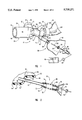
- FIG. 1 is a perspective representation of one multi-access embodiment of the present invention with parts broken away and other parts removed for clarity;
- FIG. 2 is an enlarged fragmentary cross section of FIG. 1;
- FIG. 3 is a fragmentary side elevation of another multi-access embodiment of the present invention.
- FIG. 4 is a longitudinal cross section of one multi-access embodiment of the present invention.
- FIG. 5 is a fragmentary cross section of a modified form of the present invention.
- FIG. 6 is an enlarged fragmentary cross section of one access port of one multi-access apparatus
- FIG. 7 is a fragmentary cross section of FIG. 6;
- FIG. 8 is a fragmentary exploded perspective of another multi-access apparatus
- FIG. 9 is a cross section of the device of FIG. 8;
- FIG. 10 is a fragmentary cross section of another configuration
- FIG. 11 is an enlarged exploded perspective of a rotor valve embodying principles of the present invention.
- FIG. 12 is a side elevation of another multi-access device
- FIG. 13 is a partial exploded perspective of the device of FIG. 12;
- FIG. 14 is a frontal elevation of still another turret configuration
- FIG. 15 is a cross section of still another configuration of a multi-access device
- FIG. 16 is a cross section of a slider valve embodying the principles of the present invention.
- FIG. 17 is a cross section of an additional multi-adapter embodiment of the invention.
- FIGS. 1 and 2 illustrate a multiple access apparatus, generally designated 30, embodying principles in accordance with the present invention.
- Apparatus 30 comprises a T-shaped, elbow-like housing, generally designated 32, an aspirating catheter assembly 34, permanently assembled with the housing 32, and a second catheter assembly, generally designated 36, also permanently connected with the housing 32.
- Elbow fitting 32 comprises a cylindrical wall 38, illustrated as being of uniform thickness and comprising exterior surface 40, interior surface 42, and distal edge 44, which interior surface defines a distal port through which ventilating gases are delivered to the patient, when connected to a tracheal tube, for example.
- Elbow fitting 32 also comprises a proximal port or barrel 46 comprising a hollow interior into which influence ventilating gases are delivered from a suitable commercially available ventilator.
- Barrels 38 and 46 are formed as one piece from a suitable synthetic resinous material.
- the wall 48 comprises a hollow interior defined by an annular interior surface. Wall 48 is preferably of uniform thickness and comprises exterior cylindrical surface 50.
- the hollow interior of barrel 46 receives ventilating gases from a ventilator and is in open communication with the hollow interior defined by surface 42.
- the fitting 32 also comprises a plurality of access ports, one of which is formed by a third (second proximal) barrel 52, the interior of which is also hollow and in direct open communication with the hollow interior formed by wall surface 42.
- a tapered rounded transitional hollow segment 54 connects wall segment 38 with the wall comprising barrel 52.
- the wall forming barrel 52 comprises an exterior surface 56 and an interior surface 58 (FIG. 2) and terminates in a proximal edge 60.
- Edge 60 is radially-directed and annular in its configuration, being interrupted by a notch 62, the diametrical size of which is selected to accommodate positioning of the transverse tube 64 of the attachment 66 of the aspirating catheter assembly 34 therein.
- the structure and use of the aspirating catheter assembly 116 and more particularly the aspirating catheter tube 144 thereof to aspirate secretions from the lungs of a patient is described below.
- an additional access port can be readily provided in adaptor 32. This may be done by boring or otherwise forming an aperture or access port 68 at the step or transition segment 54 of bell housing 38. While aperture 68 is illustrated as being disposed in a particular diagonal orientation, it is to be appreciated that the direction of aperture 68 in transition wall 54 may be selected, as desired, by those skilled in the art.
- the tube 70 having an exterior surface the diameter of which is just slightly smaller than aperture 68 is inserted a desired although short distance into the hollow interior formed by wall surface 42 and is cemented, bonded, plastic welded, or otherwise secured in the inserted position, in the manner typified in FIG. 2.
- the proximal end of the tube 70 is equipped with a female fitting, generally designated 72.
- Fitting 72 comprises a sleeve 74 bonded or otherwise suitably connected to the proximal end of tube 70.
- a bell-shaped housing 76 is secured to the sleeve 74 in telescopic bonded or otherwise non-rotatably secured position such that the enlarged region of bell housing 76 defines a female annular groove 78.
- a second catheter assembly 36 for providing other treatment is permanently placed within recess 78, as explained in greater detail hereinafter.
- Catheter assembly 36 comprises a distal fitting, generally designated 80, a proximal fitting, generally designated 82, and a catheter treatment tube 84 spanning between the two fittings and encapsulated by a collapsible sheath 86.
- Distal fitting 80 comprises a distal collar 88, which is distally tapered to form a reduced diameter tip that is sized, shaped, and dimensioned so as to accommodate being fit into annular slot 78 and bonded or otherwise permanently secured in that position.
- Collar 88 comprises an interior cylindrical surface into which a distal end of the collapsible sheath 86 is extended at the proximal end thereof, as illustrated in FIG. 2.
- a fitting 90 is force-fit into the proximal end of the collar 88, being so dimensioned as to hold the distal end of the collapsible sheath 86 in position against inadvertent removal.
- Fitting 90 comprises a tubular member, which has a uniform cylindrical interior surface throughout. The tubular member comprises an outwardly directed radially-extending flange 92 at the proximal end thereof, the flange 92 having a predetermined diameter at annual periphery.
- a sleeve 94 is force-fit into the proximal end of fitting 90 (FIG. 2) so that the proximal edge thereof is flush with the proximal edge of flange 92.
- the interior surface of sleeve 94 defines a cylindrical passageway diametrically sized so as to snugly receive catheter treatment tube 84 in slidable, wiping relation.
- a cup-shaped friction lock 96 surrounds the catheter treatment tube 84 proximally of fitting 90.
- Lock 96 is preferably cup-shaped with a central aperture that is substantially the same diameter as the outside diameter of catheter tube 84.
- the interior diameter of friction lock 96 is slightly less than the outside diameter of flange 92. Accordingly, when friction lock 96 is advanced over flange 92, the walls of friction lock 96 are biased outward, which creates a pinching or torque action by the central aperture upon the exterior surface of tube 84.
- catheter treatment tube 84 when catheter treatment tube 84 has been advanced into the respiratory tract of the patient the desired distance, the location of the distal end of the catheter treatment tube may be preserved in said inserted position by holding the catheter treatment tube 84 in the desired position through collapsible sheath 86 and, also through collapsible sheath 86 advancing friction lock 96 until it is superimposed over flange 92.
- the pinching action of the central aperture against the exterior surface of the catheter treatment tube 84 will thereafter retain the catheter tube 84 in the predetermined inserted position.
- sleeve 94 can be formed of a compressible material with the outside diameter of sleeve 94 being greater, when unstressed, than the inside diameter of fitting 90.
- the inside diameter of sleeve 94, when unstressed, can be substantially the same as the outside diameter of catheter treatment tube 84.
- the catheter treatment tube 84 is inserted to the desired location in the respiratory tract while the sleeve 94 is in the position of FIG. 1. Once the desired indwelling location is reached, the sleeve 94 is advanced along the catheter tube 84 and compression fit into the hollow interior of fitting 90, thereby stress or compression reducing both the inside and the outside diameters of sleeve 94.
- catheter treatment tube 84 may be unclamped simply by removing sleeve 94 from the hollow bore of fitting 90.
- the proximal fitting 82 of catheter cartridge 36 comprises a female hub having a hollow interior to which oxygen is communication from source 98 when valve 100 is in the open position.
- catheter assembly 36 in lieu of being provided for delivery of oxygen, may be constructed to deliver lavage or medication to the patient or any of the other treatment identified in the summary section of this application including visually inspect selected parts of the respiratory system, to sample sputum and gasses, to sense parameters such as flow rates, pressure and temperature and/or to flush with washing solution as desired using the access site made available by the formation of access port 68 in adaptor 32.
- FIGS. 3 and 4 illustrate a second embodiment of a multi-access apparatus, generally designated 102, for use in conjunction with the respiratory tract of an intubated medical patient ranging from infants to the aged.
- the embodiment shown in FIGS. 3 and 4 has multiples access ports to provide multiple respiratory therapies through catheter assemblies or cartridges, but unlike the embodiment shown in FIGS. 1 and 2, the embodiment illustrated in FIGS. 3 and 4 is designed to have the catheter cartridges removably connected to some of the access ports.
- the apparatus 102 comprises adaptor means for defining a flow path therethrough for delivery of ventilating gases to an intubated patient and for providing an access path for delivery of respiratory therapy to the patient.
- such adaptor means comprises adaptor 104 having a distal port 106, a proximal port 108 and a plurality of access ports 110, 112 and 150.
- distal port 106 and proximal port 108 accommodate continual cyclic patient ventilation, independent of pursuit by the health care provider of any other patient respiratory access procedure.
- Access port 110 accommodates selective insertion and subsequent removal of an aspirating catheter assembly, the catheter tube of which removes secretions from the lungs.
- Access port 112 accommodates releasable attachment and subsequent removal of other catheter means such as an oxygenation catheter assembly, such as oxygenation catheter cartridge 114, the catheter tube of which is used to replace residual carbon dioxide in the lungs with oxygen, or to accommodate entry of temperature or pressure monitoring instruments or to accommodate obtaining samples of sputum or gases and/or to allow insertion of visual inspection instruments. All these catheter assemblies and other instruments are examples of catheter device means for providing respiratory therapy through the adaptor means.
- an oxygenation catheter assembly such as oxygenation catheter cartridge 114
- All these catheter assemblies and other instruments are examples of catheter device means for providing respiratory therapy through the adaptor means.
- the apparatus 102 comprises a tracheal tube adaptor, generally designated 104, preferably formed of injection molded rigid medical grade synthetic resinous material, such as acrylic, cryolite, pebax, polypropylene, or the like.
- Adaptor 104 comprises a distal port 106 formed from a hollow female distal bell housing which comprises a stepped annular wall 116.
- Wall 116 comprises a thickness which is generally uniform. The distal end of wall 116 is defined by a blunt transverse annular distal edge, where the bell housing comprises its largest diameter. Wall 116 comprises a first reduced diameter annular step 118 comprising an inside shoulder, and a second further reduced diameter annular step 120.
- Annular step 120 defines a bifurcation where an annular swivel alignment retaining wall 122 extends distally from the bifurcation with wall 116 adjacent step 120.
- Walls 116 and 122 where co-extensive, are separated by a blind annular slot which opens distally.
- Walls 116 and 122 are illustrated as being formed as one-piece.
- Wall 122 comprises an interior surface, illustrated as being of uniform diameter, an exterior surface and a blunt annular transverse distal edge.
- Wall 62 is stepped or notched at shoulder 124.
- Adaptor 104 also comprises a proximal port 108 formed from a second bell housing which is constructed to comprise components the same as the bell housing forming distal port 106, although the bell housing forming proximal port 108 is somewhat shorter in its axial length. Accordingly, the parts of the two bell housings have been enumerated the same and no further description is needed for one skilled in the art.
- embodiments may comprise sleeve means for providing a swivel coupling for joining the adaptor means to the ventilator tubing and the intubated patient.
- sleeve means comprises sleeve 126 and sleeve 128.
- Sleeve 126 is rotatably positioned and secured within the bell housing forming distal port 106.
- Sleeve 126 comprises an annular wall 130 comprising an interior surface, which is generally annular, but may be slightly divergently tapered from left to right, as viewed in FIG.
- Sleeve 126 also comprises a predetermined length between blunt edges 132 and 134.
- Edge 132 is radially flush with the outer edge of the bell housing forming distal port 106.
- Edge 134 rotatably abuts notch 124.
- Sleeve 126 also comprises an outwardly directed radially extending retaining flange 136.
- the location of flange 136 is selected to be adjacent step 118 to accommodate rotation contiguous with the inside of step 118.
- Sleeve 126 also comprises a relatively thin integral delectably yieldable annular sealing rib or finger 138. Rib 138 extends proximally in an axial direction.
- the sealing rib 138 is caused to forcibly engage a surface within the annular slot formed by walls 116 and 122 and be deflected into a firm sealed relation with that surface to thereby hermetically close the interface between sleeve 126 and the bell housing.
- Sleeve 126 is retained in the position illustrated in FIG. 4 by an annular rigid plastic collar 140 positioned between walls 116 and 130. Collar 140 is bonded to the surface of wall 116. Thus, collar 140 functions as a bushing with flange 136 and the surface of sleeve 126 contiguously but rotatably engaging the proximal edge and inside annular surface of collar 140.
- Sleeve 128 is enumerated identical to sleeve 126 although it will be readily apparent that the sleeve orientation is reversed, the overall length of sleeve 126 is shorter, the sleeve 128 extends beyond the bell housing and the radial flange 136 is positioned closer to the blind slot formed by wails 116 and 122.
- Ventilating tubing is compression fit into or over the exposed part of sleeve 128.
- a tracheal fitting is inserted into the hollow of sleeve 128.
- Sleeve 128 rotates with any rotation imposed upon the connected ventilating tubing or, alternatively, retain an essentially stationary position if and when the adaptor 104 is rotated, either intentionally or inadvertently in respect to sleeves 126 and 128.
- twisting and consequential occluding or partial occluding of ventilating tubing is avoided.
- Adaptor 104 further comprises an angularly-disposed proximally-directed barrel, generally designated 142 forming access port 110.
- Proximally-directed barrel 142 comprises an annular wall, the exterior surface of which is annular, while the interior surface is illustrated as being slightly tapered divergently in a distal direction to receive, in compression-fit relation, an aspirating catheter cartridge, generally designated 34.
- Cartridge 34 will be explained in greater detail hereinafter.
- the interior surface of barrel 142 defines a proximal passageway or access port 110, the diametrical size of which is substantially smaller than either of the two previously described passageways, distal port 106 and proximal port 108.
- Access port 110 provides a pathway through adaptor 104. It should be noted that the longitudinal axis of distal port 106 and the longitudinal access of access port 110 intersect each other at a relatively small acute angle, which may be on the order of about 20°, to accommodate ease of insertion and centering of a slidable aspirating catheter tube 144, forming part of the aspirating catheter cartridge 34.
- Catheter tube 144 is flexible along its length to accommodate smooth insertion through a tracheal tube, for example, into either lung of the patient for removal of secretions.
- Barrel 142 is preferably formed as one piece with the other components of adaptor 104, excluding swivel sleeves 126 and 128.
- Adaptor 104 further comprises a second angularly-disposed proximally-directed barrel, generally designated 146 forming a second access port 112.
- Barrel 146 comprises an exterior substantially cylindrical surface, and interior surface which is illustrated as being slightly divergently tapered in a distal direction, for purposes yet to be explained. Barrel 146 terminates in a proximal edge, which is blunt and transversely-directed. Barrel 146 comprises a wall of uniform thickness defining access port 112, which merges distally with distal port 106, forming a small acute angle therewith on the order of about 20°, as illustrated in FIG. 4, although other angles could be used.
- Barrel 146 is interrupted by a male transversely directed side port tube 148, the hollow interior of which defines access port 150.
- the tube 148 comprises a smooth interior annular surface, illustrated as being of uniform diameter and an exterior surface, which is interrupted by an outwardly-projecting radially-directed annular barb, by which a medication-administering attachment, generally designated 66, is secured against inadvertent removal.
- Barrel 146 comprises part of the one-piece construction of adaptor 104; as illustrated in FIG. 4.
- Barrel 146 is illustrated in FIG. 4 as being closed by a tethered, press-fit cap, generally designated 152.
- Cap 152 is sized and shaped so as to be snugly received in the position illustrated in FIG. 4, somewhat compressively, so that inadvertent removal does not take place.
- Cap 152 is formed, as illustrated, of one piece comprising an annular collar, a plug, and a tether, which connects the collar to the plug.
- the collar of cap 152 is generally annular in its configuration, comprising wall defined by an inside annular surface, the diameter of which is slightly smaller than the diameter of the exterior surface at the proximal end of barrel 146, so that the collar must be force-fit into the position illustrated in FIG. 4 and remains in the illustrated position unless intentionally manually removed.
- the plug of cap 152 fits snugly inside a hole in cap 152 to prevent inadvertent removal of the plug.
- the hole of cap 152 may be substantially smaller than the inside diameter of barrel 146 in order to provide a tight seal against accessory devices placed through access port 112.
- cap 152 By closing the access port 112 with the plug of cap 152, introduction of microbes and other undesired contamination is prevented. Yet, the cap 152 can be quickly and easily manually removed to accommodate introduction through access port 112 of medication, an oxygenation catheter tube, monitoring devices, sampling devices, and visual inspection, instruments, etc.
- the attachment 66 connected to side port tube 148, comprises a distal fitting, generally designated 154, which is L-shaped in configuration, as illustrated.
- a distal fitting generally designated 154
- One end of distal fitting 154 is force-fit over side port tube 148 and held in place by the barb on tube 148 as illustrated in FIG. 4.
- the other end of distal fitting 154 is attached to tube 156 either in a compression fit relation, or so as to be bonded or plastic welded in position.
- Tube 156 may be of any desired length.
- Attachment 66 comprises, in addition, a proximal fitting, generally designated 158.
- Proximal fitting 158 is attached to the proximal end of tube 156, either by force-fit or secured as by plastic welding, bonding, or the like.
- Proximal fitting 158 may be closed by cap 160 as shown in FIGS. 3 and 4.
- Cap 160 is preferably sized and shaped so that cap 160 can be manually removed when desired, but will not inadvertently separate From proximal fitting 158. Also as shown in FIGS. 3 and 4 cap 160 may be attached to proximal fitting 158 with a tether.
- Proximal fitting 158 may have a cylindrically shaped slit valve, generally designated 162, disposed therein.
- slit valve 162 is generally I-shaped, as seen in FIG. 4, and comprises an end-to-end length substantially equal to the interior length of proximal fitting 158.
- Slit valve 162 may be formed of silicone rubber, KRATONTM, or the like, and comprises an annular wall of uniform thickness throughout, as illustrated, comprising an external surface, an internal surface, as well as blunt transversely disposed distal and proximal edges.
- a contoured radially-directed double dome-shaped central wall or diaphragm 164 expands across and normally closes the space within proximal fitting 158.
- Web or wall or diaphragm 164 is necked down at the annular site where diaphragm 164 joins the wall of slit valve 162, as one piece, making the annular site the weakest part of diaphragm 164, exclusive of one or more central slits.
- the central slit may be of any desired size so as to be capable of receiving a hollow male end of an instrument therethrough, which may be utilized to serve any number of purposes.
- respiratory medication may be applied through a hollow male projection physically inserted through the central slit, through which the medication may be dispensed under aerosol pressure or by manual pressure, for example.
- the central slit is illustrated as being located both at the center of the slit valve 162 and in the region of greatest thickness of diaphragm 164.
- the double domed configuration of the diaphragm 164, with the enlarged lips at the slit enhances a return to the normally closed state upon removal of the male projection.
- fluid introduced through slit valve 162 will enter adaptor 104 through fluid introduction port 150.
- a slit valve may be placed directly in barrel 146, as illustrated in FIG. 5. More specifically, the wall of barrel 146 in FIG. 6 is equipped with a liquid introduction port 150 of pre-determined size.
- Slit valve 166 is illustrated as comprising an enlarged annular flange disposed external of the outside surface of barrel 146, to prevent displacement of the entire slit valve 166 into the interior of barrel 146 when forcibly engaged by hollow male projection of a medication or saline dispenser or container 168.
- Catheter cartridge 34 comprises the mentioned aspirating catheter tube 144, illustrated as being of uniform thickness and inside and outside diameter throughout, and a distal fitting 170.
- Fitting 170 comprises a slightly tapered distally-directed projection 172, shown as being in spaced relation to and telescopic surrounding catheter tube 144, catheter tube 144 being illustrated in FIG. 4 in a withdrawn state.
- a space or wash chamber 174 exists between the exterior surface of the catheter tube 144 and the interior surface of projection 172. As explained hereafter, the wash chamber allows the exterior of catheter tube 144 to be cleaned or washed.
- Projection 172 distally merges with an inwardly-directed transverse or radial flange formed as one piece with projection 172.
- This inwardly-directed annular flange has a central circular opening through which tube 144 contiguously though slidably extends and as shown hereafter limits the passage of wash solution into the respiratory tract of a patient.
- Projection 172 has formed therein access port 150, which is aligned with the hollow interior of a transverse, relatively short hollow male projection or tube 178.
- Tube 178 is formed as one piece with projection 172. Excluding length, hollow tube 178 is constructed substantially identical to the construction of hollow tube 148 and is correspondingly enumerated. No further description is necessary to impart an understanding to one of skill in the art.
- the hollow tube 178 is connected to a second attachment 66, which is constructed identical to previously described attachment 66 and is so enumerated in FIG. 4.
- the attachment 66 of the aspirating catheter cartridge 34 may be used to wash the exterior and interior surfaces of the catheter tube after it is withdrawn from the patient, saline or other suitable wash solution being introduced by a hollow male projection extended through slit valve 162 and thence along the hollow interior of attachment 66 of catheter cartridge 34 through fluid introduction port 176 into wash chamber 174.
- the inwardly-directed flange at the end of projection 172 limits passing of the wash solution into adaptor 101 and from thence into the respiratory tract of the patient.
- Used wash solution is evacuated through the hollow of the catheter tube 144 due to suction applied there.
- lavage may be introduced through attachment 66, in the manner explained above, when the catheter tube 144 is fully or partially inserted into the respiratory tract, which lavage runs slowly down the catheter tube into the respiratory tract.
- the distal fitting 170 comprises an annular seal or washer 180 which seals around catheter tube 144.
- the seal or washer 180 is preferably formed of yieldable synthetic resinous material, such as silicone rubber, and has an inside diameter that compressively engages the exterior surface of the catheter tube 144.
- the catheter tube 120 is wiped by seal 180 as it is withdrawn from use in the respiratory system of an intubated medical patient, thereby removing secretions and other materials carried upon the exterior surface of the catheter tube 144 and depositing the same in the wash chamber 174.
- Collar 182 has a double flange configuration which provides a certain amount of radially compressibility, which accommodates ready compression fit insertion within the rest of distal fitting 170 with the forward edges of collar 182 holding seal 180 in the illustrated position of FIG. 4. Collar 182 also provides guidance to the catheter tube as it is displaced.
- a collapsible, preferably transparent, plastic sheath generally designated 184 is placed over the trailing outside annular surface of collar 182.
- the end of sheath 184 is held in compression-fit relationship by a ring 186 forced over the end of sheath 184 and collar 182.
- FIG. 3 illustrates the proximal end of the aspirating catheter cartridge 34.
- the proximal end of the cartridge 34 comprises seriatim a proximal fitting 188 disposed at the end of the collapsible sleeve or envelope 184, a normally closed valve means such as suction valve 190 and an exteriorally stepped tube, generally designated 192.
- Fitting 188 is illustrated as being formed as one piece from suitable synthetic resinous material and is secured to suction valve 190 by plastic welding, bonding, or any other suitable fashion.
- Oxygenation catheter cartridge 114 comprises a distal fitting 194. With a hollow male projection 196 through which a hollow oxygenation catheter treatment tube 198 can be manually advanced and retracted into and from a suitable lung position for the purpose of oxygenating and potentially replacing residual carbon dioxide within the selected lung with oxygen.
- the catheter treatment tube 198 is surrounded by a sheath 200 which is similar in structure and function previously described sheath 184. The distal end of the sheath 200 is attached to distal fitting 194.
- Oxygenation catheter cartridge 114 comprises a proximal fitting 202 which is attached to the proximal end of the sheath 200.
- the proximal fitting 202 is centrally hollow and is in fluid communication with the hollow interior of catheter treatment tube 198.
- valve 204 is manually opened, causing oxygen from source 206 to be delivered at a suitable rate and pressure to the selected lung site.
- cartridge 114 When utilization of the oxygenation cartridge 114 is over (with the catheter tube 198 retracted) cartridge 114 is removed. Another unused oxygenation catheter cartridge of the same or similar construction could be used later when oxygenation is desired. The same approach is true of cartridge 34, i.e., it can be replaced after one or more uses to prevent undesired risks to the patient due to growth of micro-organisms therein with the passage of time. While the configuration of FIGS.
- Access port 112 can also be utilized to directly receive lavage and/or medication as illustrated in FIGS. 6 and 7, to which reference is now made.
- a one-piece duck bill valve generally designated 208, is illustrated as being compression-fit into the proximal or trailing end of barrel 146.
- Duck bill valve 208 is adapted to receive a lavage or medication receptacle 168, a male projection comprising any of the inserted items described in this specification, being illustrated in FIG. 7 as exemplary.
- the diameter of duck bill valve 208 is slightly greater than the interior of barrel 146.
- the duck bill valve 208 is made of a suitable synthetic material with memory, which is substantially yieldable.
- valve 208 is formed of one piece from a suitable elastomeric synthetic resinous material, such as silicone rubber.
- a suitable elastomeric synthetic resinous material such as silicone rubber.
- the nature of the construction of valve 208 is such that access port 112 is normally closed by valve 208.
- lavage or medication held in container 168 can be introduced into access port 112 and from thence into the respiratory of the intubated medical patient by causing a hollow male projection of container 168 to be inserted through valve 208.
- container 168 and its male projection are intended to be illustrative and not restrictive.
- container 168 can be an aerosol container or a container which can be manually collapsed to discharge the appropriate amount of medication or lavage dose.
- container 168 is sized so as to be snugly received within the hollow defined by valve 208.
- Catheters, probes, and other instruments can also be inserted through valve 208 to accommodate samples, monitoring, inspection, and various forms of respiratory therapy as described in the summary section of this application.
- FIGS. 8 and 9 illustrate another multi-access assembly, generally designated 210, for use in conjunction with the respiratory tract of an intubated medical patient ranging from infants to the aged.
- Assembly 210 comprises an adaptor means for defining a flow path therethrough for delivery of ventilating gasses to an intubated patient and for providing an access path for delivery to the intubated patient such as elbow type connector, manifold, fitting, or adaptor, generally designated 212.
- Adaptor 212 comprises a distal port 214, a proximal port 216, a plurality of access ports 218, 220 and 222.
- distal port 214 and proximal port 216 accommodate continual cyclic patient ventilation, independent of implementation by the health care provider of any other patient respiratory access procedure.
- Access port 222 accommodates introduction of irrigation or wash liquid by which the exterior of an aspirating catheter tube, for example, is washed as the catheter tube is withdrawn following use. Port 222 also accommodates delivery of lavage to the interior of adaptor 212.
- Access ports 218 and 220 accommodate access by an accessory device, such as but not limited to selective insertion and subsequent removal of an aspirating catheter assembly, the catheter tube of which removes secretions from the lungs.
- Access ports 218 and 220 also accommodate an oxygenation catheter assembly, the catheter tube of which is used in the lungs to replace residual carbon dioxide with oxygen, and/or entry of temperature or pressure monitoring instruments or obtaining samples of sputum or gases and/or to allow insertion of visual inspection instruments.
- access ports 218 and 220 can accommodate any of the catheter means in this application.
- the adaptor 212 comprises a distal tracheal tube bell housing connector, generally designated 224, preferably formed of injection molded rigid medical grade synthetic resinous material, such as acrylic, cryolite, pebax, polypropylene, or the like.
- Connector 224 comprises a stepped annular wall 226.
- Wall 226 comprises a thickness which is variable and stepped, defined by inside and outside surfaces.
- the distal end of wall 226 is defined by a blunt transverse annular distal edge, where the bell housing 224 comprises its largest outside diameter.
- Wall 226 comprises a first reduced diameter exterior annular rounded step or shoulder and a second further reduced diameter exterior annular rounded step or shoulder.
- an interior shoulder or stop 228, which limits the amount swivel sleeve 230 can be inserted inside bell housing 224.
- the interior surface of wall 226 comprises an annular shoulder 232, which accommodates rotation of swivel sleeve 230 while preventing axial displacement thereof.
- Adaptor 212 also comprises a second bell housing, generally designated 234, in which proximal port 216 is formed and which is constructed to comprise components similar to bell housing 224, although bell housing 234 is substantially shorter in its axial length. Bell housing 234 is illustrated as being disposed at 90° to bell housing 224.
- Bell housing 234 comprises an annular wall 236.
- Wall 236 comprises a thickness which is variable and stepped, defined by inside and outside surfaces.
- the distal end of wall 236 is defined by a blunt transverse annular distal edge, where the bell housing 236 comprises its largest outside diameter.
- Wall 236 comprises a reduced diameter exterior annular rounded step or shoulder 238. Shoulder 238 is also interiorly rounded.
- the interior surface of wall 236 comprises an annular shoulder 240, which accommodates rotation of swivel sleeve 242, while also limiting the extent to which swivel sleeve 242 is capable of being axially inserted into the bell housing 234.
- Sleeve 230 When fully assembled, sleeve 230 is rotatably positioned and secured within the bell housing 224.
- Sleeve 230 comprises a generally annular wall comprising an interior surface, which is generally annular, but may be slightly divergently tapered from left to right, as viewed in FIGS. 8 and 9, to accommodate a press-fit but removable union with a proximal fitting of a tracheal tube, for example, in a manner well-known to those skilled in the art.
- Sleeve 230 also comprises a predetermined length so as to fit flush within bell housing 224.
- Sleeve 230 comprises an outwardly-directed radially-extending retaining annular flange or boss 244.
- the location of flange 244 is selected to be adjacent to step or shoulder 232 to accommodate axial rotation contiguous with shoulder 232.
- Sleeve 230 is retained in the position illustrated in FIG. 9 by an annular rigid plastic collar 246.
- Collar 246 is bonded to the inside surface of wall 226 in the position illustrated in FIG. 9.
- collar 246 functions as a stationary bushing with flange 244 of sleeve 230 to contiguously but rotatably engaging the inside edge surface and inside annular surface of collar 246.
- Sleeve 242 which is rotatably coupled to bell housing 234, is substantially similar to sleeve 230, being rotatably placed within bell housing 234.
- Sleeve 242 is enumerated identical to sleeve 230, although it will be readily apparent that the sleeve orientation is reversed, the thickness of sleeve 230 is less than the thickness of the sleeve 242, sleeve 242 extends beyond bell housing 234 and the radial flange 244 is positioned closer to the edge of sleeve 242.
- Ventilating tubing is conventionally compression fit over the exposed surface of sleeve 242.
- a tracheal fitting as stated above, is inserted into the hollow interior of sleeve 230, to complete the ventilating circuit.
- Sleeve 242 rotates with any rotation imposed upon the connected ventilating tubing or, alternatively, retain an essentially stationary position if and when the adaptor 212 is rotated, either intentionally or inadvertently, in respect to sleeves 230 and 242. Thus, twisting and consequential occluding or partial occluding of ventilating tubing is avoided.
- the bell housings 224 and 234 integrally merge with an L-shaped segment, to provide an L-shaped passageway through the adaptor 212.
- the L-shaped segment merges into two cylindrical wall segments 248 and 250, which respectively define proximal access pathway 252 and access port 222.
- Pathway 252 is sized and shaped so as to accommodate access by any of the previously mentioned accessory devices.
- Port 222 accommodates selective passage of irrigating liquid and/or lavage.
- Wall 250 is annular, diametrally relatively small and centrally hollow. Wall 250 receives, in force-fit relation, one leg of an L-shaped elbow of an irrigation or lavage delivery system, generally designated 66.
- System 66 comprises a hollow tube 156 which extends into and is secured within a leg of elbow 154, a proximal fitting 158, a proximal cap 160, and a tether securing the cap against loss when it is disconnected from fitting 158.
- the hollow interior of wall 248 is unobstructed and diametrically smaller than the diameter of either port 214 or port 216, but larger than port 222, port 216 being diametrally smaller than port 214.
- the assembly 210 comprises access control means such as a turret valve, generally designated 264.
- Turret valve 264 comprises a stator, generally designated 266, and a rotor, generally designated 268.
- the stator 266 comprises a flat stationary plate, which is formed as one piece with both a support flange 270 and wall 248. The intersection between wall 248 and the flat plate defines the proximal opening of pathway 252.
- the rotor 268 comprises an annular inwardly-directed radial lip 272, which is force-fit over and is selectively rotatable in respect to stator plate 266 to create the assembly illustrated in FIGS. 8 and 9.
- the relationship between the peripheral edge of the stator and the lip 272 comprises a guide, track or cam/cam follower.
- the rotor 268 can be manually turned in respect to the stationary stator plate 266, to an extent and for purposes yet to be explained.
- the rotation is limited, in the illustrated embodiment, to approximately 180°.
- the rotor 268 comprises means to limit the rotation of the turret valve such as outwardly-extending stops 274 and 276 which are sized, shaped, and positioned so as to have a diameter which will cause engagement with stop cantilevered finger 278 of stator 266 when rotor 264 is rotated.
- the stop 278 allows but limits rotation of the rotor 264 until either stop 274 or stop 276 makes contact therewith. Accordingly, when viewed from the right in FIG. 8, clockwise rotation of the rotor 264 will bring the stop 276 into contact with stop finger 278, whereas counter-clockwise rotation of the rotor 264 will bring the stop 274 into contiguous contact with stop finger 278.
- the rotor base plate 280 comprises two apertures formed therein and two tubes 282 and 284 sized and shaped so that the distal ends thereof fit snugly into and are permanently secured therein by any suitable technique. While tubes 282 and 284 are shown as being initially formed separate from the rotor base 280, they could be formed as one piece with rotor base 282 using conventional injection molding techniques. Tubes 282 and 284 define access port 218 and 220, respectively.
- a pair of O-rings 286 and 288 are compressively positioned between the distal end of tubes 282 and 284 and the stator base plate so as to prevent leakage at that location.
- the O-rings 286 and 288 have a diametral size slightly greater than the diametral size of pathway 252 and the diametral size of access ports 218 and 220.
- Tubes 282 and 284 may be slightly angular one to another, to prevent interference.
- Tube 282 also comprises an external annular groove 290 into which a radially stretched tether ring of cap 292 is placed and thereafter contracted so that the tether ring, in the assembled position, exerts a compressive force upon the base of groove 290.
- Cap 292 comprises a central aperture that can be closed by plug 294 which has a diameter that is slightly greater than the diameter of the central aperture so that full insertion of plug 294 into the aperture diametrally enlarges or stretches the aperture to create a compression-fit, sealed relation.
- Plug 294 can be manually pulled or pried from the central aperture, to accommodate subsequent insertion of an accessory device through the aperture.
- a tether prevents misplacement of the plug 294.
- Cap 292 can also be manually removed from the position illustrated in FIG. 9 at the proximal end of tube 282, to accommodate placement of any desired accessory device directly into access port 218, without passage through the smaller central aperture of cap 292.
- the tether ring in groove 290 prevents loss of either or both the cap 292 and the plug 294.
- rotor 264 is selectively manually rotated from the position of FIG. 8 to a position about 180° out of phase with the position of FIG. 8, where tube 282 is located out of alignment with pathway 252 and tube 284 is in alignment with pathway 252. As this rotational displacement occurs, O-ring 286, at its distal contact with the flat stator plate simply sealingly slides therealong from the aligned to the non-aligned position.
- Tubes 282 and 284 define access ports 218 and 220, into which the distal end of certain accessory devices can be inserted.
- these accessory devices or catheter means are used to aspirate secretions from the lungs and provide other treatment such as to oxygenate the lungs to eliminate or reduce residual CO 2 therefrom, to visually inspect selected parts of the respiratory system, to sample sputum and gasses, to sense parameters such as flow rates, pressure, and temperature, to flush with washing solution, and/or administer medication, gasses, and/or lavage.
- a distal fitting 296 is illustrated as being press-fit into access port 220. The press-fit relationship can be manually overcome when desired.
- Distal fitting 296 is illustrated as being part of an aspirating catheter assembly, generally designated 298, which also comprises an aspirating catheter tube 300 around which a collapsible sheath or envelope 302 is positioned.
- catheter tube 300 When access port 220 is aligned with pathway 252, in the manner explained above, the health care provider can thereafter conventionally insert catheter tube 300 into the respiratory tract of the patient to remove secretions and the like in a well-known fashion. While aspirating catheter assembly 298 is illustrated as being an accessory device positioned in tube 284, it is to be appreciated that accessory devices other than an aspirating catheter assembly can be used in conjunction with access port 220.
- Aspirating catheter cartridge 298 is similar to aspirating catheter cartridges previously described except that catheter cartridge 298 does not have a lavage assembly. Since the embodiments illustrated in FIGS. 8 and 9 have lavage assembly 66 attached to adaptor 212, the individual accessory devices do not need to have individual lavage assemblies. Other than this difference, construction and operation of catheter cartridge 298 is similar to other aspirating catheter cartridges previously described.
- FIG. 10 illustrates an additional multi-access respiratory apparatus, generally designated 304, embodying principles of the present invention.
- Apparatus 304 comprises an accessory device 306, a Y-adaptor, generally designated 308, comprising access control means such as turret assembly 310.
- Adaptor 308 comprises a distal port 312 defined by distal hollow tubular tip member 314, adapted to be force-fit into a port-defining opening in a tracheal fitting or into a fittingless exposed proximal end of an indwelling tracheal tube, which also accommodates patient ventilation.
- the tip 314 is tapered at its end to accommodate such insertion, while its exterior cylindrical wall surface accommodates a compression fit.
- Adaptor 308 also comprises a proximal port 316 adapted to accommodate introduction and exhaustion of ventilating gases.
- the access passage 318 defined by wall 320 is adapted to accommodate access to the interior of Y-adaptor 308 by any one of several accessory devices such as device 306.
- enlarged cylindrical or annular wall 320 is illustrated as sized to accommodate access of an accessory device.
- Barrel 320 merges as one piece with a stator plate 322 forming a part of access control device 310.
- Stator plate 322 is substantially identical to previously described stator plate 266 of FIGS. 8 and 9.
- Control device 310 is substantially identical to previously described turret valve 264 of FIGS. 8 and 9, except stops 274 and 276 have been eliminated.
- the components of control device 3210 have otherwise been enumerated identical to the above-described components of valve 264 of FIGS. 8 and 9 to indicate identity or substantial identity and no further description of these components is required for those skilled in the art.
- stator plate 322 may comprise a male edge stop projection 324, which is eccentric to the plate 322 and is placed in a female 180° slot or groove 326 of the flange of the rotor 268. Each end of the groove 326 comprises a blunt abutment surface or stop shoulder 328 and 330.
- Either stop 328 or 330 can, by rotation of rotor 268 be placed contiguous with the male stop 324 to align the interior of either tube 282 or tube 284 with the passageway 318.
- the peripheral edge of plate 322 is snap-fit into blind guide groove 332, to provide aligned rotor rotation.
- FIGS. 12 and 13 illustrate a further multi-access manifold, fitting, or adaptor, generally designated 334 comprising access control means such as access control device 336, which is in the nature of a turret valve having only one passageway through the rotor thereof for alignment and misalignment of a proximal access port of the manifold 334 to accommodate access to the interior of the manifold 334 by an accessory device through the control device 336.
- access control device 336 is in the nature of a turret valve having only one passageway through the rotor thereof for alignment and misalignment of a proximal access port of the manifold 334 to accommodate access to the interior of the manifold 334 by an accessory device through the control device 336.
- Adaptor 334 is substantially the same as adaptor 104 of FIGS. 3 and 4 with the exception that access port 110 is capped by cap 292, adaptor 334 has access control means for providing selective access through the adaptor, such as access control device 336, and adaptor 334 has been modified to include a lavage delivery system 66.
- Control device 336 comprises a turret valve, certain components of which are the same, and so numbered in FIGS. 12 and 13, as previously described in respect to turret valve 264, except as otherwise specified herein.
- O-ring 288, tube 284, and the external stops 274, 276 and 278 have been eliminated.
- Internal stops 328 and 330 are used.
- turret valve 336 provides only a single or registered enabled position, i.e., where port 110 thereof is substantially aligned with barrel 338, which provides a pathway for accessory devices.
- Barrel 338 is illustrated as being equipped with the previously described lavage/irrigation delivery system 66.
- FIG. 14 depicts only a rotor portion, generally designated 340, of a turret valve control device, which also comprises a stator plate of the type heretofore described.
- Rotor 340 comprises the previously described plate or base plate 280 and lip 272.
- Plate 280 of FIG. 14 comprises three ports or passageways around which O-ring seals 286, 288, and 342 are respectively compressively situated for the same purpose described above.
- any desired one of the three access ports can be enabled or placed in registry with an access path of an associated connector, fitting, manifold or adaptor, while at the same time the other two access ports are disabled. Any such enabled access port accommodates communication into the manifold, fitting or adaptor by a desired accessory device. Any access port in a disabled or non-registered position can accommodate attachment and detachment of a desired accessory device at that site.
- FIG. 15 illustrates a further manifold, generally designated 344, which is in the form of an elbow fitting.
- the features and components of elbow 344 duplicate a substantial number of the features and components of previously described elbow 212 to the extent FIG. 15 is correspondingly enumerated.
- Elbow 344 differs from elbow 212 in the ways described below. Tubes 282 and 284 have been replaced by access ports 372 and 374 formed in rotor 370, access pathway 252 has been replaced by port 348, and access port 222 has been replaced by access port 350. Swivel sleeves for ports 214 and 216 are not shown for ease of illustration and description.
- the hollow L-shaped corner of adaptor 344 is defined primarily by two generally cylindrical or annular walls 354 and 356.
- Walls 354 and 356 each comprise an annular segment 358 which cantilevers into ports 214 and 216, respectively.
- a longitudinally-directed cantilevered ring 360 is disposed in concentric relationship between wall 226 and the adjacent segment 358 and between wall 236 and the adjacent segment 358.
- two spaced parallel annular blind grooves 362 are formed on opposite sides of each ring 360. These blind grooves 362 are designed to receive spaced sealing elements of a swivel sleeve when inserted into each of ports 214 and 216, respectively.
- Adaptor 344 has been provided with a further medication port 352.
- Medication port 352 opens into the hollow interior of the adaptor 430, adjacent to diagonal baffle 364, by which medication delivered to port 352 is deflected toward the hollow interior of adaptor 344 toward the corner to enhance delivery, in an atomized form, to the patient, using ventilating gases as a carrier.
- Lavage and/or irrigation liquid can selectively be delivered through port 350, for example, in the manner described above. Where port 352 is used for medication, use of port 350 can be limited to irrigation, if desired.
- Adaptor 344 comprises access control means such as access control device 366.
- Access control device 366 comprises stator flange 368.
- control device 366 comprises a rotor, generally designated 370.
- Rotor 370 comprises a body of material which defines angularly disposed access ports 372 and 374. By manually rotating rotor 370, either port 372 or port 374 is principally placed in registry with distal port 214. The registry position of port 374 is shown in FIG. 15.
- An accessory device can be received at either or both access ports 372 and 374, a distal fitting 376 of an accessory device being illustrated in FIG. 15 as compression-fit into port 374, for illustrative purposes.
- Either or both ports 372 and 374 can be temporarily plugged, capped, or closed in any suitable way, such as is explained above.
- O-ring 378 is compressively interposed between stator flange 368 and rotor 370 slightly beyond the diametral limits of port 348.
- the O-ring seal 378 accommodates rotation of rotor 370 to align either port 372 or port 374 with distal port 214, while preserving its sealing relation.
- Access control device 380 comprises a slider valve by which any one of a plurality of access ports can be enable& i.e., aligned or placed in registry with a single access pathway.
- Slider valve 380 comprises stator element, generally designated 382, and slider element, generally designated 384.
- Stator 382 comprises a flat elongated plate 386, illustrated as being of uniform thickness throughout.
- Plate 386 comprises two parallel side edges along which the slider element slides back and forth.
- Single port stator plate 386 is centrally interrupted by a single circular aperture 3880
- Plate 386 merges as one piece with a distal cantilever tube 390, the cylindrical hollow interior of which is aligned with and of the same diametral size as aperture 388.
- Tube 390 is adapted to be compression-fit to a proximal access port of a connector, manifold, fitting, or adaptor.
- Dual port slider 384 comprises a flat rectangular plate 392, which comprises two parallel edges that slide along the parallel edges of stator plate 386.
- Plate 392 is illustrated as being of uniform thickness.
- Spaced openings 394 exist through plate 392.
- a rounded seat is provided in the surface of plate 392 around each opening 394 to receive an O-rings 396.
- a cylinder 398 surrounds each opening 394.
- the tapered interiors of the cylinders 398 accommodate compression-fit insertion and removal of a distal fitting of an accessory device.
- Cylinders 398 can be closed, capped, plugged, or the like when not in use.
- the plate 392 merges as one piece, top and bottom, with a channel-shaped edge 400 connected to the top of the plate, at a 90° angle thereto.
- Channel-shaped edge 400 forms a U-shaped groove.
- the width of the groove is just slightly greater than the thickness of plate 386 so that when plate 386 is placed within the groove slider 384 can be displaced back and forth within the groove, which serve as tracks or guides for such displacement.
- each O-ring 396 When assembled, each O-ring 396 is compressed between the associated seat and plate 386 to seal the associated port 394. Both O-rings 396 slide back and forth with slider 384, while retaining their respective sealed relation between their respective seats and plate 386.
- a pair of bars 402 if desired, can be integrally connected to slider 384 and span underneath plate 386 of stator 382 at spaced locations such that contact between one bar 402 and the tube 390 will align one access port 394 with port 388, while contact between the other bar 402 and the tube 390 will align the other access port 394 with port 388.
- either access port 394 can be enabled or placed in registry for communication of an accessory device to the interior of an associated manifold, for example, via aligned access ports 394 and 388.
- the non-aligned access port 394 is disabled, allowing for attachment and/or detachment of a selected accessory device at the disabled access port 394.
- FIG. 17 illustrates an additional mariner in which the number of access ports available to the respiratory tract of an intubated medical patient can be enlarged through use in tandem of an elbow and a multiple port Y adaptor generally designated 396. More specifically, the multiple access apparatus of FIG. 17 is illustrated as comprising an elbow adaptor 398 and the second adaptor 396, which comprises an adaptation of adaptor 104 illustrated in FIGS. 3 and 4 and described earlier.
- Elbow adaptor 398 forms a removable coupling to the tracheal tube of an intubated patient and is more fully described in copending application Ser. No. 08/591,950 previously incorporated by reference.
- Also illustrated in copending application Ser. No. 08/591,950 are other adaptors which form a removable coupling to the tracheal tube of an intubated patient and which can also be used in conjunction with Y adaptor 396.
- Adaptor 396 eliminates the proximal swivel connector, replacing it with the solid wall closing proximal port 108 and also eliminates the distal swivel connector. Otherwise, adaptor 396 is constructed and functions as heretofore described in respect to adaptor 104 and is so enumerated in FIG. 17. No further description is necessary, other than to point out that ventilation occurs in the apparatus of FIG. 17 through elbow adapter 398, making elimination of the swivel connectors feasible and advisable.
- Cylindrical wall 122 is sized and constructed so as to comprise a distal edge and to present a diameter which accommodates a press-fit union against the interior surface of cylindrical wall 400. Accordingly, the single proximal access port defined by cylindrical wall 400 is, in effect, increased two-fold by utilization of adapter 396, which provides access ports 110 and 112 as explained earlier.
Abstract
Description
Claims (38)
Priority Applications (1)
| Application Number | Priority Date | Filing Date | Title |
|---|---|---|---|
| US08/653,938 US5735271A (en) | 1994-05-18 | 1996-05-22 | Multiple access adaptors for monitoring, sampling, medicating, aspirating, and ventilating the respiratory tract of a patient |
Applications Claiming Priority (4)
| Application Number | Priority Date | Filing Date | Title |
|---|---|---|---|
| US24533394A | 1994-05-18 | 1994-05-18 | |
| US39535195A | 1995-02-28 | 1995-02-28 | |
| US59195096A | 1996-01-23 | 1996-01-23 | |
| US08/653,938 US5735271A (en) | 1994-05-18 | 1996-05-22 | Multiple access adaptors for monitoring, sampling, medicating, aspirating, and ventilating the respiratory tract of a patient |
Related Parent Applications (2)
| Application Number | Title | Priority Date | Filing Date |
|---|---|---|---|
| US39535195A Continuation | 1994-05-18 | 1995-02-28 | |
| US59195096A Continuation | 1994-05-18 | 1996-01-23 |
Publications (1)
| Publication Number | Publication Date |
|---|---|
| US5735271A true US5735271A (en) | 1998-04-07 |
Family
ID=27399847
Family Applications (1)
| Application Number | Title | Priority Date | Filing Date |
|---|---|---|---|
| US08/653,938 Expired - Lifetime US5735271A (en) | 1994-05-18 | 1996-05-22 | Multiple access adaptors for monitoring, sampling, medicating, aspirating, and ventilating the respiratory tract of a patient |
Country Status (1)
| Country | Link |
|---|---|
| US (1) | US5735271A (en) |
Cited By (119)
| Publication number | Priority date | Publication date | Assignee | Title |
|---|---|---|---|---|
| US6086529A (en) * | 1997-05-13 | 2000-07-11 | Wisconsin Medical, Inc. | Bronchoscopic manifold with compressible diaphragmatic valve for simultaneous airway instrumentation |
| US6102042A (en) * | 1998-12-22 | 2000-08-15 | Respironics, Inc. | Insufflation system, attachment and method |
| US6109259A (en) * | 1997-12-10 | 2000-08-29 | Spirit Medical Systems, Inc. | Gas supplying and substance suctioning relative to a patients trachea |
| WO2001021241A1 (en) * | 1999-09-20 | 2001-03-29 | Ballard Medical Products | Flexible multiple port adaptor |
| US6237597B1 (en) * | 1998-12-14 | 2001-05-29 | Kovac Joann | Endotracheal medication port adapter |
| US20010029953A1 (en) * | 1998-10-23 | 2001-10-18 | Mattar Neto Joao Augusto | Secretion suctioning device and kit for intubated patients |
| WO2002009800A1 (en) | 2000-07-28 | 2002-02-07 | Ian Alexander Sloan | Universal respiratory device coupler |
| WO2002028463A2 (en) | 2000-10-05 | 2002-04-11 | Kimberly-Clark Worldwide, Inc. | Respiratory care multiple access port assembly and adapter |
| EP1208865A2 (en) | 2000-11-27 | 2002-05-29 | Sorenson Medical, Inc. | Neonatal valved manifold |
| WO2002051485A1 (en) | 2000-12-22 | 2002-07-04 | Kimberly-Clark Worldwide, Inc. | Single-element sealing valve for a respiratory support system |
| US6427691B1 (en) * | 1999-07-09 | 2002-08-06 | Walter Jinotti | Medical valve |
| US20020120231A1 (en) * | 2000-01-18 | 2002-08-29 | Douglas Joel S. | Subcutaneous injection set with secondary injection septum |
| US6443147B1 (en) * | 1997-12-19 | 2002-09-03 | Jean-Paul Matter | Respiratory circuit with in vivo sterilization |
| US6516803B1 (en) * | 1998-06-28 | 2003-02-11 | Alfred Enzinger | Device for removing sputum from a tracheal catheter |
| WO2002036191A3 (en) * | 2000-10-31 | 2003-02-27 | Kimberly Clark Co | Heat and moisture exchanger adaptor |
| US20030047704A1 (en) * | 2000-04-06 | 2003-03-13 | Svendsen Gunnar N. | Valve device |
| US20030056787A1 (en) * | 2000-04-06 | 2003-03-27 | Svendsen Gunnar N. | Coupling arrangement |
| WO2002055143A3 (en) * | 2000-10-31 | 2003-04-24 | Kimberly Clark Co | Suction catheter assembly |
| US20030106559A1 (en) * | 2000-04-06 | 2003-06-12 | Svendsen Gunnar N. | Manifold |
| US20030116963A1 (en) * | 2001-12-21 | 2003-06-26 | Kimberly-Clark Worldwide, Inc. | Medical connector |
| US6588425B2 (en) * | 2000-12-21 | 2003-07-08 | Kimberly-Clark Worldwide, Inc. | Respiratory suction catheter apparatus with antimicrobial chamber |
| US6588427B1 (en) | 2002-02-25 | 2003-07-08 | Kimberly-Clark Worldwide, Inc. | Heat and moisture exchanger adapter to closed suction catheter assembly and system having improved catheter cleaning |
| WO2003057295A1 (en) * | 2001-12-21 | 2003-07-17 | Kimberly-Clark Worldwide, Inc. | Medical connector for a respiratory assembly |
| US20040011358A1 (en) * | 2002-05-07 | 2004-01-22 | The State University Of New York At Stony Brook | Methods, devices and formulations for targeted endobronchial therapy |
| US20040040559A1 (en) * | 2002-02-04 | 2004-03-04 | Paul Moody | Breathing assistance apparatus |
| US20040056809A1 (en) * | 2002-02-22 | 2004-03-25 | Prassmayer Peter Karl | Antenna for a receiver and/or transmitter, especially a roof antenna for motor vehicles |
| US6749589B1 (en) | 2000-01-18 | 2004-06-15 | Sterling Medications, Inc. | Subcutaneous injection set for use with a reservoir that has a septum |
| GB2396303A (en) * | 2002-12-21 | 2004-06-23 | Intersurgical Ltd | Closure for access ports of respiratory equipment |
| US6805125B1 (en) | 1998-09-21 | 2004-10-19 | Ballard Medical Products | Respiratory suction catherer apparatus |
| US20040221842A1 (en) * | 2003-05-06 | 2004-11-11 | Madsen Edward B. | Respiratory apparatus having an instrument introduction section and manifold |
| US20040221852A1 (en) * | 2003-05-06 | 2004-11-11 | Madsen Edward B. | Respiratory apparatus having an introduction section configured for releasable attachment with a respiratory instrument |
| US20040221851A1 (en) * | 2003-05-06 | 2004-11-11 | Madsen Edward B. | Respiratory suction catheter apparatus configured for releasable attachment with an artificial airway structure |
| US20050150493A1 (en) * | 2002-02-21 | 2005-07-14 | Stephen Foster | Breathing device |
| US20050161048A1 (en) * | 2003-12-04 | 2005-07-28 | Rapacki Alan R. | Multiple seal port anesthesia adapter |
| US20050229934A1 (en) * | 2004-04-15 | 2005-10-20 | Willeford Kenneth L | Bronchoscopy oxygenation system |
| US20050235996A1 (en) * | 2004-04-27 | 2005-10-27 | Hooser David Theron V | Clamping assembly for limiting the depth of insertion of a respiratory care treatment device |
| US20050235987A1 (en) * | 2002-05-06 | 2005-10-27 | The Research Foundation Of State University Of New York | Methods, devices and formulations for targeted endobronchial therapy |
| US20050245890A1 (en) * | 2004-03-15 | 2005-11-03 | Jackson David L | Device and method for delivering biological agents to the respiratory system of test animals |
| US20060005841A1 (en) * | 2004-07-07 | 2006-01-12 | Egret Medical Products, Inc. | Suction catheter assembly |
| US20060037618A1 (en) * | 2004-08-17 | 2006-02-23 | Halbert Alan P | Neonatal valved manifold |
| US7021313B1 (en) * | 1998-09-21 | 2006-04-04 | Ballard Medical Products | Respiratory suction catheter apparatus with improved valve and collar |
| US20070295337A1 (en) * | 2006-06-22 | 2007-12-27 | Nelson Donald S | Endotracheal cuff and technique for using the same |
| US20070296125A1 (en) * | 2006-06-22 | 2007-12-27 | Joel Colburn | Thin cuff for use with medical tubing and method and apparatus for making the same |
| US20070295336A1 (en) * | 2006-06-22 | 2007-12-27 | Nelson Donald S | Endotracheal cuff and technique for using the same |
| US20080053454A1 (en) * | 2006-09-01 | 2008-03-06 | Nellcor Puritan Bennett Incorporated | Endotracheal tube including a partially inverted cuff collar |
| US20080078399A1 (en) * | 2006-09-29 | 2008-04-03 | O'neil Michael P | Self-sizing adjustable endotracheal tube |
| US20080078401A1 (en) * | 2006-09-29 | 2008-04-03 | Nellcor Puritan Bennett Incorporated | Self-sizing adjustable endotracheal tube |
| US20080078405A1 (en) * | 2006-09-29 | 2008-04-03 | Crumback Gary L | Self-sizing adjustable endotracheal tube |
| US20080078400A1 (en) * | 2006-09-28 | 2008-04-03 | Nellcor Puritan Bennett Incorporated | Multi-layer cuffs for medical devices |
| US20080099014A1 (en) * | 2001-09-07 | 2008-05-01 | Resmed Limited | Elbow for mask assembly |
| US20080140054A1 (en) * | 2006-12-07 | 2008-06-12 | George Lee | Rotating Means For Suction Tube |
| US20080142016A1 (en) * | 2006-09-29 | 2008-06-19 | Nellcor Puritan Bennett Incorporated | Endotracheal cuff and technique for using the same |
| US20080215034A1 (en) * | 2007-03-02 | 2008-09-04 | Jessica Clayton | Endotracheal cuff and technique for using the same |
| US20080210243A1 (en) * | 2007-03-02 | 2008-09-04 | Jessica Clayton | Endotracheal cuff and technique for using the same |
| US20080312598A1 (en) * | 2001-03-04 | 2008-12-18 | Sterling Medivations, Inc. | Infusion hub assembly and fluid line disconnect system |
| US20090171237A1 (en) * | 2007-12-31 | 2009-07-02 | Nellcor Puritan Bennett Llc | System and sensor for early detection of shock or perfusion failure and technique for using the same |
| US20090287151A1 (en) * | 2005-06-15 | 2009-11-19 | Daniele Resca | Bronchotracheal access valve for a bronchoaspiration apparatus |
| US20100024823A1 (en) * | 2008-07-29 | 2010-02-04 | Alex Stenzler | Valve assembly for respiratory systems |
| US20100024825A1 (en) * | 2001-11-20 | 2010-02-04 | Nicholas Charles Alan Smith | Patient interfaces |
| US20100031964A1 (en) * | 2008-08-11 | 2010-02-11 | Joseph William Turek | Flow control adapter for performing spirometry and pulmonary function testing |
| US20100065053A1 (en) * | 2008-09-15 | 2010-03-18 | Haveri Heikki Antti Mikael | Branching unit for delivering respiratory gas of a subject |
| US20100147312A1 (en) * | 2008-12-12 | 2010-06-17 | John Brewer | Respiratory Access Port Assembly With Pin Lock and Method of Use |
| WO2010067241A1 (en) | 2008-12-12 | 2010-06-17 | Kimberly-Clark Worldwide, Inc. | Port sealing cartridge for medical ventilating and aspirating devices |
| US20100147310A1 (en) * | 2008-12-12 | 2010-06-17 | John Brewer | Respiratory Access Port Assembly With Push Button Lock and Method of Use |
| US20100163051A1 (en) * | 2008-12-31 | 2010-07-01 | John Brewer | Respiratory Manifold With Bridge |
| US20100163022A1 (en) * | 2008-12-31 | 2010-07-01 | John Brewer | Respiratory triple swivel manifold |
| US20100192953A1 (en) * | 2009-02-04 | 2010-08-05 | Galemed Corporation | Hyperinflation system |
| US7775206B2 (en) | 2006-06-01 | 2010-08-17 | Egret Medical Products, Inc. | Neonate suction catheter assembly |
| US20100288282A1 (en) * | 2009-05-15 | 2010-11-18 | John Brewer | Respiratory Access Port Assembly With Passive Lock And Method Of Use |
| US20100313896A1 (en) * | 2006-09-29 | 2010-12-16 | Nellcor Puritan Bennett Llc | Self-sizing adjustable endotracheal tube |
| US20100323064A1 (en) * | 2007-02-16 | 2010-12-23 | Snow Brand Milk Products Co., Ltd. | Agent For Improving Viability of Lactic Acid Bacteria |
| US20100323048A1 (en) * | 2009-06-22 | 2010-12-23 | Nellcor Puritan Bennett Llc | Cuff for use with medical tubing and method and aparatus for making the same |
| US20110001317A1 (en) * | 2009-07-02 | 2011-01-06 | Ti-Li Chang | Changeable Connection Assembly for a Closed Suction Tube |
| EP2275161A1 (en) * | 2009-07-14 | 2011-01-19 | Ti-Li Chang | Changeable connection assembly for a closed suction tube |
| US20110023884A1 (en) * | 2009-07-31 | 2011-02-03 | Cuevas Brian J | Subglottic Suctioning System |
| WO2011033405A1 (en) | 2009-09-18 | 2011-03-24 | Kimberly-Clark Worldwide, Inc. | Looped tether for medical ventilating and aspirating devices |
| GB2473826A (en) * | 2009-09-23 | 2011-03-30 | Flexicare Medical Ltd | Respiratory device with valved monitoring port |
| US20110264004A1 (en) * | 2010-04-27 | 2011-10-27 | Willeford Kenneth L | Bronchoscopy System |
| US20120073575A1 (en) * | 2010-09-28 | 2012-03-29 | John Brewer | Overmolded Manifold O-Ring |
| US8196584B2 (en) | 2006-06-22 | 2012-06-12 | Nellcor Puritan Bennett Llc | Endotracheal cuff and technique for using the same |
| US8307830B2 (en) | 2006-09-29 | 2012-11-13 | Nellcor Puritan Bennett Llc | Endotracheal cuff and technique for using the same |
| US20130204082A1 (en) * | 2012-02-06 | 2013-08-08 | Cook Medical Technologies Llc | Manifold having rotatable ports |
| US8684175B2 (en) | 2006-09-22 | 2014-04-01 | Covidien Lp | Method for shipping and protecting an endotracheal tube with an inflated cuff |
| US20140137860A1 (en) * | 2012-11-16 | 2014-05-22 | Terri Lanier | Three Way Oxygen Therapy Connector for Administering Nebulized Medication |
| US20140166002A1 (en) * | 2012-12-16 | 2014-06-19 | Pacific Hospital Supply Co., Ltd. | Joint of sputum suction tube |
| US20140171919A1 (en) * | 2012-12-13 | 2014-06-19 | Corindus, Inc. | System for guide catheter control with introducer connector |
| US9078987B2 (en) | 2011-12-23 | 2015-07-14 | Avent, Inc. | Clutch brake assembly for a respiratory access port |
| US20150320961A1 (en) * | 2014-05-07 | 2015-11-12 | Oridion Medical 1987 Ltd. | Airway access device |
| US9345859B2 (en) | 2012-09-06 | 2016-05-24 | Corindus, Inc. | Hemostasis valve and system for guide catheter control |
| US20170021120A1 (en) * | 2014-04-07 | 2017-01-26 | The Administrators Of The Tulane Educational Fund | Systems, devices, and methods for automated endotracheal suctioning |
| US20170203066A1 (en) * | 2014-09-30 | 2017-07-20 | Frank H. Arlinghaus, Jr. | Tracheostomy or endotracheal tube adapter for speech |
| WO2017173452A1 (en) * | 2016-04-01 | 2017-10-05 | Parry Trent | Advanced flow bronchoscope |
| WO2018083313A3 (en) * | 2016-11-04 | 2018-06-21 | Viomedex Limited | Therapy delivery device |
| KR20180069795A (en) * | 2015-09-04 | 2018-06-25 | 피셔 앤 페이켈 핼스케어 리미티드 | Conduit Connectors |
| USD830536S1 (en) * | 2015-08-07 | 2018-10-09 | Vyaire Medical Consumables Llc | Airway adapter |
| US10149956B2 (en) | 2015-02-28 | 2018-12-11 | John P. Ure | Bi-lateral endobronchial suctioning device and medical suctioning system for intubated patients |
| US20180369527A1 (en) * | 2014-09-30 | 2018-12-27 | Frank H. Arlinghaus, Jr. | Tracheostomy or endotracheal tube adapter for speech |
| USD844780S1 (en) | 2015-08-07 | 2019-04-02 | Vyaire Medical Consumables Llc | Suction control valve |
| US20190134338A1 (en) * | 2017-11-07 | 2019-05-09 | Imam Abdulrahman Bin Faisal University | Ventilator adaptor for sustained mechanical ventilation |
| GB2570052A (en) * | 2016-11-04 | 2019-07-10 | Viomedex Ltd | Therapy delivery device |
| GB2570053A (en) * | 2016-11-04 | 2019-07-10 | Viomedex Ltd | Therapy delivery device |
| WO2020178540A1 (en) * | 2019-03-02 | 2020-09-10 | Smiths Medical International Limited | Suction catheter assemblies and assemblies including a suction catheter assembly |
| US20210060276A1 (en) * | 2017-08-09 | 2021-03-04 | Eric A. Cantor | Supraglottic airway device |
| CN112569441A (en) * | 2020-11-25 | 2021-03-30 | 无锡圣诺亚科技有限公司 | External video cable and ventilation catheter |
| US20210138176A1 (en) * | 2017-06-23 | 2021-05-13 | Fisher & Paykel Healthcare Limited | Connectors for respiratory assistance systems |
| USD928949S1 (en) | 2012-08-10 | 2021-08-24 | Fisher & Paykel Healthcare Limited | Connector |
| USD940861S1 (en) | 2020-03-03 | 2022-01-11 | Fisher & Paykel Healthcare Limited | Connector for a respiratory system conduit |
| USD948027S1 (en) | 2019-09-10 | 2022-04-05 | Fisher & Paykel Healthcare Limited | Connector for a breathing conduit |
| US11351325B2 (en) * | 2013-01-22 | 2022-06-07 | Fisher & Paykel Healthcare Limited | Dual-connector wye piece |
| US20220184333A1 (en) * | 2020-12-11 | 2022-06-16 | Blake J. Hyde | Irrigating intraluminal suction inner cannual system |
| US11446462B2 (en) | 2015-03-31 | 2022-09-20 | Fisher & Paykel Healthcare Limited | Apparatus for use in a respiratory support system |
| WO2022234478A1 (en) * | 2021-05-04 | 2022-11-10 | Lemos Martinez David Alexander | Multi-purpose device for respiratory therapy |
| USD974551S1 (en) | 2020-12-09 | 2023-01-03 | Fisher & Paykel Healthcare Limited | Connector assembly and connector |
| US11554232B2 (en) * | 2018-10-16 | 2023-01-17 | Francesca Addiego | Swivel connector endotracheal tube for surgery on lower face and neck |
| US11690507B2 (en) | 2017-06-06 | 2023-07-04 | Thoracent, Inc. | Apparatus, system and method for performing a bronchoscopy |
| US11690995B2 (en) | 2011-08-10 | 2023-07-04 | Fisher & Paykel Healthcare Limited | Conduit connector for a patient breathing device |
| USD995758S1 (en) | 2021-06-11 | 2023-08-15 | Fisher & Paykel Healthcare Limited | Tube assembly and connector |
| US11752294B2 (en) * | 2019-01-31 | 2023-09-12 | Avent, Inc. | Respiratory access assembly with improved seal assembly |
| USD1006981S1 (en) | 2019-09-06 | 2023-12-05 | Fisher & Paykel Healthcare Limited | Breathing conduit |
Citations (77)
| Publication number | Priority date | Publication date | Assignee | Title |
|---|---|---|---|---|
| US274447A (en) * | 1883-03-20 | William-kentish | ||
| US2705959A (en) * | 1953-12-08 | 1955-04-12 | Ursula Z Janis | Oro-pharyngeal suction airway |
| US2755060A (en) * | 1951-12-03 | 1956-07-17 | Twyman L Raymond | Reinforced flexible wall valve structure |
| US2912982A (en) * | 1958-06-04 | 1959-11-17 | Arthur J Barsky | Endotracheal tube adapter |
| US3335723A (en) * | 1964-12-02 | 1967-08-15 | Baxter Laboratories Inc | Indwelling catheter unit |
| US3444860A (en) * | 1966-06-06 | 1969-05-20 | Osmah E Harrell | Aseptic catheter assembly with holder introducer |
| US3454005A (en) * | 1966-09-23 | 1969-07-08 | David H Eubanks | Automatic bailing self-sealing water trap and emergency air inlet |
| US3517669A (en) * | 1968-03-12 | 1970-06-30 | Becton Dickinson Co | Valved suction catheter |
| US3614057A (en) * | 1969-10-22 | 1971-10-19 | Louis Hospe | Flow control valve |
| US3730179A (en) * | 1970-10-30 | 1973-05-01 | A Williams | Combination resuscitating, aspirating and gastric draining apparatus |
| US3757771A (en) * | 1972-01-10 | 1973-09-11 | Biophysics Corp Int | Sterile inserter apparatus |
| US3774604A (en) * | 1971-01-28 | 1973-11-27 | Demeco Medical Products Ab | Infusion cannula assembly |
| US3794026A (en) * | 1970-07-29 | 1974-02-26 | H Jacobs | Ventilating apparatus embodying selective volume or pressure operation and catheter means for use therewith |
| US3825001A (en) * | 1972-12-05 | 1974-07-23 | Johnson & Johnson | Catheter placement unit |
| US3831629A (en) * | 1972-01-24 | 1974-08-27 | Halkey Roberts Corp | Check valve |
| US3885561A (en) * | 1971-12-15 | 1975-05-27 | Charles N Mazal Cami | Catheter |
| US3894540A (en) * | 1973-10-09 | 1975-07-15 | Bonner F J Jun | Catheter |
| US3902500A (en) * | 1974-03-01 | 1975-09-02 | Gale E Dryden | Endotracheal catheter with means for positive ventilation and sterile technique |
| US3911919A (en) * | 1974-06-06 | 1975-10-14 | Concord Lab | Suction catheter |
| US3937220A (en) * | 1974-03-04 | 1976-02-10 | International Paper Company | Sterile aspiration catheter |
| US3991762A (en) * | 1974-09-30 | 1976-11-16 | Radford F Richard | Aspirating device for patient ventilation apparatus |
| US4022219A (en) * | 1975-07-28 | 1977-05-10 | Edward Basta | Endotracheal device |
| US4050667A (en) * | 1975-11-26 | 1977-09-27 | Will Ross, Inc. | Tube mold |
| US4152017A (en) * | 1977-08-08 | 1979-05-01 | Metatech Corporation | Swivel connector for endotracheal tube or the like |
| US4170996A (en) * | 1977-11-03 | 1979-10-16 | Rehabilitation Institute Of Chicago | Catheterization unit |
| US4193406A (en) * | 1978-09-18 | 1980-03-18 | Jinotti Walter J | Dual purpose catheter |
| US4214593A (en) * | 1978-09-18 | 1980-07-29 | Mallinckrodt, Inc. | Esophageal pressure monitoring device |
| US4235232A (en) * | 1978-08-22 | 1980-11-25 | Johnson & Johnson | Hub device for preventing liquid leakage |
| US4240417A (en) * | 1979-06-13 | 1980-12-23 | Holever Bernard K | Tracheal tube adapter for ventilating apparatus |
| US4256099A (en) * | 1979-03-21 | 1981-03-17 | Dryden Gale E | Two-tube resuscitation system |
| US4300550A (en) * | 1978-04-26 | 1981-11-17 | Becton, Dickinson And Company | Suction and oxygenation catheter |
| US4326520A (en) * | 1979-03-05 | 1982-04-27 | Alley Ralph D | Brake-actuated catheter feeder |
| US4327723A (en) * | 1980-05-13 | 1982-05-04 | Arrow International, Inc. | Catheter shield |
| US4327735A (en) * | 1980-10-22 | 1982-05-04 | Cordis Corporation | Catheter assembly |
| US4333451A (en) * | 1980-12-12 | 1982-06-08 | Paluch Bernard R | Positive pressure breathing apparatus with condensate removal |
| US4351328A (en) * | 1980-03-27 | 1982-09-28 | Sontek Industries, Inc. | Simultaneous respiration and endotracheal suctioning of a critically ill patient |
| US4387879A (en) * | 1978-04-19 | 1983-06-14 | Eduard Fresenius Chemisch Pharmazeutische Industrie Kg | Self-sealing connector for use with plastic cannulas and vessel catheters |
| US4397442A (en) * | 1981-01-09 | 1983-08-09 | Abbott Laboratories | In-line sleeve valve |
| US4440378A (en) * | 1981-10-16 | 1984-04-03 | Sullivan Michael P | Flow control apparatus |
| US4454887A (en) * | 1981-04-15 | 1984-06-19 | Krueger Christian | Medical instruments for introduction into the respiratory tract of a patient |
| US4456223A (en) * | 1981-12-03 | 1984-06-26 | Bentley Laboratories, Inc. | Flow control apparatus |
| US4502482A (en) * | 1983-05-23 | 1985-03-05 | Deluccia Victor C | Endotracheal tube complex |
| US4510933A (en) * | 1982-06-16 | 1985-04-16 | Dragerwerk Aktiengesellschaft | Suction adapter and medical draining set and method of using a tracheal draining device |
| US4512765A (en) * | 1983-06-09 | 1985-04-23 | Rudolph Muto | Selective tracheal bronchial catheter |
| US4534542A (en) * | 1983-12-05 | 1985-08-13 | Superior Plastic Products Corp. | Suction control device for aspirator system |
| US4569344A (en) * | 1984-07-23 | 1986-02-11 | Ballard Medical Products | Aspirating/ventilating apparatus and method |
| US4607635A (en) * | 1984-09-27 | 1986-08-26 | Heyden Eugene L | Apparatus for intubation |
| US4634433A (en) * | 1982-10-07 | 1987-01-06 | Cook, Incorporated | Flexible sheath assembly for an indwelling catheter |
| US4637389A (en) * | 1985-04-08 | 1987-01-20 | Heyden Eugene L | Tubular device for intubation |
| US4646733A (en) * | 1984-09-29 | 1987-03-03 | Firma Carl Freudenberg | Endotracheal tube for a high-frequency respirator |
| US4655752A (en) * | 1983-10-24 | 1987-04-07 | Acufex Microsurgical, Inc. | Surgical cannula |
| US4669463A (en) * | 1984-02-22 | 1987-06-02 | Mcconnell Richard B | Endotracheal tube injection site addition |
| US4696296A (en) * | 1984-07-23 | 1987-09-29 | Ballard Medical Products | Aspirating/ventilating apparatus |
| US4767409A (en) * | 1983-05-23 | 1988-08-30 | Edward Weck Incorporated | Catheter protective shield |
| US4805611A (en) * | 1988-02-10 | 1989-02-21 | Becton, Dickinson And Company | Aspirating device |
| US4819664A (en) * | 1984-11-15 | 1989-04-11 | Stefano Nazari | Device for selective bronchial intubation and separate lung ventilation, particularly during anesthesia, intensive therapy and reanimation |
| US4821714A (en) * | 1986-12-04 | 1989-04-18 | Smelser Danny N | Pharmaceutical endotracheal tube |
| US4825859A (en) * | 1987-03-11 | 1989-05-02 | Ballard Medical Products | Neonatal closed system for involuntary aspiration and ventilation and method |
| US4834726A (en) * | 1987-03-11 | 1989-05-30 | Ballard Medical Products | Medical ventilating and aspirating apparatus and methods |
| US4836199A (en) * | 1984-07-23 | 1989-06-06 | Ballard Medical Products | Aspirating/ventilating apparatus and method |
| US4838255A (en) * | 1987-03-11 | 1989-06-13 | Ballard Medical Products | Neonatal closed system for involuntary aspiration and ventilation, and method |
| US4848331A (en) * | 1986-11-14 | 1989-07-18 | Northway Meyer Robert | Apparatus and method for pulmonary ventilation of a patient concurrent with fiberoptic respiratory tract examination and tracheal intubation |
| US4850350A (en) * | 1986-06-23 | 1989-07-25 | Sheridan Catheter Corp. | Closed system combined suction and ventilation devices |
| US4872579A (en) * | 1984-07-23 | 1989-10-10 | Ballard Medical Products | Aspirating/ventilating apparatus and method |
| US4938741A (en) * | 1988-11-01 | 1990-07-03 | Ballard Medical Products | Medical ventilating and aspirating apparatus and methods |
| US4969878A (en) * | 1986-03-18 | 1990-11-13 | Christoph Schmidt | Thick-walled flexible probe for insertion in the trachea or respectively in the bronchial system |
| US5029580A (en) * | 1990-07-18 | 1991-07-09 | Ballard Medical Products | Medical aspirating apparatus with multi-lumen catheter tube and methods |
| US5031613A (en) * | 1989-06-07 | 1991-07-16 | JoAnne Hahn | Nebulizing catheter |
| US5083561A (en) * | 1990-06-14 | 1992-01-28 | Russo Ronald D | Tracheal suction catheter |
| US5088486A (en) * | 1990-04-11 | 1992-02-18 | Jinotti Walter J | Closed system reusable dual purpose catheter |
| US5134996A (en) * | 1991-01-09 | 1992-08-04 | Smiths Industries Medical Systems, Inc. | Inspiration and expiration indicator for a suction catheter |
| US5140983A (en) * | 1990-04-11 | 1992-08-25 | Jinotti Walter J | Multi purpose catheter assembly |
| US5279549A (en) * | 1991-01-04 | 1994-01-18 | Sherwood Medical Company | Closed ventilation and suction catheter system |
| US5346478A (en) * | 1993-06-07 | 1994-09-13 | Jinotti Walter J | Pulmonary catheter |
| US5354267A (en) * | 1993-09-20 | 1994-10-11 | Vital Signs Inc. | Irrigation and suction apparatus |
| US5431157A (en) * | 1994-01-25 | 1995-07-11 | Mourkidou; Sotiria | Anesthesia conduit |
| US5490503A (en) * | 1994-04-29 | 1996-02-13 | Smiths Industries Medical Systems, Inc. | Suction catheter having multiple valves and collet assembly |
-
1996
- 1996-05-22 US US08/653,938 patent/US5735271A/en not_active Expired - Lifetime
Patent Citations (81)
| Publication number | Priority date | Publication date | Assignee | Title |
|---|---|---|---|---|
| US274447A (en) * | 1883-03-20 | William-kentish | ||
| US2755060A (en) * | 1951-12-03 | 1956-07-17 | Twyman L Raymond | Reinforced flexible wall valve structure |
| US2705959A (en) * | 1953-12-08 | 1955-04-12 | Ursula Z Janis | Oro-pharyngeal suction airway |
| US2912982A (en) * | 1958-06-04 | 1959-11-17 | Arthur J Barsky | Endotracheal tube adapter |
| US3335723A (en) * | 1964-12-02 | 1967-08-15 | Baxter Laboratories Inc | Indwelling catheter unit |
| US3444860A (en) * | 1966-06-06 | 1969-05-20 | Osmah E Harrell | Aseptic catheter assembly with holder introducer |
| US3454005A (en) * | 1966-09-23 | 1969-07-08 | David H Eubanks | Automatic bailing self-sealing water trap and emergency air inlet |
| US3517669A (en) * | 1968-03-12 | 1970-06-30 | Becton Dickinson Co | Valved suction catheter |
| US3614057A (en) * | 1969-10-22 | 1971-10-19 | Louis Hospe | Flow control valve |
| US3794026A (en) * | 1970-07-29 | 1974-02-26 | H Jacobs | Ventilating apparatus embodying selective volume or pressure operation and catheter means for use therewith |
| US3730179A (en) * | 1970-10-30 | 1973-05-01 | A Williams | Combination resuscitating, aspirating and gastric draining apparatus |
| US3774604A (en) * | 1971-01-28 | 1973-11-27 | Demeco Medical Products Ab | Infusion cannula assembly |
| US3885561A (en) * | 1971-12-15 | 1975-05-27 | Charles N Mazal Cami | Catheter |
| US3757771A (en) * | 1972-01-10 | 1973-09-11 | Biophysics Corp Int | Sterile inserter apparatus |
| US3831629A (en) * | 1972-01-24 | 1974-08-27 | Halkey Roberts Corp | Check valve |
| US3825001A (en) * | 1972-12-05 | 1974-07-23 | Johnson & Johnson | Catheter placement unit |
| US4062363A (en) * | 1973-10-09 | 1977-12-13 | Bonner F J Jun | Catheter |
| US3894540A (en) * | 1973-10-09 | 1975-07-15 | Bonner F J Jun | Catheter |
| US3902500A (en) * | 1974-03-01 | 1975-09-02 | Gale E Dryden | Endotracheal catheter with means for positive ventilation and sterile technique |
| US3937220A (en) * | 1974-03-04 | 1976-02-10 | International Paper Company | Sterile aspiration catheter |
| US3911919A (en) * | 1974-06-06 | 1975-10-14 | Concord Lab | Suction catheter |
| US3991762A (en) * | 1974-09-30 | 1976-11-16 | Radford F Richard | Aspirating device for patient ventilation apparatus |
| US4022219A (en) * | 1975-07-28 | 1977-05-10 | Edward Basta | Endotracheal device |
| US4050667A (en) * | 1975-11-26 | 1977-09-27 | Will Ross, Inc. | Tube mold |
| US4152017A (en) * | 1977-08-08 | 1979-05-01 | Metatech Corporation | Swivel connector for endotracheal tube or the like |
| US4170996A (en) * | 1977-11-03 | 1979-10-16 | Rehabilitation Institute Of Chicago | Catheterization unit |
| US4387879A (en) * | 1978-04-19 | 1983-06-14 | Eduard Fresenius Chemisch Pharmazeutische Industrie Kg | Self-sealing connector for use with plastic cannulas and vessel catheters |
| US4300550A (en) * | 1978-04-26 | 1981-11-17 | Becton, Dickinson And Company | Suction and oxygenation catheter |
| US4235232A (en) * | 1978-08-22 | 1980-11-25 | Johnson & Johnson | Hub device for preventing liquid leakage |
| US4193406A (en) * | 1978-09-18 | 1980-03-18 | Jinotti Walter J | Dual purpose catheter |
| US4214593A (en) * | 1978-09-18 | 1980-07-29 | Mallinckrodt, Inc. | Esophageal pressure monitoring device |
| US4326520A (en) * | 1979-03-05 | 1982-04-27 | Alley Ralph D | Brake-actuated catheter feeder |
| US4256099A (en) * | 1979-03-21 | 1981-03-17 | Dryden Gale E | Two-tube resuscitation system |
| US4240417A (en) * | 1979-06-13 | 1980-12-23 | Holever Bernard K | Tracheal tube adapter for ventilating apparatus |
| US4351328A (en) * | 1980-03-27 | 1982-09-28 | Sontek Industries, Inc. | Simultaneous respiration and endotracheal suctioning of a critically ill patient |
| US4327723A (en) * | 1980-05-13 | 1982-05-04 | Arrow International, Inc. | Catheter shield |
| US4327735A (en) * | 1980-10-22 | 1982-05-04 | Cordis Corporation | Catheter assembly |
| US4333451A (en) * | 1980-12-12 | 1982-06-08 | Paluch Bernard R | Positive pressure breathing apparatus with condensate removal |
| US4397442A (en) * | 1981-01-09 | 1983-08-09 | Abbott Laboratories | In-line sleeve valve |
| US4454887A (en) * | 1981-04-15 | 1984-06-19 | Krueger Christian | Medical instruments for introduction into the respiratory tract of a patient |
| US4440378A (en) * | 1981-10-16 | 1984-04-03 | Sullivan Michael P | Flow control apparatus |
| US4456223A (en) * | 1981-12-03 | 1984-06-26 | Bentley Laboratories, Inc. | Flow control apparatus |
| US4510933A (en) * | 1982-06-16 | 1985-04-16 | Dragerwerk Aktiengesellschaft | Suction adapter and medical draining set and method of using a tracheal draining device |
| US4634433A (en) * | 1982-10-07 | 1987-01-06 | Cook, Incorporated | Flexible sheath assembly for an indwelling catheter |
| US4502482A (en) * | 1983-05-23 | 1985-03-05 | Deluccia Victor C | Endotracheal tube complex |
| US4767409A (en) * | 1983-05-23 | 1988-08-30 | Edward Weck Incorporated | Catheter protective shield |
| US4512765A (en) * | 1983-06-09 | 1985-04-23 | Rudolph Muto | Selective tracheal bronchial catheter |
| US4655752A (en) * | 1983-10-24 | 1987-04-07 | Acufex Microsurgical, Inc. | Surgical cannula |
| US4534542A (en) * | 1983-12-05 | 1985-08-13 | Superior Plastic Products Corp. | Suction control device for aspirator system |
| US4669463A (en) * | 1984-02-22 | 1987-06-02 | Mcconnell Richard B | Endotracheal tube injection site addition |
| US4638539A (en) * | 1984-07-23 | 1987-01-27 | Ballard Medical Products | Aspirating/ventilating apparatus and method |
| US4836199A (en) * | 1984-07-23 | 1989-06-06 | Ballard Medical Products | Aspirating/ventilating apparatus and method |
| US4872579A (en) * | 1984-07-23 | 1989-10-10 | Ballard Medical Products | Aspirating/ventilating apparatus and method |
| US4696296A (en) * | 1984-07-23 | 1987-09-29 | Ballard Medical Products | Aspirating/ventilating apparatus |
| US4569344A (en) * | 1984-07-23 | 1986-02-11 | Ballard Medical Products | Aspirating/ventilating apparatus and method |
| US4607635A (en) * | 1984-09-27 | 1986-08-26 | Heyden Eugene L | Apparatus for intubation |
| US4646733A (en) * | 1984-09-29 | 1987-03-03 | Firma Carl Freudenberg | Endotracheal tube for a high-frequency respirator |
| US4819664A (en) * | 1984-11-15 | 1989-04-11 | Stefano Nazari | Device for selective bronchial intubation and separate lung ventilation, particularly during anesthesia, intensive therapy and reanimation |
| US4637389A (en) * | 1985-04-08 | 1987-01-20 | Heyden Eugene L | Tubular device for intubation |
| US4969878A (en) * | 1986-03-18 | 1990-11-13 | Christoph Schmidt | Thick-walled flexible probe for insertion in the trachea or respectively in the bronchial system |
| US4850350A (en) * | 1986-06-23 | 1989-07-25 | Sheridan Catheter Corp. | Closed system combined suction and ventilation devices |
| US4848331A (en) * | 1986-11-14 | 1989-07-18 | Northway Meyer Robert | Apparatus and method for pulmonary ventilation of a patient concurrent with fiberoptic respiratory tract examination and tracheal intubation |
| US4821714A (en) * | 1986-12-04 | 1989-04-18 | Smelser Danny N | Pharmaceutical endotracheal tube |
| US4834726A (en) * | 1987-03-11 | 1989-05-30 | Ballard Medical Products | Medical ventilating and aspirating apparatus and methods |
| US4838255A (en) * | 1987-03-11 | 1989-06-13 | Ballard Medical Products | Neonatal closed system for involuntary aspiration and ventilation, and method |
| US4967743A (en) * | 1987-03-11 | 1990-11-06 | Ballard Medical Products | Neonatal closed system for involuntary aspiration and ventilation, and method |
| US4825859A (en) * | 1987-03-11 | 1989-05-02 | Ballard Medical Products | Neonatal closed system for involuntary aspiration and ventilation and method |
| US4805611A (en) * | 1988-02-10 | 1989-02-21 | Becton, Dickinson And Company | Aspirating device |
| US4938741A (en) * | 1988-11-01 | 1990-07-03 | Ballard Medical Products | Medical ventilating and aspirating apparatus and methods |
| US5031613A (en) * | 1989-06-07 | 1991-07-16 | JoAnne Hahn | Nebulizing catheter |
| US5088486A (en) * | 1990-04-11 | 1992-02-18 | Jinotti Walter J | Closed system reusable dual purpose catheter |
| US5140983A (en) * | 1990-04-11 | 1992-08-25 | Jinotti Walter J | Multi purpose catheter assembly |
| US5083561B1 (en) * | 1990-06-14 | 1993-05-18 | D. Russo Ronald | Tracheal suction catheter |
| US5083561A (en) * | 1990-06-14 | 1992-01-28 | Russo Ronald D | Tracheal suction catheter |
| US5029580A (en) * | 1990-07-18 | 1991-07-09 | Ballard Medical Products | Medical aspirating apparatus with multi-lumen catheter tube and methods |
| US5279549A (en) * | 1991-01-04 | 1994-01-18 | Sherwood Medical Company | Closed ventilation and suction catheter system |
| US5134996A (en) * | 1991-01-09 | 1992-08-04 | Smiths Industries Medical Systems, Inc. | Inspiration and expiration indicator for a suction catheter |
| US5346478A (en) * | 1993-06-07 | 1994-09-13 | Jinotti Walter J | Pulmonary catheter |
| US5354267A (en) * | 1993-09-20 | 1994-10-11 | Vital Signs Inc. | Irrigation and suction apparatus |
| US5431157A (en) * | 1994-01-25 | 1995-07-11 | Mourkidou; Sotiria | Anesthesia conduit |
| US5490503A (en) * | 1994-04-29 | 1996-02-13 | Smiths Industries Medical Systems, Inc. | Suction catheter having multiple valves and collet assembly |
Cited By (246)
| Publication number | Priority date | Publication date | Assignee | Title |
|---|---|---|---|---|
| US6086529A (en) * | 1997-05-13 | 2000-07-11 | Wisconsin Medical, Inc. | Bronchoscopic manifold with compressible diaphragmatic valve for simultaneous airway instrumentation |
| US6109259A (en) * | 1997-12-10 | 2000-08-29 | Spirit Medical Systems, Inc. | Gas supplying and substance suctioning relative to a patients trachea |
| US6227197B1 (en) * | 1997-12-10 | 2001-05-08 | Respironics, Inc. | Gas supplying and substance suctioning relative to a patients trachea |
| US6443147B1 (en) * | 1997-12-19 | 2002-09-03 | Jean-Paul Matter | Respiratory circuit with in vivo sterilization |
| US6516803B1 (en) * | 1998-06-28 | 2003-02-11 | Alfred Enzinger | Device for removing sputum from a tracheal catheter |
| US6805125B1 (en) | 1998-09-21 | 2004-10-19 | Ballard Medical Products | Respiratory suction catherer apparatus |
| US7021313B1 (en) * | 1998-09-21 | 2006-04-04 | Ballard Medical Products | Respiratory suction catheter apparatus with improved valve and collar |
| US20010029953A1 (en) * | 1998-10-23 | 2001-10-18 | Mattar Neto Joao Augusto | Secretion suctioning device and kit for intubated patients |
| US6935339B2 (en) * | 1998-10-23 | 2005-08-30 | Joao Augusto Mattar Neto | Secretion suctioning device and kit for intubated patients |
| US6237597B1 (en) * | 1998-12-14 | 2001-05-29 | Kovac Joann | Endotracheal medication port adapter |
| US6439228B1 (en) | 1998-12-22 | 2002-08-27 | Respironics, Inc. | Insufflation system, attachment and method |
| US6102042A (en) * | 1998-12-22 | 2000-08-15 | Respironics, Inc. | Insufflation system, attachment and method |
| US6427691B1 (en) * | 1999-07-09 | 2002-08-06 | Walter Jinotti | Medical valve |
| US6615835B1 (en) | 1999-09-20 | 2003-09-09 | Ballard Medical Products | Flexible multiple port adaptor |
| JP2003524478A (en) * | 1999-09-20 | 2003-08-19 | バラード・メディカル・プロダクツ | Flexible multi-port adapter |
| JP4705739B2 (en) * | 1999-09-20 | 2011-06-22 | キンバリー クラーク ワールドワイド インコーポレイテッド | Flexible multi-port adapter |
| KR100754619B1 (en) | 1999-09-20 | 2007-09-05 | 킴벌리-클라크 월드와이드, 인크. | Flexible multiple port adaptor |
| WO2001021241A1 (en) * | 1999-09-20 | 2001-03-29 | Ballard Medical Products | Flexible multiple port adaptor |
| US20020120231A1 (en) * | 2000-01-18 | 2002-08-29 | Douglas Joel S. | Subcutaneous injection set with secondary injection septum |
| US6749589B1 (en) | 2000-01-18 | 2004-06-15 | Sterling Medications, Inc. | Subcutaneous injection set for use with a reservoir that has a septum |
| US20030047704A1 (en) * | 2000-04-06 | 2003-03-13 | Svendsen Gunnar N. | Valve device |
| US20030056787A1 (en) * | 2000-04-06 | 2003-03-27 | Svendsen Gunnar N. | Coupling arrangement |
| US20050028818A1 (en) * | 2000-04-06 | 2005-02-10 | Unomedical A/S | Coupling arrangement |
| US20030106559A1 (en) * | 2000-04-06 | 2003-06-12 | Svendsen Gunnar N. | Manifold |
| US7721738B2 (en) | 2000-04-06 | 2010-05-25 | Unomedical A/S | Coupling arrangement |
| US20050199243A1 (en) * | 2000-04-06 | 2005-09-15 | Unomedical A/S | Manifold |
| US6811142B2 (en) | 2000-04-06 | 2004-11-02 | Unomedical A/S | Valve device |
| US6978783B2 (en) * | 2000-04-06 | 2005-12-27 | Unomedical A/S | Manifold |
| US6484724B1 (en) * | 2000-07-28 | 2002-11-26 | Ian Alexander Sloan | Universal respiratory device coupler |
| WO2002009800A1 (en) | 2000-07-28 | 2002-02-07 | Ian Alexander Sloan | Universal respiratory device coupler |
| WO2002028463A3 (en) * | 2000-10-05 | 2002-06-13 | Kimberly Clark Co | Respiratory care multiple access port assembly and adapter |
| WO2002028463A2 (en) | 2000-10-05 | 2002-04-11 | Kimberly-Clark Worldwide, Inc. | Respiratory care multiple access port assembly and adapter |
| US6612304B1 (en) | 2000-10-05 | 2003-09-02 | Kimberly-Clark Worldwide, Inc. | Respiratory care multiple access port assembly and adapter |
| US6769430B1 (en) | 2000-10-31 | 2004-08-03 | Kimberly-Clark Worldwide, Inc. | Heat and moisture exchanger adaptor for closed suction catheter assembly and system containing the same |
| US20040255952A1 (en) * | 2000-10-31 | 2004-12-23 | Kimberly-Clark Worldwide, Inc. | Heat and moisture exchanger adaptor for closed suction catheter assembly and system containing the same |
| WO2002036191A3 (en) * | 2000-10-31 | 2003-02-27 | Kimberly Clark Co | Heat and moisture exchanger adaptor |
| AU2006202178B2 (en) * | 2000-10-31 | 2007-02-22 | Kimberly-Clark Worldwide, Inc. | Improved closed suction catheter assembly adaptor and system containing the same |
| WO2002055143A3 (en) * | 2000-10-31 | 2003-04-24 | Kimberly Clark Co | Suction catheter assembly |
| EP2272557A3 (en) * | 2000-10-31 | 2014-07-23 | Kimberly-Clark Worldwide, Inc. | Suction catheter assembly |
| US6609520B1 (en) * | 2000-10-31 | 2003-08-26 | Kimberly-Clark Worldwide, Inc. | Closed suction catheter adaptor and assembly containing the same |
| EP1208865A3 (en) * | 2000-11-27 | 2003-07-23 | Sorenson Medical, Inc. | Neonatal valved manifold |
| EP1208865A2 (en) | 2000-11-27 | 2002-05-29 | Sorenson Medical, Inc. | Neonatal valved manifold |
| US6729326B1 (en) * | 2000-11-27 | 2004-05-04 | Sorenson Medical, Inc. | Neonatal valved manifold |
| US6588425B2 (en) * | 2000-12-21 | 2003-07-08 | Kimberly-Clark Worldwide, Inc. | Respiratory suction catheter apparatus with antimicrobial chamber |
| US6629530B2 (en) | 2000-12-22 | 2003-10-07 | Kimberly-Clark Worldwide, Inc. | Single-element sealing valve for a respiratory support system |
| WO2002051485A1 (en) | 2000-12-22 | 2002-07-04 | Kimberly-Clark Worldwide, Inc. | Single-element sealing valve for a respiratory support system |
| US20100268166A1 (en) * | 2001-03-04 | 2010-10-21 | Icu Medical, Inc. | Infusion hub assembly and fluid line disconnect system |
| US8152769B2 (en) | 2001-03-04 | 2012-04-10 | Tecpharma Licensing Ag | Infusion hub assembly and fluid line disconnect system |
| US7744568B2 (en) | 2001-03-04 | 2010-06-29 | Icu Medical, Inc. | Infusion hub assembly and fluid line disconnect system |
| US20080312598A1 (en) * | 2001-03-04 | 2008-12-18 | Sterling Medivations, Inc. | Infusion hub assembly and fluid line disconnect system |
| US9821134B2 (en) | 2001-09-07 | 2017-11-21 | Resmed Limited | Elbow for mask assembly |
| US20080099014A1 (en) * | 2001-09-07 | 2008-05-01 | Resmed Limited | Elbow for mask assembly |
| US8826908B2 (en) * | 2001-09-07 | 2014-09-09 | Resmed Limited | Elbow for mask assembly |
| US20100024825A1 (en) * | 2001-11-20 | 2010-02-04 | Nicholas Charles Alan Smith | Patient interfaces |
| US20030116963A1 (en) * | 2001-12-21 | 2003-06-26 | Kimberly-Clark Worldwide, Inc. | Medical connector |
| US6698424B2 (en) | 2001-12-21 | 2004-03-02 | Kimberly-Clark Worldwide, Inc. | Medical connector for a respiratory assembly |
| US7147252B2 (en) | 2001-12-21 | 2006-12-12 | Kimberly-Clark Worldwide, Inc. | Medical connector |
| WO2003057297A1 (en) * | 2001-12-21 | 2003-07-17 | Kimberly-Clark Worldwide, Inc. | Medical connector |
| WO2003057295A1 (en) * | 2001-12-21 | 2003-07-17 | Kimberly-Clark Worldwide, Inc. | Medical connector for a respiratory assembly |
| US20180147373A1 (en) * | 2002-02-04 | 2018-05-31 | Fisher & Paykel Healthcare Limited | Breathing assistance apparatus |
| EP2082774A3 (en) * | 2002-02-04 | 2014-09-17 | Fisher & Paykel Healthcare Limited | Breathing Assistance Apparatus |
| US20040040559A1 (en) * | 2002-02-04 | 2004-03-04 | Paul Moody | Breathing assistance apparatus |
| EP2266651A1 (en) * | 2002-02-04 | 2010-12-29 | Fisher & Paykel Healthcare Limited | Breathing assistance apparatus |
| US9913953B2 (en) * | 2002-02-04 | 2018-03-13 | Fisher & Paykel Healthcare Limited | Breathing assistance apparatus |
| US9750905B2 (en) * | 2002-02-04 | 2017-09-05 | Fisher & Paykel Healthcare Limited | Breathing assistance apparatus |
| EP2082774A2 (en) * | 2002-02-04 | 2009-07-29 | Fisher & Paykel Healthcare Limited | Breathing Assistance Apparatus |
| US20100170509A1 (en) * | 2002-02-04 | 2010-07-08 | Paul Moody | Breathing assistance apparatus |
| US7331344B2 (en) * | 2002-02-21 | 2008-02-19 | Electro Medical Equipment Limited | Breathing device |
| US20070144517A1 (en) * | 2002-02-21 | 2007-06-28 | E.M.E. Limited | Breathing device |
| US20050150493A1 (en) * | 2002-02-21 | 2005-07-14 | Stephen Foster | Breathing device |
| US20040056809A1 (en) * | 2002-02-22 | 2004-03-25 | Prassmayer Peter Karl | Antenna for a receiver and/or transmitter, especially a roof antenna for motor vehicles |
| US6588427B1 (en) | 2002-02-25 | 2003-07-08 | Kimberly-Clark Worldwide, Inc. | Heat and moisture exchanger adapter to closed suction catheter assembly and system having improved catheter cleaning |
| US8602023B2 (en) | 2002-05-06 | 2013-12-10 | The Research Foundation For The State University Of New York | Methods, devices and formulations for targeted endobronchial therapy |
| US8733350B2 (en) | 2002-05-06 | 2014-05-27 | The Research Foundation For The State University Of New York | Medthods, devices and formulations for targeted endobronchial therapy |
| US20050235987A1 (en) * | 2002-05-06 | 2005-10-27 | The Research Foundation Of State University Of New York | Methods, devices and formulations for targeted endobronchial therapy |
| US20100041766A1 (en) * | 2002-05-06 | 2010-02-18 | The Research Foundation Of State University Of New York | Medthods, Devices And Formulations For Targeted Endobronchial Therapy |
| US20040035413A1 (en) * | 2002-05-07 | 2004-02-26 | The Research Foundation | Methods, devices and formulations for targeted endobronchial therapy |
| US20040011358A1 (en) * | 2002-05-07 | 2004-01-22 | The State University Of New York At Stony Brook | Methods, devices and formulations for targeted endobronchial therapy |
| US8245708B2 (en) | 2002-05-07 | 2012-08-21 | The Research Foundation Of State University Of New York | Methods, devices and formulations for targeted endobronchial therapy |
| US7334580B2 (en) | 2002-05-07 | 2008-02-26 | Smaldone Gerald C | Methods, devices and formulations for targeted endobronchial therapy |
| US20040168690A1 (en) * | 2002-12-21 | 2004-09-02 | Payne Simon Robert | Closure devices |
| GB2396303A (en) * | 2002-12-21 | 2004-06-23 | Intersurgical Ltd | Closure for access ports of respiratory equipment |
| GB2396303B (en) * | 2002-12-21 | 2006-01-11 | Intersurgical Ltd | Improvements relating to closure devices |
| US7370653B2 (en) * | 2002-12-21 | 2008-05-13 | Intersurgical Ag | Closure devices for access ports of respiratory apparatuses |
| US7191782B2 (en) * | 2003-05-06 | 2007-03-20 | Kimberly-Clark Worldwide, Inc. | Respiratory suction catheter apparatus configured for releasable attachment with an artificial airway structure |
| US20040221851A1 (en) * | 2003-05-06 | 2004-11-11 | Madsen Edward B. | Respiratory suction catheter apparatus configured for releasable attachment with an artificial airway structure |
| JP2006528530A (en) * | 2003-05-06 | 2006-12-21 | キンバリー クラーク ワールドワイド インコーポレイテッド | Respirator with instrument introduction compartment and manifold |
| JP2006528531A (en) * | 2003-05-06 | 2006-12-21 | キンバリー クラーク ワールドワイド インコーポレイテッド | Respiratory device having an introduction section configured to be removably attached to a respiratory device |
| JP2006528532A (en) * | 2003-05-06 | 2006-12-21 | キンバリー クラーク ワールドワイド インコーポレイテッド | Respiratory suction catheter device configured to be removably attached to an artificial airway structure |
| US7263997B2 (en) * | 2003-05-06 | 2007-09-04 | Kimberly-Clark Worldwide, Inc | Respiratory apparatus having an instrument introduction section and manifold |
| US20040221842A1 (en) * | 2003-05-06 | 2004-11-11 | Madsen Edward B. | Respiratory apparatus having an instrument introduction section and manifold |
| AU2004241928B2 (en) * | 2003-05-06 | 2009-10-29 | Avent, Inc. | Respiratory apparatus having an instrument introduction section and manifold |
| WO2004103448A1 (en) * | 2003-05-06 | 2004-12-02 | Kimberly-Clark Worldwide, Inc. | Respiratory apparatus having an instrument introduction section and manifold |
| WO2004101045A1 (en) | 2003-05-06 | 2004-11-25 | Kimberly-Clark Worldwide Inc. | Respiratory suction catheter apparatus configured for releasable attachment with an artificial airway structure |
| US7556041B2 (en) * | 2003-05-06 | 2009-07-07 | Kimberly-Clark Worldwide, Inc. | Respiratory apparatus having an introduction section configured for releasable attachment with a respiratory instrument |
| WO2004101044A1 (en) * | 2003-05-06 | 2004-11-25 | Kimberly-Clark Worldwide, Inc. | Respiratory apparatus having an introduction section configured for releasable attachment with a respiratory instrument |
| US20040221852A1 (en) * | 2003-05-06 | 2004-11-11 | Madsen Edward B. | Respiratory apparatus having an introduction section configured for releasable attachment with a respiratory instrument |
| US7036509B2 (en) | 2003-12-04 | 2006-05-02 | Emphasys Medical, Inc. | Multiple seal port anesthesia adapter |
| US20050161048A1 (en) * | 2003-12-04 | 2005-07-28 | Rapacki Alan R. | Multiple seal port anesthesia adapter |
| US20050245890A1 (en) * | 2004-03-15 | 2005-11-03 | Jackson David L | Device and method for delivering biological agents to the respiratory system of test animals |
| USRE42488E1 (en) | 2004-04-15 | 2011-06-28 | Willeford Kenneth L | Bronchoscopy oxygenation system |
| US7320324B2 (en) | 2004-04-15 | 2008-01-22 | Willeford Kenneth L | Bronchoscopy oxygenation system |
| US20050229934A1 (en) * | 2004-04-15 | 2005-10-20 | Willeford Kenneth L | Bronchoscopy oxygenation system |
| US7353822B2 (en) * | 2004-04-27 | 2008-04-08 | Kimberly-Clark , Worldwide, Inc. | Clamping assembly for limiting the depth of insertion of a respiratory care treatment device |
| US20050235996A1 (en) * | 2004-04-27 | 2005-10-27 | Hooser David Theron V | Clamping assembly for limiting the depth of insertion of a respiratory care treatment device |
| WO2006014431A3 (en) * | 2004-07-07 | 2006-08-24 | Egret Medical Products Inc | Suction catheter assembly |
| US7878202B2 (en) | 2004-07-07 | 2011-02-01 | Egret Medical Products, Inc. | Suction catheter assembly |
| US20060207605A1 (en) * | 2004-07-07 | 2006-09-21 | Egret Medical Products, Inc. | Suction catheter assembly |
| US20060005841A1 (en) * | 2004-07-07 | 2006-01-12 | Egret Medical Products, Inc. | Suction catheter assembly |
| US7188623B2 (en) * | 2004-07-07 | 2007-03-13 | Egret Medical Products, Inc. | Suction catheter assembly |
| US7341058B2 (en) | 2004-08-17 | 2008-03-11 | C.R. Bard, Inc. | Neonatal valved manifold |
| US20060037618A1 (en) * | 2004-08-17 | 2006-02-23 | Halbert Alan P | Neonatal valved manifold |
| TWI450739B (en) * | 2005-06-15 | 2014-09-01 | Sherwood Serv Ag | Bronchotracheal access valve for a bronchoaspiration apparatus and bronchoaspiration apparatus connectable to a ventilation circuit |
| US8414544B2 (en) | 2005-06-15 | 2013-04-09 | Covidien Ag | Bronchotracheal access valve for a bronchoaspiration apparatus |
| US20090287151A1 (en) * | 2005-06-15 | 2009-11-19 | Daniele Resca | Bronchotracheal access valve for a bronchoaspiration apparatus |
| US7775206B2 (en) | 2006-06-01 | 2010-08-17 | Egret Medical Products, Inc. | Neonate suction catheter assembly |
| US8434487B2 (en) | 2006-06-22 | 2013-05-07 | Covidien Lp | Endotracheal cuff and technique for using the same |
| US8196584B2 (en) | 2006-06-22 | 2012-06-12 | Nellcor Puritan Bennett Llc | Endotracheal cuff and technique for using the same |
| US20070296125A1 (en) * | 2006-06-22 | 2007-12-27 | Joel Colburn | Thin cuff for use with medical tubing and method and apparatus for making the same |
| US9289567B2 (en) | 2006-06-22 | 2016-03-22 | Covidien Lp | Endotracheal cuff and technique for using the same |
| US20070295336A1 (en) * | 2006-06-22 | 2007-12-27 | Nelson Donald S | Endotracheal cuff and technique for using the same |
| US10888677B2 (en) | 2006-06-22 | 2021-01-12 | Covidien Lp | Endotracheal cuff and technique for using the same |
| US20070295337A1 (en) * | 2006-06-22 | 2007-12-27 | Nelson Donald S | Endotracheal cuff and technique for using the same |
| US10485942B2 (en) | 2006-06-22 | 2019-11-26 | Covidien Lp | Endotracheal cuff and technique for using the same |
| US10076623B2 (en) | 2006-06-22 | 2018-09-18 | Covidien Lp | Endotracheal cuff and technique for using the same |
| US9032957B2 (en) | 2006-06-22 | 2015-05-19 | Covidien Lp | Endotracheal cuff and technique for using the same |
| US8636010B2 (en) | 2006-06-22 | 2014-01-28 | Covidien Lp | Endotracheal cuff and technique for using the same |
| US20080053454A1 (en) * | 2006-09-01 | 2008-03-06 | Nellcor Puritan Bennett Incorporated | Endotracheal tube including a partially inverted cuff collar |
| US8684175B2 (en) | 2006-09-22 | 2014-04-01 | Covidien Lp | Method for shipping and protecting an endotracheal tube with an inflated cuff |
| US20080078400A1 (en) * | 2006-09-28 | 2008-04-03 | Nellcor Puritan Bennett Incorporated | Multi-layer cuffs for medical devices |
| US8561614B2 (en) | 2006-09-28 | 2013-10-22 | Covidien Lp | Multi-layer cuffs for medical devices |
| US20100313896A1 (en) * | 2006-09-29 | 2010-12-16 | Nellcor Puritan Bennett Llc | Self-sizing adjustable endotracheal tube |
| US20080142016A1 (en) * | 2006-09-29 | 2008-06-19 | Nellcor Puritan Bennett Incorporated | Endotracheal cuff and technique for using the same |
| US7950393B2 (en) | 2006-09-29 | 2011-05-31 | Nellcor Puritan Bennett Llc | Endotracheal cuff and technique for using the same |
| US8807136B2 (en) | 2006-09-29 | 2014-08-19 | Covidien Lp | Self-sizing adjustable endotracheal tube |
| US20080078405A1 (en) * | 2006-09-29 | 2008-04-03 | Crumback Gary L | Self-sizing adjustable endotracheal tube |
| US8813750B2 (en) | 2006-09-29 | 2014-08-26 | Covidien Lp | Self-sizing adjustable endotracheal tube |
| US20080078401A1 (en) * | 2006-09-29 | 2008-04-03 | Nellcor Puritan Bennett Incorporated | Self-sizing adjustable endotracheal tube |
| US20100313894A1 (en) * | 2006-09-29 | 2010-12-16 | Nellcor Puritan Bennett Llc | Self-sizing adjustable endotracheal tube |
| US8413659B2 (en) | 2006-09-29 | 2013-04-09 | Covidien Lp | Self-sizing adjustable endotracheal tube |
| US20080078399A1 (en) * | 2006-09-29 | 2008-04-03 | O'neil Michael P | Self-sizing adjustable endotracheal tube |
| US8307830B2 (en) | 2006-09-29 | 2012-11-13 | Nellcor Puritan Bennett Llc | Endotracheal cuff and technique for using the same |
| US20080140054A1 (en) * | 2006-12-07 | 2008-06-12 | George Lee | Rotating Means For Suction Tube |
| US20100323064A1 (en) * | 2007-02-16 | 2010-12-23 | Snow Brand Milk Products Co., Ltd. | Agent For Improving Viability of Lactic Acid Bacteria |
| US20080210243A1 (en) * | 2007-03-02 | 2008-09-04 | Jessica Clayton | Endotracheal cuff and technique for using the same |
| US20080215034A1 (en) * | 2007-03-02 | 2008-09-04 | Jessica Clayton | Endotracheal cuff and technique for using the same |
| US20090171237A1 (en) * | 2007-12-31 | 2009-07-02 | Nellcor Puritan Bennett Llc | System and sensor for early detection of shock or perfusion failure and technique for using the same |
| US8750978B2 (en) | 2007-12-31 | 2014-06-10 | Covidien Lp | System and sensor for early detection of shock or perfusion failure and technique for using the same |
| US8932261B2 (en) | 2008-07-29 | 2015-01-13 | Carefusion 207, Inc. | Valve assembly for respiratory systems |
| US20100024823A1 (en) * | 2008-07-29 | 2010-02-04 | Alex Stenzler | Valve assembly for respiratory systems |
| US9242059B2 (en) | 2008-07-29 | 2016-01-26 | Carefusion 207, Inc. | Valve assembly for respiratory systems |
| US8490622B2 (en) | 2008-07-29 | 2013-07-23 | Carefusion 207, Inc. | Closed suction catheter adapter with flush arrangement |
| US8925549B2 (en) | 2008-08-11 | 2015-01-06 | Surge Ingenuity Corporation | Flow control adapter for performing spirometry and pulmonary function testing |
| US20100031964A1 (en) * | 2008-08-11 | 2010-02-11 | Joseph William Turek | Flow control adapter for performing spirometry and pulmonary function testing |
| US20100065053A1 (en) * | 2008-09-15 | 2010-03-18 | Haveri Heikki Antti Mikael | Branching unit for delivering respiratory gas of a subject |
| US8739779B2 (en) * | 2008-09-15 | 2014-06-03 | General Electric Company | Branching unit for delivering respiratory gas of a subject |
| US20100147310A1 (en) * | 2008-12-12 | 2010-06-17 | John Brewer | Respiratory Access Port Assembly With Push Button Lock and Method of Use |
| US20100147312A1 (en) * | 2008-12-12 | 2010-06-17 | John Brewer | Respiratory Access Port Assembly With Pin Lock and Method of Use |
| US8215306B2 (en) | 2008-12-12 | 2012-07-10 | Kimberly-Clark Worldwide, Inc. | Respiratory access port assembly with push button lock and method of use |
| US8845617B2 (en) | 2008-12-12 | 2014-09-30 | Kimberly-Clark Worldwide, Inc. | Respiratory access port assembly with push button lock and method of use |
| WO2010067241A1 (en) | 2008-12-12 | 2010-06-17 | Kimberly-Clark Worldwide, Inc. | Port sealing cartridge for medical ventilating and aspirating devices |
| US20100147296A1 (en) * | 2008-12-12 | 2010-06-17 | John Brewer | Port Sealing Cartridge for Medical Ventilating and Aspirating Devices |
| US20100163051A1 (en) * | 2008-12-31 | 2010-07-01 | John Brewer | Respiratory Manifold With Bridge |
| US20100163022A1 (en) * | 2008-12-31 | 2010-07-01 | John Brewer | Respiratory triple swivel manifold |
| US8444627B2 (en) | 2008-12-31 | 2013-05-21 | Kimberly-Clark Worldwide, Inc. | Respiratory manifold with bridge |
| US8205913B2 (en) | 2008-12-31 | 2012-06-26 | Kimberly-Clark Worldwide, Inc. | Respiratory triple swivel manifold |
| US20100192953A1 (en) * | 2009-02-04 | 2010-08-05 | Galemed Corporation | Hyperinflation system |
| US8256422B2 (en) | 2009-05-15 | 2012-09-04 | Kimberly-Clark Worldwide, Inc | Respiratory access port assembly with passive lock and method of use |
| WO2010131141A3 (en) * | 2009-05-15 | 2011-03-24 | Kimberly-Clark Worldwide, Inc. | Respiratory access port assembly with passive lock and method of use |
| US20100288282A1 (en) * | 2009-05-15 | 2010-11-18 | John Brewer | Respiratory Access Port Assembly With Passive Lock And Method Of Use |
| US20100323048A1 (en) * | 2009-06-22 | 2010-12-23 | Nellcor Puritan Bennett Llc | Cuff for use with medical tubing and method and aparatus for making the same |
| US8590534B2 (en) | 2009-06-22 | 2013-11-26 | Covidien Lp | Cuff for use with medical tubing and method and apparatus for making the same |
| US20110001317A1 (en) * | 2009-07-02 | 2011-01-06 | Ti-Li Chang | Changeable Connection Assembly for a Closed Suction Tube |
| EP2275161A1 (en) * | 2009-07-14 | 2011-01-19 | Ti-Li Chang | Changeable connection assembly for a closed suction tube |
| US10245401B2 (en) | 2009-07-31 | 2019-04-02 | Avent, Inc. | Subglottic suctioning system |
| US9119926B2 (en) | 2009-07-31 | 2015-09-01 | Avent, Inc. | Subglottic suctioning system |
| US20110023884A1 (en) * | 2009-07-31 | 2011-02-03 | Cuevas Brian J | Subglottic Suctioning System |
| WO2011033405A1 (en) | 2009-09-18 | 2011-03-24 | Kimberly-Clark Worldwide, Inc. | Looped tether for medical ventilating and aspirating devices |
| GB2473826B (en) * | 2009-09-23 | 2015-01-07 | Flexicare Medical Ltd | A respiratory device |
| GB2473826A (en) * | 2009-09-23 | 2011-03-30 | Flexicare Medical Ltd | Respiratory device with valved monitoring port |
| WO2011077276A2 (en) * | 2009-12-21 | 2011-06-30 | Kimberly-Clark Worldwide, Inc. | Respiratory access port assembly with pin lock and method of use |
| WO2011077276A3 (en) * | 2009-12-21 | 2011-12-08 | Kimberly-Clark Worldwide, Inc. | Respiratory access port assembly with pin lock and method of use |
| US20110264004A1 (en) * | 2010-04-27 | 2011-10-27 | Willeford Kenneth L | Bronchoscopy System |
| JP2013537829A (en) * | 2010-09-28 | 2013-10-07 | キンバリー クラーク ワールドワイド インコーポレイテッド | Overmolded manifold O-ring |
| US8544463B2 (en) * | 2010-09-28 | 2013-10-01 | Kimberly-Clark Worldwide, Inc. | Overmolded manifold O-ring |
| US20120073575A1 (en) * | 2010-09-28 | 2012-03-29 | John Brewer | Overmolded Manifold O-Ring |
| US11690995B2 (en) | 2011-08-10 | 2023-07-04 | Fisher & Paykel Healthcare Limited | Conduit connector for a patient breathing device |
| US9078987B2 (en) | 2011-12-23 | 2015-07-14 | Avent, Inc. | Clutch brake assembly for a respiratory access port |
| US9597470B2 (en) * | 2012-02-06 | 2017-03-21 | Cook Medical Technologies Llc | Manifold having rotatable ports |
| EP2628498A1 (en) * | 2012-02-06 | 2013-08-21 | Cook Medical Technologies LLC | Manifold having rotatable ports |
| US20130204082A1 (en) * | 2012-02-06 | 2013-08-08 | Cook Medical Technologies Llc | Manifold having rotatable ports |
| US9889265B2 (en) | 2012-02-06 | 2018-02-13 | Cook Medical Technologies Llc | Manifold having rotatable ports |
| USD928948S1 (en) | 2012-08-10 | 2021-08-24 | Fisher & Paykel Healthcare Limited | Connector |
| USD928949S1 (en) | 2012-08-10 | 2021-08-24 | Fisher & Paykel Healthcare Limited | Connector |
| US9345859B2 (en) | 2012-09-06 | 2016-05-24 | Corindus, Inc. | Hemostasis valve and system for guide catheter control |
| US10065012B2 (en) * | 2012-11-16 | 2018-09-04 | Terri Lanier | Three way oxygen therapy connector for administering nebulized medication |
| US20140137860A1 (en) * | 2012-11-16 | 2014-05-22 | Terri Lanier | Three Way Oxygen Therapy Connector for Administering Nebulized Medication |
| US9427562B2 (en) * | 2012-12-13 | 2016-08-30 | Corindus, Inc. | System for guide catheter control with introducer connector |
| US10828463B2 (en) | 2012-12-13 | 2020-11-10 | Corindus, Inc. | System for guide catheter control with introducer connector |
| US20140171919A1 (en) * | 2012-12-13 | 2014-06-19 | Corindus, Inc. | System for guide catheter control with introducer connector |
| US9993615B2 (en) | 2012-12-13 | 2018-06-12 | Corindus, Inc. | System for guide catheter control with introducer connector |
| US11744989B2 (en) | 2012-12-13 | 2023-09-05 | Corindus, Inc. | System for guide catheter control with introducer connector |
| US20140166002A1 (en) * | 2012-12-16 | 2014-06-19 | Pacific Hospital Supply Co., Ltd. | Joint of sputum suction tube |
| US11351325B2 (en) * | 2013-01-22 | 2022-06-07 | Fisher & Paykel Healthcare Limited | Dual-connector wye piece |
| US20170021120A1 (en) * | 2014-04-07 | 2017-01-26 | The Administrators Of The Tulane Educational Fund | Systems, devices, and methods for automated endotracheal suctioning |
| WO2015170314A1 (en) * | 2014-05-07 | 2015-11-12 | Oridion Medical 1987 Ltd. | Airway access device |
| US20150320961A1 (en) * | 2014-05-07 | 2015-11-12 | Oridion Medical 1987 Ltd. | Airway access device |
| US20170203066A1 (en) * | 2014-09-30 | 2017-07-20 | Frank H. Arlinghaus, Jr. | Tracheostomy or endotracheal tube adapter for speech |
| US11285287B2 (en) * | 2014-09-30 | 2022-03-29 | Frank H. Arlinghaus, Jr. | Tracheostomy or endotracheal tube adapter for speech |
| US20180369527A1 (en) * | 2014-09-30 | 2018-12-27 | Frank H. Arlinghaus, Jr. | Tracheostomy or endotracheal tube adapter for speech |
| US10532171B2 (en) * | 2014-09-30 | 2020-01-14 | Frank H. Arlinghaus, Jr. | Tracheostomy or endotracheal tube adapter for speech |
| US10149956B2 (en) | 2015-02-28 | 2018-12-11 | John P. Ure | Bi-lateral endobronchial suctioning device and medical suctioning system for intubated patients |
| US11446462B2 (en) | 2015-03-31 | 2022-09-20 | Fisher & Paykel Healthcare Limited | Apparatus for use in a respiratory support system |
| USD844780S1 (en) | 2015-08-07 | 2019-04-02 | Vyaire Medical Consumables Llc | Suction control valve |
| USD830536S1 (en) * | 2015-08-07 | 2018-10-09 | Vyaire Medical Consumables Llc | Airway adapter |
| JP2018529421A (en) * | 2015-09-04 | 2018-10-11 | フィッシャー アンド ペイケル ヘルスケア リミテッド | Connector for conduit |
| KR102650815B1 (en) | 2015-09-04 | 2024-03-26 | 피셔 앤 페이켈 핼스케어 리미티드 | Conduit connectors |
| KR20180069795A (en) * | 2015-09-04 | 2018-06-25 | 피셔 앤 페이켈 핼스케어 리미티드 | Conduit Connectors |
| US20190160244A1 (en) * | 2016-04-01 | 2019-05-30 | Trent PARRY | Advanced flow bronchoscope |
| WO2017173452A1 (en) * | 2016-04-01 | 2017-10-05 | Parry Trent | Advanced flow bronchoscope |
| GB2570052A (en) * | 2016-11-04 | 2019-07-10 | Viomedex Ltd | Therapy delivery device |
| US11918744B2 (en) | 2016-11-04 | 2024-03-05 | Viomedex Limited | Therapy delivery device |
| GB2570053B (en) * | 2016-11-04 | 2020-04-29 | Viomedex Ltd | Therapy delivery device |
| WO2018083313A3 (en) * | 2016-11-04 | 2018-06-21 | Viomedex Limited | Therapy delivery device |
| GB2570052B (en) * | 2016-11-04 | 2020-04-29 | Viomedex Ltd | Therapy delivery device |
| GB2570053A (en) * | 2016-11-04 | 2019-07-10 | Viomedex Ltd | Therapy delivery device |
| US11690507B2 (en) | 2017-06-06 | 2023-07-04 | Thoracent, Inc. | Apparatus, system and method for performing a bronchoscopy |
| US20210138176A1 (en) * | 2017-06-23 | 2021-05-13 | Fisher & Paykel Healthcare Limited | Connectors for respiratory assistance systems |
| US20210060276A1 (en) * | 2017-08-09 | 2021-03-04 | Eric A. Cantor | Supraglottic airway device |
| US11857709B2 (en) * | 2017-08-09 | 2024-01-02 | Eric A. Cantor | Supraglottic airway device |
| US20190134338A1 (en) * | 2017-11-07 | 2019-05-09 | Imam Abdulrahman Bin Faisal University | Ventilator adaptor for sustained mechanical ventilation |
| US11759593B2 (en) | 2017-11-07 | 2023-09-19 | Imam Abdulrahman Bin Faisal University | Ventilator system with switchable mechanical and manual ventilators |
| US11298496B2 (en) * | 2017-11-07 | 2022-04-12 | Imam Abdulrahman Bin Faisal University | Ventilator adaptor for sustained mechanical ventilation |
| US11554232B2 (en) * | 2018-10-16 | 2023-01-17 | Francesca Addiego | Swivel connector endotracheal tube for surgery on lower face and neck |
| US11752294B2 (en) * | 2019-01-31 | 2023-09-12 | Avent, Inc. | Respiratory access assembly with improved seal assembly |
| WO2020178540A1 (en) * | 2019-03-02 | 2020-09-10 | Smiths Medical International Limited | Suction catheter assemblies and assemblies including a suction catheter assembly |
| USD1006981S1 (en) | 2019-09-06 | 2023-12-05 | Fisher & Paykel Healthcare Limited | Breathing conduit |
| USD983353S1 (en) | 2019-09-10 | 2023-04-11 | Fisher & Paykel Healthcare Limited | Connector for a breathing conduit |
| USD948027S1 (en) | 2019-09-10 | 2022-04-05 | Fisher & Paykel Healthcare Limited | Connector for a breathing conduit |
| USD940861S1 (en) | 2020-03-03 | 2022-01-11 | Fisher & Paykel Healthcare Limited | Connector for a respiratory system conduit |
| CN112569441A (en) * | 2020-11-25 | 2021-03-30 | 无锡圣诺亚科技有限公司 | External video cable and ventilation catheter |
| USD974551S1 (en) | 2020-12-09 | 2023-01-03 | Fisher & Paykel Healthcare Limited | Connector assembly and connector |
| US20220184333A1 (en) * | 2020-12-11 | 2022-06-16 | Blake J. Hyde | Irrigating intraluminal suction inner cannual system |
| US11786683B2 (en) * | 2020-12-11 | 2023-10-17 | Blake J. Hyde | Irrigating intraluminal suction inner cannula system |
| WO2022234478A1 (en) * | 2021-05-04 | 2022-11-10 | Lemos Martinez David Alexander | Multi-purpose device for respiratory therapy |
| USD995758S1 (en) | 2021-06-11 | 2023-08-15 | Fisher & Paykel Healthcare Limited | Tube assembly and connector |
Similar Documents
| Publication | Publication Date | Title |
|---|---|---|
| US5735271A (en) | Multiple access adaptors for monitoring, sampling, medicating, aspirating, and ventilating the respiratory tract of a patient | |
| US5730123A (en) | Medical multiple access low dead space anti-microbial aspirating/ventilating closed system improvements and methods | |
| US6012451A (en) | Medical aspirating/ventilating closed system improvements and methods | |
| US6494203B1 (en) | Medical aspirating/ventilating closed system improvements and methods | |
| US5715815A (en) | Sheath sterility preservation filter and seal for suction catheters | |
| EP0812220B1 (en) | Access control respiratory devices | |
| US6612304B1 (en) | Respiratory care multiple access port assembly and adapter | |
| US5746199A (en) | Respiratory valve | |
| US6886561B2 (en) | Respiratory valve | |
| KR910000412B1 (en) | Three-way connector for liquid exchange | |
| US5025806A (en) | Medical ventilating and a spirating apparatus and methods | |
| US5445141A (en) | Respiratory support system | |
| US4669463A (en) | Endotracheal tube injection site addition | |
| US4291691A (en) | Combined respirator and catheter suction adapter | |
| CA1301799C (en) | Two-piece coupling device for fluid exchange | |
| US5791337A (en) | Apparatus and method for ventilating and aspirating | |
| JP4025073B2 (en) | Manifold | |
| US20090143723A1 (en) | Flow control device for peritoneal dialysis | |
| US20090139521A1 (en) | Endotracheal surfactant distribution system | |
| JP3029598B2 (en) | Surgical tools | |
| GB2118440A (en) | A self-sealing connector | |
| EP0801577A1 (en) | Apparatus and method for ventilating and aspirating | |
| JPH0757247B2 (en) | Catheter for intravascular use | |
| WO2010067241A1 (en) | Port sealing cartridge for medical ventilating and aspirating devices | |
| WO1995031249A1 (en) | Aspiration/ventilation adaptors, seals, and methods of use |
Legal Events
| Date | Code | Title | Description |
|---|---|---|---|
| STCF | Information on status: patent grant |
Free format text: PATENTED CASE |
|
| FPAY | Fee payment |
Year of fee payment: 4 |
|
| FPAY | Fee payment |
Year of fee payment: 8 |
|
| AS | Assignment |
Owner name: KIMBERLY-CLARK WORLDWIDE, INC., WISCONSIN Free format text: ASSIGNMENT OF ASSIGNORS INTEREST;ASSIGNOR:BALLARD MEDICAL PRODUCTS, INC.;REEL/FRAME:019805/0150 Effective date: 20070910 |
|
| FPAY | Fee payment |
Year of fee payment: 12 |
|
| AS | Assignment |
Owner name: AVENT, INC., GEORGIA Free format text: ASSIGNMENT OF ASSIGNORS INTEREST;ASSIGNOR:KIMBERLY-CLARK WORLDWIDE, INC.;REEL/FRAME:034756/0001 Effective date: 20141030 |
|
| AS | Assignment |
Owner name: MORGAN STANLEY SENIOR FUNDING, INC., NEW YORK Free format text: SECURITY INTEREST;ASSIGNOR:AVENT, INC.;REEL/FRAME:035375/0867 Effective date: 20150227 |
|
| AS | Assignment |
Owner name: CITIBANK, N.A., NEW YORK Free format text: INTELLECTUAL PROPERTY SECURITY INTEREST ASSIGNMENT AGREEMENT;ASSIGNOR:MORGAN STANLEY SENIOR FUNDING, INC.;REEL/FRAME:048173/0137 Effective date: 20181029 |
|
| AS | Assignment |
Owner name: AVANOS MEDICAL SALES, LLC, GEORGIA Free format text: RELEASE BY SECURED PARTY;ASSIGNOR:CITIBANK, N.A.;REEL/FRAME:060557/0062 Effective date: 20220624 Owner name: AVENT, INC., GEORGIA Free format text: RELEASE BY SECURED PARTY;ASSIGNOR:CITIBANK, N.A.;REEL/FRAME:060557/0062 Effective date: 20220624 |