US5734162A - Method and apparatus for selectively trapping ions into a quadrupole trap - Google Patents
Method and apparatus for selectively trapping ions into a quadrupole trap Download PDFInfo
- Publication number
- US5734162A US5734162A US08/641,260 US64126096A US5734162A US 5734162 A US5734162 A US 5734162A US 64126096 A US64126096 A US 64126096A US 5734162 A US5734162 A US 5734162A
- Authority
- US
- United States
- Prior art keywords
- ions
- ion
- trap
- ion trap
- parametric
- Prior art date
- Legal status (The legal status is an assumption and is not a legal conclusion. Google has not performed a legal analysis and makes no representation as to the accuracy of the status listed.)
- Expired - Fee Related
Links
Images


Classifications
-
- H—ELECTRICITY
- H01—ELECTRIC ELEMENTS
- H01J—ELECTRIC DISCHARGE TUBES OR DISCHARGE LAMPS
- H01J49/00—Particle spectrometers or separator tubes
- H01J49/26—Mass spectrometers or separator tubes
- H01J49/34—Dynamic spectrometers
- H01J49/42—Stability-of-path spectrometers, e.g. monopole, quadrupole, multipole, farvitrons
- H01J49/4205—Device types
- H01J49/424—Three-dimensional ion traps, i.e. comprising end-cap and ring electrodes
-
- H—ELECTRICITY
- H01—ELECTRIC ELEMENTS
- H01J—ELECTRIC DISCHARGE TUBES OR DISCHARGE LAMPS
- H01J49/00—Particle spectrometers or separator tubes
- H01J49/26—Mass spectrometers or separator tubes
- H01J49/34—Dynamic spectrometers
- H01J49/42—Stability-of-path spectrometers, e.g. monopole, quadrupole, multipole, farvitrons
- H01J49/426—Methods for controlling ions
- H01J49/4295—Storage methods
Definitions
- the invention relates to ion trap mass spectrometry. More particularly, the invention relates to a method and apparatus for selectively trapping ions into a quadrupole trap.
- FIG. 1 is a schematic diagram of a typical three-dimensional quadrupole ion trap.
- a quadrupole ion trap 10 typically consists of three electrodes having hyperbolic surfaces, i.e. a ring electrode 12 and two end caps 14, 16.
- a voltage U+V cos ⁇ t is applied between the ring electrode and the end caps.
- ions of a given mass or a range of masses can be trapped in the region between the electrodes.
- the ions can be either created in the trap, e.g. by electron bombardment of neutral gas in the trap, or they can be introduced into the trap from an external source. Trapping is facilitated by introducing a buffer gas into the trap.
- a buffer gas can comprise, for example up to one millitorr of helium.
- the ions so trapped are thermalized by collisions with the gas. Removal of excess kinetic energy from the ions is especially important in the case of an external ion source. This is conventionally accomplished by collisions with the buffer gas. Thermalization times increase as the mass of the desired ions increases.
- the invention provides a means for selectively trapping ions from an external source into a quadrupole trap. Trapping is accomplished by applying a parametric pump voltage to the quadrupole trap electrodes in such a phase as to extract energy from the ions, causing the ions to accumulate in the center of the trap.
- the pump voltage phase is controlled by the timing of the injection of ions into the trap relative to the absolute phase of the pump voltage. Optimum phasing results when the motion of the ion packet allowed into the trap through gating of the ion beam is on the average opposed more than aided by the field produced by the parametric pump voltage.
- the ions are subjected to a normal RF trapping field. Advantages of parametric trapping include improved selectivity and speed.
- FIG. 1 is a schematic diagram of a three-dimensional quadrupole ion trap
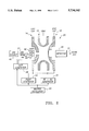
- FIG. 2 is a schematic diagram of a quadrupole ion trap mass spectrometer having two applied voltages resulting in quadrupolar fields according to the invention.
- FIG. 3 is graph plotting a stability region near the origin for the three dimensional ion trap of FIG. 2 showing the iso- ⁇ lines according to the invention.
- the invention provides a technique in which ions are gated into an ion trap. Such gating (discussed in greater detail below) is an optional step that is provided in the preferred embodiment of the invention.
- the gated ions are subjected to parametric resonance within the trap that extracts energy from the ions to thereby facilitate rapid ion trapping.
- methods can be employed as are known in the art and may include, for example modification of the magnitude, frequencies, or phases of the fields created by the potentials applied to the trap electrodes.
- FIG. 2 is a schematic diagram of a quadrupole ion trap mass spectrometer 20 having two applied voltages resulting in quadrupolar fields according to the invention.
- the RF+DC voltage for confinement is produced by an RF+DC generator 22 and applied to the ring electrode 12; and the pump voltage is produced by a pump generator 24 and applied in a unipolar fashion to the endcaps 14, 16.
- the pump generator is preferably an AC signal source, or it may be an RF signal source.
- the signal is preferably synthesized because it is desirable to be able to vary the signal phase and thereby set an optimum signal phase for ion trapping.
- all AC and RF supplies including the input optics gate generator 26, are derived from a master oscillator 20, so that all voltages are phase-coherent.
- phase-coherence can be accomplished by any of several means, such as using supplies with ultra-high frequency stability for each voltage.
- a means may be provided for phasing, i.e. adjusting the timing, of the various voltages with respect to each other.
- the trap 20, detector 30, and ion beam 21 are mounted in an appropriate high-vacuum chamber that may be a single chamber or a multi-chambered vessel having one or more vacuum pumps (not shown) as is known in the art.
- a beam of ions 21, for example from an electrospray or an atmospheric pressure ionization (API) source, 40 is directed toward the trap 20 and, if electrode voltages are favorable, may enter the trap through a small, screened hole in an endcap.
- the beam may be bunched electronically, but this is not essential to the invention. Ions that are allowed to enter the trap are subjected to the two quadrupole fields, i.e. to the superposition of the two fields.
- one feature of the invention provides a gate generator for gating the ions into the ion trap.
- the gate generator is provided to gate the ions into the trap as a bundle, thereby maintaining a proper relationship of ion motion to the phase of the parametric voltage. While in principle, it is possible to allow the ions to enter the trap continuously, the result is that only some of the ions are trapped and other ions are driven even further out of the trap, such that ion collection efficiency is reduced.
- the gate generator is helpful to synchronize the admission of ions into the trap with the pulsing of the pump generator.
- the gate generator is preferably a source of pulsed DC voltage that has a variable pulse width, pulse height, and repetition rate.
- the gate itself can be a simple electrode 28 (FIG. 2) having circular or rectangular hole 42 (FIG. 2) formed therethrough.
- the gate can be an electrode having a hole that is covered with a mesh 44 (FIG. 2); or it can be a set of more than one electrode 28 (FIG. 2) that operates as a gate if one wants to bunch the ions into a smaller Z-axis bundle.
- Such gate would be useful for focusing the position and/or energy of the ions.
- FIG. 3 shows a plot of ion trap parameters with an axis (a) that is proportional to the DC voltage applied to the trap and an axis (q) that is proportional to the AC trapping voltage.
- the normal method of operating an ion trap in mass spectroscopy involves trap operation along the q axis.
- the second field is applied at one of the secular motion frequencies, usually ⁇ z .
- the second voltage is applied to the endcaps as a dipolar field, rather than a quadrupolar field. This causes the ions appropriate to that secular frequency to be excited and to execute motion of ever-increasing amplitude, eventually being driven out of the trap. Ramping of the frequency of the supplementary voltage results in scanning out the ions sequentially by mass.
- supplementary voltages having frequencies other than those of the secular motions can result in energy transfer to or from the ions in the field.
- strong effects can occur if the frequency of the supplementary voltage is twice that of one of the secular frequencies, i.e. 2 ⁇ r or 2 ⁇ z . This is referred to as parametric resonance. See, for example R. E. March, et al., ibid.; and L. D. Landau, E. M. Lifshitz, Mechanics, 3rd Ed., Pergamon, 1976, pp. 80ff.
- Ion ejection from the trap by parametric resonance has been found to be very effective.
- parametric resonance is faster than ion ejection techniques that apply voltages at the secular frequencies, or that raise the a and/or q terms to values that are outside the stability region by increasing the confinement DC or AC voltage magnitude.
- Ejection of ions by parametric resonance occurs only over a certain range of phase of the parametric voltage with respect to the motions of those ions.
- the invention herein exploits to advantage the fact that for other ranges of phases, the ions give up energy, and their motion is damped. Such damping has been neglected in the prior art.
- the invention uses such parametric resonance damping to assist the process of initially trapping the ions.
- the proper phase relationship is accomplished by appropriate electronic timing of ion introduction into the trap with the phase of the parametric voltage.
- Such parametric resonance damping yields an exponential decrease in the amplitude of ion motion, providing much faster trapping than that provided by the use of gas collisions.
- Such damping is also mass-selective because each species of ion only responds to its particular parametric resonance frequency. Thus, the trap is not filled with interfering species, and maximum sensitivity is realized for the species of interest.
- the trapped ions can then be analyzed further by such known techniques as, for example MS/MS or MS n (see, for example R. E. March, J. F. J. Todd, Practical Aspects of Ion Trap Mass Spectrometry, Volume I, Fundamentals Of Ion Trap Mass Spectrometry, CRC Press, 1995).
- More than one species of ion can be trapped simultaneously by applying a parametric field having a complex waveform containing the proper frequency components for the various species of ion, each frequency being applied with the proper phase.
- Parametric pump voltages can also be applied to produce dipolar fields, which also function to damp the ion motion. It is thought that it is also possible to perform parametric pumping and damping in a trap by use of a pump voltage, together with energy trap circuitry at the idler frequency, in analogy with a parametric amplifier. See, for example L. A. Blackwell, K. L. Kotebue, Semiconductor-Diode Parametric Amplifiers, Prentice-Hall, 1961; and W. H. Louisell, Coupled Mode and Parametric Electronics, John Wiley & Sons, 1960.
- the parametric pump voltage may be pumped in a burst, i.e. by turning the voltage on at a definite time with respect to the ion entrance optics pulsing, and then turning the voltage off at an advantageous time.
- the initiation time of the parametric voltage burst is preferably tailored to an optimum position of the ion bunch in the trap, which also depends upon the ion kinetic energy.
Abstract
Description
Claims (16)
Priority Applications (1)
| Application Number | Priority Date | Filing Date | Title |
|---|---|---|---|
| US08/641,260 US5734162A (en) | 1996-04-30 | 1996-04-30 | Method and apparatus for selectively trapping ions into a quadrupole trap |
Applications Claiming Priority (1)
| Application Number | Priority Date | Filing Date | Title |
|---|---|---|---|
| US08/641,260 US5734162A (en) | 1996-04-30 | 1996-04-30 | Method and apparatus for selectively trapping ions into a quadrupole trap |
Publications (1)
| Publication Number | Publication Date |
|---|---|
| US5734162A true US5734162A (en) | 1998-03-31 |
Family
ID=24571633
Family Applications (1)
| Application Number | Title | Priority Date | Filing Date |
|---|---|---|---|
| US08/641,260 Expired - Fee Related US5734162A (en) | 1996-04-30 | 1996-04-30 | Method and apparatus for selectively trapping ions into a quadrupole trap |
Country Status (1)
| Country | Link |
|---|---|
| US (1) | US5734162A (en) |
Cited By (11)
| Publication number | Priority date | Publication date | Assignee | Title |
|---|---|---|---|---|
| US6060706A (en) * | 1997-02-14 | 2000-05-09 | Hitachi, Ltd. | Analytical apparatus using ion trap mass spectrometer |
| US6075243A (en) * | 1996-03-29 | 2000-06-13 | Hitachi, Ltd. | Mass spectrometer |
| US6153880A (en) * | 1999-09-30 | 2000-11-28 | Agilent Technologies, Inc. | Method and apparatus for performance improvement of mass spectrometers using dynamic ion optics |
| US6541766B2 (en) * | 1999-12-02 | 2003-04-01 | Hitachi, Ltd. | Ion trap mass spectrometry and ion trap mass spectrometer |
| US6667487B1 (en) | 2003-01-31 | 2003-12-23 | The United States Of America As Represented By The Administrator Of The National Aeronautics And Space Administration | Radio frequency trap for containment of plasmas in antimatter propulsion systems using rotating wall electric fields |
| US20060219933A1 (en) * | 2005-03-15 | 2006-10-05 | Mingda Wang | Multipole ion mass filter having rotating electric field |
| US20070023629A1 (en) * | 2003-05-30 | 2007-02-01 | Alexander Makarov | All-mass ms/ms method and apparatus |
| US20090146054A1 (en) * | 2007-12-10 | 2009-06-11 | Spacehab, Inc. | End cap voltage control of ion traps |
| US20090294657A1 (en) * | 2008-05-27 | 2009-12-03 | Spacehab, Inc. | Driving a mass spectrometer ion trap or mass filter |
| US20120175518A1 (en) * | 2011-01-10 | 2012-07-12 | Varian Semiconductor Equipment Associates, Inc. | Technique and apparatus for monitoring ion mass, energy, and angle in processing systems |
| US11024497B2 (en) * | 2006-01-02 | 2021-06-01 | Excellims Corp. | Chemically modified ion mobility separation apparatus and method |
Citations (6)
| Publication number | Priority date | Publication date | Assignee | Title |
|---|---|---|---|---|
| US4755670A (en) * | 1986-10-01 | 1988-07-05 | Finnigan Corporation | Fourtier transform quadrupole mass spectrometer and method |
| US4945234A (en) * | 1989-05-19 | 1990-07-31 | Extrel Ftms, Inc. | Method and apparatus for producing an arbitrary excitation spectrum for Fourier transform mass spectrometry |
| US5089703A (en) * | 1991-05-16 | 1992-02-18 | Finnigan Corporation | Method and apparatus for mass analysis in a multipole mass spectrometer |
| US5347127A (en) * | 1991-12-23 | 1994-09-13 | Bruker-Franzen Analytik, Gmbh | Method and device for in-phase excitation of ion ejection from ion trap mass spectrometers |
| US5381007A (en) * | 1991-02-28 | 1995-01-10 | Teledyne Mec A Division Of Teledyne Industries, Inc. | Mass spectrometry method with two applied trapping fields having same spatial form |
| US5436445A (en) * | 1991-02-28 | 1995-07-25 | Teledyne Electronic Technologies | Mass spectrometry method with two applied trapping fields having same spatial form |
-
1996
- 1996-04-30 US US08/641,260 patent/US5734162A/en not_active Expired - Fee Related
Patent Citations (7)
| Publication number | Priority date | Publication date | Assignee | Title |
|---|---|---|---|---|
| US4755670A (en) * | 1986-10-01 | 1988-07-05 | Finnigan Corporation | Fourtier transform quadrupole mass spectrometer and method |
| US4945234A (en) * | 1989-05-19 | 1990-07-31 | Extrel Ftms, Inc. | Method and apparatus for producing an arbitrary excitation spectrum for Fourier transform mass spectrometry |
| US5381007A (en) * | 1991-02-28 | 1995-01-10 | Teledyne Mec A Division Of Teledyne Industries, Inc. | Mass spectrometry method with two applied trapping fields having same spatial form |
| US5436445A (en) * | 1991-02-28 | 1995-07-25 | Teledyne Electronic Technologies | Mass spectrometry method with two applied trapping fields having same spatial form |
| US5561291A (en) * | 1991-02-28 | 1996-10-01 | Teledyne Electronic Technologies | Mass spectrometry method with two applied quadrupole fields |
| US5089703A (en) * | 1991-05-16 | 1992-02-18 | Finnigan Corporation | Method and apparatus for mass analysis in a multipole mass spectrometer |
| US5347127A (en) * | 1991-12-23 | 1994-09-13 | Bruker-Franzen Analytik, Gmbh | Method and device for in-phase excitation of ion ejection from ion trap mass spectrometers |
Non-Patent Citations (4)
| Title |
|---|
| March et al, "Resonance Excitation of Ions Stored in a Quadrupole Ion Trap. Part I. A Simulation Study," Int'l J. of Mass Spectrometry and Ion Processes, 95 (1989) 119-156. |
| March et al, Resonance Excitation of Ions Stored in a Quadrupole Ion Trap. Part I. A Simulation Study, Int l J. of Mass Spectrometry and Ion Processes, 95 (1989) 119 156. * |
| March et al., "Resonance Excitation of Ions Stored in a Quadrupole Ion Trap, Part II. Further Simulation Studies," Inr'l J. of Mass Spectrometry and Ion Porcesses, 99 (1990) 109-124. |
| March et al., Resonance Excitation of Ions Stored in a Quadrupole Ion Trap, Part II. Further Simulation Studies, Inr l J. of Mass Spectrometry and Ion Porcesses, 99 (1990) 109 124. * |
Cited By (19)
| Publication number | Priority date | Publication date | Assignee | Title |
|---|---|---|---|---|
| US6075243A (en) * | 1996-03-29 | 2000-06-13 | Hitachi, Ltd. | Mass spectrometer |
| US6060706A (en) * | 1997-02-14 | 2000-05-09 | Hitachi, Ltd. | Analytical apparatus using ion trap mass spectrometer |
| US6153880A (en) * | 1999-09-30 | 2000-11-28 | Agilent Technologies, Inc. | Method and apparatus for performance improvement of mass spectrometers using dynamic ion optics |
| US6541766B2 (en) * | 1999-12-02 | 2003-04-01 | Hitachi, Ltd. | Ion trap mass spectrometry and ion trap mass spectrometer |
| US6667487B1 (en) | 2003-01-31 | 2003-12-23 | The United States Of America As Represented By The Administrator Of The National Aeronautics And Space Administration | Radio frequency trap for containment of plasmas in antimatter propulsion systems using rotating wall electric fields |
| US7399962B2 (en) * | 2003-05-30 | 2008-07-15 | Thermo Finnigan Llc | All-mass MS/MS method and apparatus |
| US7728290B2 (en) * | 2003-05-30 | 2010-06-01 | Thermo Finnigan Llc | Orbital ion trap including an MS/MS method and apparatus |
| US20070023629A1 (en) * | 2003-05-30 | 2007-02-01 | Alexander Makarov | All-mass ms/ms method and apparatus |
| US20080258053A1 (en) * | 2003-05-30 | 2008-10-23 | Alexander Makarov | All-mass ms/ms method and apparatus |
| US20060219933A1 (en) * | 2005-03-15 | 2006-10-05 | Mingda Wang | Multipole ion mass filter having rotating electric field |
| US7183545B2 (en) | 2005-03-15 | 2007-02-27 | Agilent Technologies, Inc. | Multipole ion mass filter having rotating electric field |
| US11024497B2 (en) * | 2006-01-02 | 2021-06-01 | Excellims Corp. | Chemically modified ion mobility separation apparatus and method |
| US20090146054A1 (en) * | 2007-12-10 | 2009-06-11 | Spacehab, Inc. | End cap voltage control of ion traps |
| US8334506B2 (en) | 2007-12-10 | 2012-12-18 | 1St Detect Corporation | End cap voltage control of ion traps |
| US8704168B2 (en) | 2007-12-10 | 2014-04-22 | 1St Detect Corporation | End cap voltage control of ion traps |
| US20090294657A1 (en) * | 2008-05-27 | 2009-12-03 | Spacehab, Inc. | Driving a mass spectrometer ion trap or mass filter |
| US7973277B2 (en) | 2008-05-27 | 2011-07-05 | 1St Detect Corporation | Driving a mass spectrometer ion trap or mass filter |
| US20120175518A1 (en) * | 2011-01-10 | 2012-07-12 | Varian Semiconductor Equipment Associates, Inc. | Technique and apparatus for monitoring ion mass, energy, and angle in processing systems |
| US8698107B2 (en) * | 2011-01-10 | 2014-04-15 | Varian Semiconductor Equipment Associates, Inc. | Technique and apparatus for monitoring ion mass, energy, and angle in processing systems |
Similar Documents
| Publication | Publication Date | Title |
|---|---|---|
| US5714755A (en) | Mass scanning method using an ion trap mass spectrometer | |
| US4755670A (en) | Fourtier transform quadrupole mass spectrometer and method | |
| US5561291A (en) | Mass spectrometry method with two applied quadrupole fields | |
| CA2239399C (en) | Axial ejection in a multipole mass spectrometer | |
| US7034293B2 (en) | Linear ion trap apparatus and method utilizing an asymmetrical trapping field | |
| JP3064422B2 (en) | Mass spectrometry using two capture fields with the same spatial shape | |
| JP3818671B2 (en) | Axial injection method of multipole mass spectrometer | |
| US7842918B2 (en) | Chemical structure-insensitive method and apparatus for dissociating ions | |
| EP1508155B1 (en) | Axial ejection resolution in multipole mass spectrometers | |
| US6831275B2 (en) | Nonlinear resonance ejection from linear ion traps | |
| US5734162A (en) | Method and apparatus for selectively trapping ions into a quadrupole trap | |
| JPS6237861A (en) | Mass spectrograph utilizing ion trap | |
| CA2178244C (en) | Method of detecting selected ion species in a quadrupole ion trap | |
| US6900433B2 (en) | Method and apparatus for ejecting ions from a quadrupole ion trap | |
| AU722099B2 (en) | Method for trapping ions into ion traps and ion trap mass spectrometer system thereof | |
| Michaud et al. | Ion excitation in a linear quadrupole ion trap with an added octopole field | |
| US20030189168A1 (en) | Fragmentation of ions by resonant excitation in a low pressure ion trap | |
| Collings et al. | Observation of higher order quadrupole excitation frequencies in a linear ion trap | |
| Lammert et al. | Determination of ion frequencies in a quadrupole ion trap by using a fast direct current pulse as pump and a laser probe | |
| Sheretov et al. | Mass selective instability mode without a light buffer gas | |
| Pitsenberger et al. | Filtered white noise and repetitive chirp broadband quadrupolar excitation Fourier transform ion cyclotron resonance mass spectrometry at 1 tesla |
Legal Events
| Date | Code | Title | Description |
|---|---|---|---|
| AS | Assignment |
Owner name: HEWLETT-PACKARD COMPANY, CALIFORNIA Free format text: ASSIGNMENT OF ASSIGNORS INTEREST;ASSIGNOR:DOWELL, JERRY T.;REEL/FRAME:008056/0522 Effective date: 19960422 |
|
| AS | Assignment |
Owner name: HEWLETT-PACKARD COMPANY, A DELAWARE CORPORATION, C Free format text: MERGER;ASSIGNOR:HEWLETT-PACKARD COMPANY, A CALIFORNIA CORPORATION;REEL/FRAME:010841/0649 Effective date: 19980520 |
|
| AS | Assignment |
Owner name: AGILENT TECHNOLOGIES INC, CALIFORNIA Free format text: ASSIGNMENT OF ASSIGNORS INTEREST;ASSIGNOR:HEWLETT-PACKARD COMPANY;REEL/FRAME:010977/0540 Effective date: 19991101 |
|
| FEPP | Fee payment procedure |
Free format text: PAYOR NUMBER ASSIGNED (ORIGINAL EVENT CODE: ASPN); ENTITY STATUS OF PATENT OWNER: LARGE ENTITY |
|
| FPAY | Fee payment |
Year of fee payment: 4 |
|
| REMI | Maintenance fee reminder mailed | ||
| LAPS | Lapse for failure to pay maintenance fees | ||
| LAPS | Lapse for failure to pay maintenance fees |
Free format text: PATENT EXPIRED FOR FAILURE TO PAY MAINTENANCE FEES (ORIGINAL EVENT CODE: EXP.); ENTITY STATUS OF PATENT OWNER: LARGE ENTITY |
|
| STCH | Information on status: patent discontinuation |
Free format text: PATENT EXPIRED DUE TO NONPAYMENT OF MAINTENANCE FEES UNDER 37 CFR 1.362 |
|
| FP | Lapsed due to failure to pay maintenance fee |
Effective date: 20060331 |