US5724362A - Apparatus and method employing a window reset for excessive bit error rate alarm detection and clearing - Google Patents
Apparatus and method employing a window reset for excessive bit error rate alarm detection and clearing Download PDFInfo
- Publication number
- US5724362A US5724362A US08/536,056 US53605695A US5724362A US 5724362 A US5724362 A US 5724362A US 53605695 A US53605695 A US 53605695A US 5724362 A US5724362 A US 5724362A
- Authority
- US
- United States
- Prior art keywords
- blocks
- count
- block
- window
- state
- Prior art date
- Legal status (The legal status is an assumption and is not a legal conclusion. Google has not performed a legal analysis and makes no representation as to the accuracy of the status listed.)
- Expired - Lifetime
Links
- 238000000034 method Methods 0.000 title claims abstract description 46
- 238000001514 detection method Methods 0.000 title claims description 24
- 238000012544 monitoring process Methods 0.000 claims description 6
- 238000004364 calculation method Methods 0.000 abstract description 32
- RGNPBRKPHBKNKX-UHFFFAOYSA-N hexaflumuron Chemical compound C1=C(Cl)C(OC(F)(F)C(F)F)=C(Cl)C=C1NC(=O)NC(=O)C1=C(F)C=CC=C1F RGNPBRKPHBKNKX-UHFFFAOYSA-N 0.000 description 10
- 230000006870 function Effects 0.000 description 6
- 102100040338 Ubiquitin-associated and SH3 domain-containing protein B Human genes 0.000 description 5
- 101710143616 Ubiquitin-associated and SH3 domain-containing protein B Proteins 0.000 description 5
- 230000001186 cumulative effect Effects 0.000 description 3
- 239000000835 fiber Substances 0.000 description 3
- 230000001360 synchronised effect Effects 0.000 description 3
- RYGMFSIKBFXOCR-UHFFFAOYSA-N Copper Chemical compound [Cu] RYGMFSIKBFXOCR-UHFFFAOYSA-N 0.000 description 2
- 230000005540 biological transmission Effects 0.000 description 2
- 229910052802 copper Inorganic materials 0.000 description 2
- 239000010949 copper Substances 0.000 description 2
- 238000010586 diagram Methods 0.000 description 2
- 230000036039 immunity Effects 0.000 description 1
- 230000000977 initiatory effect Effects 0.000 description 1
- 238000012986 modification Methods 0.000 description 1
- 230000004048 modification Effects 0.000 description 1
- 230000003287 optical effect Effects 0.000 description 1
Images


Classifications
-
- H—ELECTRICITY
- H04—ELECTRIC COMMUNICATION TECHNIQUE
- H04L—TRANSMISSION OF DIGITAL INFORMATION, e.g. TELEGRAPHIC COMMUNICATION
- H04L1/00—Arrangements for detecting or preventing errors in the information received
- H04L1/24—Testing correct operation
-
- H—ELECTRICITY
- H04—ELECTRIC COMMUNICATION TECHNIQUE
- H04L—TRANSMISSION OF DIGITAL INFORMATION, e.g. TELEGRAPHIC COMMUNICATION
- H04L43/00—Arrangements for monitoring or testing data switching networks
- H04L43/08—Monitoring or testing based on specific metrics, e.g. QoS, energy consumption or environmental parameters
- H04L43/0823—Errors, e.g. transmission errors
- H04L43/0847—Transmission error
-
- H—ELECTRICITY
- H04—ELECTRIC COMMUNICATION TECHNIQUE
- H04L—TRANSMISSION OF DIGITAL INFORMATION, e.g. TELEGRAPHIC COMMUNICATION
- H04L43/00—Arrangements for monitoring or testing data switching networks
- H04L43/16—Threshold monitoring
Definitions
- the present invention relates generally to the field of telecommunications. More particularly, the present invention relates to apparatus and methods for in-service performance monitoring of high speed synchronous digital telecommunications signals.
- Fiber optic cable has proved to be a valuable tool of such evolution, replacing copper cable in nearly ever application from large trunks to subscriber distribution plants. Fiber optic cable is capable of carrying much more information than copper with better noise immunity.
- SONET Synchronous Optical Network
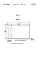
- FIG. 1 which shows a SONET STS-1 frame
- SONET signals are sent in a frame format which includes section overhead and line overhead which together are taken as transport overhead (TOH) arranged as columns of bytes, and a payload which are also arranged as columns of bytes.
- TOH transport overhead
- the bytes of the payload include "path layer overhead" (POH) bytes.
- POH path layer overhead
- FIG. 2 which details the TOH and POH bytes, among the TOH bytes are bytes B1 and B2 which are eight-bit interleave parity (BIP-8) codes.
- the path overhead includes byte B3 which is a BIP-8 code byte.
- SONET signals and SDH (Synchronous Digital Hierarchy) Signals which are closely related to SONET signals use the BIP-8 bytes in the transport and path overhead to monitor in-service performance.
- the number of received BIP-8 code violations can be converted to the bit error rate (BER) of an STS-N type signal.
- BER bit error rate
- TR-NWT-000253 a user selected BER threshold ranging from 1 ⁇ 10 -3 to 1 ⁇ 10 -9 is then used to indicate signal fail (SF) and signal degrade (SD) conditions for the initiation of an automatic protection switching (ASP). (See Section 5.3 of Bellcore TR-NWT-000253).
- the maximum detection time requirement and an average detection time objective which depend upon the chosen BER level.
- the maximum alarm detection time for a BER of 1 ⁇ 10 -3 is 10 ms
- the maximum detection time for a BER of 1 ⁇ 10 -5 is one second.
- the average detection time objective for the BER of 1 ⁇ 10 -3 is 8 ms
- the algorithm used to detect alarm conditions should also be tolerant to burst errors of up to 3 ms.
- a sliding window algorithm (SWA) is suggested in Bellcore TR-NWT-000253.
- M t consecutive blocks of data are examined, where M t equals the maximum number of blocks observed before reinitialization (for alarm). If there are m t or more blocks (where m t is a desired flag count threshold number) each having m or more parity violations (where m is a parity violation count threshold) in the M t blocks, an alarm will be issued. If not, the window of the M t consecutive blocks is advanced (slid) by a single block, and the calculations are repeated for that set of M t consecutive blocks. Again, if there are m t or more blocks each having m or more parity violations, an alarm will be issued. If not, the window is again slid, and the calculations repeated.
- the BIP-8 code violation In implementing the sliding window algorithm for a window size of N frames, the BIP-8 code violation must be checked for the current frame and the previous N-1 frames, and the previous N-1 BIP-8 code violations must be stored.
- the requirement of checking the BER every frame, and storing the previous N-1 BIP-8 code violations places a large strain on hardware and/or software implementing the SWA. In fact, in order to meet the BER threshold of ⁇ 10 -3 with the detection time objective of 8 ms, only hardware or VLSI implementation is feasible.
- the false alarm rate for declaring a signal degrade or failure is unacceptably high.
- EBER excessive bit error rate
- the method of generating and clearing an EBER alarm broadly comprises utilizing a reset window algorithm rather than a sliding window algorithm.
- BIP-8 bytes e.g., B2 bytes
- incoming data blocks each block being B frames long
- CVSET code violation count threshold
- a counter is initialized in a "crossing calculation state"
- a window comprising a plurality (W) of blocks (including the first block and the W-1 succeeding blocks) are monitored.
- the counter is used to count the number of incoming blocks in the window having a code violation count (CV) which meets or exceeds the code violation count threshold (CVSET). If in the crossing calculation state, the count (SC) meets or exceeds its own threshold (X), a BER alarm (i.e., excessive bit error rate EBER condition) or "alarm state” is declared. If not, the system returns to the "idle state" where incoming data is again monitored on a block by block basis until a block has a code violation count CV meeting or exceeding the threshold CVSET.
- CV code violation count
- CVSET code violation count threshold
- Every received block is monitored for its code violation count.
- the first received block with a CV count of CVCLR (code violation clear) or less initializes an alarm clearing check ("clearing calculation state") which sets a clearing-counter CC.
- the clearing counter CC is used to count the number of incoming blocks in the window having a code violation count (CV) of CVCLR or less. If the CC count meets a third threshold value Y within the time window, the alarm is cleared and the system returns to the idle state. Otherwise, the system reverts to the alarm state.
- the number of frames B in a block, the number of blocks W in a window, and the threshold values X, Y, CVSET, and CVCLR are chosen to meet the maximum detection time, and the objective of average detection time for different bit error rates.
- the burst-proof requirement of 3 ms is also met.
- a hardware or software apparatus having four or five counters, and six registers is utilized in practicing the method of the invention.
- the counters include a code violation counter CV for counting BIP-8 errors, a set counter SC for counting the number of blocks having CV ⁇ CVSET, a clear counter CC for counting the number of blocks having CV ⁇ CVCLR, a block counter BC for counting the window length W, and a frame counter FC for counting the number of frames B in a block.
- the set counter SC can be reused as the clear counter CC.
- the registers include registers for storing values for thresholds CVSET, CVCLR, X, and Y, and registers for storing values for the number of blocks W in a window, and the number of frames B in a block.
- FIG. 1 is a prior art representation of the layout of a SONET STS-1 frame.
- FIG. 2 is a prior art representation of specific bytes in the section, line, and path layer overhead portions of the STS-1 frame of FIG. 1.
- FIG. 3 is a flow chart of the reset window method of the invention for generating and clearing bit error rate alarms.
- FIG. 4 is a block diagram of a VLSI apparatus which generates and clears bit error rate alarms in accord with the reset window method of the invention.
- the "reset window” method of the invention for generating and clearing bit error rate alarms is seen in flow chart form.
- the method defines four states: an idle state 10, a crossing calculation state 20, an alarm state 30, and a clearing calculation state 40.
- an idle state 10 the number of code violations contained in blocks of data (each block being B frames long) are monitored on a block by block basis in order to determine whether to remain in the idle state or to move from the idle state into the crossing calculation state 20.
- the crossing calculation state 20 a window containing a plurality of blocks is monitored in order to determine whether to move back to the idle state or to declare an alarm state 30 and set the EBER alarm.
- the number of code violations are again monitored on a block by block basis in order to determine whether to remain in the alarm state or to move from the alarm state into the clearing calculation state 40.
- the clearing calculation state 40 another window of blocks is monitored in order to determine whether to return to the alarm state or to move to the idle state and clear the EBER alarm.
- the method starts in the idle state 10, where no EBER alarm has been declared, or where such an alarm has been cleared.
- the BIP-8 byte(s) under surveillance e.g., the B2 byte of the frame
- CVSET Code Violation SET
- a window comprising a plurality (W) of successive blocks (including the block which caused movement from the idle state 10 into the crossing calculation state 20) is monitored.
- the block counter BC is used to track the number of blocks in the window
- the set counter SC is used to track the number of blocks containing a cumulative number of code violations greater than or equal to CVSET.
- the alarm state is declared at 30 (upon reaching the threshold value), and the EBER alarm is set. Otherwise, as indicated at 27, the method returns to the idle state 10 where each block is analyzed on a block by block basis to determine whether to re-enter the crossing calculation state 20.
- the code violations are again analyzed on a block by block basis.
- CVCLR Code Violation CLeaR
- the method remains in the alarm state, and the next block is analyzed.
- the number of code violations in a block is less than or equal to the value CVCLR as indicated at 34, two counters (the "clear counter” CC and the block counter BC) are (re) initialized to a value "1" at 36, and the clearing calculation state is declared at 40.
- a second window of the predetermined number W of blocks is analyzed to determine how many of the blocks contain code violations in excess of the threshold CVCLR.
- the threshold value CVCLR as indicated at 41, only the block counter BC is incremented at 42. If the code violations for that block is equal to or less than the threshold value CVCLR as indicated at 43, both the clear counter CC and the block counter BC are incremented at 44.
- the EBER alarm is cleared (upon reaching the threshold), and the method returns to the idle state.
- the number of frames B in a block, the number of blocks W in a window, and the threshold values X, Y, CVSET, and CVCLR may be set to meet the maximum detection time, and the objective of average detection time for different bit error rates. Accordingly, preferred threshold values, and values for parameters B and W are as set forth in Table 1:
- the objective of average detection time of 8 ms for that BER threshold will likewise be met.
- FIG. 4 a block diagram of an apparatus 100 which implements the method of the invention is seen.
- the BIP-8 codes contained in the B1, B2, and B3 bytes of the STSn signal frame are parity bytes of different portions of the previous frame. It will also be appreciated that in obtaining a bit error (code violation) count, it is necessary to calculate from the incoming free, the BIP code value for the frame that was received, and then compare that value to the BIP-8 value received in the next frame. Therefore, as shown in FIG.
- the BIP-8 code for the desired byte (e.g., B2) is calculated by block 102, and stored in buffer 104 so that it can be compared by a comparator 106 to the BIP-8 code received in the next frame.
- the comparison carried out by the comparator can yield anywhere between zero and eight code violation errors (CV).
- the BIP-8 error count (CV) is accumulated in an accumulator or counter 108 for each block of data being received.
- the accumulator 108 which receives the BIP-8 error count determined by comparator 106 is reset each frame after it provides it results to the EBER state machine 110.
- the BIP-8 error count is accumulated in accumulator 108 until the block of data is finished. Only after the block of data is finished, and the results are provided to the state machine 110 is the accumulator reset.
- the accumulated BIP-8 error count CV is only one of several values which are provided to the EBER state machine 110 (although it is the only regularly changed variable).
- the other values include register values for the thresholds CVSET, CVCLR, X, and Y, and register values which indicate the number of blocks W in a window, and the number of frees B in a block.
- a frame signal and a clock signal are provided to the state machine 110.
- a block counter (BC) 112 Associated with the EBER state machine 110 are four counters: a block counter (BC) 112, a set counter (SC) 114, a clear counter (CC) 116, and a frame counter (FC) 118.
- BC block counter
- SC set counter
- CC clear counter
- FC frame counter
- the EBER state machine 110 is a state machine which is preferably implemented in VLSI hardware, although it may be implemented in either software or other hardware. Regardless of how implemented, the functioning of the state machine is governed according to the flow chart of FIG. 3. Likewise, it should be appreciated that the counters 112, 114, 116, and 118, as well as the BIP-8 calculation block 102, the buffer 104, the comparator 106, and the accumulator 108 may also be implemented in hardware or software. Further, the inputs CVSET, CVCLR, X, Y, W, and B to the state machine 110 may implemented as values stored in hardware registers or in software. If desired, the set counter 114 and clear counter 116 can be implemented as a single counter, as the set and clearing functions are never utilized at the same time; i.e., counters 114 and 116 will never be active together.
- the user is preferably permitted to set the bit error rate threshold at which an alarm will be generated.
- the user preferably defines values for the parameters B, W, X, Y, CVSET, and CVCLR, with preferred values set forth above in Table 1.
- the parameter values set as bytes of the STSn signal are received, they are used to calculate a BIP-8 value for that frame.
- the calculated BIP-8 value is then compared to the received corresponding BIP-8 value of the next frame in order to determine a BIP error count.
- the frame counter 118 is updated every frame, and is used to track the start (or end) of each block (i.e., the count of the frame counter 118 is compared to the EBER state machine input value B).
- the EBER state machine 110 outputs a reset Signal to the BIP error counter 108 based on the count of the frame counter 118.
- the BIP error counter 108 accumulates the BIP error count for the block.
- the state machine 110 determines that the count of counter 108 exceeds the threshold value CVSET, the block counter 112, and set counter 114 are preferably initialized to a value "1".
- the apparatus including the state machine, then continues to function as previously described, but in the crossing calculation state.
- the block counter 112 is incremented after each block and compared to the value W in order to determine whether the window has been completed. Furthermore, the set counter 114 which is incremented each block where the BIP-8 error count CV exceeds the threshold CVSET, is compared to the alarm set threshold value X. Depending upon the value of the set counter (as compared to X), the state machine may either move into the alarm state and output an alarm BN*EBER, or, upon completion of the window W, may move back to the idle state.
- the EBER state machine functions in a manner similar to the idle state, except that the accumulated BIP error count CV is now compared to the threshold value CVCLR instead of CVSET, and the EBER alarm is being output.
- the state machine 110 determines that the count of counter 108 is less than or equals the threshold value CVCLR, the block counter 112, and clear counter 116 are preferably initialized to a value "1".
- the apparatus including the state machine, then continues to function as previously described, but in the clearing calculation state.
- the block counter 112 is incremented after each block and compared to the value W in order to determine whether the window has been completed. Furthermore, the clear counter 114 which is incremented each block where the BIP error count CV equals or is less than the threshold CVCLR, is compared to the alarm clear threshold value Y. Depending upon the value of the clear counter 114 (as compared to Y), the state machine may move to the idle state and clear the EBER alarm, or, upon the completion of the window, the state machine may move back into the alarm state.
- a determination as to whether to move (or return) to the idle state or to the alarm state is made based on the information from a single window. After a decision is made, and the state is changed to the idle state or the alarm state, a determination as to whether to enter the crossing calculation state or clearing calculation state from the idle state or alarm state is made on a block by block basis. If the crossing or clearing calculation state is re-entered, a completely new time window is established which does not overlap with the previous time window.
- the apparatus and method of the invention effectively employ a "window reset" as opposed to a sliding window algorithm with the associated advantages as mentioned before.
- the apparatus and method of the invention can be utilized to set an alarms for any or all of the B1, B2, and B3 bytes of the SONET signal; and the SONET signal may be an STS-1, STS-3, or any other SONET signal of interest.
- the SONET signal may be an STS-1, STS-3, or any other SONET signal of interest.
- additional apparatus which is essentially identical to the apparatus shown in FIG. 4 could be utilized.
- the method of the invention was described as comparing the set counter to see whether it equalled or exceeded a threshold value X, and comparing the clear counter to see whether it was less than a threshold value Y, it will be appreciated that inverse function or other functions could be utilized.
- the "set counter” could be incremented only when the BIP error count CV was less than CVSET, and the alarm set when the "set counter" was less than a predetermined value X'.
- the threshold value could be increased such that the bit error count must be greater than CVSET, rather than greater than or equal to CVSET in order to increment the set counter.
Abstract
Description
              TABLE 1
______________________________________
     W       B       X     CVSET  Y      CVCLR
BER  (blocks)
             (frames)
                     (blocks)
                           (CV/blk)
                                  (blocks)
                                         (CV/blk)
______________________________________
10.sup.-3
      67        1    39    3       28    0
10.sup.-4
     160        2    44    2      122    0
10.sup.-5
     160       20    48    2      122    0
10.sup.-6
     160       200   48    2      122    0
10.sup.-7
     160      2000   48    2      122    0
10.sup.-8
     160      20000  48    2      122    0
10.sup.-9
     160     200000  48    2      122    0
______________________________________
Claims (27)
Priority Applications (8)
| Application Number | Priority Date | Filing Date | Title |
|---|---|---|---|
| US08/536,056 US5724362A (en) | 1995-09-29 | 1995-09-29 | Apparatus and method employing a window reset for excessive bit error rate alarm detection and clearing |
| PCT/US1996/015587 WO1997012323A1 (en) | 1995-09-29 | 1996-09-27 | Apparatus and method employing a window reset for excessive bit error rate alarm detection and clearing |
| CN96197257A CN1093958C (en) | 1995-09-29 | 1996-09-27 | Apparatus and method employing window reset for excessive bit error rate alarm detection and clearing |
| DE69632077T DE69632077T2 (en) | 1995-09-29 | 1996-09-27 | DEVICE AND METHOD USING A WINDOW RESET FOR ALARM DETECTION AND REMOVAL FOR EXCESSIVE ERROR BITRATES |
| IL12384296A IL123842A (en) | 1995-09-29 | 1996-09-27 | Apparatus and method employing a window reset for excessive bit error rate alarm detection and clearing |
| EP96936047A EP0880742B1 (en) | 1995-09-29 | 1996-09-27 | Apparatus and method employing a window reset for excessive bit error rate alarm detection and clearing |
| AU73786/96A AU7378696A (en) | 1995-09-29 | 1996-09-27 | Apparatus and method employing a window reset for excessive bit error rate alarm detection and clearing |
| CA002231098A CA2231098C (en) | 1995-09-29 | 1996-09-27 | Apparatus and method employing a window reset for excessive bit error rate alarm detection and clearing |
Applications Claiming Priority (1)
| Application Number | Priority Date | Filing Date | Title |
|---|---|---|---|
| US08/536,056 US5724362A (en) | 1995-09-29 | 1995-09-29 | Apparatus and method employing a window reset for excessive bit error rate alarm detection and clearing |
Publications (1)
| Publication Number | Publication Date |
|---|---|
| US5724362A true US5724362A (en) | 1998-03-03 |
Family
ID=24136944
Family Applications (1)
| Application Number | Title | Priority Date | Filing Date |
|---|---|---|---|
| US08/536,056 Expired - Lifetime US5724362A (en) | 1995-09-29 | 1995-09-29 | Apparatus and method employing a window reset for excessive bit error rate alarm detection and clearing |
Country Status (8)
| Country | Link |
|---|---|
| US (1) | US5724362A (en) |
| EP (1) | EP0880742B1 (en) |
| CN (1) | CN1093958C (en) |
| AU (1) | AU7378696A (en) |
| CA (1) | CA2231098C (en) |
| DE (1) | DE69632077T2 (en) |
| IL (1) | IL123842A (en) |
| WO (1) | WO1997012323A1 (en) |
Cited By (14)
| Publication number | Priority date | Publication date | Assignee | Title |
|---|---|---|---|---|
| WO2001020452A1 (en) * | 1999-09-17 | 2001-03-22 | Digital Lightwave, Inc. | Protocol and bit rate independent test system |
| US6310911B1 (en) * | 1997-02-11 | 2001-10-30 | Alcatel Canada Inc. | Method of detecting signal degradation fault conditions within SONET and SDH signals |
| US20020049838A1 (en) * | 2000-06-21 | 2002-04-25 | Sylor Mark W. | Liveexception system |
| US20020126695A1 (en) * | 1999-10-26 | 2002-09-12 | Hiroshi Yoshida | Concatenation signal communication system |
| WO2002079988A1 (en) * | 2001-03-29 | 2002-10-10 | Transwitch Corporation | Methods and apparatus for burst toleran excessive bit error rate alarm detection and clearing |
| US6529519B1 (en) * | 1998-12-22 | 2003-03-04 | Koninklijke Philips Electronics N.V. | Prioritized-buffer management for fixed sized packets in multimedia application |
| US6591383B1 (en) * | 1999-11-19 | 2003-07-08 | Eci Telecom Ltd. | Bit error rate detection |
| US20040103350A1 (en) * | 2002-11-27 | 2004-05-27 | Adc Dsl Systems, Inc. | Analyzing an attribute of a communication link |
| US20040243888A1 (en) * | 2003-05-30 | 2004-12-02 | Lucent Technologies Inc. | Protection switching in WDM rings using a shared ring switch |
| US20050197792A1 (en) * | 2004-03-03 | 2005-09-08 | Michael Haeuptle | Sliding window for alert generation |
| US6993700B1 (en) * | 2000-12-22 | 2006-01-31 | Applied Micro Circuits Corporation | System and method for generating forward error correction based alarms |
| US9929970B1 (en) * | 2015-12-03 | 2018-03-27 | Innovium, Inc. | Efficient resource tracking |
| US10218589B1 (en) | 2015-12-17 | 2019-02-26 | Innovium, Inc. | Efficient resource status reporting apparatuses |
| US10432429B1 (en) | 2016-02-16 | 2019-10-01 | Innovium, Inc. | Efficient traffic management |
Families Citing this family (4)
| Publication number | Priority date | Publication date | Assignee | Title |
|---|---|---|---|---|
| US6298038B1 (en) * | 1997-04-24 | 2001-10-02 | Nortel Networks Limited | Transparent transport |
| SE513188C2 (en) | 1998-03-25 | 2000-07-24 | Ericsson Telefon Ab L M | Quota algorithm for monitoring disturbance processes |
| CN100397829C (en) * | 2002-12-27 | 2008-06-25 | 华为技术有限公司 | Warning method for frequent discrete event fault |
| DE102007029660B4 (en) * | 2007-06-27 | 2011-06-01 | Vega Grieshaber Kg | Adaptive error counter for a wireless field device |
Citations (4)
| Publication number | Priority date | Publication date | Assignee | Title |
|---|---|---|---|---|
| US3916379A (en) * | 1974-04-08 | 1975-10-28 | Honeywell Inf Systems | Error-rate monitoring unit in a communication system |
| US5138616A (en) * | 1990-03-19 | 1992-08-11 | The United States Of America As Represented By The Secretary Of The Army | Continuous on-line link error rate detector utilizing the frame bit error rate |
| US5467341A (en) * | 1994-04-14 | 1995-11-14 | Toshiba America Information Systems, Inc. | Apparatus and method for alerting computer users in a wireless LAN of a service area transition |
| US5570373A (en) * | 1995-03-20 | 1996-10-29 | Lucent Technologies Inc. | Method and apparatus for testing a radio in a base station without using a radio test unit |
Family Cites Families (4)
| Publication number | Priority date | Publication date | Assignee | Title |
|---|---|---|---|---|
| US3991278A (en) * | 1975-06-13 | 1976-11-09 | Bell Telephone Laboratories, Incorporated | Line protection switching system |
| ZA804385B (en) * | 1979-08-10 | 1981-07-29 | Plessey Co Ltd | Alarm monitoring arrangements for digital telecommunications switching networks |
| CA1144617A (en) * | 1980-11-25 | 1983-04-12 | Northern Telecom Limited | Error performance monitoring for digital transmission systems |
| US5377195A (en) * | 1992-04-02 | 1994-12-27 | Telefonaktiebolaget L M Ericsson | Leaky bucket for supervision in industrial processes |
-
1995
- 1995-09-29 US US08/536,056 patent/US5724362A/en not_active Expired - Lifetime
-
1996
- 1996-09-27 DE DE69632077T patent/DE69632077T2/en not_active Expired - Lifetime
- 1996-09-27 CN CN96197257A patent/CN1093958C/en not_active Expired - Fee Related
- 1996-09-27 EP EP96936047A patent/EP0880742B1/en not_active Expired - Lifetime
- 1996-09-27 IL IL12384296A patent/IL123842A/en not_active IP Right Cessation
- 1996-09-27 WO PCT/US1996/015587 patent/WO1997012323A1/en active IP Right Grant
- 1996-09-27 CA CA002231098A patent/CA2231098C/en not_active Expired - Fee Related
- 1996-09-27 AU AU73786/96A patent/AU7378696A/en not_active Abandoned
Patent Citations (4)
| Publication number | Priority date | Publication date | Assignee | Title |
|---|---|---|---|---|
| US3916379A (en) * | 1974-04-08 | 1975-10-28 | Honeywell Inf Systems | Error-rate monitoring unit in a communication system |
| US5138616A (en) * | 1990-03-19 | 1992-08-11 | The United States Of America As Represented By The Secretary Of The Army | Continuous on-line link error rate detector utilizing the frame bit error rate |
| US5467341A (en) * | 1994-04-14 | 1995-11-14 | Toshiba America Information Systems, Inc. | Apparatus and method for alerting computer users in a wireless LAN of a service area transition |
| US5570373A (en) * | 1995-03-20 | 1996-10-29 | Lucent Technologies Inc. | Method and apparatus for testing a radio in a base station without using a radio test unit |
Cited By (29)
| Publication number | Priority date | Publication date | Assignee | Title |
|---|---|---|---|---|
| US6310911B1 (en) * | 1997-02-11 | 2001-10-30 | Alcatel Canada Inc. | Method of detecting signal degradation fault conditions within SONET and SDH signals |
| US6529519B1 (en) * | 1998-12-22 | 2003-03-04 | Koninklijke Philips Electronics N.V. | Prioritized-buffer management for fixed sized packets in multimedia application |
| WO2001020452A1 (en) * | 1999-09-17 | 2001-03-22 | Digital Lightwave, Inc. | Protocol and bit rate independent test system |
| US6430715B1 (en) * | 1999-09-17 | 2002-08-06 | Digital Lightwave, Inc. | Protocol and bit rate independent test system |
| US20020126695A1 (en) * | 1999-10-26 | 2002-09-12 | Hiroshi Yoshida | Concatenation signal communication system |
| US6591383B1 (en) * | 1999-11-19 | 2003-07-08 | Eci Telecom Ltd. | Bit error rate detection |
| US20090234944A1 (en) * | 2000-06-21 | 2009-09-17 | Sylor Mark W | Liveexception system |
| AU2001270017B2 (en) * | 2000-06-21 | 2008-03-13 | Computer Associates Think, Inc. | Liveexception system |
| EP1352332A1 (en) * | 2000-06-21 | 2003-10-15 | Concord Communications, Inc. | Liveexception system |
| US7877472B2 (en) | 2000-06-21 | 2011-01-25 | Computer Associates Think, Inc. | System and method for displaying historical performance of an element on a network |
| US20020049838A1 (en) * | 2000-06-21 | 2002-04-25 | Sylor Mark W. | Liveexception system |
| EP1352332A4 (en) * | 2000-06-21 | 2004-12-08 | Concord Communications Inc | Liveexception system |
| US7490145B2 (en) * | 2000-06-21 | 2009-02-10 | Computer Associates Think, Inc. | LiveException system |
| US6993700B1 (en) * | 2000-12-22 | 2006-01-31 | Applied Micro Circuits Corporation | System and method for generating forward error correction based alarms |
| EP1381946A1 (en) * | 2001-03-29 | 2004-01-21 | Transwitch Corporation | Methods and apparatus for burst toleran excessive bit error rate alarm detection and clearing |
| US6775237B2 (en) | 2001-03-29 | 2004-08-10 | Transwitch Corp. | Methods and apparatus for burst tolerant excessive bit error rate alarm detection and clearing |
| EP1381946A4 (en) * | 2001-03-29 | 2005-01-19 | Transwitch Corp | Methods and apparatus for burst toleran excessive bit error rate alarm detection and clearing |
| WO2002079988A1 (en) * | 2001-03-29 | 2002-10-10 | Transwitch Corporation | Methods and apparatus for burst toleran excessive bit error rate alarm detection and clearing |
| US7051249B2 (en) * | 2002-11-27 | 2006-05-23 | Adc Dsl Systems, Inc. | Analyzing a bit error rate of a communication link |
| US20040103350A1 (en) * | 2002-11-27 | 2004-05-27 | Adc Dsl Systems, Inc. | Analyzing an attribute of a communication link |
| US20040243888A1 (en) * | 2003-05-30 | 2004-12-02 | Lucent Technologies Inc. | Protection switching in WDM rings using a shared ring switch |
| US8417112B2 (en) * | 2003-05-30 | 2013-04-09 | Alcatel Lucent | Protection switching in WDM rings using a shared ring switch |
| US7257515B2 (en) * | 2004-03-03 | 2007-08-14 | Hewlett-Packard Development Company, L.P. | Sliding window for alert generation |
| US20050197792A1 (en) * | 2004-03-03 | 2005-09-08 | Michael Haeuptle | Sliding window for alert generation |
| US9929970B1 (en) * | 2015-12-03 | 2018-03-27 | Innovium, Inc. | Efficient resource tracking |
| US10511538B1 (en) * | 2015-12-03 | 2019-12-17 | Innovium, Inc. | Efficient resource tracking |
| US10218589B1 (en) | 2015-12-17 | 2019-02-26 | Innovium, Inc. | Efficient resource status reporting apparatuses |
| US10469345B1 (en) | 2015-12-17 | 2019-11-05 | Innovium, Inc. | Efficient resources status reporting systems |
| US10432429B1 (en) | 2016-02-16 | 2019-10-01 | Innovium, Inc. | Efficient traffic management |
Also Published As
| Publication number | Publication date |
|---|---|
| EP0880742A1 (en) | 1998-12-02 |
| CA2231098C (en) | 2008-12-02 |
| WO1997012323A1 (en) | 1997-04-03 |
| IL123842A0 (en) | 1998-10-30 |
| EP0880742B1 (en) | 2004-03-31 |
| DE69632077D1 (en) | 2004-05-06 |
| CN1198225A (en) | 1998-11-04 |
| EP0880742A4 (en) | 2000-11-02 |
| AU7378696A (en) | 1997-04-17 |
| IL123842A (en) | 2001-05-20 |
| DE69632077T2 (en) | 2004-12-30 |
| CA2231098A1 (en) | 1997-04-03 |
| CN1093958C (en) | 2002-11-06 |
Similar Documents
| Publication | Publication Date | Title |
|---|---|---|
| US5724362A (en) | Apparatus and method employing a window reset for excessive bit error rate alarm detection and clearing | |
| US5764651A (en) | Bit error rate detection system | |
| WO1997012323A9 (en) | Apparatus and method employing a window reset for excessive bit error rate alarm detection and clearing | |
| US7142516B2 (en) | Performance monitoring of high speed communications networks | |
| US6775237B2 (en) | Methods and apparatus for burst tolerant excessive bit error rate alarm detection and clearing | |
| US6094737A (en) | Path test signal generator and checker for use in a digital transmission system using a higher order virtual container VC-4-Xc in STM-N frames | |
| EP0862292B1 (en) | Method of detecting signal degradation fault conditions within sonet and SDH signals | |
| US4964112A (en) | Method for monitoring the quality of a digital signal in sections of a data transmission circuit | |
| US6591383B1 (en) | Bit error rate detection | |
| US7433318B2 (en) | Received path trace detection apparatus | |
| CA2089467C (en) | Method of detecting a routing loop in a telecommunication network, telecommunication network for using the method, and detection means for use in the telecommunication network | |
| US6693919B1 (en) | Frame synchronization method and frame synchronization circuit | |
| US5606563A (en) | Programmable jump window for sonet compliant bit error monitoring | |
| AU713732B2 (en) | Monitoring a synchronous digital hierarchy transmission path | |
| EP1638223A1 (en) | A virtual concatenation delay compensation resumable apparatus | |
| US5832036A (en) | Radio relay apparatus | |
| US20040205444A1 (en) | Transport systems and method of monitoring burst error | |
| US5247690A (en) | Method for detecting transmitting control code using M our of N detection scheme for initiating a latching loopback test procedure | |
| US5867096A (en) | Method for signal degradation alarm detection and cancellation in synchronous digital microwave system | |
| US7440694B1 (en) | SONET outage impact measurement technique | |
| JP3081406B2 (en) | Pointer reception error judgment method | |
| US6826200B1 (en) | Combiner/TMUX simulated B1 transparency in fiber optic networks running SONET | |
| JP3793293B2 (en) | Bit error rate degradation detection method and apparatus | |
| JP2938594B2 (en) | Transmission signal disturbance absorption circuit | |
| JP3496357B2 (en) | Performance monitor calculation method |
Legal Events
| Date | Code | Title | Description |
|---|---|---|---|
| AS | Assignment |
Owner name: TRANSWITCH CORPORATION, CONNECTICUT Free format text: ASSIGNMENT OF ASSIGNORS INTEREST;ASSIGNOR:LAU, JOSEPH C.;REEL/FRAME:007704/0782 Effective date: 19950915 |
|
| STCF | Information on status: patent grant |
Free format text: PATENTED CASE |
|
| FPAY | Fee payment |
Year of fee payment: 4 |
|
| FPAY | Fee payment |
Year of fee payment: 8 |
|
| FPAY | Fee payment |
Year of fee payment: 12 |
|
| FEPP | Fee payment procedure |
Free format text: PAYER NUMBER DE-ASSIGNED (ORIGINAL EVENT CODE: RMPN); ENTITY STATUS OF PATENT OWNER: LARGE ENTITY Free format text: PAT HOLDER NO LONGER CLAIMS SMALL ENTITY STATUS, ENTITY STATUS SET TO UNDISCOUNTED (ORIGINAL EVENT CODE: STOL); ENTITY STATUS OF PATENT OWNER: LARGE ENTITY Free format text: PAYOR NUMBER ASSIGNED (ORIGINAL EVENT CODE: ASPN); ENTITY STATUS OF PATENT OWNER: LARGE ENTITY |
|
| AS | Assignment |
Owner name: DIVAN INDUSTRIES, LLC, DELAWARE Free format text: ASSIGNMENT OF ASSIGNORS INTEREST;ASSIGNOR:TRANSWITCH CORPORATION;REEL/FRAME:027929/0960 Effective date: 20111031 |
|
| AS | Assignment |
Owner name: MURMURATION TECHNOLOGIES L.L.C., DELAWARE Free format text: ASSIGNMENT OF ASSIGNORS INTEREST;ASSIGNOR:DIVAN INDUSTRIES, LLC;REEL/FRAME:028116/0779 Effective date: 20120326 |
|
| AS | Assignment |
Owner name: XENOGENIC DEVELOPMENT LIMITED LIABILITY COMPANY, D Free format text: MERGER;ASSIGNOR:MURMURATION TECHNOLOGIES L.L.C.;REEL/FRAME:037536/0233 Effective date: 20150826 |