US5721744A - System and method for correcting burst errors in digital information - Google Patents
System and method for correcting burst errors in digital information Download PDFInfo
- Publication number
- US5721744A US5721744A US08/604,117 US60411796A US5721744A US 5721744 A US5721744 A US 5721744A US 60411796 A US60411796 A US 60411796A US 5721744 A US5721744 A US 5721744A
- Authority
- US
- United States
- Prior art keywords
- parity
- word
- words
- alternate
- bit positions
- Prior art date
- Legal status (The legal status is an assumption and is not a legal conclusion. Google has not performed a legal analysis and makes no representation as to the accuracy of the status listed.)
- Expired - Lifetime
Links
Images


Classifications
-
- H—ELECTRICITY
- H03—ELECTRONIC CIRCUITRY
- H03M—CODING; DECODING; CODE CONVERSION IN GENERAL
- H03M13/00—Coding, decoding or code conversion, for error detection or error correction; Coding theory basic assumptions; Coding bounds; Error probability evaluation methods; Channel models; Simulation or testing of codes
- H03M13/03—Error detection or forward error correction by redundancy in data representation, i.e. code words containing more digits than the source words
- H03M13/05—Error detection or forward error correction by redundancy in data representation, i.e. code words containing more digits than the source words using block codes, i.e. a predetermined number of check bits joined to a predetermined number of information bits
- H03M13/13—Linear codes
- H03M13/17—Burst error correction, e.g. error trapping, Fire codes
Definitions
- the present invention relates generally to digital communications sent over airlinks, through cables, or stored on media such as magnetic tape, or the like, that is corrected to retrieve the original transmitted information. More specifically, the present invention relates to a system and method of using the overall parity of digitally formatted words, coded from generating polynomials, in combination with prior art error trapping techniques, to increase the number of consecutive bit positions that can be recovered after errors have occurred in the communication of that information.
- Digital information whether stored or communicated, has the potential for interruption and degradation.
- Degradation of the communicated digital information resulting from the receipt of error bits, causes a decrease in the flow of information or an increase in the time needed to communicate information, or both. Degradation of the data can also result in entire messages being missed or misdirected. Therefore, most digital communication is formatted into words that include bits for both information and checking to verify that the proper information has been received after transmission. The selection of the proportion of information bits to error checking bits is a primary consideration in the design of any digital communications system.
- a parity bit at the end of a distal word. If the received word has the correct parity, i.e. is correctly "even” or "odd", the word is probably correct.
- the ones and zeros forming the digital word are summed in modulo 2 to determine the parity of the word. That is, the "1"s and "0"s numbers that occupy the bit positions of the digital word are added in base 2 with no carry-over to the next higher significant bit position. After addition, the one bit result is considered to be the parity of the digital word.
- the parity of the digital word is then amended, or inserted, into the word as an additional bit position.
- a 7-bit digital word may have an eighth bit amended to it, in the least significant position perhaps, to represent the parity of the 7-bit word. After receiving such a digital word the parity bit is compared to the modulo 2 sum of the other 7-bits in the word. If the two parities match, there is increased confidence that the digital word has not been corrupted during transmission.
- BCH code Bose-Chaudhuri-Hocquenghem
- BCH codes are in pager communications.
- the industrial standard for radio pagers known by the acronym POCSAG (British Post Office Standardisation Advisory Group) calls for the use of BCH coding for address and information words. Details of the POCSAG format can be found in, "A Standard Code for Radiopaging" by the British Post Office. Primary issues in pager communications concern battery conservation and improving the likelihood of receiving accurate transmitted messages. Additional information about analyzing POCSAG signals in paging applications can be found in U.S. Pat. No. 5,537,100, entitled “System and Method for Analyzing Coded Transmissions Sent to Mobile Message Receivers", invented by Bryan S. Hallberg (presently application Ser. No. 08/223,706, filed Apr. 6, 1994.)
- Correct decoding of the incoming message is the primary concern for most pager users.
- a pager has limited value to a user if the likelihood of receiving transmitted messages is not high, or if the message is likely to be misdirected.
- various error correction systems are applied to the received messages to recover error bits that have become corrupted.
- Prior art correction schemes for BCH codes used in the pager industry allow for the correction of two random errors, or four burst errors, in a 31 bit cyclic word such as used in the POCSAG format. Of these two error correction schemes, the burst error is probably the more useful.
- Many POCSAG messages are missed due to so called "event" related incidents that degrade transmissions.
- One such event is multipath which occurs due to the reception of a RF or microwave encoded signal at two slightly different times, causing the degradation of received information.
- Other such events are interference from other transmission sources and blockage due to buildings, automobiles, foliage, or the like. These events tend to degrade consecutive bit positions, as opposed to random bit positions, in the received digital word. That is, all the bits received during the occurrence of one of these events are degraded.
- a method of processing received digital information which includes one or more received (n,k) cyclic words, wherein n is the number of bit positions in the word, and k is the number of information bit positions in the word, and further includes parity information for each received word, and wherein the method of processing uses error trapping, a generating polynomial, and syndromes to identify and replace errors in the received words to yield processed words
- a method for processing bursts of up to (n-k)-.left brkt-top.log 2 n.right brkt-top.! bit positions is provided.
- the method for processing burst errors comprising the steps of searching by error trapping for the bit positions of a burst error of up to (n-k)-.left brkt-top.log 2 n.right brkt-top.! bit positions in the received word, and producing an alternate word therefrom, and measuring the parity of the alternate word.
- the method comprising the step of repeating the error trapping procedure for all n bit positions of the received word, producing up to n alternate words therefrom, and making up to n parity measurements of the alternative words.
- the method also comprising the step of selecting a processed word from among alternate words as follows: when only one type of parity is measured in the production of the alternate words, selecting any alternate word as the processed word, and when both types of parity are measured in the production of the alternate words, selecting any alternate word with parity matching the parity information for the received word, as the processed word.
- .left brkt-top. .right brkt-top. means "the ceiling of.”
- the ceiling of an input value is the smallest integer which is equal to, or greater than, that input value.
- the method provides the step of storing alternate words having even parity in an even parity register, and storing alternate words having odd parity in an odd parity register. It is also a feature of the method to use elements of the error trapping process to provide a step for producing alternate words in the even and odd parity registers.
- the syndrome words, generated in the search by error trapping for the bit positions of burst errors in the received word comprise summing bits and locating bits which are used to generate corrected bursts of numbers.
- the method of the present invention includes the steps of supplying the corrected burst of numbers and the received word as inputs to the even and odd registers and producing alternate words by inserting the corrected burst of numbers into the potential error bit positions of the received words.
- a receive register for accepting received words.
- the method of the present invention provides the step of rotating the numbers in the bit positions of the received words in the receive register, and further includes the step of rotating the numbers and the bit positions of the even and odd parity registers simultaneously with the rotation of the numbers in the receive register.
- An apparatus has also been provided for correcting burst errors in digital information in accordance with the above described method. Accordingly, in a method of processing received digital information which includes one or more received (n,k) cyclic words, wherein n is the number of bit positions in the word, and k is the number of information bit positions in the word, and further includes parity information for each received word, and wherein the method of processing uses error trapping, a generating polynomial, and syndromes to identify and replace errors in the received words to yield processed words, an apparatus for processing bursts of up to (n-k)-.left brkt-top.log 2 n.right brkt-top.! bit positions is provided.
- the apparatus comprising at least one register to store alternate words produced by error trapping for errors in up to (n-k)-.left brkt-top.log 2 n.right brkt-top.! bit positions in the received word.
- the apparatus comprising a parity generator to accept the numbers in the n bit positions of the alternate words to calculate the parity of the alternate words, and to produce a parity sum output to indicate the calculated parity.
- the apparatus also comprising a final latch to select the processed word in response to the parity of the alternate and received words as follows: when the alternate words have only an odd parity, an alternate word having odd parity is selected as the processed word, when the alternate words have only even parity, an alternate word having even parity is selected as the processed word, and when the alternate words have both even and odd parity, the alternate word with parity matching the parity information of the received word is selected as the processed word.
- the register further comprises an even parity register and an odd parity register which are operatively controlled by the parity generator so that alternate words with odd parity are stored in the odd parity register and alternate words with even parity are stored in the even parity register.
- a receive register is preferably used to accept received words.
- the numbers in the bit positions of the received words are rotated in the receive register, and the numbers in the odd and even parity registers rotate simultaneously with the rotation of numbers in the receive register.
- a summing circuit preferably accepts numbers from predetermined bit positions of the syndromes and numbers from predetermined bit positions of the received words.
- the summing circuit adds the syndrome numbers, in modulo 2, with the numbers from the received word to provide a corrected burst of numbers of (n-k)-.left brkt-top.log 2 n.right brkt-top.! bit positions.
- the parity registers preferably accept corrected bursts provided by the summing circuit and received words from the receive register, so that the numbers in the corrected burst are inserted into predetermined bit positions of the received words to produce alternate words, which are summed in said parity generator to determine the parity of the alternate words.
- the invention allows for the correction of up to an additional bit in a burst error by using the parity information already supplied in order to select, as the corrected word, the contents of one of the parity registers.
- FIG. 1 is a schematic representation of the format of a coded transmission in accordance with the POCSAG standard (prior art).
- FIG. 2 is a schematic representation of a single 32-bit code address word used in the transmission format of FIG. 1 (prior art).
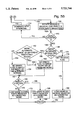
- FIG. 3 is a flow diagram illustrating the operation of the system and method of the present invention to correct burst errors in digital information.
- FIG. 4 is a schematic drawing of an apparatus to correct burst errors in digital information.
- FIG. 5 is a detailed flow diagram of the system and method of burst error correction of FIG. 3.
- FIG. 1 schematically illustrates a commonly used format for encoding transmissions in radio paging applications.
- the format was developed in the 1970s by British Telecom and is known by the acronym POCSAG, for British Post Office Code Standardization Advisory Group.
- POCSAG British Post Office Code Standardization Advisory Group.
- the message transmissions are grouped and transmitted as a sequence of address codes and message codes.
- the code which follows the preamble code in a POCSAG transmission is a series of code groups called batches. Each batch contains a synchronization code followed by a plurality of code words. The duration of a batch is 544-bits, including 32-bit synchronization code word, followed by 16-address code words of 32-bits each.
- Each 32-bit code word comprises one 1-bit (used to distinguish between address and message code words), followed by 18-address bits (where a pager's address is encoded when a message is sent to the pager), followed by two function bits (generally used to specify the type of signaling device employed to alert the user), ten check sum bits (used in error correction of the address bits), and one parity bit (used in error correction of code words by the present invention).
- a message code word is similarly structured; 1-bit (to distinguish between address and message words), followed by 20-message bits, 10-check sum bits, and 1-parity bit.
- each 32-bit POCSAG word is composed of 21-bits of information, 10-bits of error checking, and 1-parity bit.
- the 31-bits comprising the information and error checking bits are the BCH cyclic word.
- BCH formats and cyclic words can be found in the text, "Error Correcting Coding Theory" by Man Young Rhee, McGraw Hill Communication Series, 1989. Every family of BCH cyclic words is derived from a generating polynomial which represents the spacing between words.
- the 31-bit cyclic word presented above is only one possibility among many combinations of information and error checking bits.
- a POCSAG transmission is ultimately concerned with the transmission of 21-bits of information.
- the 10-error checking, or Cyclic Redundancy Check (CRC) bits, following the information bits are generated by amending the information bits with 10-bits of zero numbers. That is, the 21-information bits are shifted 10-bit positions higher in significance and zeros are inserted into the 10-least significant bit positions.
- This 31-bit position word is then divided by the generating polynomial to produce a 10-bit syndrome.
- This syndrome is amended to the 21-information bits to produce a 31-bit word for transmission, as shown in Table 1.
- the numbers in the 31 bit positions of the transmitted words are summed, in modulo 2, to derive the parity of the cyclic word, which is either even or odd.
- the parity information is amended to the 31-bit word in the form of a parity bit in the least significant position. That is, the 31-bit cyclic word is shifted 1-bit position higher in significance and the parity bit is inserted into the least significant bit position, as shown in Table 2-1.
- the 31-bit cyclic word portion is again divided by the generating polynomial to recover the original 21-bits of information.
- the remainder after division is a 10-bit word called the first syndrome. If no error has occurred in the transmission of the 31-bit cyclic word, the syndrome will be all zeros to match the pattern of ten zeros inserted into the ten most insignificant bit positions of the cyclic word before transmission (see Table 1.) Alternately, patterns using other numbers besides ten zeros can be used to create the transmission word. The recovery of this same alternate pattern in the receiver after division of the transmitted word by the generating polynomial indicates the lack of errors in the transmission process.
- Table 2-1 shows a transmitted word, the cyclic word generated in Table 1 with it's amended parity bit.
- Table 2-1 also depicts the corruption of the transmitted word, as three numbers in a burst of 5-bit positions are corrupted. The corrupted word results in the received word.
- Table 2-2 illustrates the process of dividing the received word by the generating polynomial, 21-times, to produce the first syndrome.
- the processing of received, or uncorrected, words in the method of correction using error trapping, generating polynomials, and syndromes to identify and replace errors in uncorrected, or received words, to yield corrected, or processed, words is well known.
- the first syndrome is further divided by the generating polynomial. After each division the remainder is shifted one bit position higher in significance and a zero inserted into the least significant digit. This new syndrome is once again divided by the generating polynomial.
- Table 2-3 shows the process of generating the remaining 30-syndromes.
- bit positions of the received word to which the summing bits are added correspond to the bits positions of the summing bits in the syndrome, and are offset one bit position every time a new syndrome is generated.
- RW(9:5), S(9:5), and CB(9:5) respectively represent received word, syndrome, and corrected burst.
- the numbers inside the parenthesis represent the bit positions in a digital word, and include all the bit positions between the numbers in the parenthesis. For example, RW(9:5) represents bit positions 5, 6, 7, 8, and 9 of the received word.
- Bit positions 5-9 of the syndrome S(9:5) are the summing bits which are added to bit positions 5-9 of the received word RW(9:5), when the locating bits in the syndrome are in bit positions 0-4, S(4:0).
- the corresponding bit positions in the received word shift one position in significance with respect to the bit positions of the summing bits for each syndrome generated thereafter.
- An example of this error trapping process is presented in Tables 2-3, 2-4, 2-5, and 2-6 below.
- Table 2-3 presents the generation of 5-consecutive zero bits in syndrome twenty two.
- the five least significant bit positions of the syndrome, S(4:0) are the locating bits of syndrome twenty two.
- the syndrome is a cyclic word so the highest significant bit position is considered consecutive to the least significant bit. Therefore, 5-consecutive bits can also be considered to be detected in syndromes 17-21. Any of syndromes 17-22 can be used for error trapping, and yield the same end result.
- the locating bits shall be the .left brkt-top.log 2 n.right brkt-top. least significant bit positions of the syndrome.
- the five most significant bits, S(9:5) are the summing bits.
- Table 2-5 shows the summing bits being added to the received word in the receive register to yield an alternate word.
- the five most significant bits in syndrome twenty two are added, in modulo 2, to the numbers in the 5-9 bit positions in the received word to generate the alternate word.
- the alternate word is then loaded into the 1st storage register, before the generation of the twenty third syndrome.
- Table 2-4 shows that the received word is rotated after the generation of every syndrome.
- the word is rotated by inserting the number in the most significant bit position into the least significant bit position, and shifting all the other numbers one bit position higher in significance.
- the received word is rotated as a convenient means of tracking the correspondence between the summing bit and the portion of the received word to which the summing bits are added.
- the summing bits are always added to numbers in the same bit positions of the received word. That is, S(9:5) is always added to RW(9:5).
- the summing bits could be added to the received word through offsetting the bit positions of the received word by the number of syndromes generated.
- summing bits S(9:5) would be added to numbers in the received word bit positions 21-places lower in significance.
- the number twenty one corresponds to the generation of twenty one additional syndromes after the first syndrome. Since the received word is a 31 bit cyclic word, moving 21 places lower in significance is the same as moving 10 positions higher in significance. Therefore, the summing bits S(9:5) would be added to RW(19:15) if the numbers in the receive register were not rotated every time a new syndrome was produced.
- the alternate word once generated must continue to be rotated every time a new syndrome is generated, see Table 2-5.
- Tables 2-4, 2-5, and 2-6 are combined in Table 2-7 to show the simultaneous rotation of the words in the registers with the generation of each new syndrome.
- Table 2 presents an example of a (n-k)-.left brkt-top.log 2 n.right brkt-top.! error burst that is correctable using prior art error trapping techniques.
- Table 3 presents an example of the prior art methods failing to correct a (n-k)-.left brkt-top.log 2 n.right brkt-top.! error burst.
- Table 3-1 shows a 32-bit transmitted word comprising a 31-bit cyclic word, and a parity bit in the least significant bit position. 5-bits in a 5-bit burst pattern are corrupted to yield the received word.
- the received word is divided by the generating polynomial to obtain a first syndrome. New syndromes are produced by dividing the previous syndrome by the generating polynomial, as depicted in Table 3-3. Since the cyclic word has 31-bit positions, thirty one syndromes must be derived to check thirty one different bursts of 5-bit positions. The error trapping process yields a pattern of five zero bits in syndrome six.
- the numbers in the other 5-bit positions of syndrome six, the summing bits S(9:5), are added in modulo 2 to predetermine bit positions in the received word, RW(9:5), as can be seen in Table 3-5.
- the location bits S(4:0) are also all zeros in syndromes four and five. Performing the error correction process on either of these two syndromes yields the same end result as using syndrome six. That is, the correction of the received word with syndrome of four, five, and six all yield the same result. Likewise, performing error trapping with all three syndromes yields the same result.
- the alternate word created by summing S(9:5) with the rotated word RW(9:5) is saved in the first storage register, as shown in Table 3-5.
- the alternate word in the first register is rotated upon the generation of each new syndrome so that the numbers in the bit positions of the alternate word are in the proper order after the generation of the last syndrome.
- a second pattern of zeros, independent of the first detected pattern is found in syndromes 9-14. Any of syndromes 9-14 can be used to yield the same alternate word.
- a syndrome with the zero bits in the least significant positions of the syndrome, S(4:0), is used.
- Summing bits S(9:5) of syndrome fourteen are added to the rotating received word, in Table 3-6, to create an alternate word which is stored in the second storage register.
- the second alternate word is rotated upon the generation of each new syndrome.
- FIG. 3 shows a flow diagram illustrating the system and method of the present invention of correcting burst errors digital information.
- the received or uncorrected words are accepted at a step 14.
- Line 16 joins step 14 to a step 18 of accepting parity information about the received or uncorrected word.
- Line 20 joins step 18 to the step 22 of searching by error trapping for a first burst of up to (n-k)-.left brkt-top.log 2 n.right brkt-top.! bit positions in each uncorrected word and producing a first alternate word therefrom.
- step 22 is the searching by error trapping for the bit positions of a burst error of up to (n-k)-.left brkt-top.log 2 n.right brkt-top.! bit positions in the received word, producing an alternate word therefrom, and measuring the parity of the alternate word.
- step 22 is the searching by error trapping for the bit positions of bursts of up to 5-bit positions (in the POCSAG format) in each received word to produce a first parity alternate word.
- Step 22 is equivalent to the process, in Tables 3-3, 3-4, and 3-5, of locating an error in the sixth syndrome and the creation of the first alternate word in the first storage register.
- the (same) first alternate word can be generated for several successive syndromes.
- the first alternate word is equivalent to a first parity word, or an alternate word produced form a first burst error.
- a line 24 joins step 22 to a step 26 of searching by error trapping for a second burst of up to (n-k)-.left brkt-top.log 2 n.right brkt-top.! bit positions in each uncorrected word, and if such a second burst is found, to produce a second alternate word therefrom.
- step 26 is repeating the error trapping procedures for all n possible bit positions of the received word, producing up to n alternate words therefrom, and making up to n parity measurements of the alternate words.
- step 26 is the searching by error trapping for the bit positions of bursts of up to 5-bit positions (in the POCSAG format) in each received word to produce a second parity alternate word.
- Step 26 is equivalent to the process, in Tables 3-3, 3-4, and 3-6, of locating an error in the fourteenth syndrome and the creation of a second alternate word in the second storage register.
- the remaining steps in the method illustrated in FIG. 3 allow the correct word to be selected from among the two alternate words in the two storage registers, and go to the heart of the present invention.
- the second alternate word can be produced by several successive syndromes. The distinguishing difference between first and second alternate words is their differing parities, and the second alternate word is equivalent to the second parity alternate word.
- a line 28 joins step 26 to step 30, where it is determined whether a second burst error of up to (n-k)-.left brkt-top.log 2 n.right brkt-top.! bit positions is found in step 26 (two alternate words produced). If not, then a line 32 is used to connect step 30 to a step 34 that chooses the first alternate word as the corrected word when no second burst error is found. Alternately, it can be said that when only one type of parity is measured in the production of alternate words, then line 32 is followed to connect step 30 to step 34 which selects any alternate word as the processed word.
- step 34 Yet another alternate statement of step 34 is that when (POCSAG) alternate words are produced in step 22, but not step 26, selecting the last produced alternate word as the processed word.
- This step is equivalent to the process, in Table 2, of selecting the alternate word in the first storage register when only one alternate word is produced by the error trapping process.
- step 38 connects step 38 to a step that selects any alternate word with parity matching the parity information for the received, or uncorrected, word as the corrected word. Alternately, it can be said that step 38 selects as the corrected word, whichever of the first and second alternate words has a parity corresponding to the parity information of the uncorrected word. Yet another alternative statement of step 38 is that when alternate words are produced in steps 22 and 26, selecting the last produced alternate word having the parity of the received (POCSAG) word parity bit. Line 40 joins steps 34 and steps 38 to the finish of the process 42.
- the 32nd, or parity bit, of the POCSAG word is used to provide the parity information for the received word.
- Non-POCSAG systems can also use a parity bit to supply the parity information.
- the parity information could be received through other communication channels, or the system could use only words of a single, known, parity.
- FIG. 4 is a schematic diagram of the apparatus to correct burst errors in digital information.
- Uncorrected (received words), including POCSAG words are accepted on a line 44.
- this information is in a serial format with the most significant bit of the data words being received first in time. Alternately, the received words can be received in parallel format.
- the cyclic word portion of the received word is accepted into a receive register 46 and a syndrome generator 48.
- the 31-bit cyclic word is accepted by receive register 46 and syndrome generator 48, but not the 32nd (parity) bit.
- the parity bit or parity information on line 44 is received by parity logic device 50.
- a parity bit or parity information can be supplied to parity logic device 50 from sources other than line 44.
- syndrome generator 48 Upon receiving the complete received cyclic word, syndrome generator 48 derives n syndromes, of (n-k) bit positions, for the purpose of error trapping. Upon finding a pattern of .left brkt-top.log 2 n.right brkt-top. consecutive zero bits in the least significant bit positions of the syndrome, the summing bits, or the remaining bits of the syndrome are output on a line 52. In terms of the POCSAG format, 31-syndromes are generated, each syndrome comprising 10-bit positions. When the 5-least significant digits in the syndrome are zeros, the 5-most significant bits are output on a line 52 as summing bits to the XOR summing circuit 54.
- summing circuit 54 accepts numbers from (n-k)-.left brkt-top.log 2 n.right brkt-top.! predetermined bit positions of the received word.
- bit positions five through nine of the received word, RW(9:5) are input to summing circuit 54 on a line 56.
- Receive register 46 rotates the received word simultaneously with searching for the alternate words by error trapping through the generation of each new syndrome. In this manner, the potential error bits always occur in bit positions five through nine of the rotated received word.
- the received word, in received register 46 is rotated as the method of maintaining a pointer to the error bit positions in the received word. This rotation method reduces the number of gates needed to perform the pointing process.
- Summing circuit 54 adds the summing bits on line 52 with the received word bits on line 56, in modulo 2, and outputs a corrected burst of (n-k)-.left brkt-top.log 2 n.right brkt-top.! bit positions on a line 58.
- the corrected burst is 5-bit positions.
- the rotated received word on line 56, RW(30:0) and the corrected burst, CB(9:5), on line 58 are input to a parity generator 60. Parity generator 60 inserts the (n-k)-.left brkt-top.log 2 n.right brkt-top.!
- Parity generator 60 then sums the numbers in the bit positions of the alternate word, in modulo 2, to produce the parity of the alternate word. If the parity of the alternate word is odd, a parity output sum is output on a line 62 to supply the parity logic device 50. If the parity of the alternate word is even, an even parity sum is output on a line 64 to supply parity logic device 50. Parity generator 60 operatively controls the loading of the parity registers with alternate words having the matching parity so that alternate words with odd parity are received into the odd parity register and alternate words with even parity are received into the even parity register, as described below.
- the received word on line 56 and the corrected burst on line 58 are input to at least one register where alternate words and their respective parity can be tracked and stored. Preferably, separate registers are provided for alternate words of each parity.
- the rotated received, or uncorrected, word on line 56 is input to an even parity register 66 and an odd parity register 68.
- the corrected burst on line 58 is, likewise, input to even parity register 66 and odd parity register 68. Simultaneously with the generation of an odd parity sum on line 62, odd parity register 68 is enabled to accept the received word input on line 56 and corrected burst input on line 58.
- the numbers in the corrected burst are inserted into the predetermined (error bit) positions of the uncorrected word to generate an alternate word.
- CB(9:5) is inserted into RW(9:5) to generate an alternate word.
- the alternate word generated in odd parity register 68 is also stored in register 68, and rotated with the generation of each new syndrome by syndrome generator 48 simultaneously with the rotation of numbers in the receive register. The rotation of the alternate word in the odd parity register provides the correct ordering of the numbers in the bit positions of the alternate word for use as the corrected word with a minimum use of logic gates.
- even parity register 66 is enabled to accept the rotated received word on line 56 and the corrected burst on line 58.
- odd parity register 68 the numbers in the corrected burst are inserted into the corresponding bit positions of the rotated received word to produce an alternate word.
- the alternate word is stored in even register 66 and rotated simultaneously with the numbers in the receive register as each new syndrome is generated by syndrome generator 48.
- Parity logic device 50 produces a parity flag and received flag upon the completion of n syndromes. In the POCSAG format, parity logic device 50 produces flag outputs after thirty one syndromes are generated. If parity logic device 50 receives only odd parity sums on line 62 (when the alternate words have only odd parity), then parity logic device 50 will set the parity flag on line 70 to odd. An odd parity flag on line 70, indicating odd parity, will enable a final latch 72. Upon being enabled by the odd parity flag on line 70, final latch 72 loads the output of odd parity register 68 supplied on line 74. Final latch 72 then supplies the alternate word loaded from odd parity register 68 on a line 76 as the processed, or corrected, word.
- parity logic device 50 receives only even parity sums on line 64 (when the alternate words have only even parity), then parity logic device 50 sets the parity flag on line 70 to even.
- parity flag on line 70 is even, indicating even parity, final latch 72 is enabled to accept the output of even parity register 66 on a line 78.
- Final latch 72 then supplies the alternate word from even parity register 66 as the processed word on line 76.
- parity generator 60 When parity generator 60 outputs both even and odd parity sums on line 62 and 64 (when the alternate words have both even and odd parity), the parity bit information input on line 44 to parity logic device 50 is used. This situation is equivalent to the generation of alternate words in the first and second storage registers in Tables 3-5 and 3-6, above.
- the processed word For the processed word to be correct, the processed word must have a parity corresponding to that parity bit, or parity information, received by parity logic device 50 on line 44. Therefore, the alternate word having the same parity as the received parity bit, or the alternate word with parity matching the parity information for the received word, is selected as the processed word on line 76.
- parity logic device 50 sets the parity flag on line 70 to odd so that the alternate word in the odd parity register 68 is selected as the processed word.
- parity logic device 50 sets the parity flag on line 70 to even so that the alternate word in the even parity register 66 is selected as the processed word. It is possible in the communication of data, that the parity bit, or parity information, on line 44 can be received in a corrupted form. To minimize the chance of an incorrect alternate word being selected as the result of a corrupted parity bit, the parity bit is used, in the present invention, to select the processed word only when two alternate words are produced.
- parity generator 60 produces neither odd nor even sum outputs on line 62 or 64.
- parity logic device 50 receives neither odd nor even parity sum outputs (no parity sums) it supplies a received flag (the receive flag is enabled) on a line 80 to final latch 72.
- final latch 72 accepts the received flag, the rotated received word on line 56 is loaded into final latch 72 and output as the processed word on line 76. That is, the received word is used as the corrected word without any corrections.
- the received word on line 44 When the received word on line 44 is correct, then all the syndromes generated will be composed of zeros in both the locating bit positions and the summing bit positions. Therefore, the error trapping process will occur with respect to every syndrome. However, since the summing bits are all zeros, the alternate words are the same as the rotated received words. Also, every alternate word will have the same parity, the parity of the received word.
- the n alternate words may be kept in n separate registers and rotated with the generation of each new syndrome. Upon completing the generation of the n syndromes, any of the n alternate words may be used as the corrected word since all the alternate words are the same. Alternately, a single register may be used to reduce the number of gates required. Each new alternate word can be inserted into the register to replace the old word in the register since the new and old words are identical.
- the method and apparatus of the present invention may generate multiple syndromes with zeros in the location bits to yield the same alternate word.
- syndromes four through six all have zeros in the locating bit positions, S(4:0), of the syndrome.
- the apparatus of FIG. 4 error traps for each of these three syndromes. All three alternate words have the same parity, and are therefore, stored in the same register. After rotation, all three alternate words are identical. Therefore, it is irrelevant that the alternate word generated by syndrome five replaces, or eliminates, the alternate word generated by syndrome four. Likewise, it is irrelevant that the alternate word generated by syndrome six replaces the alternate word generated by syndrome five.
- a single register may be used for each parity and the last generated alternate word may be stored over any previously generated alternate words. That is, alternate words with even parity are stored in the even parity register, eliminating the previously stored alternate words, and alternate words with odd parity are stored in the odd parity registers, eliminating the previously stored alternate words.
- the 1st register contains the first alternate word regardless of how many alternate words of the same parity were produced by the error trapping process.
- a first alternate word is related to a first burst error of up to (n-k).left brkt-top.log 2 n.right brkt-top.! bit positions, even if other alternate words of the same parity are created by other error bursts. Further, it can be said that the first alternate word corresponds to a first parity alternate word.
- a single, 2nd, register which accepts only alternate words of a different parity from those accepted by the first register, contains the second alternate word, regardless of how many alternate words are loaded into it.
- a second alternate word is related to a second burst error of up to (n-k)-.left brkt-top.log 2 n.right brkt-top.! bit positions, even if several alternate words of the same parity are created from several burst error corrections. Since, by the method of the present invention, a register is provided for alternate words of each parity type, and two parities exist, it can be said that the first and second alternate words have opposite parity. Likewise, even and odd parity alternate words correspond to first and second parity alternate words.
- FIG. 5 illustrates a detailed flow diagram of the system and method of burst error correction of FIG. 3.
- the method of processing received digital information starts at step 82.
- Step 82 is connected with a line 84 to a step 86 to receive augmented (n+1l) words comprising an uncorrected (n,k) cyclic word and a parity bit, or to receive cyclic words with the parity information being supplied from an independent source.
- a line 88 connects step 86 to step 90 where the cyclic part of the received word is loaded into the receive register.
- a line 92 joins step 90 to a step 94 where the parity bit of the received word is loaded into a parity logic device.
- a line 96 joins step 94 to a step 98 where the first syndrome is generated.
- a line 100 joins step 98 to a step 102 where it is determined whether all the location bits in the syndrome are zero.
- the .left brkt-top.log 2 n.right brkt-top. location bits are used as a pointer to identify the positions in the received cyclic word with potential errors.
- the 31-bit cyclic word of the POCSAG format there are 5-locating bits in the ten bit syndrome.
- step 104 is followed to step 106 where the numbers and the bit positions of the received word in the receive register, and the alternate words in the odd and even parity registers, are rotated.
- a line 108 joins step 106 to a step 110 where it is determined if a counter is equal to n, the number of cyclic bit positions. That is, have n syndrome words been generated? In the POCSAG format, it is determined whether thirty one syndromes have been generated. If not, line 112 is followed to a step 114 where a new syndrome is generated.
- a line 116 joins step 114 to a step 118 where the counter is incremented.
- a line 120 is used to join step 118 to step 102 which, once again, determines if a predetermined pattern of zeros exists in the location bits of the syndrome word.
- line 122 is used to join step 102 to a step 124 where the (n-k)-.left brkt-top.log 2 n.right brkt-top.! number of summing bits are added, in modulo 2, to the error bit positions of the uncorrected word corresponding to the bit positions of the locating bits to generate a corrected burst of (n-k)-.left brkt-top.log 2 n.right brkt-top.! bit positions.
- S(9:5) is added, in modulo 2, to RW(9:5) to produce CB(9:5).
- a line 126 joins step 124 to a step 128 where the corrected burst, generated in step 124, is inserted into predetermined bit positions of the received word to produce an alternate word.
- CB(9:5) is inserted into RW(9:5) to produce an alternate word.
- a line 130 joins step 128 to a step 132 where the parity of the alternate word is checked. That is, the numbers in the bit positions of the first and second (even and odd) alternate words are summed to derive the parity of each word. The result, called the parity sum output, is loaded into a parity logic device. Alternately, it can be said that step 132 checks a parity output indicating the parity of each alternate word, which parity output is used in matching the parity of each alternate word to the parity register having the corresponding parity (see step 136.)
- a line 134 joins step 132 to a step 136 where it is determined whether the parity calculated in step 132 is odd. If the parity is odd, then a line 138 is followed to a step 140 where the corrected burst and received word are loaded into an odd parity register so that the corrected burst replaces numbers in predetermined bit positions of the received word to produce an alternate word.
- CB(9:5) is inserted into bit positions 5 through 9 of the received word, RW(9:5), to produce the odd parity alternate word.
- step 136 If, in step 136, it is determined that the parity is not odd, then a line 142 is followed to a step 144 where the corrected burst and received word are loaded into an even parity register to produce an alternate word, in a manner similar to the process explained in step 140 above. Alternately, it can be said about steps 140 and 144, that first and second alternate words are produced (in the parity registers) by inserting the corrected burst into (potential) error bit positions of the received, or uncorrected, word.
- Line 104 joins steps 144 and 140 to step 106 where the words in the receive register, odd parity register, and even parity register are rotated.
- step 110 When the counter in step 110 equals n, then a line 146 is followed to a step 148 where it is determined whether alternate words were produced. Alternately, it can be determined whether parity sum outputs were generated, since no parity sums outputs are produced unless alternate words are produced.
- step 148 If it is determined in step 148 that alternate words were produced, then a line 150 is followed to a step 152 where it is determined whether alternate words of different parities were produced. If no alternate words of different parity were produced, then only alternate words of the same parity were produced. In the event that all the alternate words have the same parity, a line 154 is followed to a step 156 in which a parity flag is set to match the parity of the alternate words produced. That is, if only even parity words are produced then the even parity flag is set. Likewise, if only odd parity alternate words are produced, then the odd parity flag is set.
- step 152 If, in step 152, it is determined that alternate words of different parties were produced, a line 158 is followed to a step 160 where a parity flag is set to match the parity information for the received word.
- the 32nd-bit is the parity bit. This parity bit is used set the parity flag in step 180.
- a line 162 joins step 156 and step 160 to a step 164 where it is determined whether the parity flag, set in either step 156 or 160, is odd. If the parity is odd, then a line 166 is followed to a step 168 where the word in the odd parity register is loaded as the corrected or the processed word. If it is determined in step 164 that the parity is even, then a line 170 is followed to a step 172 where the word in the even parity register is loaded as the processed word.
- step 148 If, in step 148, it is determined that no alternate words were produced, then a line 174 is followed to a step 176 where the received flag is set. A line 178 joins step 176 to a step 180 where the word in the receive register is loaded as the processed word in response to the receive flag. A line 182 joins steps 172, 168, and 180 to the finish process step 184.
- the system and method of the present invention provides an improved technique for correcting burst errors in cyclic words.
- the invention uses independently obtained parity information, or an additional parity bit, to always correct a cyclic word, including those found in BCH codebooks or systems, having n total bits, k information bits, and burst errors up to (n-k)-.left brkt-top.log 2 n.right brkt-top.! bit positions.
- the prior art method of burst error correction does not always correct burst errors of (n-k)-.left brkt-top.log 2 n.right brkt-top.! bit positions.
- the parity information is used to differentiate between two alternate words generated as possible corrections to a received word.
- the POCSAG format especially benefits from the implementation of this invention.
- the 32nd-bit, or parity bit is not used.
- the method of the present invention uses this parity bit as an additional error checking bit.
- the present invention allows a POCSAG pager receiver to always correct 5-burst errors, as opposed to only 4-burst errors with the prior art method. By increasing the possibility that a received message will be correctly decoded in a receiver, the present method improves the likelihood that the user will receive the intended message.
- the present invention selects the processed word, without reference to the parity information of the received word, when an alternate word, or words, of only one parity are produced. Only when alternate words of different parity are produced, is the parity bit checked to select the processed word.
- the present invention is useful, outside of the POCSAG format, in situations where parity information can be obtained from sources independent of the received word. For example, in situations where the received word is received via an airlink on a first channel, the parity information can be received on a second channel. Alternately, digital information systems can be designed to use only words of one parity, even parity for example, so that the parity information is known to be even.
- Alternate embodiments of the above described system and method for correcting burst errors in digital information can be applied to any system of digital communication.
- the method is especially applicable to systems where reliable communication is a necessity.
- the method of the present invention is also useful as a basis for creating software based systems using a computer program and microprocessor to correct burst errors of up to (n-k)-.left brkt-top.log 2 n.right brkt-top.! bit positions in a (n,k) cyclic word.
- Other modifications and variations within the scope of the present invention will occur to those skilled in the art.
Abstract
Description
              TABLE 1
______________________________________
 ##STR1##
 ##STR2##
 ##STR3##
1111 0101 000
 ##STR4##
001 1000 0011
 ##STR5##
01 1000 0011 0
 ##STR6##
1 1000 0011 00
 ##STR7##
0101 1001 011
 ##STR8##
101 1001 0111
 ##STR9##
10 1111 1110 1
 ##STR10##
1 0100 1010 00
 ##STR11##
1001 0000 010
 ##STR12##
111 1101 0110
 ##STR13##
00 1011 1111 0
 ##STR14##
0 1011 1111 00
 ##STR15##
1011 1111 000
 ##STR16##
101 0010 0010
 ##STR17##
10 0100 1011 0
 ##STR18##
1 1111 1111 10
 ##STR19##
0010 0101 110
 ##STR20##
010 0101 1100
 ##STR21##
10 0101 1100 0
 ##STR22##
1 1110 1000 10
 ##STR23##
0011 0010 11
0011 0010 11Syndrome (check sum):
______________________________________
              TABLE 2-1
______________________________________
Transmitted codeword:
             011 1101 0100 0100 1110 0000 1100 1011 1
Corrupted bits:
                    1100 1
Received codeword:
             011 1101 0100 1000 0110 0000 1100 1011 1
______________________________________
              TABLE 2-2
______________________________________
 ##STR24##
 ##STR25##
11 1101 0100 1
 ##STR26##
0 0110 0000 00
 ##STR27##
0110 0000 000
 ##STR28##
110 0000 0000
 ##STR29##
01 0110 1001 0
 ##STR30##
1 0110 1001 01
 ##STR31##
1011 0011 001
 ##STR32##
101 1110 0000
 ##STR33##
10 1000 1001 0
 ##STR34##
1 0011 1101 10
 ##STR35##
1110 0111 110
 ##STR36##
000 1010 1110
 ##STR37##
00 1010 1110 1
 ##STR38##
0 1010 1110 11
 ##STR39##
1010 1110 110
 ##STR40##
100 0011 1110
 ##STR41##
11 0101 0111 1
 ##STR42##
0 1110 0011 00
 ##STR43##
1110 0011 001
 ##STR44##
000 1110 0001
 ##STR45##
00 1110 0001First Syndrome:
______________________________________
              TABLE 2-3
______________________________________
 ##STR46##
 ##STR47##
 ##STR48##
 ##STR49##
 ##STR50##
 ##STR51##
 ##STR52##
 ##STR53##
 ##STR54##
 ##STR55##
 ##STR56##
 ##STR57##
 ##STR58##
 ##STR59##
 ##STR60##
 ##STR61##
 ##STR62##
 ##STR63##
 ##STR64##
 ##STR65##
 ##STR66##
 ##STR67##
 ##STR68##
 ##STR69##
 ##STR70##
 ##STR71##
______________________________________
              TABLE 2-4
______________________________________
Received Codeword Register Contents
______________________________________
1.       011 1101 0100 1000 0110 0000 1100 1000
2.       111 1010 1001 0000 1100 0001 1001 0110
3.       111 0101 0010 0001 1000 0011 0010 1101
4.       110 1010 0100 0011 0000 0110 0101 1011
5.       101 0100 1000 0110 0000 1100 1011 0111
6.       010 1001 0000 1100 0001 1001 0110 1111
7.       101 0010 0001 1000 0011 0010 1101 1110
8.       010 0100 0011 0000 0110 0101 1011 1101
9.       100 1000 0110 0000 1100 1011 0111 1010
10.      001 0000 1100 0001 1001 0110 1111 0101
11.      010 0001 1000 0011 0010 1101 1110 1010
12.      100 0011 0000 0110 0101 1011 1101 0100
13.      000 0110 0000 1100 1011 0111 1010 1001
14.      000 1100 0001 1001 0110 1111 0101 0010
15.      001 1000 0011 0010 1101 1110 1010 0100
16.      011 0000 0110 0101 1011 1101 0100 1000
17.      110 0000 1100 1011 0111 1010 1001 0000
18.      100 0001 1001 0110 1111 0101 0010 0001
19.      000 0011 0010 1101 1110 1010 0100 0011
20.      000 0110 0101 1011 1101 0100 1000 0110
21.      000 1100 1011 0111 1010 1001 0000 1100
22.      001 1001 0110 1111 0101 0010 0001 1000
23.      011 0010 1101 1110 1010 0100 0011 0000
24.      110 0101 1011 1101 0100 1000 0110 0000
25.      100 1011 0111 1010 1001 0000 1100 0001
26.      001 0110 1111 0101 0010 0001 1000 0011
27.      010 1101 1110 1010 0100 0011 0000 0110
28.      101 1011 1101 0100 1000 0110 0000 1100
29.      011 0111 1010 1001 0000 1100 0001 1001
30.      110 1111 0101 0010 0001 1000 0011 0010
31.      101 1110 1010 0100 0011 0000 0110 0101
______________________________________
TABLE 2-5 __________________________________________________________________________ First Storage Register __________________________________________________________________________ XXX XXXX XXXX XXXX XXXX XXXX XXXX XXXX XXX XXXX XXXX XXXX XXXX XXXX XXXX XXXX XXX XXXX XXXX XXXX XXXX XXXX XXXX XXXX XXX XXXX XXXX XXXX XXXX XXXX XXXX XXXX XXX XXXX XXXX XXXX XXXX XXXX XXXX XXXX XXX XXXX XXXX XXXX XXXX XXXX XXXX XXXX XXX XXXX XXXX XXXX XXXX XXXX XXXX XXXX XXX XXXX XXXX XXXX XXXX XXXX XXXX XXXX XXX XXXX XXXX XXXX XXXXXXXX XXXX XXXX 10. XXX XXXX XXXX XXXX XXXX XXXX XXXX XXXX XXX XXXX XXXX XXXX XXXX XXXX XXXX XXXX XXX XXXX XXXX XXXX XXXX XXXX XXXX XXXX XXX XXXX XXXX XXXX XXXX XXXX XXXX XXXX XXX XXXX XXXX XXXX XXXX XXXX XXXX XXXX XXX XXXX XXXX XXXX XXXX XXXX XXXX XXXX XXX XXXX XXXX XXXX XXXX XXXX XXXX XXXX XXX XXXX XXXX XXXX XXXX XXXX XXXX XXXX XXX XXXX XXXX XXXX XXXX XXXX XXXX XXXX XXX XXXX XXXX XXXX XXXXXXXX XXXX XXXX 20. XXX XXXX XXXX XXXX XXXX XXXX XXXX XXXX XXX XXXX XXXX XXXX XXXX XXXX XXXX XXXX 001 1001 0110 1111 0101 0010 0001 1000 (rotated received word) .sup. 11 001 (summing bits) 001 1001 0110 1111 0101 0001 0011 1000 011 0010 1101 1110 1010 0010 0111 0000 110 0101 1011 1101 0100 0100 1110 0000 100 1011 0111 1010 1000 1001 1100 0001 001 0110 1111 0101 0001 0011 1000 0011 010 1101 1110 1010 0010 0111 0000 0110 101 1011 1101 0100 0100 1110 0000 1100 011 0111 1010 1000 1001 1100 0001 1001 30. 110 1111 0101 0001 0011 1000 0011 0010 101 1110 1010 0010 0111 0000 0110 0101 011 1101 0100 0100 1110 0000 1100 1011 (final alternate word) __________________________________________________________________________
TABLE 2-6 ______________________________________ Second Storage Register ______________________________________ 1. XXX XXXX XXXX XXXX XXXXXXXX XXXX XXXX 2. XXX XXXX XXXX XXXX XXXX XXXX XXXX XXXX 3. XXX XXXX XXXX XXXX XXXX XXXX XXXX XXXX 4. XXX XXXX XXXX XXXX XXXXXXXX XXXX XXXX 5. XXX XXXX XXXX XXXX XXXXXXXX XXXX XXXX 6. XXX XXXX XXXX XXXX XXXXXXXX XXXX XXXX 7. XXX XXXX XXXX XXXX XXXXXXXX XXXX XXXX 8. XXX XXXX XXXX XXXX XXXXXXXX XXXX XXXX 9. XXX XXXX XXXX XXXX XXXXXXXX XXXX XXXX 10. XXX XXXX XXXX XXXX XXXX XXXX XXXX XXXX 11. XXX XXXX XXXX XXXX XXXXXXXX XXXX XXXX 12. XXX XXXX XXXX XXXX XXXX XXXX XXXX XXXX 13. XXX XXXX XXXX XXXX XXXXXXXX XXXX XXXX 14. XXX XXXX XXXX XXXX XXXX XXXX XXXX XXXX 15. XXX XXXX XXXX XXXX XXXXXXXX XXXX XXXX 16. XXX XXXX XXXX XXXX XXXX XXXX XXXX XXXX 17. XXX XXXX XXXX XXXX XXXXXXXX XXXX XXXX 18. XXX XXXX XXXX XXXX XXXX XXXX XXXX XXXX 19. XXX XXXX XXXX XXXX XXXXXXXX XXXX XXXX 20. XXX XXXX XXXX XXXX XXXX XXXX XXXX XXXX 21. XXX XXXX XXXX XXXX XXXXXXXX XXXX XXXX 22. XXX XXXX XXXX XXXX XXXX XXXX XXXX XXXX 23. XXX XXXX XXXX XXXX XXXXXXXX XXXX XXXX 24. XXX XXXX XXXX XXXX XXXX XXXX XXXX XXXX 25. XXX XXXX XXXX XXXX XXXXXXXX XXXX XXXX 26. XXX XXXX XXXX XXXX XXXX XXXX XXXX XXXX 27. XXX XXXX XXXX XXXX XXXXXXXX XXXX XXXX 28. XXX XXXX XXXX XXXX XXXX XXXX XXXX XXXX 29. XXX XXXX XXXX XXXX XXXXXXXX XXXX XXXX 30. XXX XXXX XXXX XXXX XXXX XXXX XXXX XXXX 31. XXX XXXX XXXX XXXX XXXX XXXX XXXX XXXX ______________________________________
TABLE 2-7
  -
  ##STR72##
                                                                          0
  1.XXXXXXXXXXXXXXXXXXXXXXXXXXXXXXXXXXXXXXXXXXXXXXXXXXXXXXXXXXXXXX01111011
 0010000110000011001011
  2.XXXXXXXXXXXXXXXXXXXXXXXXXXXXXXXXXXXXXXXXXXXXXXXXXXXXXXXXXXXXXX111101010
 0100001100000110010110
  3.XXXXXXXXXXXXXXXXXXXXXXXXXXXXXXXXXXXXXXXXXXXXXXXXXXXXXXXXXXXXXX111010100
 1000011000001100101101
  4.XXXXXXXXXXXXXXXXXXXXXXXXXXXXXXXXXXXXXXXXXXXXXXXXXXXXXXXXXXXXXX110101001
 0000110000011001011011
  5.XXXXXXXXXXXXXXXXXXXXXXXXXXXXXXXXXXXXXXXXXXXXXXXXXXXXXXXXXXXXXX101010010
 0001100000110010110111
  6.XXXXXXXXXXXXXXXXXXXXXXXXXXXXXXXXXXXXXXXXXXXXXXXXXXXXXXXXXXXXXX010100100
 0011000001100101101111
  7.XXXXXXXXXXXXXXXXXXXXXXXXXXXXXXXXXXXXXXXXXXXXXXXXXXXXXXXXXXXXXX101001000
 0110000011001011011110
  8.XXXXXXXXXXXXXXXXXXXXXXXXXXXXXXXXXXXXXXXXXXXXXXXXXXXXXXXXXXXXXX010010000
 1100000110010110111101
  9.XXXXXXXXXXXXXXXXXXXXXXXXXXXXXXXXXXXXXXXXXXXXXXXXXXXXXXXXXXXXXX100100001
 1000001100101101111010
                                                                          1
 0.XXXXXXXXXXXXXXXXXXXXXXXXXXXXXXXXXXXXXXXXXXXXXXXXXXXXXXXXXXXXXX001000011
 0000011001011011110101
                                                                          1
 1.XXXXXXXXXXXXXXXXXXXXXXXXXXXXXXXXXXXXXXXXXXXXXXXXXXXXXXXXXXXXXX010000110
 0000110010110111101010
                                                                          1
 2.XXXXXXXXXXXXXXXXXXXXXXXXXXXXXXXXXXXXXXXXXXXXXXXXXXXXXXXXXXXXXX100001100
 0001100101101111010100
                                                                          1
 3.XXXXXXXXXXXXXXXXXXXXXXXXXXXXXXXXXXXXXXXXXXXXXXXXXXXXXXXXXXXXXX000011000
 0011001011011110101001
                                                                          1
 4.XXXXXXXXXXXXXXXXXXXXXXXXXXXXXXXXXXXXXXXXXXXXXXXXXXXXXXXXXXXXXX000110000
 0110010110111101010010
                                                                          1
 5.XXXXXXXXXXXXXXXXXXXXXXXXXXXXXXXXXXXXXXXXXXXXXXXXXXXXXXXXXXXXXX001100000
 1100101101111010100100
                                                                          1
 6.XXXXXXXXXXXXXXXXXXXXXXXXXXXXXXXXXXXXXXXXXXXXXXXXXXXXXXXXXXXXXX011000001
 1001011011110101001000
                                                                          1
 7.XXXXXXXXXXXXXXXXXXXXXXXXXXXXXXXXXXXXXXXXXXXXXXXXXXXXXXXXXXXXXX110000011
 0010110111101010010000
                                                                          1
 8.XXXXXXXXXXXXXXXXXXXXXXXXXXXXXXXXXXXXXXXXXXXXXXXXXXXXXXXXXXXXXX100000110
 0101101111010100100001
                                                                          1
 9.XXXXXXXXXXXXXXXXXXXXXXXXXXXXXXXXXXXXXXXXXXXXXXXXXXXXXXXXXXXXXX000001100
 1011011110101001000011
                                                                          2
 0.XXXXXXXXXXXXXXXXXXXXXXXXXXXXXXXXXXXXXXXXXXXXXXXXXXXXXXXXXXXXXX000011001
 0110111101010010000110
                                                                          2
 1.XXXXXXXXXXXXXXXXXXXXXXXXXXXXXXXXXXXXXXXXXXXXXXXXXXXXXXXXXXXXXX000110010
 1101111010100100001100
  ##STR73##
              TABLE 3-1
______________________________________
                             P
______________________________________
Transmitted codeword:
             011 1101 0100 0100 1110 0000 1100 1011 1
Corrupted bits:
                1111 1
Received codeword:
             011 0010 1100 0100 1110 000 1100 1011 1
______________________________________
              TABLE 3-2
______________________________________
 ##STR74##
 ##STR75##
 ##STR76##
 ##STR77##
 ##STR78##
 ##STR79##
 ##STR80##
 ##STR81##
 ##STR82##
 ##STR83##
 ##STR84##
 ##STR85##
 ##STR86##
 ##STR87##
 ##STR88##
 ##STR89##
 ##STR90##
 ##STR91##
 ##STR92##
 ##STR93##
 ##STR94##
______________________________________
              TABLE 3-3
______________________________________
 ##STR95##
 ##STR96##
 ##STR97##
 ##STR98##
 ##STR99##
 ##STR100##
 ##STR101##
 ##STR102##
 ##STR103##
 ##STR104##
 ##STR105##
 ##STR106##
 ##STR107##
 ##STR108##
 ##STR109##
 ##STR110##
 ##STR111##
 ##STR112##
 ##STR113##
 ##STR114##
 ##STR115##
 ##STR116##
 ##STR117##
 ##STR118##
 ##STR119##
 ##STR120##
31.00 0000 1010
______________________________________
              TABLE 3-4
______________________________________
Received Codeword Register Contents
______________________________________
1.    011 0010 1100 0100 1110 0000 1100 1011
2.    110 0101 1000 1001 1100 0001 1001 0110
3.    100 1011 0001 0011 10000 0011 0010 1101
4.    001 0110 0010 0111 0000 0110 0101 1011
5.    010 1100 0100 1110 0000 1100 1011 0110
6.    101 1000 1001 1100 0001 1001 0110 1100
7.    011 0001 0011 1000 0011 0010 1101 1001
8.    110 0010 0111 0000 0110 0101 1011 0010
9.    100 0100 1110 0000 1100 1011 0110 0101
10.   000 1001 1100 0001 1001 0110 1100 1011
11.   001 0011 10000 0011 0010 1101 1001 0110
12.   010 0111 0000 0110 0101 1011 0010 1100
13.   100 1110 0000 1100 1011 0110 0101 1000
14.   001 1100 0001 1001 0110 1100 1011 0001
15.   011 1000 0011 0010 1101 1001 0110 0010
16.   111 0000 0110 0101 1011 0010 1100 0100
17.   110 0000 1100 1011 0110 0101 1000 1001
18.   100 0001 1001 0110 1100 1011 0001 0011
19.   000 0011 0010 1101 1001 0110 0010 0111
20.   000 0110 0101 1011 0010 1100 0100 1110
21.   000 1100 1011 0110 0101 1000 1001 1100
22.   001 1001 0110 1100 1011 0001 0011 1000
23.   011 0010 1101 1001 0110 0010 0111 0000
24.   110 0101 1011 0010 1100 0100 1110 0000
25.   100 1011 0110 0101 1000 1001 1100 0001
26.   001 0110 1100 1011 0001 0011 1000 0011
27.   010 1101 1001 0110 0010 0111 0000 0110
28.   101 1011 0010 1100 0100 1110 0000 1100
29.   011 0110 0101 1000 1001 1100 0001 1001
30.   110 1100 1011 0001 0011 10000 0011 0010
31.   101 1001 0110 0010 0111 00000 0110 0101
______________________________________
                                  TABLE 3-5
__________________________________________________________________________
First Storage Register
__________________________________________________________________________
  XXX XXXX XXXX XXXX XXXX XXXX XXXX XXXX
  XXX XXXX XXXX XXXX XXXX XXXX XXXX XXXX
  XXX XXXX XXXX XXXX XXXX XXXX XXXX XXXX
  XXX XXXX XXXX XXXX XXXX XXXX XXXX XXXX
  XXX XXXX XXXX XXXX XXXX XXXX XXXX XXXX
  101 1000 1001 1100 0001 1001 0110 1100
                           (rotated received word)
              .sup.11 10 100
                           (summing bits)
  101 1000 1001 1100 0001 1011 1110 1100
  0.11 0001 0011 1000 0011 0111 1101 1001
  110 0010 0111 0000 0110 1111 1011 0010
  100 0100 1110 0000 1101 1111 0110 0101
10.
  000 1001 1100 0001 1011 1110 1100 1011
  001 0011 10000 0011 0111 1101 1001 0110
  010 0111 0000 0110 1111 1011 0010 1100
  100 1110 0000 1101 1111 0110 0101 1000
  001 1100 0001 1011 1110 1100 1011 0001
  011 10000 0011 0111 1101 1001 0110 0010
  111 0000 0110 1111 1011 0010 1100 0100
  110 0000 1101 1111 0110 0101 1000 1001
  100 0001 1011 1110 11000 1011 0001 0011
  000 0011 0111 1101 1001 0110 0010 0111
20.
  000 0110 1111 1011 0010 1100 0100 1110
  000 1101 1111 0110 0101 1000 1001 1100
  001 1011 1110 1100 1011 0001 0011 1000
  011 0111 1101 1001 0110 0010 0111 0000
  110 1111 1011 0010 1100 0100 1110 0000
  101 1111 0110 0101 1000 1001 1100 0001
  011 1110 1100 1011 0001 0011 1000 0011
  111 1101 1001 0110 0010 0111 0000 0110
  111 1011 0010 1100 0100 1110 0000 1101
  111 0110 0101 1000 1001 1100 0001 1011
30.
  110 1100 1011 0001 0011 1000 0011 0111
  101 1001 0110 0010 0111 0000 0110 1111
  011 0010 1100 0100 1110 0000 1101 1111
                           (final alternate word)
__________________________________________________________________________
TABLE 3-6 __________________________________________________________________________ Second Storage Register __________________________________________________________________________ XXX XXXX XXXX XXXX XXXX XXXX XXXX XXXX XXX XXXX XXXX XXXX XXXX XXXX XXXX XXXX XXX XXXX XXXX XXXX XXXX XXXX XXXX XXXX XXX XXXX XXXX XXXX XXXX XXXX XXXX XXXX XXX XXXX XXXX XXXX XXXX XXXX XXXX XXXX XXX XXXX XXXX XXXX XXXX XXXX XXXX XXXX XXX XXXX XXXX XXXX XXXX XXXX XXXX XXXX XXX XXXX XXXX XXXX XXXX XXXX XXXX XXXX XXX XXXX XXXX XXXX XXXXXXXX XXXX XXXX 10. XXX XXXX XXXX XXXX XXXX XXXX XXXX XXXX XXX XXXX XXXX XXXX XXXX XXXX XXXX XXXX XXX XXXX XXXX XXXX XXXX XXXX XXXX XXXX XXX XXXX XXXX XXXX XXXX XXXX XXXX XXXX 001 1100 0001 1001 0110 1100 1011 0001 (rotated received word) .sup.11 11 111 (summing bits) 001 1100 0001 1001 0110 1111 0101 0001 011 1000 0011 0010 1101 1110 1010 0010 111 0000 0110 0101 1011 1101 0100 0100 110 0000 1100 1011 0111 1010 10000 1001 100 0001 1001 0110 1111 0101 0001 0011 000 0011 0010 1101 1110 1010 0010 0111 20. 000 0110 0101 1011 1101 0100 0100 1110 000 1100 1011 0111 1010 1000 1001 1100 001 1001 0110 1111 0101 0001 0011 1000 011 0010 1101 1110 1010 0010 0111 0000 110 0101 1011 1101 0100 0100 1110 0000 100 1011 0111 1010 1000 1001 1100 0001 001 0110 1111 0101 0001 0011 1000 0011 010 1101 1110 1010 0010 0111 0000 0110 101 1011 1101 0100 0100 1110 0000 1100 011 0111 1010 1000 1001 1100 0001 1001 30. 110 1111 0101 0001 0011 1000 0011 0010 101 1110 1010 0010 0111 0000 0110 0101 011 1101 0100 0100 1110 0000 1100 1011 (final alternate word) __________________________________________________________________________
TABLE 3-7
  -
  ##STR121##
                                                                          1
  1.XXXXXXXXXXXXXXXXXXXXXXXXXXXXXXXXXXXXXXXXXXXXXXXXXXXXXXXXXXXXXX01100101
 0001001110000011001011
  2.XXXXXXXXXXXXXXXXXXXXXXXXXXXXXXXXXXXXXXXXXXXXXXXXXXXXXXXXXXXXXX110010110
 0010011100000110010110
  3.XXXXXXXXXXXXXXXXXXXXXXXXXXXXXXXXXXXXXXXXXXXXXXXXXXXXXXXXXXXXXX100101100
 0100111000001100101101
  4.XXXXXXXXXXXXXXXXXXXXXXXXXXXXXXXXXXXXXXXXXXXXXXXXXXXXXXXXXXXXXX001011000
 1001110000011001011011
  5.XXXXXXXXXXXXXXXXXXXXXXXXXXXXXXXXXXXXXXXXXXXXXXXXXXXXXXXXXXXXXX010110001
 0011100000110010110110
  ##STR122##
  ##STR123##
  ##STR124##
  ##STR125##
Claims (28)
Priority Applications (2)
| Application Number | Priority Date | Filing Date | Title |
|---|---|---|---|
| US08/604,117 US5721744A (en) | 1996-02-20 | 1996-02-20 | System and method for correcting burst errors in digital information |
| JP00577997A JP3338320B2 (en) | 1996-02-20 | 1997-01-16 | Burst error correction method and apparatus |
Applications Claiming Priority (1)
| Application Number | Priority Date | Filing Date | Title |
|---|---|---|---|
| US08/604,117 US5721744A (en) | 1996-02-20 | 1996-02-20 | System and method for correcting burst errors in digital information |
Publications (1)
| Publication Number | Publication Date |
|---|---|
| US5721744A true US5721744A (en) | 1998-02-24 |
Family
ID=24418242
Family Applications (1)
| Application Number | Title | Priority Date | Filing Date |
|---|---|---|---|
| US08/604,117 Expired - Lifetime US5721744A (en) | 1996-02-20 | 1996-02-20 | System and method for correcting burst errors in digital information |
Country Status (2)
| Country | Link |
|---|---|
| US (1) | US5721744A (en) |
| JP (1) | JP3338320B2 (en) |
Cited By (1)
| Publication number | Priority date | Publication date | Assignee | Title |
|---|---|---|---|---|
| WO2000035099A1 (en) * | 1998-12-10 | 2000-06-15 | Samsung Electronics Co., Ltd. | Encoder/decoder with serial concatenated structure in communication system |
Families Citing this family (1)
| Publication number | Priority date | Publication date | Assignee | Title |
|---|---|---|---|---|
| JP5621554B2 (en) * | 2010-11-30 | 2014-11-12 | 日本電気株式会社 | Error correction circuit and error correction method |
Citations (35)
| Publication number | Priority date | Publication date | Assignee | Title |
|---|---|---|---|---|
| US3859630A (en) * | 1973-01-29 | 1975-01-07 | Burroughs Corp | Apparatus for detecting and correcting errors in digital information organized into a parallel format by use of cyclic polynomial error detecting and correcting codes |
| US3882457A (en) * | 1974-01-30 | 1975-05-06 | Motorola Inc | Burst error correction code |
| US4032886A (en) * | 1975-12-01 | 1977-06-28 | Motorola, Inc. | Concatenation technique for burst-error correction and synchronization |
| US4181893A (en) * | 1975-06-26 | 1980-01-01 | Motorola, Inc. | Battery saver for a tone coded signalling system |
| US4295218A (en) * | 1979-06-25 | 1981-10-13 | Regents Of The University Of California | Error-correcting coding system |
| US4353065A (en) * | 1980-03-28 | 1982-10-05 | Nippon Electric Co., Ltd. | Digital radio paging communication system |
| US4370753A (en) * | 1975-06-26 | 1983-01-25 | Motorola, Inc. | Battery saver for a tone coded signalling system |
| US4413340A (en) * | 1980-05-21 | 1983-11-01 | Sony Corporation | Error correctable data transmission method |
| USRE31666E (en) * | 1978-04-21 | 1984-09-11 | Sony Corporation | Burst-error correcting system |
| US4488302A (en) * | 1983-02-11 | 1984-12-11 | At&T Bell Laboratories | Burst error correction using cyclic block codes |
| US4592054A (en) * | 1982-10-22 | 1986-05-27 | Mitsubishi Denki Kabushiki Kaisha | Decoder with code error correcting function |
| US4618955A (en) * | 1983-02-25 | 1986-10-21 | U.S. Philips Corporation | Digital data transmission system |
| US4652875A (en) * | 1984-02-14 | 1987-03-24 | Matsushita Electric Industrial Co., Ltd. | Pager with improved battery saving function |
| US4663623A (en) * | 1983-08-03 | 1987-05-05 | Multitone Electronics Plc | Decoding arrangements for synchronous receivers |
| US4679244A (en) * | 1984-02-29 | 1987-07-07 | Nippon Telegraph & Telephone Public Corporation | Method of transmitting terminating call signals within a restricted duration and a base station and a portable unit for use in the same |
| US4745408A (en) * | 1983-04-09 | 1988-05-17 | Nec Corporation | Radio paging system and receiver therefor |
| US4839639A (en) * | 1986-01-10 | 1989-06-13 | Nec Corporation | Paging receiver having battery saving circuit |
| US4951284A (en) * | 1988-12-14 | 1990-08-21 | International Business Machines Corporation | Method and means for correcting random and burst errors |
| US4961073A (en) * | 1989-02-27 | 1990-10-02 | Motorola, Inc. | Battery saving apparatus and method providing optimum synchronization codeword detection |
| US4996526A (en) * | 1988-12-01 | 1991-02-26 | Motorola, Inc. | Power conservation method and apparatus for a portion of a synchronous information signal |
| US5010330A (en) * | 1989-12-26 | 1991-04-23 | Motorola, Inc. | Paging system employing designated frame commencing information service data message transmission |
| US5051999A (en) * | 1989-03-13 | 1991-09-24 | Motorola, Inc. | Programmable error correcting apparatus within a paging receiver |
| US5136586A (en) * | 1989-12-04 | 1992-08-04 | Academy Of Applied Science | Method and apparatus for telephone line multiplex channeling of toll-quality voice and digital information |
| US5136592A (en) * | 1989-06-28 | 1992-08-04 | Digital Equipment Corporation | Error detection and correction system for long burst errors |
| US5179560A (en) * | 1989-05-15 | 1993-01-12 | Mitsubishi Denki Kabushiki Kaisha | Apparatus for decoding bch code for correcting complex error |
| US5189389A (en) * | 1990-04-23 | 1993-02-23 | Motorola, Inc. | Electronic device having position selectable alert modes |
| US5194857A (en) * | 1991-07-23 | 1993-03-16 | Motorola, Inc. | Pager with rechargeable battery and method for charging same |
| US5230084A (en) * | 1990-12-06 | 1993-07-20 | Motorola, Inc. | Selective call receiver having extended battery saving capability |
| US5233344A (en) * | 1990-11-29 | 1993-08-03 | Matsushita Electric Industrial Co., Ltd. | Individual selective call receiving apparatus |
| US5247519A (en) * | 1990-06-20 | 1993-09-21 | Motorola, Inc. | Selective call receiver programming system |
| US5252963A (en) * | 1990-01-04 | 1993-10-12 | Motorola, Inc. | "Selective call receiver" |
| US5296849A (en) * | 1990-10-25 | 1994-03-22 | Nec Corporation | Pager receiver for enabling to omit power-on signal for receiving synchronization code in pager signal |
| US5309154A (en) * | 1992-05-08 | 1994-05-03 | Motorola, Inc. | Selective call receiver with a universal synchronization code operating mode |
| US5377208A (en) * | 1991-11-02 | 1994-12-27 | U.S. Philips Corporation | Transmission system with random error and burst error correction for a cyclically coded digital signal |
| US5381133A (en) * | 1993-01-25 | 1995-01-10 | Motorola, Inc. | Selective call receiver with battery saving features and method therefor |
-
1996
- 1996-02-20 US US08/604,117 patent/US5721744A/en not_active Expired - Lifetime
-
1997
- 1997-01-16 JP JP00577997A patent/JP3338320B2/en not_active Expired - Fee Related
Patent Citations (36)
| Publication number | Priority date | Publication date | Assignee | Title |
|---|---|---|---|---|
| US3859630A (en) * | 1973-01-29 | 1975-01-07 | Burroughs Corp | Apparatus for detecting and correcting errors in digital information organized into a parallel format by use of cyclic polynomial error detecting and correcting codes |
| US3882457A (en) * | 1974-01-30 | 1975-05-06 | Motorola Inc | Burst error correction code |
| US4370753A (en) * | 1975-06-26 | 1983-01-25 | Motorola, Inc. | Battery saver for a tone coded signalling system |
| US4181893A (en) * | 1975-06-26 | 1980-01-01 | Motorola, Inc. | Battery saver for a tone coded signalling system |
| US4032886A (en) * | 1975-12-01 | 1977-06-28 | Motorola, Inc. | Concatenation technique for burst-error correction and synchronization |
| USRE31666E (en) * | 1978-04-21 | 1984-09-11 | Sony Corporation | Burst-error correcting system |
| US4295218A (en) * | 1979-06-25 | 1981-10-13 | Regents Of The University Of California | Error-correcting coding system |
| US4353065A (en) * | 1980-03-28 | 1982-10-05 | Nippon Electric Co., Ltd. | Digital radio paging communication system |
| US4413340A (en) * | 1980-05-21 | 1983-11-01 | Sony Corporation | Error correctable data transmission method |
| US4592054A (en) * | 1982-10-22 | 1986-05-27 | Mitsubishi Denki Kabushiki Kaisha | Decoder with code error correcting function |
| US4488302A (en) * | 1983-02-11 | 1984-12-11 | At&T Bell Laboratories | Burst error correction using cyclic block codes |
| US4618955A (en) * | 1983-02-25 | 1986-10-21 | U.S. Philips Corporation | Digital data transmission system |
| US4745408A (en) * | 1983-04-09 | 1988-05-17 | Nec Corporation | Radio paging system and receiver therefor |
| US4663623A (en) * | 1983-08-03 | 1987-05-05 | Multitone Electronics Plc | Decoding arrangements for synchronous receivers |
| US4652875A (en) * | 1984-02-14 | 1987-03-24 | Matsushita Electric Industrial Co., Ltd. | Pager with improved battery saving function |
| US4679244A (en) * | 1984-02-29 | 1987-07-07 | Nippon Telegraph & Telephone Public Corporation | Method of transmitting terminating call signals within a restricted duration and a base station and a portable unit for use in the same |
| US4839639A (en) * | 1986-01-10 | 1989-06-13 | Nec Corporation | Paging receiver having battery saving circuit |
| US4996526A (en) * | 1988-12-01 | 1991-02-26 | Motorola, Inc. | Power conservation method and apparatus for a portion of a synchronous information signal |
| US4951284A (en) * | 1988-12-14 | 1990-08-21 | International Business Machines Corporation | Method and means for correcting random and burst errors |
| US4961073A (en) * | 1989-02-27 | 1990-10-02 | Motorola, Inc. | Battery saving apparatus and method providing optimum synchronization codeword detection |
| US5051999A (en) * | 1989-03-13 | 1991-09-24 | Motorola, Inc. | Programmable error correcting apparatus within a paging receiver |
| US5179560A (en) * | 1989-05-15 | 1993-01-12 | Mitsubishi Denki Kabushiki Kaisha | Apparatus for decoding bch code for correcting complex error |
| US5420873A (en) * | 1989-05-15 | 1995-05-30 | Mitsubishi Denki Kabushiki Kaisha | Apparatus for decoding BCH code for correcting complex error |
| US5136592A (en) * | 1989-06-28 | 1992-08-04 | Digital Equipment Corporation | Error detection and correction system for long burst errors |
| US5136586A (en) * | 1989-12-04 | 1992-08-04 | Academy Of Applied Science | Method and apparatus for telephone line multiplex channeling of toll-quality voice and digital information |
| US5010330A (en) * | 1989-12-26 | 1991-04-23 | Motorola, Inc. | Paging system employing designated frame commencing information service data message transmission |
| US5252963A (en) * | 1990-01-04 | 1993-10-12 | Motorola, Inc. | "Selective call receiver" |
| US5189389A (en) * | 1990-04-23 | 1993-02-23 | Motorola, Inc. | Electronic device having position selectable alert modes |
| US5247519A (en) * | 1990-06-20 | 1993-09-21 | Motorola, Inc. | Selective call receiver programming system |
| US5296849A (en) * | 1990-10-25 | 1994-03-22 | Nec Corporation | Pager receiver for enabling to omit power-on signal for receiving synchronization code in pager signal |
| US5233344A (en) * | 1990-11-29 | 1993-08-03 | Matsushita Electric Industrial Co., Ltd. | Individual selective call receiving apparatus |
| US5230084A (en) * | 1990-12-06 | 1993-07-20 | Motorola, Inc. | Selective call receiver having extended battery saving capability |
| US5194857A (en) * | 1991-07-23 | 1993-03-16 | Motorola, Inc. | Pager with rechargeable battery and method for charging same |
| US5377208A (en) * | 1991-11-02 | 1994-12-27 | U.S. Philips Corporation | Transmission system with random error and burst error correction for a cyclically coded digital signal |
| US5309154A (en) * | 1992-05-08 | 1994-05-03 | Motorola, Inc. | Selective call receiver with a universal synchronization code operating mode |
| US5381133A (en) * | 1993-01-25 | 1995-01-10 | Motorola, Inc. | Selective call receiver with battery saving features and method therefor |
Cited By (3)
| Publication number | Priority date | Publication date | Assignee | Title |
|---|---|---|---|---|
| WO2000035099A1 (en) * | 1998-12-10 | 2000-06-15 | Samsung Electronics Co., Ltd. | Encoder/decoder with serial concatenated structure in communication system |
| AU738257B2 (en) * | 1998-12-10 | 2001-09-13 | Samsung Electronics Co., Ltd. | Encoder/decoder with serial concatenated structure in communication system |
| CN1133277C (en) * | 1998-12-10 | 2003-12-31 | 三星电子株式会社 | Encoder/decoder with serial concatenated structure in communication system |
Also Published As
| Publication number | Publication date |
|---|---|
| JP3338320B2 (en) | 2002-10-28 |
| JPH09232970A (en) | 1997-09-05 |
Similar Documents
| Publication | Publication Date | Title |
|---|---|---|
| KR100327653B1 (en) | Method and apparatus for updating cyclic redundancy check information for data storage | |
| EP1183605B1 (en) | System and method for protecting data and correcting bit errors due to component failures | |
| EP0072640B1 (en) | Methods of data error correction | |
| US4593395A (en) | Error correction method for the transfer of blocks of data bits, a device and performing such a method, a decoder for use with such a method, and a device comprising such a decoder | |
| US4497058A (en) | Method of error correction | |
| US4589112A (en) | System for multiple error detection with single and double bit error correction | |
| EP0205667B1 (en) | System for transmitting words that are protected by a combination of a block code and a convolution code, transmitter device for use in such system and receiver for use in such system | |
| US7146553B2 (en) | Error correction improvement for concatenated codes | |
| US4151510A (en) | Method and apparatus for an efficient error detection and correction system | |
| US4504948A (en) | Syndrome processing unit for multibyte error correcting systems | |
| US4648091A (en) | Apparatus and method for decoding error correction coded information | |
| EP1098446A2 (en) | Multiple coding method and apparatus, multiple decoding method and apparatus, and information transmission system | |
| JP3283097B2 (en) | Communications system | |
| US10355718B2 (en) | Error correction process and mechanism | |
| US3728678A (en) | Error-correcting systems utilizing rate {178 {11 diffuse codes | |
| US4890286A (en) | Method and apparatus for decoding error correcting code | |
| EP0101218A2 (en) | Methods of correcting errors in binary data | |
| EP0074627B1 (en) | Circuit for checking bit errors in a received bch code succession by the use of primitive and non-primitive polynomials | |
| EP1185931A1 (en) | Mechanism for decoding linearly-shifted codes to facilitate correection of bit errors due to component failures | |
| US4914660A (en) | Method and apparatus for decoding error correcting code | |
| US4476458A (en) | Dual threshold decoder for convolutional self-orthogonal codes | |
| US5721744A (en) | System and method for correcting burst errors in digital information | |
| JP2006180172A (en) | Selecting method of crc generator polynomial, crc encoding method, and crc encoding circuit | |
| JPS5851642A (en) | Digital information signal transmitting system and transmission circuit device | |
| US6718499B1 (en) | Mace code |
Legal Events
| Date | Code | Title | Description |
|---|---|---|---|
| AS | Assignment |
Owner name: SHARP MICROELECTRONICS TECHNOLOGY, INC., WASHINGTO Free format text: ASSIGNMENT OF ASSIGNORS INTEREST;ASSIGNOR:HALLBERG, BRYAN SEVERT;REEL/FRAME:007892/0656 Effective date: 19960220 |
|
| AS | Assignment |
Owner name: SHARP KABUSHIKI KAISHA, JAPAN Free format text: ASSIGNMENT OF ASSIGNORS INTEREST;ASSIGNOR:SHARP MICROELECTRONICS TECHNOLOGY, INC.;REEL/FRAME:008211/0094 Effective date: 19961030 |
|
| STCF | Information on status: patent grant |
Free format text: PATENTED CASE |
|
| AS | Assignment |
Owner name: SHARP LABORATORIES OF AMERICA, INC., WASHINGTON Free format text: ASSIGNMENT OF ASSIGNORS INTEREST;ASSIGNOR:SHARP MICROELECTRONICS TECHNOLOGY, INC.;REEL/FRAME:009845/0188 Effective date: 19990330 |
|
| REMI | Maintenance fee reminder mailed | ||
| FPAY | Fee payment |
Year of fee payment: 4 |
|
| SULP | Surcharge for late payment | ||
| FPAY | Fee payment |
Year of fee payment: 8 |
|
| FPAY | Fee payment |
Year of fee payment: 12 |