US5713645A - Snowmobile track profile - Google Patents
Snowmobile track profile Download PDFInfo
- Publication number
- US5713645A US5713645A US08/393,109 US39310995A US5713645A US 5713645 A US5713645 A US 5713645A US 39310995 A US39310995 A US 39310995A US 5713645 A US5713645 A US 5713645A
- Authority
- US
- United States
- Prior art keywords
- ribs
- track
- rib
- snowmobile
- central
- Prior art date
- Legal status (The legal status is an assumption and is not a legal conclusion. Google has not performed a legal analysis and makes no representation as to the accuracy of the status listed.)
- Expired - Lifetime
Links
Images


Classifications
-
- B—PERFORMING OPERATIONS; TRANSPORTING
- B62—LAND VEHICLES FOR TRAVELLING OTHERWISE THAN ON RAILS
- B62D—MOTOR VEHICLES; TRAILERS
- B62D55/00—Endless track vehicles
- B62D55/08—Endless track units; Parts thereof
- B62D55/18—Tracks
- B62D55/24—Tracks of continuously flexible type, e.g. rubber belts
-
- B—PERFORMING OPERATIONS; TRANSPORTING
- B62—LAND VEHICLES FOR TRAVELLING OTHERWISE THAN ON RAILS
- B62D—MOTOR VEHICLES; TRAILERS
- B62D55/00—Endless track vehicles
- B62D55/08—Endless track units; Parts thereof
- B62D55/18—Tracks
- B62D55/26—Ground engaging parts or elements
Definitions
- This invention relates to a new or improved snowmobile track designed to provide improved traction, particularly in light or powder snow.
- Snowmobile tracks conventionally include on the exterior surface thereof a pattern of projecting ribs or lugs that are designed to engage the snow or other ground surface and apply traction forces thereto to propel the snowmobile.
- Numerous prior art patents are concerned with different means of improving the traction characteristics of snowmobile tracks, see for example U.S. Pat. No. 3,704,918 Perreault, U.S. Pat. No. 3,762,779 Russ, and Canadian Patent 1,117,570 Skega Aktiebolag, and Canadian Patent Application 2,014,852 published October 18th, 1990 Yokohama Rubber Co., Ltd.
- the present invention aims to overcome these difficulties and provide a snowmobile track that is effective particularly in soft or powder snow conditions.
- a snowmobile track comprising: an endless belt of reinforced rubber composition having embedded therein at intervals along its length a series of transverse reinforcing rods so that the belt is relatively stiff in the transverse direction while being flexible in the length direction thereof; said belt having opposed major surfaces that comprise an interior side and an exterior side respectively, said interior side being configured with driving formations for engagement by drive means of the snowmobile, said exterior side having integral ground-engaging traction elements formed thereon; said traction elements comprising projecting ribs each having a height of at least about 11/4 inches, the ribs being spaced along the length of the track in a repeating pattern and together extending over most of the width of the track, each said rib extending somewhat in the transverse direction of the track, and the major part of the ribs being angled with respect to said transverse direction at an angle in the range 0° to 45° towards the closest longitudinal edge of said belt.
- the ribs have a height of between 11/4 and 2 inches, and their angle to the transverse direction is preferably in the range 15° to 30° and most preferably about 20°.
- the ribs taper in thickness towards an elongate crest, and in the region of their crests the ribs, while still being stiff, have a degree of resilient flexibility, preferably having a hardness in the range of 50 to 90, and most preferably about 70 durometer.
- the rib crest is preferably flat and to improve traction may include a groove extending longitudinally thereof.
- the ribs are preferably in register with the reinforcing rods embedded in the snowmobile track and are discontinuous, having gaps between adjacent ribs, the ribs in one row being aligned with the gaps in the adjacent rows so that the ribs have a repeating pattern corresponding to twice the spacing between the reinforcing rods.
- ribs Preferably in alternate rows of ribs there is a central rib that is of wide angled V-shape configuration, the ribs to each side of this central rib being similarly angled in opposite directions, although in one embodiment it is preferred to arrange for ribs located to the outboard side of each row of sprocket holes to be generally parallel to the longitudinal direction.
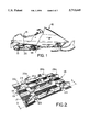
- FIG. 1 is a side perspective view of a snowmobile
- FIG. 2 is an enlarged perspective view of a section of the snowmobile track showing the configuration of the exterior side thereof;
- FIG. 3 is a sectional view taken on the line 3--3 in FIG. 2;
- FIG. 4 is a plan view corresponding to FIG. 3;
- FIG. 5 is a sectional view taken on the line 5--5 in FIG. 4;
- FIG. 6 is a view taken on the line 6--6 in FIG. 4;
- FIG. 7 is a view corresponding to FIG. 4 showing an alternate configuration
- FIG. 8 is a view taken on the line 8--8 in FIG. 7.
- a snowmobile 10 is supported at its forward end on a pair of steerable skies 12 and at its rearward end on a track 14 in the form of an endless belt which passes in a ground-engaging round beneath a slide suspension 25, and at the rear end passes around idler wheels 13.
- the track 14 as is known is fabricated as a moulding of fabric reinforced natural or synthetic rubber, and comprises an endless loop having an exterior side formed with an array 16 of projecting ground-engaging traction elements, and on its interior side has rows of integral projecting drive lugs for engagement by elements of the snowmobile drive train (not shown).
- the lugs 18 are arranged at regular spacing in longitudinally extending rows, and between the outermost rows the belt is formed with a series of rectangular holes 14.
- the belt is flexible in a longitudinal direction, and it is stiffened in the transverse direction by a series of regularly spaced reinforcing rods 22 (FIG.
- the rows of holes 20 divide the track 14 in the transverse direction into a wide central part 14a and narrower outboard parts 14b, although it will be appreciated that the parts 14a and 14b are integrally connected by the reinforcing rods 22 and the surrounding rubber material. Intermediate the location of the successive reinforcing rods 22, the exterior side 17 of the track 14 is recessed and formed with a series of shallow transversely extending corrugations 19.
- the array 16 of ground-engaging ribs on the exterior side of the track is shown as comprising a longitudinally extending row of center ribs 26a on each side of which is a row of angled flank ribs 26b whereas the outboard portions of the track each carries a further row of angled ribs 26c.
- center ribs 26a are of wide angled V-shaped configuration having opposed limbs that are rearwardly angled from the transverse direction by about 20° so that the rear included angle between them is about 140°.
- the flank ribs 26b the outboard ribs 26c likewise angled outwardly to the rear at about 20°, and as shown in FIG. 5, all ribs are substantially in register with one or other of the reinforcing rods 22.
- the ribs 26a, 26b, 26c extend over substantially the entire width of the track except for the region of the holes 24, and this is shown in FIG. 3. However the individual ribs are spaced apart by substantial distances so that no rib occupies more than about 1/5 of the width of the belt.
- the outboard ribs 26c are aligned with a center rib 26a, leaving substantial gaps therebetween as seen in FIG. 4, the flank ribs 26b (registering with the adjacent reinforcing) rod being substantially aligned with these gaps.
- the individual ribs although spaced over substantially the entire outer side 17, are spaced from one another and provide a repeat pattern that corresponds to about twice the distance between adjacent reinforcing rods 22.
- traction ribs are beneficial in terms of tractive effort since successive registering ribs are spaced a sufficient distance apart in the longitudinal direction that there is an adequate amount of snow between them to resist the shearing and compaction action of the ribs. Furthermore, because of the angulation of the ribs, their interaction with the snow ground surface is such as to retain the snow within the area of the track rather than pushing it laterally outwards. This provides good tractive effect and floatation of the track, which is particularly important in light powdered snow.
- the ribs are relatively deep, 11/4 inches as shown, but in some cases depending on the application perhaps as much as 2 inches in height, they do not add excessively to the weight of the track because of the configuration and spacing of the ribs as shown in the drawings and discussed above, i.e. the ribs are relatively small in length and widely spaced.
- the angled arrangement of the ribs provides effective directional control during steering action, and furthermore enhance the stability of the vehicle against side slip when traversing hillsides. Additionally, in braking, the configuration of the ribs is highly effective in providing a large surface for engagement between the track and the snow.
- FIGS. 7 and 8 A modification is shown in FIGS. 7 and 8.
- the track shown herein is essentially the same as the one described in relation to FIGS. 2 to 6 except that it has rows of outboard ribs 26d that extend transversely, rather than at an angle.
- the flat crest of the ribs has a longitudinally extending groove 30 that effects improved traction when running on icy surfaces.
- the ribs are preferably relatively stiff, but embody a degree of resiliency, particularly in the region of the crests thereof.
- the hardness of the rubber adjacent the crests is preferably about 60 to 70 durometer, although it may vary substantially, e.g. from 60 to 80 durometer.
- the hardness of the rubber in the base portion of the ribs and in the remainder of the track is preferably about 80 durometer.
- the total width of a center rib 26a and an adjacent pair of flank ribs 26b in the transverse direction is equal to the spacing between the two rows of sprocket holes 20 so that when viewed in the longitudinal direction the inboard ends of the flank ribs 23 are in register with the outboard ends of the center rib 26a.
- This relationship can be varied as desired.
- the flank ribs 26b could be extended at their inboard ends (or the center rib 26a could be extended at its outboard ends) to create an overlap as viewed in the longitudinal direction.
- these ends of the ribs 26b or 26a could be shortened to create gaps as viewed in the longitudinal direction.
- center rib 26a occupies approximately 44% of the distance between the rows of sprocket holes 20, each flank rib 26b occupying approximately 28% of this distance.
- the limbs of the center rib 26a are angled rearwardly from the transverse direction by about 20°. This angle can be varied widely, and could be as much as 45°.
Abstract
Description
Claims (19)
Priority Applications (1)
| Application Number | Priority Date | Filing Date | Title |
|---|---|---|---|
| US08/393,109 US5713645A (en) | 1995-02-22 | 1995-02-22 | Snowmobile track profile |
Applications Claiming Priority (1)
| Application Number | Priority Date | Filing Date | Title |
|---|---|---|---|
| US08/393,109 US5713645A (en) | 1995-02-22 | 1995-02-22 | Snowmobile track profile |
Publications (1)
| Publication Number | Publication Date |
|---|---|
| US5713645A true US5713645A (en) | 1998-02-03 |
Family
ID=23553310
Family Applications (1)
| Application Number | Title | Priority Date | Filing Date |
|---|---|---|---|
| US08/393,109 Expired - Lifetime US5713645A (en) | 1995-02-22 | 1995-02-22 | Snowmobile track profile |
Country Status (1)
| Country | Link |
|---|---|
| US (1) | US5713645A (en) |
Cited By (42)
| Publication number | Priority date | Publication date | Assignee | Title |
|---|---|---|---|---|
| USD408326S (en) * | 1998-06-15 | 1999-04-20 | Camoplast Inc. | Snowmobile track |
| USD408327S (en) * | 1998-06-15 | 1999-04-20 | Camoplast Inc. | Snowmobile track |
| US6109705A (en) * | 1998-08-07 | 2000-08-29 | Camoplast, Inc. | Snowmobile drive track for traveling on icy and hardened snow surface |
| US6155363A (en) * | 1996-07-30 | 2000-12-05 | Honda Giken Kogyo Kabushiki Kaisha | Crawler belt vehicle |
| WO2001058744A1 (en) * | 2000-02-10 | 2001-08-16 | Denis Morin | A long track mountain snowmobile and a track therefor |
| US6302232B1 (en) | 1998-02-25 | 2001-10-16 | Vernal D. Forbes | Snow vehicle |
| GB2364287A (en) * | 2000-07-04 | 2002-01-23 | Frederick Powada | Flexible track for a tracked vehicle |
| US6422665B1 (en) * | 1999-11-16 | 2002-07-23 | Camoplast, Inc. | Snowmobile track with heat transfer clips |
| US6505896B1 (en) * | 2000-09-01 | 2003-01-14 | Alain Boivin | Track for snow vehicles |
| US6510913B1 (en) | 2000-02-10 | 2003-01-28 | Bombardier Inc. | Long track mountain snowmobile and a track therefor |
| US6575540B2 (en) | 2000-09-18 | 2003-06-10 | Soucy International Inc. | Rubber-band track with various hardness |
| US6609771B2 (en) | 2000-02-10 | 2003-08-26 | Bombardier Inc. | Long track mountain snowmobile and a track therefor |
| US20040026995A1 (en) * | 2002-08-08 | 2004-02-12 | Bombardier Inc. | Vehicle track providing enhanced steerability |
| US6733091B2 (en) * | 2001-02-22 | 2004-05-11 | Soucy International Inc. | Variable pitch track |
| US20040227401A1 (en) * | 2003-02-06 | 2004-11-18 | Denis Courtemanche | Endless track for a track-propelled vehicle |
| US20050168070A1 (en) * | 2004-02-02 | 2005-08-04 | Camoplast Inc. | Endless track with various hardnesses for a recreational vehicle |
| US20050173983A1 (en) * | 2002-05-14 | 2005-08-11 | Naoki Nishimura | Rubber crawler |
| US20060006737A1 (en) * | 2004-07-09 | 2006-01-12 | Camoplast Inc. | Powder snow track for snowmobile |
| US20060081381A1 (en) * | 2004-09-07 | 2006-04-20 | Kassbohrer All Terrain Vehicles, Inc. | Material handling apparatus |
| US20060238027A1 (en) * | 2005-04-26 | 2006-10-26 | Jules Dandurand | Multi-edge traction lug track |
| US20080100133A1 (en) * | 2004-02-17 | 2008-05-01 | Camoplast Inc. | Track Belt Guide Wheels Assembly |
| US20090072618A1 (en) * | 2007-09-13 | 2009-03-19 | Cnh America Llc | Track for Crawler Vehicles |
| US20130049452A1 (en) * | 2010-02-08 | 2013-02-28 | John Menzies Burling | Device to enhance the traction of a tracked vehicle |
| US8776931B2 (en) | 2010-04-20 | 2014-07-15 | Denis Boivin | Track system for an all-wheel drive vehicle |
| US20150097420A1 (en) * | 2006-09-22 | 2015-04-09 | Camoplast Solideal Inc. | Noiseless Elastomeric Tracks for Tracked Vehicles |
| EP2944553A1 (en) * | 2014-05-12 | 2015-11-18 | Hans Hall GmbH | Crawler bar |
| USD768033S1 (en) * | 2015-08-06 | 2016-10-04 | Limited Liability Company “Composit” | Endless elastic track |
| USD768034S1 (en) * | 2015-08-06 | 2016-10-04 | Limited Liability Company “Composit” | Endless elastic track |
| US9505451B2 (en) | 2012-10-11 | 2016-11-29 | Camso Inc. | Endless track for traction of an off-road vehicle such as an all-terrain vehicle (ATV) or a snowmobile |
| US9650091B2 (en) | 2012-05-25 | 2017-05-16 | Joy Mm Delaware, Inc. | Crawler track |
| WO2017111624A1 (en) * | 2015-12-24 | 2017-06-29 | John Menzies Burling | A device to enhance the traction of a tracked vehicle |
| US20190092405A1 (en) * | 2017-09-22 | 2019-03-28 | Camso Inc. | Track for traction of a vehicle |
| US10266216B2 (en) | 2010-04-20 | 2019-04-23 | Denis Boivin | Track system having anti-diving flaps |
| USD869331S1 (en) * | 2018-06-04 | 2019-12-10 | Limited Liability Company “Composit” | Endless track |
| USD869988S1 (en) * | 2018-06-04 | 2019-12-17 | Limited Liability Company “Composit” | Endless track |
| USD869989S1 (en) * | 2018-06-04 | 2019-12-17 | Limited Liability Company “Composit” | Endless track |
| USD881752S1 (en) * | 2018-07-31 | 2020-04-21 | Limited Liability Company “Composit” | Endless track |
| USD881751S1 (en) * | 2018-07-31 | 2020-04-21 | Limited Liability Company “Composit” | Endless track |
| USD887896S1 (en) * | 2018-07-31 | 2020-06-23 | Limited Liability Company “Composit” | Endless track |
| US20210078656A1 (en) * | 2016-01-07 | 2021-03-18 | Camso Inc. | Track system for traction of a vehicle |
| US20210129930A1 (en) * | 2014-02-13 | 2021-05-06 | Camso Inc. | Track for traction of an off-road vehicle such as a snowmobile or an all-terrain vehicle (atv) |
| USD942320S1 (en) | 2017-09-22 | 2022-02-01 | Camso Inc. | Track for traction of a vehicle |
Citations (19)
| Publication number | Priority date | Publication date | Assignee | Title |
|---|---|---|---|---|
| CA39841A (en) * | 1892-08-13 | Albert James Glass | Disk harrow | |
| CA217455A (en) * | 1922-04-04 | Kregresse Adolphe | Flexible caterpillar belt for motor vehicles | |
| US3355225A (en) * | 1966-01-04 | 1967-11-28 | Joy Mfg Co | Grouser configuration for track tread links |
| US3598454A (en) * | 1969-05-26 | 1971-08-10 | Textron Inc | Vehicle drive track stiffener |
| US3619012A (en) * | 1969-10-03 | 1971-11-09 | Rejean Bizier | Snow track |
| CA898862A (en) * | 1972-04-25 | Paul E. Russ, Sr. | Endless track for multi-terrain vehicles | |
| US3704918A (en) * | 1970-01-22 | 1972-12-05 | Bombardier Ltd | Endless track |
| US3762779A (en) * | 1971-03-26 | 1973-10-02 | Gates Rubber Co | Tread element for flexible track |
| US3781067A (en) * | 1972-09-21 | 1973-12-25 | Goodyear Tire & Rubber | Belt track structure |
| US3857617A (en) * | 1973-04-30 | 1974-12-31 | Caterpillar Tractor Co | Split chevron track shoes for track belts |
| US3934944A (en) * | 1974-09-27 | 1976-01-27 | Brunswick Corporation | Ground engaging drive track apparatus for snowmobiles and the like |
| US4217006A (en) * | 1978-08-17 | 1980-08-12 | Arctic Enterprises, Inc. | Drive belt assembly for snowmobiles |
| US4278302A (en) * | 1979-09-04 | 1981-07-14 | Deere & Company | Grouser bar track assembly for snowmobile |
| CA1117570A (en) * | 1978-01-02 | 1982-02-02 | Skega Aktiebolag | Vehicle track |
| USD283206S (en) | 1983-01-26 | 1986-04-01 | Bombardier Inc. | Snowmobile track |
| CA2014852A1 (en) * | 1989-04-18 | 1990-10-18 | Minoru Tokue | Endless track belt for snow mobile |
| US4991911A (en) * | 1988-06-13 | 1991-02-12 | Bombardier Inc. | Track cleat |
| US5005922A (en) * | 1987-05-14 | 1991-04-09 | Edwards, Harper, Mcnew & Company | Double V-shaped endless track drive system |
| CA2100105A1 (en) * | 1992-07-10 | 1994-01-11 | Tateo Muramatsu | Rubber track assembly |
-
1995
- 1995-02-22 US US08/393,109 patent/US5713645A/en not_active Expired - Lifetime
Patent Citations (21)
| Publication number | Priority date | Publication date | Assignee | Title |
|---|---|---|---|---|
| CA39841A (en) * | 1892-08-13 | Albert James Glass | Disk harrow | |
| CA217455A (en) * | 1922-04-04 | Kregresse Adolphe | Flexible caterpillar belt for motor vehicles | |
| CA898862A (en) * | 1972-04-25 | Paul E. Russ, Sr. | Endless track for multi-terrain vehicles | |
| US3355225A (en) * | 1966-01-04 | 1967-11-28 | Joy Mfg Co | Grouser configuration for track tread links |
| US3598454A (en) * | 1969-05-26 | 1971-08-10 | Textron Inc | Vehicle drive track stiffener |
| US3619012A (en) * | 1969-10-03 | 1971-11-09 | Rejean Bizier | Snow track |
| US3704918A (en) * | 1970-01-22 | 1972-12-05 | Bombardier Ltd | Endless track |
| US3762779A (en) * | 1971-03-26 | 1973-10-02 | Gates Rubber Co | Tread element for flexible track |
| CA949624A (en) * | 1971-03-26 | 1974-06-18 | Gates Rubber Company (The) | Tread element for flexible track |
| US3781067A (en) * | 1972-09-21 | 1973-12-25 | Goodyear Tire & Rubber | Belt track structure |
| US3857617A (en) * | 1973-04-30 | 1974-12-31 | Caterpillar Tractor Co | Split chevron track shoes for track belts |
| US3934944A (en) * | 1974-09-27 | 1976-01-27 | Brunswick Corporation | Ground engaging drive track apparatus for snowmobiles and the like |
| CA1117570A (en) * | 1978-01-02 | 1982-02-02 | Skega Aktiebolag | Vehicle track |
| US4217006A (en) * | 1978-08-17 | 1980-08-12 | Arctic Enterprises, Inc. | Drive belt assembly for snowmobiles |
| US4278302A (en) * | 1979-09-04 | 1981-07-14 | Deere & Company | Grouser bar track assembly for snowmobile |
| CA1132169A (en) * | 1979-09-04 | 1982-09-21 | David A. Westimayer | Grouser bar track assembly for snowmobile |
| USD283206S (en) | 1983-01-26 | 1986-04-01 | Bombardier Inc. | Snowmobile track |
| US5005922A (en) * | 1987-05-14 | 1991-04-09 | Edwards, Harper, Mcnew & Company | Double V-shaped endless track drive system |
| US4991911A (en) * | 1988-06-13 | 1991-02-12 | Bombardier Inc. | Track cleat |
| CA2014852A1 (en) * | 1989-04-18 | 1990-10-18 | Minoru Tokue | Endless track belt for snow mobile |
| CA2100105A1 (en) * | 1992-07-10 | 1994-01-11 | Tateo Muramatsu | Rubber track assembly |
Non-Patent Citations (3)
| Title |
|---|
| 1990 1991 Roetin Industries Catalog, pp. 1 and 6. * |
| 1990-1991 Roetin Industries Catalog, pp. 1 and 6. |
| 1995 Roetin Industries Catalog, p. 9. * |
Cited By (64)
| Publication number | Priority date | Publication date | Assignee | Title |
|---|---|---|---|---|
| US6155363A (en) * | 1996-07-30 | 2000-12-05 | Honda Giken Kogyo Kabushiki Kaisha | Crawler belt vehicle |
| US6382338B1 (en) | 1998-02-25 | 2002-05-07 | Vernal D. Forbes | Snow vehicle |
| US6302232B1 (en) | 1998-02-25 | 2001-10-16 | Vernal D. Forbes | Snow vehicle |
| US6626258B1 (en) * | 1998-02-25 | 2003-09-30 | Vernal D. Forbes | Snow vehicle |
| USD408327S (en) * | 1998-06-15 | 1999-04-20 | Camoplast Inc. | Snowmobile track |
| USD408326S (en) * | 1998-06-15 | 1999-04-20 | Camoplast Inc. | Snowmobile track |
| US6109705A (en) * | 1998-08-07 | 2000-08-29 | Camoplast, Inc. | Snowmobile drive track for traveling on icy and hardened snow surface |
| US6431666B2 (en) * | 1999-11-16 | 2002-08-13 | Camoplast Inc. | Snowmobile track with heat transfer clips |
| US6422665B1 (en) * | 1999-11-16 | 2002-07-23 | Camoplast, Inc. | Snowmobile track with heat transfer clips |
| US6973988B2 (en) | 2000-02-10 | 2005-12-13 | Bombardier Recreational Products Inc. | Long track mountain snowmobile and a track therefor |
| US6772852B2 (en) | 2000-02-10 | 2004-08-10 | Bombardier Recreational Products Inc. | Long track mountain snowmobile and a track therefor |
| US6510913B1 (en) | 2000-02-10 | 2003-01-28 | Bombardier Inc. | Long track mountain snowmobile and a track therefor |
| WO2001058744A1 (en) * | 2000-02-10 | 2001-08-16 | Denis Morin | A long track mountain snowmobile and a track therefor |
| US6609771B2 (en) | 2000-02-10 | 2003-08-26 | Bombardier Inc. | Long track mountain snowmobile and a track therefor |
| GB2364287B (en) * | 2000-07-04 | 2003-10-29 | Frederick Powada | Tracks |
| GB2364287A (en) * | 2000-07-04 | 2002-01-23 | Frederick Powada | Flexible track for a tracked vehicle |
| US6505896B1 (en) * | 2000-09-01 | 2003-01-14 | Alain Boivin | Track for snow vehicles |
| US6575540B2 (en) | 2000-09-18 | 2003-06-10 | Soucy International Inc. | Rubber-band track with various hardness |
| US6733091B2 (en) * | 2001-02-22 | 2004-05-11 | Soucy International Inc. | Variable pitch track |
| US20050173983A1 (en) * | 2002-05-14 | 2005-08-11 | Naoki Nishimura | Rubber crawler |
| US7469976B2 (en) * | 2002-05-14 | 2008-12-30 | Bridgestone Corporation | Rubber crawler belt having metal cores and arcuate lugs |
| US20040026995A1 (en) * | 2002-08-08 | 2004-02-12 | Bombardier Inc. | Vehicle track providing enhanced steerability |
| US7018005B2 (en) | 2002-08-08 | 2006-03-28 | Bombardier Recreational Products Inc. | Vehicle track providing enhanced steerability |
| US7048344B2 (en) * | 2003-02-06 | 2006-05-23 | Camoplast, Inc. | Endless track for a track-propelled vehicle |
| US20040227401A1 (en) * | 2003-02-06 | 2004-11-18 | Denis Courtemanche | Endless track for a track-propelled vehicle |
| US20050168070A1 (en) * | 2004-02-02 | 2005-08-04 | Camoplast Inc. | Endless track with various hardnesses for a recreational vehicle |
| US7063396B2 (en) * | 2004-02-02 | 2006-06-20 | Camoplast Inc. | Endless track with various hardnesses for a recreational vehicle |
| US7780247B2 (en) * | 2004-02-17 | 2010-08-24 | Camoplast Inc. | Track belt guide wheels assembly |
| US20080100133A1 (en) * | 2004-02-17 | 2008-05-01 | Camoplast Inc. | Track Belt Guide Wheels Assembly |
| US20060006737A1 (en) * | 2004-07-09 | 2006-01-12 | Camoplast Inc. | Powder snow track for snowmobile |
| US20060081381A1 (en) * | 2004-09-07 | 2006-04-20 | Kassbohrer All Terrain Vehicles, Inc. | Material handling apparatus |
| US7347512B2 (en) * | 2004-09-07 | 2008-03-25 | Camoplast Inc. | Powder snow track for snowmobile |
| US7618102B2 (en) | 2005-04-26 | 2009-11-17 | Camoplast Inc. | Multi-edge traction lug track |
| US20060238027A1 (en) * | 2005-04-26 | 2006-10-26 | Jules Dandurand | Multi-edge traction lug track |
| US20150097420A1 (en) * | 2006-09-22 | 2015-04-09 | Camoplast Solideal Inc. | Noiseless Elastomeric Tracks for Tracked Vehicles |
| US20090072618A1 (en) * | 2007-09-13 | 2009-03-19 | Cnh America Llc | Track for Crawler Vehicles |
| US7854483B2 (en) * | 2007-09-13 | 2010-12-21 | Cnh America Llc | Track for crawler vehicles |
| US20130049452A1 (en) * | 2010-02-08 | 2013-02-28 | John Menzies Burling | Device to enhance the traction of a tracked vehicle |
| US9862436B2 (en) * | 2010-02-08 | 2018-01-09 | John Menzies Burling | Device to enhance the traction of a tracked vehicle |
| US9688323B2 (en) | 2010-04-20 | 2017-06-27 | Denis Boivin | Track system for an all-wheel drive vehicle |
| US10266216B2 (en) | 2010-04-20 | 2019-04-23 | Denis Boivin | Track system having anti-diving flaps |
| US8776931B2 (en) | 2010-04-20 | 2014-07-15 | Denis Boivin | Track system for an all-wheel drive vehicle |
| US9650091B2 (en) | 2012-05-25 | 2017-05-16 | Joy Mm Delaware, Inc. | Crawler track |
| US10526028B2 (en) * | 2012-05-25 | 2020-01-07 | Joy Global Underground Mining Llc | Crawler track |
| US10000247B2 (en) | 2012-05-25 | 2018-06-19 | Joy Global Underground Mining Llc | Crawler track |
| US10179618B2 (en) | 2012-05-25 | 2019-01-15 | Joy Global Underground Mining Llc | Crawler track |
| US9505451B2 (en) | 2012-10-11 | 2016-11-29 | Camso Inc. | Endless track for traction of an off-road vehicle such as an all-terrain vehicle (ATV) or a snowmobile |
| US20210129930A1 (en) * | 2014-02-13 | 2021-05-06 | Camso Inc. | Track for traction of an off-road vehicle such as a snowmobile or an all-terrain vehicle (atv) |
| EP2944553A1 (en) * | 2014-05-12 | 2015-11-18 | Hans Hall GmbH | Crawler bar |
| US9637188B2 (en) | 2014-05-12 | 2017-05-02 | Hans Hall Gmbh | Crawler web |
| USD768033S1 (en) * | 2015-08-06 | 2016-10-04 | Limited Liability Company “Composit” | Endless elastic track |
| USD768034S1 (en) * | 2015-08-06 | 2016-10-04 | Limited Liability Company “Composit” | Endless elastic track |
| US11390341B2 (en) | 2015-12-24 | 2022-07-19 | Jb Innovations Limited | Device to enhance the traction of a tracked vehicle |
| WO2017111624A1 (en) * | 2015-12-24 | 2017-06-29 | John Menzies Burling | A device to enhance the traction of a tracked vehicle |
| US20210078656A1 (en) * | 2016-01-07 | 2021-03-18 | Camso Inc. | Track system for traction of a vehicle |
| US11639209B2 (en) * | 2017-09-22 | 2023-05-02 | Camso Inc. | Track for traction of a vehicle |
| US20190092405A1 (en) * | 2017-09-22 | 2019-03-28 | Camso Inc. | Track for traction of a vehicle |
| USD942320S1 (en) | 2017-09-22 | 2022-02-01 | Camso Inc. | Track for traction of a vehicle |
| USD869989S1 (en) * | 2018-06-04 | 2019-12-17 | Limited Liability Company “Composit” | Endless track |
| USD869988S1 (en) * | 2018-06-04 | 2019-12-17 | Limited Liability Company “Composit” | Endless track |
| USD869331S1 (en) * | 2018-06-04 | 2019-12-10 | Limited Liability Company “Composit” | Endless track |
| USD887896S1 (en) * | 2018-07-31 | 2020-06-23 | Limited Liability Company “Composit” | Endless track |
| USD881751S1 (en) * | 2018-07-31 | 2020-04-21 | Limited Liability Company “Composit” | Endless track |
| USD881752S1 (en) * | 2018-07-31 | 2020-04-21 | Limited Liability Company “Composit” | Endless track |
Similar Documents
| Publication | Publication Date | Title |
|---|---|---|
| US5713645A (en) | Snowmobile track profile | |
| US4332424A (en) | Low disturbance track cleat and ice calk structure for firm or icy snow | |
| US7063396B2 (en) | Endless track with various hardnesses for a recreational vehicle | |
| US4218101A (en) | Low disturbance track cleat and ice calk structure for firm or icy snow | |
| US2899242A (en) | Bombardier | |
| US6030057A (en) | Tractor endless tread | |
| US3498684A (en) | Traction belt | |
| US6065818A (en) | Rubber track belt with improved traction and durability | |
| CA2405908C (en) | Track for all terrain vehicle | |
| US3897839A (en) | Ski snow deflector | |
| US3619012A (en) | Snow track | |
| US3390924A (en) | Grouser shoe | |
| CA1039777A (en) | Ground engaging drive track apparatus for snowmobiles and the like | |
| US3285677A (en) | Reinforced endless rubber belt | |
| US3883191A (en) | Endless track | |
| US2707658A (en) | Endless track | |
| US3762779A (en) | Tread element for flexible track | |
| US3711164A (en) | Snowmobile slide rail suspension | |
| US3582155A (en) | Tread for motor-driven vehicle | |
| US4116496A (en) | Internal snow deflector for snowmobile track | |
| US3917360A (en) | Snowmobile track | |
| US20190092405A1 (en) | Track for traction of a vehicle | |
| US3712689A (en) | Track for snowmobile or the like | |
| US5415470A (en) | Clip for snowmobile track and snowmobile track provided with the same | |
| CA2143262A1 (en) | Snowmobile track profile |
Legal Events
| Date | Code | Title | Description |
|---|---|---|---|
| AS | Assignment |
Owner name: BOMBARDIER INC., CANADA Free format text: ASSIGNMENT OF ASSIGNORS INTEREST;ASSIGNOR:BEDARD, SERGE A.;REEL/FRAME:007522/0329 Effective date: 19950215 |
|
| AS | Assignment |
Owner name: BOMBARDIER INC., CANADA Free format text: ASSIGNMENT OF ASSIGNORS INTEREST;ASSIGNOR:THOMPSON, MARK B.;REEL/FRAME:007731/0809 Effective date: 19951016 |
|
| STCF | Information on status: patent grant |
Free format text: PATENTED CASE |
|
| FPAY | Fee payment |
Year of fee payment: 4 |
|
| AS | Assignment |
Owner name: BOMBARDIER RECREATIONAL PRODUCTS INC., CANADA Free format text: ASSIGNMENT OF ASSIGNORS INTEREST;ASSIGNOR:BOMBARDIER INC.;REEL/FRAME:014294/0453 Effective date: 20031218 |
|
| FPAY | Fee payment |
Year of fee payment: 8 |
|
| FEPP | Fee payment procedure |
Free format text: PAYER NUMBER DE-ASSIGNED (ORIGINAL EVENT CODE: RMPN); ENTITY STATUS OF PATENT OWNER: LARGE ENTITY |
|
| FEPP | Fee payment procedure |
Free format text: PAYOR NUMBER ASSIGNED (ORIGINAL EVENT CODE: ASPN); ENTITY STATUS OF PATENT OWNER: LARGE ENTITY Free format text: PAYER NUMBER DE-ASSIGNED (ORIGINAL EVENT CODE: RMPN); ENTITY STATUS OF PATENT OWNER: LARGE ENTITY |
|
| FEPP | Fee payment procedure |
Free format text: PAYOR NUMBER ASSIGNED (ORIGINAL EVENT CODE: ASPN); ENTITY STATUS OF PATENT OWNER: LARGE ENTITY |
|
| REMI | Maintenance fee reminder mailed | ||
| FPAY | Fee payment |
Year of fee payment: 12 |
|
| SULP | Surcharge for late payment |
Year of fee payment: 11 |
|
| AS | Assignment |
Owner name: BANK OF MONTREAL, CANADA Free format text: SECURITY AGREEMENT;ASSIGNOR:BOMBARDIER RECREATIONAL PRODUCTS INC.;REEL/FRAME:031159/0540 Effective date: 20130822 |
|
| AS | Assignment |
Owner name: BANK OF MONTREAL, CANADA Free format text: SECURITY AGREEMENT;ASSIGNOR:BOMBARDIER RECREATIONAL PRODUCTS INC.;REEL/FRAME:031156/0144 Effective date: 20130822 |