US5702470A - Prosthetic wrist implant and related method of implantation - Google Patents
Prosthetic wrist implant and related method of implantation Download PDFInfo
- Publication number
- US5702470A US5702470A US08/605,525 US60552596A US5702470A US 5702470 A US5702470 A US 5702470A US 60552596 A US60552596 A US 60552596A US 5702470 A US5702470 A US 5702470A
- Authority
- US
- United States
- Prior art keywords
- implant
- carpal
- bone
- radius
- radial
- Prior art date
- Legal status (The legal status is an assumption and is not a legal conclusion. Google has not performed a legal analysis and makes no representation as to the accuracy of the status listed.)
- Expired - Lifetime
Links
Images


Classifications
-
- A—HUMAN NECESSITIES
- A61—MEDICAL OR VETERINARY SCIENCE; HYGIENE
- A61B—DIAGNOSIS; SURGERY; IDENTIFICATION
- A61B17/00—Surgical instruments, devices or methods, e.g. tourniquets
- A61B17/16—Bone cutting, breaking or removal means other than saws, e.g. Osteoclasts; Drills or chisels for bones; Trepans
- A61B17/1662—Bone cutting, breaking or removal means other than saws, e.g. Osteoclasts; Drills or chisels for bones; Trepans for particular parts of the body
- A61B17/1686—Bone cutting, breaking or removal means other than saws, e.g. Osteoclasts; Drills or chisels for bones; Trepans for particular parts of the body for the hand or wrist
-
- A—HUMAN NECESSITIES
- A61—MEDICAL OR VETERINARY SCIENCE; HYGIENE
- A61B—DIAGNOSIS; SURGERY; IDENTIFICATION
- A61B17/00—Surgical instruments, devices or methods, e.g. tourniquets
- A61B17/14—Surgical saws ; Accessories therefor
- A61B17/15—Guides therefor
-
- A—HUMAN NECESSITIES
- A61—MEDICAL OR VETERINARY SCIENCE; HYGIENE
- A61B—DIAGNOSIS; SURGERY; IDENTIFICATION
- A61B17/00—Surgical instruments, devices or methods, e.g. tourniquets
- A61B17/16—Bone cutting, breaking or removal means other than saws, e.g. Osteoclasts; Drills or chisels for bones; Trepans
- A61B17/1659—Surgical rasps, files, planes, or scrapers
-
- A—HUMAN NECESSITIES
- A61—MEDICAL OR VETERINARY SCIENCE; HYGIENE
- A61F—FILTERS IMPLANTABLE INTO BLOOD VESSELS; PROSTHESES; DEVICES PROVIDING PATENCY TO, OR PREVENTING COLLAPSING OF, TUBULAR STRUCTURES OF THE BODY, e.g. STENTS; ORTHOPAEDIC, NURSING OR CONTRACEPTIVE DEVICES; FOMENTATION; TREATMENT OR PROTECTION OF EYES OR EARS; BANDAGES, DRESSINGS OR ABSORBENT PADS; FIRST-AID KITS
- A61F2/00—Filters implantable into blood vessels; Prostheses, i.e. artificial substitutes or replacements for parts of the body; Appliances for connecting them with the body; Devices providing patency to, or preventing collapsing of, tubular structures of the body, e.g. stents
- A61F2/02—Prostheses implantable into the body
- A61F2/30—Joints
- A61F2/42—Joints for wrists or ankles; for hands, e.g. fingers; for feet, e.g. toes
- A61F2/4261—Joints for wrists or ankles; for hands, e.g. fingers; for feet, e.g. toes for wrists
-
- A—HUMAN NECESSITIES
- A61—MEDICAL OR VETERINARY SCIENCE; HYGIENE
- A61B—DIAGNOSIS; SURGERY; IDENTIFICATION
- A61B17/00—Surgical instruments, devices or methods, e.g. tourniquets
- A61B2017/0046—Surgical instruments, devices or methods, e.g. tourniquets with a releasable handle; with handle and operating part separable
-
- A—HUMAN NECESSITIES
- A61—MEDICAL OR VETERINARY SCIENCE; HYGIENE
- A61B—DIAGNOSIS; SURGERY; IDENTIFICATION
- A61B17/00—Surgical instruments, devices or methods, e.g. tourniquets
- A61B2017/00477—Coupling
-
- A—HUMAN NECESSITIES
- A61—MEDICAL OR VETERINARY SCIENCE; HYGIENE
- A61F—FILTERS IMPLANTABLE INTO BLOOD VESSELS; PROSTHESES; DEVICES PROVIDING PATENCY TO, OR PREVENTING COLLAPSING OF, TUBULAR STRUCTURES OF THE BODY, e.g. STENTS; ORTHOPAEDIC, NURSING OR CONTRACEPTIVE DEVICES; FOMENTATION; TREATMENT OR PROTECTION OF EYES OR EARS; BANDAGES, DRESSINGS OR ABSORBENT PADS; FIRST-AID KITS
- A61F2/00—Filters implantable into blood vessels; Prostheses, i.e. artificial substitutes or replacements for parts of the body; Appliances for connecting them with the body; Devices providing patency to, or preventing collapsing of, tubular structures of the body, e.g. stents
- A61F2/02—Prostheses implantable into the body
- A61F2/30—Joints
- A61F2/46—Special tools or methods for implanting or extracting artificial joints, accessories, bone grafts or substitutes, or particular adaptations therefor
- A61F2/4603—Special tools or methods for implanting or extracting artificial joints, accessories, bone grafts or substitutes, or particular adaptations therefor for insertion or extraction of endoprosthetic joints or of accessories thereof
- A61F2/4606—Special tools or methods for implanting or extracting artificial joints, accessories, bone grafts or substitutes, or particular adaptations therefor for insertion or extraction of endoprosthetic joints or of accessories thereof of wrists or ankles; of hands, e.g. fingers; of feet, e.g. toes
-
- A—HUMAN NECESSITIES
- A61—MEDICAL OR VETERINARY SCIENCE; HYGIENE
- A61F—FILTERS IMPLANTABLE INTO BLOOD VESSELS; PROSTHESES; DEVICES PROVIDING PATENCY TO, OR PREVENTING COLLAPSING OF, TUBULAR STRUCTURES OF THE BODY, e.g. STENTS; ORTHOPAEDIC, NURSING OR CONTRACEPTIVE DEVICES; FOMENTATION; TREATMENT OR PROTECTION OF EYES OR EARS; BANDAGES, DRESSINGS OR ABSORBENT PADS; FIRST-AID KITS
- A61F2/00—Filters implantable into blood vessels; Prostheses, i.e. artificial substitutes or replacements for parts of the body; Appliances for connecting them with the body; Devices providing patency to, or preventing collapsing of, tubular structures of the body, e.g. stents
- A61F2/02—Prostheses implantable into the body
- A61F2/30—Joints
- A61F2/46—Special tools or methods for implanting or extracting artificial joints, accessories, bone grafts or substitutes, or particular adaptations therefor
- A61F2/4684—Trial or dummy prostheses
-
- A—HUMAN NECESSITIES
- A61—MEDICAL OR VETERINARY SCIENCE; HYGIENE
- A61F—FILTERS IMPLANTABLE INTO BLOOD VESSELS; PROSTHESES; DEVICES PROVIDING PATENCY TO, OR PREVENTING COLLAPSING OF, TUBULAR STRUCTURES OF THE BODY, e.g. STENTS; ORTHOPAEDIC, NURSING OR CONTRACEPTIVE DEVICES; FOMENTATION; TREATMENT OR PROTECTION OF EYES OR EARS; BANDAGES, DRESSINGS OR ABSORBENT PADS; FIRST-AID KITS
- A61F2/00—Filters implantable into blood vessels; Prostheses, i.e. artificial substitutes or replacements for parts of the body; Appliances for connecting them with the body; Devices providing patency to, or preventing collapsing of, tubular structures of the body, e.g. stents
- A61F2/02—Prostheses implantable into the body
- A61F2/30—Joints
- A61F2002/30001—Additional features of subject-matter classified in A61F2/28, A61F2/30 and subgroups thereof
- A61F2002/30108—Shapes
- A61F2002/30199—Three-dimensional shapes
- A61F2002/30252—Three-dimensional shapes quadric-shaped
- A61F2002/30253—Three-dimensional shapes quadric-shaped ellipsoidal or ovoid
-
- A—HUMAN NECESSITIES
- A61—MEDICAL OR VETERINARY SCIENCE; HYGIENE
- A61F—FILTERS IMPLANTABLE INTO BLOOD VESSELS; PROSTHESES; DEVICES PROVIDING PATENCY TO, OR PREVENTING COLLAPSING OF, TUBULAR STRUCTURES OF THE BODY, e.g. STENTS; ORTHOPAEDIC, NURSING OR CONTRACEPTIVE DEVICES; FOMENTATION; TREATMENT OR PROTECTION OF EYES OR EARS; BANDAGES, DRESSINGS OR ABSORBENT PADS; FIRST-AID KITS
- A61F2/00—Filters implantable into blood vessels; Prostheses, i.e. artificial substitutes or replacements for parts of the body; Appliances for connecting them with the body; Devices providing patency to, or preventing collapsing of, tubular structures of the body, e.g. stents
- A61F2/02—Prostheses implantable into the body
- A61F2/30—Joints
- A61F2002/30001—Additional features of subject-matter classified in A61F2/28, A61F2/30 and subgroups thereof
- A61F2002/30667—Features concerning an interaction with the environment or a particular use of the prosthesis
- A61F2002/30708—Means for distinguishing between left-sided and right-sided devices, Sets comprising both left-sided and right-sided prosthetic parts
-
- A—HUMAN NECESSITIES
- A61—MEDICAL OR VETERINARY SCIENCE; HYGIENE
- A61F—FILTERS IMPLANTABLE INTO BLOOD VESSELS; PROSTHESES; DEVICES PROVIDING PATENCY TO, OR PREVENTING COLLAPSING OF, TUBULAR STRUCTURES OF THE BODY, e.g. STENTS; ORTHOPAEDIC, NURSING OR CONTRACEPTIVE DEVICES; FOMENTATION; TREATMENT OR PROTECTION OF EYES OR EARS; BANDAGES, DRESSINGS OR ABSORBENT PADS; FIRST-AID KITS
- A61F2/00—Filters implantable into blood vessels; Prostheses, i.e. artificial substitutes or replacements for parts of the body; Appliances for connecting them with the body; Devices providing patency to, or preventing collapsing of, tubular structures of the body, e.g. stents
- A61F2/02—Prostheses implantable into the body
- A61F2/30—Joints
- A61F2/30767—Special external or bone-contacting surface, e.g. coating for improving bone ingrowth
- A61F2/30771—Special external or bone-contacting surface, e.g. coating for improving bone ingrowth applied in original prostheses, e.g. holes or grooves
- A61F2002/3082—Grooves
-
- A—HUMAN NECESSITIES
- A61—MEDICAL OR VETERINARY SCIENCE; HYGIENE
- A61F—FILTERS IMPLANTABLE INTO BLOOD VESSELS; PROSTHESES; DEVICES PROVIDING PATENCY TO, OR PREVENTING COLLAPSING OF, TUBULAR STRUCTURES OF THE BODY, e.g. STENTS; ORTHOPAEDIC, NURSING OR CONTRACEPTIVE DEVICES; FOMENTATION; TREATMENT OR PROTECTION OF EYES OR EARS; BANDAGES, DRESSINGS OR ABSORBENT PADS; FIRST-AID KITS
- A61F2/00—Filters implantable into blood vessels; Prostheses, i.e. artificial substitutes or replacements for parts of the body; Appliances for connecting them with the body; Devices providing patency to, or preventing collapsing of, tubular structures of the body, e.g. stents
- A61F2/02—Prostheses implantable into the body
- A61F2/30—Joints
- A61F2/30767—Special external or bone-contacting surface, e.g. coating for improving bone ingrowth
- A61F2/30771—Special external or bone-contacting surface, e.g. coating for improving bone ingrowth applied in original prostheses, e.g. holes or grooves
- A61F2002/30878—Special external or bone-contacting surface, e.g. coating for improving bone ingrowth applied in original prostheses, e.g. holes or grooves with non-sharp protrusions, for instance contacting the bone for anchoring, e.g. keels, pegs, pins, posts, shanks, stems, struts
- A61F2002/30884—Fins or wings, e.g. longitudinal wings for preventing rotation within the bone cavity
-
- A—HUMAN NECESSITIES
- A61—MEDICAL OR VETERINARY SCIENCE; HYGIENE
- A61F—FILTERS IMPLANTABLE INTO BLOOD VESSELS; PROSTHESES; DEVICES PROVIDING PATENCY TO, OR PREVENTING COLLAPSING OF, TUBULAR STRUCTURES OF THE BODY, e.g. STENTS; ORTHOPAEDIC, NURSING OR CONTRACEPTIVE DEVICES; FOMENTATION; TREATMENT OR PROTECTION OF EYES OR EARS; BANDAGES, DRESSINGS OR ABSORBENT PADS; FIRST-AID KITS
- A61F2/00—Filters implantable into blood vessels; Prostheses, i.e. artificial substitutes or replacements for parts of the body; Appliances for connecting them with the body; Devices providing patency to, or preventing collapsing of, tubular structures of the body, e.g. stents
- A61F2/02—Prostheses implantable into the body
- A61F2/30—Joints
- A61F2/42—Joints for wrists or ankles; for hands, e.g. fingers; for feet, e.g. toes
- A61F2/4261—Joints for wrists or ankles; for hands, e.g. fingers; for feet, e.g. toes for wrists
- A61F2002/4264—Joints for wrists or ankles; for hands, e.g. fingers; for feet, e.g. toes for wrists for radio-carpal joints
-
- A—HUMAN NECESSITIES
- A61—MEDICAL OR VETERINARY SCIENCE; HYGIENE
- A61F—FILTERS IMPLANTABLE INTO BLOOD VESSELS; PROSTHESES; DEVICES PROVIDING PATENCY TO, OR PREVENTING COLLAPSING OF, TUBULAR STRUCTURES OF THE BODY, e.g. STENTS; ORTHOPAEDIC, NURSING OR CONTRACEPTIVE DEVICES; FOMENTATION; TREATMENT OR PROTECTION OF EYES OR EARS; BANDAGES, DRESSINGS OR ABSORBENT PADS; FIRST-AID KITS
- A61F2/00—Filters implantable into blood vessels; Prostheses, i.e. artificial substitutes or replacements for parts of the body; Appliances for connecting them with the body; Devices providing patency to, or preventing collapsing of, tubular structures of the body, e.g. stents
- A61F2/02—Prostheses implantable into the body
- A61F2/30—Joints
- A61F2/46—Special tools or methods for implanting or extracting artificial joints, accessories, bone grafts or substitutes, or particular adaptations therefor
- A61F2002/4631—Special tools or methods for implanting or extracting artificial joints, accessories, bone grafts or substitutes, or particular adaptations therefor the prosthesis being specially adapted for being cemented
-
- A—HUMAN NECESSITIES
- A61—MEDICAL OR VETERINARY SCIENCE; HYGIENE
- A61F—FILTERS IMPLANTABLE INTO BLOOD VESSELS; PROSTHESES; DEVICES PROVIDING PATENCY TO, OR PREVENTING COLLAPSING OF, TUBULAR STRUCTURES OF THE BODY, e.g. STENTS; ORTHOPAEDIC, NURSING OR CONTRACEPTIVE DEVICES; FOMENTATION; TREATMENT OR PROTECTION OF EYES OR EARS; BANDAGES, DRESSINGS OR ABSORBENT PADS; FIRST-AID KITS
- A61F2230/00—Geometry of prostheses classified in groups A61F2/00 - A61F2/26 or A61F2/82 or A61F9/00 or A61F11/00 or subgroups thereof
- A61F2230/0063—Three-dimensional shapes
- A61F2230/0073—Quadric-shaped
- A61F2230/0076—Quadric-shaped ellipsoidal or ovoid
-
- A—HUMAN NECESSITIES
- A61—MEDICAL OR VETERINARY SCIENCE; HYGIENE
- A61F—FILTERS IMPLANTABLE INTO BLOOD VESSELS; PROSTHESES; DEVICES PROVIDING PATENCY TO, OR PREVENTING COLLAPSING OF, TUBULAR STRUCTURES OF THE BODY, e.g. STENTS; ORTHOPAEDIC, NURSING OR CONTRACEPTIVE DEVICES; FOMENTATION; TREATMENT OR PROTECTION OF EYES OR EARS; BANDAGES, DRESSINGS OR ABSORBENT PADS; FIRST-AID KITS
- A61F2250/00—Special features of prostheses classified in groups A61F2/00 - A61F2/26 or A61F2/82 or A61F9/00 or A61F11/00 or subgroups thereof
- A61F2250/0058—Additional features; Implant or prostheses properties not otherwise provided for
- A61F2250/0084—Means for distinguishing between left-sided and right-sided devices; Sets comprising both left-sided and right-sided prosthetic parts
-
- A—HUMAN NECESSITIES
- A61—MEDICAL OR VETERINARY SCIENCE; HYGIENE
- A61F—FILTERS IMPLANTABLE INTO BLOOD VESSELS; PROSTHESES; DEVICES PROVIDING PATENCY TO, OR PREVENTING COLLAPSING OF, TUBULAR STRUCTURES OF THE BODY, e.g. STENTS; ORTHOPAEDIC, NURSING OR CONTRACEPTIVE DEVICES; FOMENTATION; TREATMENT OR PROTECTION OF EYES OR EARS; BANDAGES, DRESSINGS OR ABSORBENT PADS; FIRST-AID KITS
- A61F2310/00—Prostheses classified in A61F2/28 or A61F2/30 - A61F2/44 being constructed from or coated with a particular material
- A61F2310/00005—The prosthesis being constructed from a particular material
- A61F2310/00011—Metals or alloys
- A61F2310/00023—Titanium or titanium-based alloys, e.g. Ti-Ni alloys
Definitions
- This invention relates to prosthetic implants and more particularly to a prosthetic wrist implant with a geometry that closely matches that of the natural wrist and which minimizes bone resection.
- Existing prosthetic wrist implants have a number of drawbacks. Because of their size needed to achieve the necessary strength, wrist implants have typically required excessive amounts of bone to be resected. For example, in these implants relatively large and lengthy implant stems were inserted into the radius and carpal bones. This significantly weakened the bones making them more susceptible to post operative fracture. Furthermore, once fracture occurs, because of the significant loss of bone due to resection, their may not be enough bone left to permit a satisfactory fusion procedure. This may leave patient without even fusion as an avenue of treatment.
- an improved prosthetic wrist implant which overcomes some or all of the above-discussed problems.
- a wrist implant which has a geometry which matches that of a natural wrist and which affords the patient a natural range of motion, natural flexion and natural extension of the hand.
- a prosthetic wrist implant which is small enough to minimize the bone resection required.
- an improved method for attaching a prosthetic wrist implant which provides a stable and strong attachment to the bone without requiring excessive loss of bone through resection or drilling.
- a method of implanting a prosthetic wrist implant which minimizes bone resection and which affords the patient the above-described desirable features.
- the prosthetic wrist implant of the present invention combines a number of positive design features to provide an implant having an optimal range of motion with acceptable flexion and extension of the hand. It does this by incorporating a unique geometry that matches that of the natural wrist. For example, an inclined articular surface of the radial component of the implant mimics the articular surface of the radius.
- the prosthetic wrist implant of the present invention incorporates an improved technique for attaching to the bone which utilizes a combination of posts and screws. This, coupled with the small size of the implant, minimizes the bone resection and bone loss. This results in a stronger attachment as well as stronger bone structure post operatively.
- the prosthetic wrist implant comprises a radial implant having an elongated concave articular front surface and a back surface having a first flat face and a second flat face tilted at an angle with respect to the first flat face.
- the radial implant also has a first post member projecting from the second flat face into a cavity in the radial bone.
- the wrist also includes a carpal bone implant including a planar member having a front face and a generally flat rear face, and a second post member projecting from the rear face into a cavity into the carpal bone complex.
- the wrist implant also includes an articulating member having a flat bottom surface fastened to the front face of the planar member and an elongated convex surface slidingly engaging the concave articulating surface of the radial implant to permit articulation between the radial and carpal bone complex along the articular surfaces.
- the carpal bone implant planar member has two openings therein and a pair of screws inserted through the two planar member openings into the carpal bone complex.
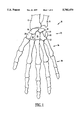
- FIG. 1 is a drawing of the bones of the left hand dorsal surface.
- FIGS. 2A-B are side and front elevational views respectively of the components of the prosthetic wrist implant in accordance with a preferred embodiment of the present invention.
- FIGS. 3A-3E are various views of the radial implant component of the present invention.
- FIGS. 4A-4D are various views of the carpal implant component of the present invention.
- FIGS. 5A-5C are various views of the carpal bearing component of the present invention.
- FIG. 6 is a side elevational view of a radial body templet for performing radial resection in accordance with a preferred embodiment of the method of the present invention.
- FIGS. 7A-7E are various views of a radius cutting guide and broach used for the left radius in accordance with the method of the present invention.
- FIGS. 8A-8E are various views of a radius cutting guide and broach used for the right radius in accordance with the method of the present invention.
- FIGS. 9A-9C are various views of a radial pusher beating used for installing the radial component of the present invention.
- FIG. 10 is a side elevational view of a radial pusher handle used with the radial pusher bearing in FIGS. 9A-9C.
- FIGS. 11A-11F show x-ray templets used for three sizes of the present invention.
- FIG. 12 is a phantom view of the left hand showing the surgical incision utilized in accordance with the method of the present invention.
- FIG. 13 is a perspective view of radius and ulnar bones showing ulnar resection in accordance with the present invention.
- FIG. 14 is a perspective view of the bones of the left hand, the resectioned ulnar and the distal radius illustrating the resection method of the present invention.
- FIG. 15 is a perspective view of the bones of the left hand illustrating the carpal resection in accordance with the method of the present invention.
- FIG. 16 is a perspective view of the bones of the left hand illustrating the technique of drilling into the center of the capitate/mediocarpal complex in accordance with the method of the present invention.
- FIGS. 17A-B illustrate the technique of preparing the radius using a broach in accordance with the method of the present invention.
- FIG. 18A and 18C are illustrations of the incorrect way to prepare the radius in accordance with the method of the present invention.
- FIG. 18B is an illustration of the correct way in which to prepare the radius in accordance with the method of the present invention.
- FIG. 19 is a perspective view of the bones of the left hand with a trial wrist implant in place showing the range of motion of the wrists.
- FIG. 20 is a perspective view of the bones of the left hand illustrating the fixation of the carpal component of the prosthetic wrist implant of the present invention.
- FIGS. 21A-B are perspective views of the radius and ulnar bones illustrating the technique of fixation of the radial component of the prosthetic wrist implant of the present invention.
- FIG. 22 is a pre-operative x-ray of a patient suffering from radio-carpal arthritis.
- FIG. 23 is a x-ray of the patient's wrist shown in FIG. 22 32 months post-operative.
- FIG. 24 is a perspective view of a prosthetic wrist implant in accordance with an alternative embodiment of the present invention.
- FIG. 25 is a top view of the prosthetic wrist implant of FIG. 24.
- FIG. 26 is a rear view of the prosthetic wrist implant in accordance with the embodiment of FIG. 24.
- FIG. 27 is a front view of the prosthetic wrist implant shown in FIG. 24.
- FIG. 28 is a bottom view of the prosthetic wrist implant of FIG. 24.
- FIG. 29 is a right side elevational view of the prosthetic wrist implant of FIG. 24.
- FIG. 30 is a left side elevational view of the prosthetic wrist implant of FIG. 24.
- the present invention is for a prosthetic wrist implant and a method for performing the operation of implanting the prosthetic wrist implant.
- the prosthetic wrist implant of the present invention minimizes bone resection and allows natural articulation of the hand. It has a geometry which matches that of a natural wrist to afford a natural range of motion to the patient.
- An inclined articular surface of the radial component of the implant mimics the articulate surface of the radius. It's small size and method of attachment minimizes bone resection. It utilizes screws for attachment of the carpal component which provides a stable and strong attachment with minimal drilling.
- FIG. 1 there is shown the bones of the left hand viewing the dorsal surface and including the radius and ulnar.
- FIG. 1 shows the bones of the wrist 10 which includes the radius 12, the ulna 14, the scaphoid 16, the lunate 18, the triquetrum 20, the hamate 22, the capatate 24, and the lesser 26 and greater 28 trapezoid bones.
- pisiform bone 30 Also shown is pisiform bone 30.
- These eight bones 16-30 make up the carpus 32 of the hand. Additional bones which will not be discussed in detail include the metacarpus bones 34 and the phalanges bones 36.
- the scaphoid 16 and lunate 18 bones articulate with the radius 12 to provide motion of the wrists.
- wrists disorders such as radio-carpal arthritis
- patients may experience discomfort, pain and difficulty in moving the wrist.
- Prior surgical treatment of this condition involves fusion which, as discussed previously, will prevent articulation of the scaphoid and lunate bones with the radius.
- the patient may have their pain alleviated, but is left without motion of the wrists. This severely restricts the patient's use of their wrist.
- prosthetic wrist implants have been developed to provide an artificial articulating surface for the wrists.
- previous implants have suffered from a number of drawbacks such as those discussed above including limited range of motion and excessive bone resection which significantly weakens the bones in question and subjects them to a greater likelihood of fracture.
- an improved prosthetic wrist implant which minimizes the amount of bone which is resected and which provides the patient with a very natural range of motion and flexion. It does this by its unique geometry, small size and unique method of attachment.
- FIGS. 2A and B the prosthetic wrist implant of the present invention 38 is shown.
- a side view of the wrist implant 38 shows the three components including a radial implant 40, a bearing component 42 and a carpal implant 44.
- FIG. 2B shows these three components in a side view.
- the prosthetic wrist implant 38 incorporates a bearing guide 46 which is tilted with respect to the axis of the radius into which a radius post 48 is inserted.
- the carpal implant component 44 includes a flat base member 49 and a post member 50 which is inserted into the carpus 32.
- the bearing 42 is mounted affixedly to the flat carpal base member 49 and provides a self-lubricating surface which is articulated against the bearing guide 46.
- FIG. 3A shows the bearing guide 46 which preferably includes a concaved bearing surface 52. As shown in FIG. 3B, this curved surface 52, in the preferred embodiment, has a radius of 0.914 inches.
- the bearing guide 46 is preferably disposed at approximately a 20 degree angle also has a back face 54 which abuts against the surface of the radius bone 12 as described in more detail below.
- a second fiat surface 56 of the bearing guide 46 is disposed at a 20 degree angle with the bearing guide back surface 54.
- the radial post 48 is attached to the bearing guide back surface 54 and includes a post surface 58 which is preferably at approximately a 10.25 degree angle with respect to the axis of the radius 60.
- the post 48 also is preferably generally tapered from the back bearing guide surface 54 at surfaces 62, 64 and 66 as shown in FIG. 3B.
- the radial post 48 preferably tapers down from its attachment from the shape shown at 68, where it is attached to the face 54, down to a rounded end portion 70.
- FIG. 3D is similar to FIG. 3b with additional dimensions and angles of the preferred embodiment shown.
- FIG. 3D is similar to FIG. 3b with additional dimensions and angles of the preferred embodiment shown.
- 3E is a side view of the radial implant 40 showing that the bearing articulating surface 52 along the side axis has a radius of approximately 0.319 inches.
- radial implant 40 is made of titanium such as Ti-6AI-4V(F136).
- Ti-6AI-4V(F136) titanium
- FIGS. 4A-4D the carpal implant component 44 of the present invention is shown.
- the carpal implant 44 includes a front face 70 which is preferably attached to the carpal bearing 42 by means of locking tabs 72 and 74.
- Locking tabs 72 and 74 also preferably have tapered holes 76 and 78 through which attachment screws (described below) are inserted into the carpal bones.
- locking tabs 72 and 74 preferably include a raised head portion 80 and 82 and slots 84 and 86.
- the raised head portions 80 and 82 and slots 84 and 86 are configured to engage with slots in the carpal bearing 42 as described in more detail below.
- Tab 88 is a slightly raised tab which also engages with a slot in the carpal bearing as described below.
- Carpal post 50 protrudes perpendicularly from the back face 90 of the carpal implant 44. Also shown in FIG. 4A opening 92 which is threaded and may be used to attach an instrument to facilitate pushing the carpal implant 44 into the carpal bone.
- FIG. 4C shows the location of the opening 92 and the post 50 of the preferred embodiment when viewed from the back surface 90 of the carpal implant.
- the carpal post 50 is shown including a series of grooves 94 which serve to secure the post 50 into the carpal bone once it is implanted such as with cement.
- post 50 is preferably inserted into the capitate bone 24 as described in more detail below.
- the screws inserted into holes 76 and 78 are screwed into the hamate 22 and trapezoid bones as described in more detail below.
- the carpal implant 42 is likewise preferably made of the same material as the radial implant 40, such as titanium.
- the carpal bearing 42 as seen in FIG. 5A in end view has a convex articulating surface 96 which has a radius of approximately 0.314 inches. Also a small slot 98 is preferably on one edge of the carpal beating 42, and a tapered recess 100 is located on the carpal bearing bottom face 102. As shown in FIGS. 5B and 5C, the carpal bearing bottom surface 102 also preferably includes slots 104, having a lip portion 106. When installing the carpal bearing 42 on to the carpal implant 44, the slots 104 engage with the raised tabs 72, 74 as the carpal bearing is slid sideways over the carpal implant front surface 70.
- Carpal bearing 42 in the preferred embodiment is made ultra high molecular weight polyethylene (UHMWPe). However, it will be appreciated that other self-lubricating plastic materials may also be employed. In addition, other materials such as metal may also be used in some situations.
- UHMWPe ultra high molecular weight polyethylene
- FIG. 6 there is shown a radial body templet which is used to determine the correct angle at which to resect the radial bone.
- the axis of the radius is shown at line 110
- the resection cut of the radius will be made along slot 112. This cut will be at a 20 degree angle with the line 114, which is normal to the radius bone axis 110.
- Radial body templet 108 is preferably made of 1/8 stainless steel.
- FIGS. 7A-E there is shown various views of a radius cutting guide for use on a left radius bone in a manner described below.
- a broach 118 used for resecting the radius bone interior as described in more detail below.
- FIGS. 8A-8D show a radius cutting guide 120 which is the same as radius cutting guide 116 except that it is used on the fight radius.
- marks 122 on the radius cutting guide indicate three positions depending on the size of the patient and corresponding size of implants, designated small, medium and large (SML). This guide would thereby control the depth of the cutting of broach 118 show in FIG. 8E.
- FIGS. 9A-9C show various views of a radial pusher bearing 124 which will be used in conjunction with radial pusher handle 126, shown in FIG. 10.
- radial pusher handle 126 is threaded into opening 128 in the radial pusher bearing 126 and is used to push the carpal implant post 50 into the capitate bone.
- FIGS. 11A-F illustrate x-ray templets used in conjunction with the prosthetic wrist implant 38 to ensure proper sizing of the implant prior to the surgical operation of as discussed in more detail below. Small, medium and large sizes of the implants are shown in two views in the x-ray templet.
- FIGS. 12-21 Prior to performing the prosthetic wrist implant surgical procedure in accordance with the present invention, the patient is placed under general anesthesia. Alternatively auxiliary block anesthesia may be used. A tourniquet is used to obtain a bloodless field. Prior to the procedure, x-ray templets as shown in FIGS. 11A-11F are used to determine the correct size (for example small, medium and large) of the wrist prosthesis.
- a longitudinal dorsal incision 128 is made over the wrist along the line of the third metacarpal.
- Subcutaneous tissue and skin are elevated sharply from the extensor tendons and retracted medially and laterally using three zero silk retraction sutures.
- the extensor retinaculum is opened up in a step cut fashion so that one half can be utilized to close the joint capsule.
- the extensor retinaculum is opened over the fourth compartment and raised medially and laterally.
- a dorsal synovectomy is carried out and the wrist extensors are checked for structural integrity.
- the capsule over the distal ulna is opened longitudinally. As shown in FIG. 13, the distal one cementer of the ulna 14 is osteotimized and removed. A synovectomy of the ulnar compartment is then performed.
- the joint capsule is detached from the distal radius and left attached distally. Dissection is carried out radially. The brachioradialis is elevated and the tendons of the first dorsal compartment muscles from the styloid process are elevated subperiosteally. The branch of the posterior intraosseous nerve is resected and the accompanying vessels cauterized. A haze retractor is inserted to protect the sutures.
- the distal end of the radius is identified by palpation as the wrist is passively flexed and extended. Wrist joint evectomy is done. The wrist is flexed and the haze retractors on either side of the radius expose the end.
- the radial cutting jig is aligned along the longitudinal axis of the radius on the dorsal aspect of the radius as shown in FIG. 14. The dorsal lip and the radial articular surface is osteotomized and removed.
- the radial cutting jig weight is aligned along the longitudinal axis of the dorsal aspect of the radius. Using an oscillating saw, the line of osteotomy is marked. The jig is removed, and using the saw, the osteotomy is completed. The line of osteotomy is about 20 degrees to the longitudinal axis of the radius. Only the dorsal lip and the articular surface are removed. If necessary, additional bone is removed after the initial trial and reduction. Traction is applied to the hand by the assistant and the hand is held along the line of the forearm.
- the line 130 of the osteotomy for the carpal bones passes through the proximal end of the capitate 24.
- the plane of the osteotomy is perpendicular to the axis of the capitate mediocarpal complex. If the carpal is subluxed, traction should be applied to the hand to bring the carpal bones from under the radius.
- the capitate must be positively identified prior to resection. For example, the wrist may be flexed to about 80 degrees. Part of the scaphoid and the triquetrum are left intact, along with the distal carpal bones.
- An intercarpal fusion is carried out by removing the cartilage from the articular surfaces of the capitate, triquetrum, hamate and the scaphoid using a burr or curette. All loose fragments of bone are removed from the joint. If there are any large defects in the volar capsule, they are then closed with absorbable sutures.
- a hole in the center of the capitate-metacarpal complex is made using a 3.2 millimeter drill bit.
- the drill bit starts at the center of the capitate and proceeds into the third metacarpal.
- the drill needs to angled to about ten degrees dorsally to accomplish the correct alignment.
- a probe is introduced into this hole and using an image intensifier, the position of the probe is checked. When viewed in the image intensifier, the probe must be intraosseous in both the AP and lateral planes.
- the hole is then enlarged to accept the stem 50 of the carpal component with a 3.5 millimeter drill bit.
- FIGS. 17A and B To prepare the radius as shown in FIGS. 17A and B, the surgeon sits at the end of the hand table in order to have a end-on view of the distal radius 12
- the medullary canal of the radius is reamed with an appropriate size broach such as broach 118.
- the broach should be inserted at a valgus angle shown in FIG. 17B and not at the varus angle shown in FIG. 17A.
- the second radial cutting block is aligned over the broach and the radius is cut to match the contour of the radial component.
- FIGS. 18A-C indicate malrotation of rasp as compared to correct positioning. That is, FIGS. 18A and C indicate wrong positioning and FIG. 18b indicates the correct positioning.
- a trial reduction is then performed.
- the stem of a trial carpal component 50 is introduced into the opening in the capitate bone.
- a drill hole is made through the radial opening in the carpal plate capturing the scaphoid and the trapezoid bones using a 2.5 millimeter drill bit.
- a 20 millimeter long and 4.5 millimeter or diameter self-taping screw is then inserted to obtain the temporary fixation.
- a trial radial component is then inserted into the medullary canal of the radius.
- Trial plastic carpal bearing 124 is slid over the carpal plate and the joint is reduced as shown in FIG. 19. If the joint is too tight, additional bone is removed from the radius until good dorsiflexion, palmarflexion, radial and ulnar deviation is achieved. The wrist should easily stay in neutral position or in the balance state.
- Bone cement is introduced into the central peg hole in the capitate metacarpal complex.
- this bone cement may comprise methylemethacrylate.
- the stem of the carpal implant 50 is introduced into this hole and tapped all of the way in as shown in FIG. 20 utilizing the trial bearing 124 and the radial pusher handle 126. It is important to keep the implant flush with the bone margins. Care must be taken to remove excess cement, especially from the intracarpal region.
- the ulnar side of the plate is then drilled with a 2.5 millimeter bit. Two 4.5 millimeter screws are then inserted through the peripheral holes in the carpal plate 48.
- the radial screw is longer and could cross the carpal space mediocarpal joint. Since the carpal mediocarpal joint of the fourth and fifth metacarpals are mobile, care should be taken to avoid crossing these joints. (Unless it is necessary for better purchase.)
- the screws help hold the fragment of the triquetrum and the scaphoid in place and add strength to the carpal fixation.
- the bone screws 132, 134 shown in FIG. 23 secure the hamate 22 and trapezoid 26, 28 bones respectively.
- These bones screws may comprise, for example, conventional 4.5 millimeter diameter bone screws which are between 20 and 40 millimeters in length depending on the size of the implant and patient. Cancellous bone graphs obtained from the radius and resected carpal bones are packed into the defects between the carpal bones to obtain a uniform bony fusion.
- a bone plug is inserted into the medullary canal of the radius to act as a cement restricter.
- the canal is cleaned with pulse lavage and dried.
- Bone cement is mixed and injected into the canal using a syringe as shown in FIG. 21A.
- the true radial component 40 is then introduced into the medullary canal as shown in FIG. 21B. It is important to remove all excess cement from the immediate area. Care is taken to place the prosthesis in a valgus position. A varus angle of the component will result in a post-operative ulnar deviation deformity of the hand.
- the carpal bearing 42 is then slid over the carpal plate and locked into place using finger pressure or gently taps with an impactor over the carpal implant plate 48. The components are then reduced and the joint is tested for range of motion and stability.
- Wound closure is accomplished by first closing the ulnar joint capsule tightly, thereby stabilizing the distal ulnar.
- the ECU tendon is brought dorsally to obtain additional stability.
- the capsule of the radial carpal joint is reattached to the distal end of the radius. If the capsule is deficient, one-half of the extensor retinaculum is used to cover the defects. Meticulous closure of the capsule is mandatory to ensure stability in the post operative.
- the hand is then immobilized in bulky dressing with the wrist in a neutral position for about two to three days. Post operative management will involve removing the sutures after ten days.
- the wrists should be kept immobilized in a short arm cast for four weeks. After four weeks the east is removed and the range of motion exercises begun.
- FIG. 22 a pre-operative x-ray of a patient suffering from radio-carpal arthritis is shown.
- FIG. 23 shows the same patient 32 months post-operatively now asymptomatic and with good functional range of motion.
- the implant includes a radial implant component 138, a carpal component 140 and a bearing component 142.
- the radial component 138 and bearing component 142 are similar to radial component 40 and 42 respectively shown in FIGS. 2A and B.
- the carpal component 140 does not have a carpal post 50. Instead, opening 144 is used to accept a screw which is inserted into the capitate bone 24 in place of the carpal post 50.
Landscapes
- Health & Medical Sciences (AREA)
- Life Sciences & Earth Sciences (AREA)
- Surgery (AREA)
- Veterinary Medicine (AREA)
- Animal Behavior & Ethology (AREA)
- Orthopedic Medicine & Surgery (AREA)
- Oral & Maxillofacial Surgery (AREA)
- Engineering & Computer Science (AREA)
- Biomedical Technology (AREA)
- Heart & Thoracic Surgery (AREA)
- Public Health (AREA)
- General Health & Medical Sciences (AREA)
- Nuclear Medicine, Radiotherapy & Molecular Imaging (AREA)
- Molecular Biology (AREA)
- Medical Informatics (AREA)
- Dentistry (AREA)
- Cardiology (AREA)
- Transplantation (AREA)
- Vascular Medicine (AREA)
- Prostheses (AREA)
Abstract
Description
Claims (9)
Priority Applications (4)
| Application Number | Priority Date | Filing Date | Title |
|---|---|---|---|
| US08/605,525 US5702470A (en) | 1996-02-23 | 1996-02-23 | Prosthetic wrist implant and related method of implantation |
| US08/806,265 US6059832A (en) | 1996-02-23 | 1997-02-24 | Prosthetic wrist implants, instruments, and related methods of implantation |
| PCT/US1997/002740 WO1997030665A2 (en) | 1996-02-23 | 1997-02-24 | Prosthetic wrist implants, instruments, and related methods of implantation |
| AU21343/97A AU2134397A (en) | 1996-02-23 | 1997-02-24 | Prosthetic wrist implants, instruments, and related methods of implantation |
Applications Claiming Priority (1)
| Application Number | Priority Date | Filing Date | Title |
|---|---|---|---|
| US08/605,525 US5702470A (en) | 1996-02-23 | 1996-02-23 | Prosthetic wrist implant and related method of implantation |
Related Child Applications (1)
| Application Number | Title | Priority Date | Filing Date |
|---|---|---|---|
| US08/806,265 Continuation-In-Part US6059832A (en) | 1996-02-23 | 1997-02-24 | Prosthetic wrist implants, instruments, and related methods of implantation |
Publications (1)
| Publication Number | Publication Date |
|---|---|
| US5702470A true US5702470A (en) | 1997-12-30 |
Family
ID=24424033
Family Applications (2)
| Application Number | Title | Priority Date | Filing Date |
|---|---|---|---|
| US08/605,525 Expired - Lifetime US5702470A (en) | 1996-02-23 | 1996-02-23 | Prosthetic wrist implant and related method of implantation |
| US08/806,265 Expired - Lifetime US6059832A (en) | 1996-02-23 | 1997-02-24 | Prosthetic wrist implants, instruments, and related methods of implantation |
Family Applications After (1)
| Application Number | Title | Priority Date | Filing Date |
|---|---|---|---|
| US08/806,265 Expired - Lifetime US6059832A (en) | 1996-02-23 | 1997-02-24 | Prosthetic wrist implants, instruments, and related methods of implantation |
Country Status (3)
| Country | Link |
|---|---|
| US (2) | US5702470A (en) |
| AU (1) | AU2134397A (en) |
| WO (1) | WO1997030665A2 (en) |
Cited By (61)
| Publication number | Priority date | Publication date | Assignee | Title |
|---|---|---|---|---|
| US5906210A (en) * | 1997-06-12 | 1999-05-25 | Stuckenbrock Medizintechnik Gmbh | Surgical procedure for restoration of stability and painfree rotation of the distal radio-ulnar joint |
| US6379386B1 (en) * | 1997-09-09 | 2002-04-30 | Stryker Technologies Corporation | Anatomic glenoid shoulder prosthesis together with methods and tools for implanting same |
| US20030009170A1 (en) * | 2001-07-09 | 2003-01-09 | Alain Tornier | Ancillary tool for fitting an ulnar component and/or a radial component of an elbow prosthesis |
| US20030187511A1 (en) * | 2002-03-26 | 2003-10-02 | Ball Robert J. | Wrist prosthesis |
| US20030216813A1 (en) * | 2002-03-29 | 2003-11-20 | Ball Robert J. | Distal component for wrist prosthesis |
| WO2004026169A2 (en) * | 2002-09-18 | 2004-04-01 | Kinetikos Medical Incorporated | Wrist implant apparatus and method |
| US6746486B1 (en) * | 2002-10-24 | 2004-06-08 | Biomet, Inc. | Method and apparatus for total wrist angled back carpal plate |
| US20040138756A1 (en) * | 2003-01-09 | 2004-07-15 | Nathan Reeder | Method for preparing radial and carpal bones for a wrist prosthesis |
| US20050049710A1 (en) * | 2003-08-28 | 2005-03-03 | O'driscoll Shawn W. | Prosthesis for partial replacement of an articulating surface on bone |
| US20050085921A1 (en) * | 2003-07-22 | 2005-04-21 | Amitava Gupta | Prosthetic wrist implant |
| US20050137709A1 (en) * | 2003-12-22 | 2005-06-23 | Conrad Klotz | Modular radial component for a total wrist arthroplasty |
| WO2005086939A2 (en) | 2004-03-11 | 2005-09-22 | Acumed Llc | Systems for bone replacement |
| US20060036330A1 (en) * | 2002-10-24 | 2006-02-16 | Biomet Manufacturing Corp. | Method and apparatus for wrist arthroplasty |
| US20060142866A1 (en) * | 2004-08-23 | 2006-06-29 | Mark Baratz | Radial head implant apparatuses and methods |
| US20070055381A1 (en) * | 2002-10-24 | 2007-03-08 | Berelsman Brian K | Method and apparatus for wrist arthroplasty |
| US20070225820A1 (en) * | 2003-12-23 | 2007-09-27 | Ascension Orthopedics, Inc. | Total wrist prosthesis |
| US20080027558A1 (en) * | 2002-10-24 | 2008-01-31 | Biomet Manufacturing Corp. | Method And Apparatus For Wrist Arthroplasty |
| US20080154369A1 (en) * | 2006-11-07 | 2008-06-26 | Barr George A | Medical implants |
| US20080195217A1 (en) * | 2005-12-22 | 2008-08-14 | Luis Roman Scheker | Lateral elbow prosthesis - proximal radioulnar joint |
| WO2008097781A1 (en) * | 2007-02-02 | 2008-08-14 | Ascension Orthopedics, Inc. | Wrist preparation system and method |
| US20090204224A1 (en) * | 2002-10-24 | 2009-08-13 | Biomet Manufacturing Corp. | Method And Apparatus For Wrist Arthroplasty |
| US20090254189A1 (en) * | 2005-10-13 | 2009-10-08 | Aptis Medical, Llc | Wrist prosthesis |
| US20090254190A1 (en) * | 2008-01-07 | 2009-10-08 | Jamy Gannoe | System and method for trapezium bone replacement |
| US20090312839A1 (en) * | 2005-12-22 | 2009-12-17 | Aptis Medical, Llc | Lateral elbow prosthesis - proximal radioulnar joint |
| US20090319050A1 (en) * | 2002-10-24 | 2009-12-24 | Biomet Manufacturing Corp. | Method and Apparatus for Wrist Arthroplasty |
| US20100010636A1 (en) * | 2002-10-24 | 2010-01-14 | Biomet Manufacturing Corp. | Method and Apparatus for Wrist Arthroplasty |
| US20100087879A1 (en) * | 2002-10-24 | 2010-04-08 | Biomet Manufacturing Corp. | Method and Apparatus for Wrist Arthroplasty |
| US20100161064A1 (en) * | 2006-11-07 | 2010-06-24 | Kellar Franz W | Prosthetic joint |
| US20100262250A1 (en) * | 2006-11-07 | 2010-10-14 | Kellar Franz W | Prosthetic ball-and-socket joint |
| US7875082B2 (en) * | 2008-05-09 | 2011-01-25 | Remi Sciences, Inc. | Ulnar head prosthesis system |
| US20110077744A1 (en) * | 2009-09-30 | 2011-03-31 | Imbriglia Joseph E | Resurfacing Implant for the Wrist and Method of Implantation Thereof |
| US20110087333A1 (en) * | 2006-11-07 | 2011-04-14 | Kellar Franz W | Prosthetic knee joint |
| US20110166671A1 (en) * | 2006-11-07 | 2011-07-07 | Kellar Franz W | Prosthetic joint |
| US20110166667A1 (en) * | 2006-11-07 | 2011-07-07 | Kellar Franz W | Prosthetic ball-and-socket joint |
| US8052755B2 (en) * | 2008-05-09 | 2011-11-08 | Remi Sciences, Inc. | Ulnar head prosthesis system |
| CN101708139B (en) * | 2009-05-31 | 2012-08-08 | 天津市威曼生物材料有限公司 | Ball-and-socket type wrist joint prosthesis device |
| US8303589B2 (en) | 2008-06-24 | 2012-11-06 | Extremity Medical Llc | Fixation system, an intramedullary fixation assembly and method of use |
| US8308812B2 (en) | 2006-11-07 | 2012-11-13 | Biomedflex, Llc | Prosthetic joint assembly and joint member therefor |
| US8313487B2 (en) | 2008-06-24 | 2012-11-20 | Extremity Medical Llc | Fixation system, an intramedullary fixation assembly and method of use |
| US8328806B2 (en) | 2008-06-24 | 2012-12-11 | Extremity Medical, Llc | Fixation system, an intramedullary fixation assembly and method of use |
| US8343199B2 (en) | 2008-06-24 | 2013-01-01 | Extremity Medical, Llc | Intramedullary fixation screw, a fixation system, and method of fixation of the subtalar joint |
| EP2559407A2 (en) | 2011-08-19 | 2013-02-20 | Integra LifeSciences Corporation | Wrist implants and methods |
| US8512413B2 (en) | 2006-11-07 | 2013-08-20 | Biomedflex, Llc | Prosthetic knee joint |
| US20130325130A1 (en) * | 2012-05-31 | 2013-12-05 | Howmedica Osteonics Corp. | Lateral entry insert for cup trial |
| CN103445888A (en) * | 2013-09-11 | 2013-12-18 | 徐永清 | Externally clamping fixed high-functionality artificial wrist joint prosthesis device |
| US20140358243A1 (en) * | 2013-05-30 | 2014-12-04 | Trimed, Inc. | Method of reconstructing a patient's wrist |
| US8906102B2 (en) | 2012-05-31 | 2014-12-09 | Howmedica Osteonics Corp. | Lateral entry insert for cup trial |
| US8940055B2 (en) | 2002-10-24 | 2015-01-27 | Biomet Manufacturing, Llc | Method and apparatus for wrist arthroplasty |
| US9005307B2 (en) | 2006-11-07 | 2015-04-14 | Biomedflex, Llc | Prosthetic ball-and-socket joint |
| US9017329B2 (en) | 2008-06-24 | 2015-04-28 | Extremity Medical, Llc | Intramedullary fixation assembly and method of use |
| US9044282B2 (en) | 2008-06-24 | 2015-06-02 | Extremity Medical Llc | Intraosseous intramedullary fixation assembly and method of use |
| US9078758B2 (en) | 2011-05-12 | 2015-07-14 | Howmedica Osteonics Corp. | Wrist implant for carpal hemiarthroplasty |
| US9155626B2 (en) | 2012-09-10 | 2015-10-13 | Acumed Llc | Radial head prosthesis with floating articular member |
| US9289220B2 (en) | 2008-06-24 | 2016-03-22 | Extremity Medical Llc | Intramedullary fixation assembly and method of use |
| US9421106B2 (en) | 2011-12-07 | 2016-08-23 | Howmedica Osteonics Corp. | Reverse shoulder baseplate with alignment guide for glenosphere |
| US9549826B2 (en) | 2004-12-01 | 2017-01-24 | Mayo Foundation For Medical Research And Education | Sigmoid notch implant |
| WO2017120645A1 (en) * | 2016-01-15 | 2017-07-20 | Field Orthopaedics Pty Ltd | A joint stabilisation method and apparatus |
| TWI593380B (en) * | 2015-03-23 | 2017-08-01 | 台灣微創醫療器材股份有限公司 | Injection device for biological tissue repair |
| US9763792B2 (en) | 2015-10-01 | 2017-09-19 | Acumed Llc | Radial head prosthesis with rotate-to-lock interface |
| US10390972B2 (en) | 2016-01-15 | 2019-08-27 | Howmedica Osteonics Corp. | Humeral trial adaptor |
| US10940023B2 (en) | 2016-12-15 | 2021-03-09 | Stryker European Holdings I, Llc | Bone plate trial |
Families Citing this family (17)
| Publication number | Priority date | Publication date | Assignee | Title |
|---|---|---|---|---|
| DE19820015C2 (en) * | 1998-05-06 | 2000-09-07 | Schaefer Micomed Gmbh | Prosthetic wrist |
| SE516039C3 (en) * | 2000-03-23 | 2002-01-09 | Philippe Kopylov Ab | Sound substitute for the distal radioulnar joint |
| DE20120241U1 (en) * | 2001-12-14 | 2003-04-24 | Keramed Medizintechnik Gmbh | Endoprosthesis |
| DE10237016A1 (en) * | 2002-08-13 | 2004-02-26 | Moje-Keramik-Implantate | Modular wrist implant, comprising convex elliptical part joined with cylindrical shaft to concave elliptical socket |
| US6932823B2 (en) * | 2003-06-24 | 2005-08-23 | Zimmer Technology, Inc. | Detachable support arm for surgical navigation system reference array |
| US20050215888A1 (en) * | 2004-03-05 | 2005-09-29 | Grimm James E | Universal support arm and tracking array |
| US20060052691A1 (en) * | 2004-03-05 | 2006-03-09 | Hall Maleata Y | Adjustable navigated tracking element mount |
| US20060161059A1 (en) * | 2005-01-20 | 2006-07-20 | Zimmer Technology, Inc. | Variable geometry reference array |
| US7819924B2 (en) * | 2005-11-14 | 2010-10-26 | Ascension Orthopedics, Inc. | Distal radioulnar joint prosthesis |
| US20080051909A1 (en) | 2006-08-22 | 2008-02-28 | The Hospital For Special Surgery | Wrist implants |
| WO2009076758A1 (en) * | 2007-12-18 | 2009-06-25 | The Royal Institution For The Advancement Of Learning/Mcgill University | Orthopaedic implants |
| US20100168799A1 (en) * | 2008-12-29 | 2010-07-01 | Schumer Evan D | Ulnar osteotomy plate including increased compression |
| US9084688B2 (en) | 2009-05-19 | 2015-07-21 | DePuy Synthes Products, Inc. | Dynamic trial implants |
| US10098749B2 (en) * | 2015-07-31 | 2018-10-16 | Ryan A. Jefferis | Proximal interphalangeal joint prothesis |
| US10413418B2 (en) * | 2016-03-24 | 2019-09-17 | Skeletal Dynamics, Llc | Total wrist prosthesis and related methods |
| EP4111989A1 (en) * | 2019-05-14 | 2023-01-04 | LOCI Orthopaedics Limited | A set of tools for installing an implant |
| USD952147S1 (en) | 2020-12-31 | 2022-05-17 | Orthocision Inc. | Joint finder |
Citations (12)
| Publication number | Priority date | Publication date | Assignee | Title |
|---|---|---|---|---|
| US3875594A (en) * | 1973-08-27 | 1975-04-08 | Dow Corning | Surgically implantable prosthetic joint having load distributing flexible hinge |
| US4106128A (en) * | 1976-12-06 | 1978-08-15 | Greenwald A Seth | Endoprosthetic bone joint |
| US4158893A (en) * | 1976-10-12 | 1979-06-26 | Swanson Alfred B | Protective sleeve for implantable prosthesis and method of protecting the prosthesis |
| US4164793A (en) * | 1978-04-26 | 1979-08-21 | Swanson Alfred B | Lunate implant |
| US4178640A (en) * | 1978-02-23 | 1979-12-18 | Boswick John A Jr | Wrist prosthesis |
| US4198713A (en) * | 1976-10-12 | 1980-04-22 | Swanson Alfred B | Protective member for implantable prosthesis and method of protecting the prosthesis |
| EP0034192A1 (en) * | 1980-02-14 | 1981-08-26 | Howmedica International, Inc. | A wrist prosthesis |
| US4784661A (en) * | 1985-11-22 | 1988-11-15 | Robert Beckenbaugh | Total wrist prosthesis |
| WO1992000709A1 (en) * | 1990-07-07 | 1992-01-23 | University Of Strathclyde | Joint prosthesis |
| US5314485A (en) * | 1991-09-12 | 1994-05-24 | Etablissements Tornier | Total prosthesis of the wrist |
| US5326364A (en) * | 1992-12-16 | 1994-07-05 | Wright Medical Technology, Inc. | Trapezial implant |
| US5507821A (en) * | 1993-01-21 | 1996-04-16 | Sulzer Medizinaltechnik Ag | Artificial wrist joint |
Family Cites Families (1)
| Publication number | Priority date | Publication date | Assignee | Title |
|---|---|---|---|---|
| CA2078840C (en) * | 1991-09-24 | 1998-08-11 | Alan J. Yeadon | Wrist prothesis |
-
1996
- 1996-02-23 US US08/605,525 patent/US5702470A/en not_active Expired - Lifetime
-
1997
- 1997-02-24 US US08/806,265 patent/US6059832A/en not_active Expired - Lifetime
- 1997-02-24 WO PCT/US1997/002740 patent/WO1997030665A2/en active Application Filing
- 1997-02-24 AU AU21343/97A patent/AU2134397A/en not_active Abandoned
Patent Citations (12)
| Publication number | Priority date | Publication date | Assignee | Title |
|---|---|---|---|---|
| US3875594A (en) * | 1973-08-27 | 1975-04-08 | Dow Corning | Surgically implantable prosthetic joint having load distributing flexible hinge |
| US4158893A (en) * | 1976-10-12 | 1979-06-26 | Swanson Alfred B | Protective sleeve for implantable prosthesis and method of protecting the prosthesis |
| US4198713A (en) * | 1976-10-12 | 1980-04-22 | Swanson Alfred B | Protective member for implantable prosthesis and method of protecting the prosthesis |
| US4106128A (en) * | 1976-12-06 | 1978-08-15 | Greenwald A Seth | Endoprosthetic bone joint |
| US4178640A (en) * | 1978-02-23 | 1979-12-18 | Boswick John A Jr | Wrist prosthesis |
| US4164793A (en) * | 1978-04-26 | 1979-08-21 | Swanson Alfred B | Lunate implant |
| EP0034192A1 (en) * | 1980-02-14 | 1981-08-26 | Howmedica International, Inc. | A wrist prosthesis |
| US4784661A (en) * | 1985-11-22 | 1988-11-15 | Robert Beckenbaugh | Total wrist prosthesis |
| WO1992000709A1 (en) * | 1990-07-07 | 1992-01-23 | University Of Strathclyde | Joint prosthesis |
| US5314485A (en) * | 1991-09-12 | 1994-05-24 | Etablissements Tornier | Total prosthesis of the wrist |
| US5326364A (en) * | 1992-12-16 | 1994-07-05 | Wright Medical Technology, Inc. | Trapezial implant |
| US5507821A (en) * | 1993-01-21 | 1996-04-16 | Sulzer Medizinaltechnik Ag | Artificial wrist joint |
Non-Patent Citations (7)
| Title |
|---|
| CFV Wrist System, Biomet, Inc., Form No. Y BMT 152/013190. * |
| CFV Wrist System, Biomet, Inc., Form No. Y-BMT-152/013190. |
| Silastic HP 100 Swanson Finger Joint Implant and Dow Corning Wright Swanson Finger Joint Grommet II, Dow Corning Wright Catalog. * |
| The Journal of Bone and Joint Surgery, vol. 69 A, No. 7, Sep. 1987, Jayasanker Menon, M.D., Total Wrist Replacement Using the Modified Volz Prothesis . * |
| The Journal of Bone and Joint Surgery, vol. 69-A, No. 7, Sep. 1987, Jayasanker Menon, M.D., "Total Wrist Replacement Using the Modified Volz Prothesis". |
| The Journal of Hand Surgery, vol. 20A No. 1, Hans Christoph Meuli, MD, et al., Jan. 1995, "Uncemented Total Wrist Arthroplasty", pp. 115-121, 802. |
| The Journal of Hand Surgery, vol. 20A No. 1, Hans Christoph Meuli, MD, et al., Jan. 1995, Uncemented Total Wrist Arthroplasty , pp. 115 121, 802. * |
Cited By (123)
| Publication number | Priority date | Publication date | Assignee | Title |
|---|---|---|---|---|
| US5906210A (en) * | 1997-06-12 | 1999-05-25 | Stuckenbrock Medizintechnik Gmbh | Surgical procedure for restoration of stability and painfree rotation of the distal radio-ulnar joint |
| US6379386B1 (en) * | 1997-09-09 | 2002-04-30 | Stryker Technologies Corporation | Anatomic glenoid shoulder prosthesis together with methods and tools for implanting same |
| US6673115B2 (en) | 1997-09-09 | 2004-01-06 | Stryker Technologies Corporation | Anatomic glenoid shoulder prosthesis together with methods and tools for implanting same |
| US20030009170A1 (en) * | 2001-07-09 | 2003-01-09 | Alain Tornier | Ancillary tool for fitting an ulnar component and/or a radial component of an elbow prosthesis |
| US7922728B2 (en) * | 2001-07-09 | 2011-04-12 | Tornier Sas | Ancillary tool for fitting an ulnar component and/or a radial component of an elbow prosthesis |
| US20030187511A1 (en) * | 2002-03-26 | 2003-10-02 | Ball Robert J. | Wrist prosthesis |
| US20030216813A1 (en) * | 2002-03-29 | 2003-11-20 | Ball Robert J. | Distal component for wrist prosthesis |
| US6890358B2 (en) | 2002-03-29 | 2005-05-10 | Depuy Products, Inc. | Distal component for wrist prosthesis |
| WO2004026169A2 (en) * | 2002-09-18 | 2004-04-01 | Kinetikos Medical Incorporated | Wrist implant apparatus and method |
| US7531003B2 (en) | 2002-09-18 | 2009-05-12 | Integra Lifesciences Corporation | Wrist implant apparatus and method |
| US20040117025A1 (en) * | 2002-09-18 | 2004-06-17 | Reindel Eric S. | Wrist implant apparatus and method |
| EP1581143A4 (en) * | 2002-09-18 | 2006-07-05 | Kinetikos Medical Inc | Wrist implant apparatus and method |
| WO2004026169A3 (en) * | 2002-09-18 | 2005-11-17 | Kinetikos Medical Inc | Wrist implant apparatus and method |
| EP1581143A2 (en) * | 2002-09-18 | 2005-10-05 | Kinetikos Medical Incorporated | Wrist implant apparatus and method |
| US8821581B2 (en) | 2002-10-24 | 2014-09-02 | Biomet Manufacturing, Llc | Method and apparatus for wrist arthroplasty |
| US20050004675A1 (en) * | 2002-10-24 | 2005-01-06 | Shultz Jason M. | Method and apparatus for wrist arthroplasty |
| US8052756B2 (en) | 2002-10-24 | 2011-11-08 | Biomet Manufacturing Corp. | Method and apparatus for wrist arthroplasty |
| US8066777B2 (en) | 2002-10-24 | 2011-11-29 | Biomet Manufacturing Corp. | Method and apparatus for wrist arthroplasty |
| US8105389B2 (en) | 2002-10-24 | 2012-01-31 | Biomet Manufacturing Corp. | Method and apparatus for wrist arthroplasty |
| US6746486B1 (en) * | 2002-10-24 | 2004-06-08 | Biomet, Inc. | Method and apparatus for total wrist angled back carpal plate |
| US8105390B2 (en) | 2002-10-24 | 2012-01-31 | Biomet Manufacturing Corp. | Method and apparatus for wrist arthroplasty |
| US8105388B2 (en) | 2002-10-24 | 2012-01-31 | Biomet Manufacturing Corp. | Method and apparatus for wrist arthroplasty |
| US8372154B2 (en) * | 2002-10-24 | 2013-02-12 | Biomet Manufacturing Corp. | Method and apparatus for wrist arthroplasty |
| US20060036330A1 (en) * | 2002-10-24 | 2006-02-16 | Biomet Manufacturing Corp. | Method and apparatus for wrist arthroplasty |
| US7766970B2 (en) | 2002-10-24 | 2010-08-03 | Biomet Manufacturing Corp. | Method and apparatus for wrist arthroplasty |
| US8940055B2 (en) | 2002-10-24 | 2015-01-27 | Biomet Manufacturing, Llc | Method and apparatus for wrist arthroplasty |
| US8551180B2 (en) | 2002-10-24 | 2013-10-08 | Biomet Manufacturing, Llc | Method and apparatus for wrist arthroplasty |
| US20070055381A1 (en) * | 2002-10-24 | 2007-03-08 | Berelsman Brian K | Method and apparatus for wrist arthroplasty |
| US20100087879A1 (en) * | 2002-10-24 | 2010-04-08 | Biomet Manufacturing Corp. | Method and Apparatus for Wrist Arthroplasty |
| US20080027558A1 (en) * | 2002-10-24 | 2008-01-31 | Biomet Manufacturing Corp. | Method And Apparatus For Wrist Arthroplasty |
| US10085842B2 (en) | 2002-10-24 | 2018-10-02 | Biomet Manufacturing, Llc | Method and apparatus for wrist arthroplasty |
| US20090204224A1 (en) * | 2002-10-24 | 2009-08-13 | Biomet Manufacturing Corp. | Method And Apparatus For Wrist Arthroplasty |
| US20100010636A1 (en) * | 2002-10-24 | 2010-01-14 | Biomet Manufacturing Corp. | Method and Apparatus for Wrist Arthroplasty |
| US20090319050A1 (en) * | 2002-10-24 | 2009-12-24 | Biomet Manufacturing Corp. | Method and Apparatus for Wrist Arthroplasty |
| US20040138756A1 (en) * | 2003-01-09 | 2004-07-15 | Nathan Reeder | Method for preparing radial and carpal bones for a wrist prosthesis |
| US6827741B2 (en) * | 2003-01-09 | 2004-12-07 | Zimmer Technology, Inc. | Method for preparing radial and carpal bones for a wrist prosthesis |
| US8758445B2 (en) * | 2003-07-22 | 2014-06-24 | Avanta Orthopaedics, Llc | Prosthetic wrist implant |
| US9233004B2 (en) | 2003-07-22 | 2016-01-12 | Howmedica Osteonics Corp. | Prosthetic wrist implant |
| US20050085921A1 (en) * | 2003-07-22 | 2005-04-21 | Amitava Gupta | Prosthetic wrist implant |
| US7625408B2 (en) * | 2003-07-22 | 2009-12-01 | Avanta Orthopaedics, Llc | Prosthetic wrist implant |
| US7628819B2 (en) | 2003-07-22 | 2009-12-08 | Avanta Orthopaedics, Llc | Prosthetic wrist implant |
| US8118876B2 (en) * | 2003-07-22 | 2012-02-21 | Avanta Orthopaedics, Llc | Prosthetic wrist implant |
| US20100076568A1 (en) * | 2003-07-22 | 2010-03-25 | Avanta Orthopaedics, Llc | Prosthetic wrist implant |
| US20120150308A1 (en) * | 2003-07-22 | 2012-06-14 | Avanta Orthopaedics, Llc | Prosthetic wrist implant |
| US20060004462A1 (en) * | 2003-07-22 | 2006-01-05 | Amitava Gupta | Prosthetic wrist implant |
| US20050049710A1 (en) * | 2003-08-28 | 2005-03-03 | O'driscoll Shawn W. | Prosthesis for partial replacement of an articulating surface on bone |
| US6969407B2 (en) | 2003-12-22 | 2005-11-29 | Depuy Products, Inc. | Modular radial component for a total wrist arthroplasty |
| US20050137709A1 (en) * | 2003-12-22 | 2005-06-23 | Conrad Klotz | Modular radial component for a total wrist arthroplasty |
| US20070225820A1 (en) * | 2003-12-23 | 2007-09-27 | Ascension Orthopedics, Inc. | Total wrist prosthesis |
| GB2429164A (en) * | 2004-03-11 | 2007-02-21 | Acumed Llc | Systems for bone replacement |
| GB2429164B (en) * | 2004-03-11 | 2008-12-24 | Acumed Llc | Systems for bone replacement |
| WO2005086939A3 (en) * | 2004-03-11 | 2005-11-10 | Acumed Llc | Systems for bone replacement |
| US7608110B2 (en) | 2004-03-11 | 2009-10-27 | O'driscoll Shawn W | Systems for bone replacement |
| US20050216090A1 (en) * | 2004-03-11 | 2005-09-29 | O'driscoll Shawn W | Systems for bone replacement |
| WO2005086939A2 (en) | 2004-03-11 | 2005-09-22 | Acumed Llc | Systems for bone replacement |
| US20060142866A1 (en) * | 2004-08-23 | 2006-06-29 | Mark Baratz | Radial head implant apparatuses and methods |
| US7740661B2 (en) | 2004-08-23 | 2010-06-22 | Integra Lifesciences Corporation | Radial head implant apparatuses and methods |
| US9549826B2 (en) | 2004-12-01 | 2017-01-24 | Mayo Foundation For Medical Research And Education | Sigmoid notch implant |
| US8333806B2 (en) | 2005-10-13 | 2012-12-18 | Aptis Medical, Llc | Wrist prosthesis |
| US8052757B1 (en) | 2005-10-13 | 2011-11-08 | Aptis Medical, Llc | Combined total wrist and total distal radioulnar joint prosthesis |
| US20090254189A1 (en) * | 2005-10-13 | 2009-10-08 | Aptis Medical, Llc | Wrist prosthesis |
| US20080195217A1 (en) * | 2005-12-22 | 2008-08-14 | Luis Roman Scheker | Lateral elbow prosthesis - proximal radioulnar joint |
| US20090312839A1 (en) * | 2005-12-22 | 2009-12-17 | Aptis Medical, Llc | Lateral elbow prosthesis - proximal radioulnar joint |
| US8048162B2 (en) | 2005-12-22 | 2011-11-01 | Aptis Medical, Llc | Lateral elbow prosthesis—proximal radioulnar joint |
| US20110166663A9 (en) * | 2005-12-22 | 2011-07-07 | Aptis Medical, Llc | Lateral elbow prosthesis - proximal radioulnar joint |
| US7708781B2 (en) | 2005-12-22 | 2010-05-04 | Aptis Medical, Llc | Lateral elbow prosthesis—proximal radioulnar joint |
| US20100280623A9 (en) * | 2006-11-07 | 2010-11-04 | Kellar Franz W | Prosthetic joint |
| US8308812B2 (en) | 2006-11-07 | 2012-11-13 | Biomedflex, Llc | Prosthetic joint assembly and joint member therefor |
| US8070823B2 (en) | 2006-11-07 | 2011-12-06 | Biomedflex Llc | Prosthetic ball-and-socket joint |
| US20110087333A1 (en) * | 2006-11-07 | 2011-04-14 | Kellar Franz W | Prosthetic knee joint |
| US20080154369A1 (en) * | 2006-11-07 | 2008-06-26 | Barr George A | Medical implants |
| US7914580B2 (en) | 2006-11-07 | 2011-03-29 | Biomedflex Llc | Prosthetic ball-and-socket joint |
| US7905919B2 (en) | 2006-11-07 | 2011-03-15 | Biomedflex Llc | Prosthetic joint |
| US9566157B2 (en) | 2006-11-07 | 2017-02-14 | Biomedflex, Llc | Three-member prosthetic joint |
| US20110166667A1 (en) * | 2006-11-07 | 2011-07-07 | Kellar Franz W | Prosthetic ball-and-socket joint |
| US9005306B2 (en) | 2006-11-07 | 2015-04-14 | Biomedflex, Llc | Medical Implants With Compliant Wear-Resistant Surfaces |
| US8029574B2 (en) | 2006-11-07 | 2011-10-04 | Biomedflex Llc | Prosthetic knee joint |
| US20110166671A1 (en) * | 2006-11-07 | 2011-07-07 | Kellar Franz W | Prosthetic joint |
| US8512413B2 (en) | 2006-11-07 | 2013-08-20 | Biomedflex, Llc | Prosthetic knee joint |
| US9005307B2 (en) | 2006-11-07 | 2015-04-14 | Biomedflex, Llc | Prosthetic ball-and-socket joint |
| US20100161064A1 (en) * | 2006-11-07 | 2010-06-24 | Kellar Franz W | Prosthetic joint |
| US9107754B2 (en) | 2006-11-07 | 2015-08-18 | Biomedflex, Llc | Prosthetic joint assembly and prosthetic joint member |
| US20100262250A1 (en) * | 2006-11-07 | 2010-10-14 | Kellar Franz W | Prosthetic ball-and-socket joint |
| WO2008097781A1 (en) * | 2007-02-02 | 2008-08-14 | Ascension Orthopedics, Inc. | Wrist preparation system and method |
| US9119613B2 (en) | 2008-01-07 | 2015-09-01 | Extremity Medical Llc | System and method for trapezium bone replacement |
| US20090254190A1 (en) * | 2008-01-07 | 2009-10-08 | Jamy Gannoe | System and method for trapezium bone replacement |
| US8052755B2 (en) * | 2008-05-09 | 2011-11-08 | Remi Sciences, Inc. | Ulnar head prosthesis system |
| US7875082B2 (en) * | 2008-05-09 | 2011-01-25 | Remi Sciences, Inc. | Ulnar head prosthesis system |
| US9289220B2 (en) | 2008-06-24 | 2016-03-22 | Extremity Medical Llc | Intramedullary fixation assembly and method of use |
| US8303589B2 (en) | 2008-06-24 | 2012-11-06 | Extremity Medical Llc | Fixation system, an intramedullary fixation assembly and method of use |
| US11298166B2 (en) | 2008-06-24 | 2022-04-12 | Extremity Medical Llc | Intraosseous intramedullary fixation assembly and method of use |
| US8328806B2 (en) | 2008-06-24 | 2012-12-11 | Extremity Medical, Llc | Fixation system, an intramedullary fixation assembly and method of use |
| US8900274B2 (en) | 2008-06-24 | 2014-12-02 | Extremity Medical Llc | Fixation system, an intramedullary fixation assembly and method of use |
| US10751097B2 (en) | 2008-06-24 | 2020-08-25 | Extremity Medical Llc | Intraosseous intramedullary fixation assembly and method of use |
| US8343199B2 (en) | 2008-06-24 | 2013-01-01 | Extremity Medical, Llc | Intramedullary fixation screw, a fixation system, and method of fixation of the subtalar joint |
| US8920453B2 (en) | 2008-06-24 | 2014-12-30 | Extremity Medical, Llc | Fixation system, an intramedullary fixation assembly and method of use |
| US8920476B2 (en) | 2008-06-24 | 2014-12-30 | Extremity Medical, Llc | Fixation system, an intramedullary fixation assembly and method of use |
| US8313487B2 (en) | 2008-06-24 | 2012-11-20 | Extremity Medical Llc | Fixation system, an intramedullary fixation assembly and method of use |
| US9044282B2 (en) | 2008-06-24 | 2015-06-02 | Extremity Medical Llc | Intraosseous intramedullary fixation assembly and method of use |
| US9017329B2 (en) | 2008-06-24 | 2015-04-28 | Extremity Medical, Llc | Intramedullary fixation assembly and method of use |
| WO2010080714A1 (en) * | 2009-01-07 | 2010-07-15 | Jamy Gannoe | System and method for trapezium bone replacement |
| CN101708139B (en) * | 2009-05-31 | 2012-08-08 | 天津市威曼生物材料有限公司 | Ball-and-socket type wrist joint prosthesis device |
| US8152854B2 (en) | 2009-09-30 | 2012-04-10 | Imbriglia Joseph E | Resurfacing implant for the wrist and method of implantation thereof |
| US20110077744A1 (en) * | 2009-09-30 | 2011-03-31 | Imbriglia Joseph E | Resurfacing Implant for the Wrist and Method of Implantation Thereof |
| US9078758B2 (en) | 2011-05-12 | 2015-07-14 | Howmedica Osteonics Corp. | Wrist implant for carpal hemiarthroplasty |
| EP2559407A2 (en) | 2011-08-19 | 2013-02-20 | Integra LifeSciences Corporation | Wrist implants and methods |
| US9186256B2 (en) | 2011-08-19 | 2015-11-17 | Integra Lifesciences Corporation | Wrist implants and methods |
| US9421106B2 (en) | 2011-12-07 | 2016-08-23 | Howmedica Osteonics Corp. | Reverse shoulder baseplate with alignment guide for glenosphere |
| US8663334B2 (en) * | 2012-05-31 | 2014-03-04 | Howmedica Osteonics Corp. | Lateral entry insert for cup trial |
| US20130325130A1 (en) * | 2012-05-31 | 2013-12-05 | Howmedica Osteonics Corp. | Lateral entry insert for cup trial |
| US8906102B2 (en) | 2012-05-31 | 2014-12-09 | Howmedica Osteonics Corp. | Lateral entry insert for cup trial |
| US8858641B2 (en) | 2012-05-31 | 2014-10-14 | Howmedica Osteonics Corp. | Lateral entry insert for cup trial |
| US9155626B2 (en) | 2012-09-10 | 2015-10-13 | Acumed Llc | Radial head prosthesis with floating articular member |
| US9707084B2 (en) | 2012-09-10 | 2017-07-18 | Acumed Llc | Radial head prosthesis with floating articular member |
| US9468533B2 (en) * | 2013-05-30 | 2016-10-18 | Trimed, Inc. | Method of reconstructing a patient's wrist |
| US20140358243A1 (en) * | 2013-05-30 | 2014-12-04 | Trimed, Inc. | Method of reconstructing a patient's wrist |
| CN103445888A (en) * | 2013-09-11 | 2013-12-18 | 徐永清 | Externally clamping fixed high-functionality artificial wrist joint prosthesis device |
| TWI593380B (en) * | 2015-03-23 | 2017-08-01 | 台灣微創醫療器材股份有限公司 | Injection device for biological tissue repair |
| US9763792B2 (en) | 2015-10-01 | 2017-09-19 | Acumed Llc | Radial head prosthesis with rotate-to-lock interface |
| WO2017120645A1 (en) * | 2016-01-15 | 2017-07-20 | Field Orthopaedics Pty Ltd | A joint stabilisation method and apparatus |
| US10390972B2 (en) | 2016-01-15 | 2019-08-27 | Howmedica Osteonics Corp. | Humeral trial adaptor |
| US10940023B2 (en) | 2016-12-15 | 2021-03-09 | Stryker European Holdings I, Llc | Bone plate trial |
| US11839556B2 (en) | 2016-12-15 | 2023-12-12 | Stryker European Operations Holdings Llc | Bone plate trial |
Also Published As
| Publication number | Publication date |
|---|---|
| WO1997030665A3 (en) | 1997-11-13 |
| WO1997030665A2 (en) | 1997-08-28 |
| US6059832A (en) | 2000-05-09 |
| AU2134397A (en) | 1997-09-10 |
Similar Documents
| Publication | Publication Date | Title |
|---|---|---|
| US5702470A (en) | Prosthetic wrist implant and related method of implantation | |
| US7531003B2 (en) | Wrist implant apparatus and method | |
| US6827741B2 (en) | Method for preparing radial and carpal bones for a wrist prosthesis | |
| US4301552A (en) | Endoprosthetic joint device | |
| US5913858A (en) | Instrumentation for implanting a spherical prosthesis | |
| US9233004B2 (en) | Prosthetic wrist implant | |
| CA1133201A (en) | Scaphoid implant | |
| US7025790B2 (en) | Ankle joint prosthesis and its method of implantation | |
| US6814757B2 (en) | Joint surface replacement of the distal radioulnar joint | |
| US7419507B2 (en) | Elbow arthroplasty system | |
| US6916341B2 (en) | Device and method for bicompartmental arthroplasty | |
| US5906210A (en) | Surgical procedure for restoration of stability and painfree rotation of the distal radio-ulnar joint | |
| US20060142870A1 (en) | Modular total ankle prosthesis apparatuses, systems and methods, and systems and methods for bone resection and prosthetic implantation | |
| US20040153084A1 (en) | Resection guide alignment apparatus | |
| AU2003204516A1 (en) | Prosthetic knee system | |
| US9186256B2 (en) | Wrist implants and methods | |
| CA2541442C (en) | Ankle joint prosthesis | |
| US5782922A (en) | Method and apparatus for replacing the capitellum | |
| Stanley et al. | Modified instruments for wrist fusion | |
| WO2023081319A1 (en) | Unicompartmental knee arthroplasty systems and methods | |
| Loeffler et al. | Total Elbow Arthroplasty for Rheumatoid Arthritis |
Legal Events
| Date | Code | Title | Description |
|---|---|---|---|
| AS | Assignment |
Owner name: KINETIKOS MEDICAL INCORPORATED, CALIFORNIA Free format text: ASSIGNMENT OF ASSIGNORS INTEREST;ASSIGNOR:MENON, JAY;REEL/FRAME:008027/0828 Effective date: 19960425 |
|
| STCF | Information on status: patent grant |
Free format text: PATENTED CASE |
|
| FPAY | Fee payment |
Year of fee payment: 4 |
|
| FPAY | Fee payment |
Year of fee payment: 8 |
|
| AS | Assignment |
Owner name: INTEGRA LIFESCIENCES CORPORATION,NEW JERSEY Free format text: MERGER;ASSIGNOR:KINETIKOS MEDICAL, INC.;REEL/FRAME:019134/0339 Effective date: 20061222 Owner name: INTEGRA LIFESCIENCES CORPORATION, NEW JERSEY Free format text: MERGER;ASSIGNOR:KINETIKOS MEDICAL, INC.;REEL/FRAME:019134/0339 Effective date: 20061222 |
|
| FEPP | Fee payment procedure |
Free format text: PAT HOLDER NO LONGER CLAIMS SMALL ENTITY STATUS, ENTITY STATUS SET TO UNDISCOUNTED (ORIGINAL EVENT CODE: STOL); ENTITY STATUS OF PATENT OWNER: LARGE ENTITY |
|
| FPAY | Fee payment |
Year of fee payment: 12 |