US5696447A - Magneto-resistive magnetic field sensor with pole pieces and increased sensitivity - Google Patents

Magneto-resistive magnetic field sensor with pole pieces and increased sensitivity Download PDF

Info

Publication number
US5696447A
US5696447A US08/355,893 US35589394A US5696447A US 5696447 A US5696447 A US 5696447A US 35589394 A US35589394 A US 35589394A US 5696447 A US5696447 A US 5696447A
Authority
US
United States
Prior art keywords
magneto
resistive element
resistive
pole pieces
magnetic field
Prior art date
Legal status (The legal status is an assumption and is not a legal conclusion. Google has not performed a legal analysis and makes no representation as to the accuracy of the status listed.)
Expired - Fee Related
Application number
US08/355,893
Inventor
Jean-Marc Coutellier
Nicolas Blanchard
Thierry Valet
Current Assignee (The listed assignees may be inaccurate. Google has not performed a legal analysis and makes no representation or warranty as to the accuracy of the list.)
Thales SA
Original Assignee
Thomson CSF SA
Priority date (The priority date is an assumption and is not a legal conclusion. Google has not performed a legal analysis and makes no representation as to the accuracy of the date listed.)
Filing date
Publication date
Application filed by Thomson CSF SA filed Critical Thomson CSF SA
Assigned to THOMSON-CSF reassignment THOMSON-CSF ASSIGNMENT OF ASSIGNORS INTEREST (SEE DOCUMENT FOR DETAILS). Assignors: BLANCHARD, NICOLAS, COUTELLIER, JEAN-MARC, VALET, THIERRY
Application granted granted Critical
Publication of US5696447A publication Critical patent/US5696447A/en
Anticipated expiration legal-status Critical
Expired - Fee Related legal-status Critical Current

Links

Images

Classifications

    • GPHYSICS
    • G01MEASURING; TESTING
    • G01RMEASURING ELECTRIC VARIABLES; MEASURING MAGNETIC VARIABLES
    • G01R33/00Arrangements or instruments for measuring magnetic variables
    • G01R33/02Measuring direction or magnitude of magnetic fields or magnetic flux
    • G01R33/06Measuring direction or magnitude of magnetic fields or magnetic flux using galvano-magnetic devices
    • G01R33/09Magnetoresistive devices

Definitions

  • This invention concerns magneto-resistive magnetic field sensors, and particularly magneto-resistive magnetic field sensors in which the magnetic field to be detected has to be collected with pole pieces. These sensors are used, for example, as read heads or magnetometers. They may be of the single-layer or multi-layer type. This invention will be described specifically for single-layer type sensors. However, as will become clear later, this invention also concerns multi-layer type sensors.
  • Magneto-resistive magnetic field sensors use the phenomenon by which the value of the pure resistance of some materials varies as a function of the intensity of the magnetic field applied to them.
  • the variation of the resistance can be detected by normal methods, and used to measure the variation of the magnetic field.
  • magneto-resistive sensors include a magneto-resistive element through which a current passes, and two pole pieces.
  • these two pole pieces collect the magnetic field to be detected.
  • ⁇ 0 (1+ ⁇ / ⁇ 0 cos 2 ⁇ ) where ⁇ 0 is the resistivity of the material in the absence of a magnetic field.
  • the two pole pieces partially overlap the magneto-resistive element.
  • This overlap is made to optimize the transmission of magnetic flux to the magneto-resistive element.
  • This invention does not have this disadvantage.
  • the purpose of this invention is a magneto-resistive magnetic field sensor wherein areas of the magneto-resistive element that overlap with pole pieces are cut out to concentrate the current that passes through the magneto-resistive element within an area inside the air gap between the two pole pieces.
  • an advantage of the invention is the improved sensitivity of the magneto-resistive sensors necessary to collect the magnetic field to be detected using pole pieces.
  • FIGS. 1A and 1B represent the sectional view and top view respectively of a magneto-resistive sensor according to prior art
  • FIG. 2 shows the top view of a magneto-resistive sensor made according to the invention
  • FIG. 3 represents the sectional view of a multi-layer magneto-resistive sensor.
  • FIGS. 1A and 1B show a sectional view and a top view respectively of a magneto-resistive sensor according to prior art.
  • a magneto-resistive element 2 is located on a material support 1. This element may be deposited, for example, by cathodic spraying.
  • the thickness of the magneto-resistive element may, for example, be of the order of 25 nanometers.
  • An insulating layer 3 for example a layer of metal oxide, covers the entire assembly consisting of the magneto-resistive element and the material support.
  • Two pole pieces 4 and 5 are deposited on the insulating layer 3.
  • the pole pieces are preferably made of a low-retentivity magnetic material, for example Sendust alloy.
  • each of the two pole pieces partially overlaps the magneto-resistive element by a distance r, in order to improve the transmission of magnetic flux to this element.
  • the two pole pieces preferably rectangular, are placed parallel to each other. The distance between them, denoted e, forms the air gap of the magneto-resistive sensor.
  • the current, I passes through the magneto-resistive element 2. This current circulates along the direction of the line AA' that defines the air gap.
  • the resistance of element 2 is equal to R.
  • FIG. 2 shows a top view of a magneto-resistive sensor according to the invention.
  • the magneto-resistive element 2 is then castellated.
  • the two parts of the magneto-resistive element that overlap with the pole pieces over a distance r each consist of a succession of castellations 6.
  • castellations 6 are laid out such that the current I only flows through the part of the magneto-resistive element located within the air gap.
  • the width of the castellations will be L and the spacing between two successive castellations will also be L.
  • the invention is applicable to any other configuration that confines the current within the area of the magneto-resistive element located in the air gap.
  • the device according to the invention localizes the current solely within the area in which the magnetic field is concentrated.
  • a magneto-resistive sensor according to the invention with an air gap e equal to 100 microns and with an overlap r of 10 microns, has a sensitivity gain of the order of 20% with respect to a magneto-resistive sensor according to prior art, in other words without castellations. Since no current passes through overlap zones r, another advantage of the current is that these zones can be extended in order to better collect the magnetic field.
  • the production process for a device according to the invention includes the following main steps:
  • the magneto-resistive material on the surface of support 1 by cathodic spraying.
  • the thickness of the deposit could be, for example, 25 nanometers.
  • This mask has the same shape as the final magneto-resistive element.
  • the width L could be, for example, equal to 10 microns.
  • an insulating layer for example a metal oxide layer, by any method known to the expert in the field.
  • the thickness of the insulating layer could be 200 nanometers.
  • the mask installed to define pole pieces is removed so that the magnetic field inscribed on the tape may be read under the optimum conditions.
  • the mask may remain in place since the field to be detected exists throughout the surrounding space.
  • the invention also concerns multi-layer magneto-resistive sensors.
  • the magneto-resistive element is then made by stacking at least two magnetic layers separated by a non-magnetic layer.
  • the first step in the production process described above is then to deposit the successive layers necessary to build up the magneto-resistive element.
  • FIG. 3 represents the sectional view of a multi-layer magneto-resistive sensor comprising two magneto-resistive layers 2' and 2" (the castellated portions are not shown).
  • the magneto-resistive element is castellated only where the element overlaps with pole pieces. In other construction methods, the magneto-resistive element is castellated up to the zone located in the air gap.

Abstract

The invention concerns a magneto-resistive magnetic sensor comprising a magneto-resistive element, the resistance of which varies as a function of the applied magnetic field and two pole pieces that collect the magnetic field to be detected so as to concentrate it in the magneto-resistive element, each pole piece being positioned to partially overlap the magneto-resistive element, a current I passing through this magneto-resistive element, wherein the zones of the magneto-resistive element that are overlapped by pole pieces are cut out such that the current that passes through the magneto-resistive element is located in a zone in the air gap between the two pole pieces.

Description

BACKGROUND OF THE INVENTION
This invention concerns magneto-resistive magnetic field sensors, and particularly magneto-resistive magnetic field sensors in which the magnetic field to be detected has to be collected with pole pieces. These sensors are used, for example, as read heads or magnetometers. They may be of the single-layer or multi-layer type. This invention will be described specifically for single-layer type sensors. However, as will become clear later, this invention also concerns multi-layer type sensors.
Magneto-resistive magnetic field sensors, referred to in this document as magneto-resistive sensors, use the phenomenon by which the value of the pure resistance of some materials varies as a function of the intensity of the magnetic field applied to them. The variation of the resistance can be detected by normal methods, and used to measure the variation of the magnetic field.
In general, magneto-resistive sensors according to the invention include a magneto-resistive element through which a current passes, and two pole pieces.
As mentioned above, these two pole pieces collect the magnetic field to be detected.
DESCRIPTION OF THE PRIOR ART
As is well known to the expert in the field, the variation of the resistivity, ρ, of a material sensitive to the magneto-resistive effect, is a function of the angle α, between the direction of the current, I, passing through this material and the direction of magnetization of the material, is given by the following formula:
ρ=ρ0 (1+Δρ/ρ0 cos2 α) where ρ0 is the resistivity of the material in the absence of a magnetic field.
The variation of resistivity and consequently the variation of the resistance are then maximum for α=45°.
These are the conditions of use of magneto-resistive sensors designed to have a high detection sensitivity to magnetic field variations.
In prior art, the two pole pieces partially overlap the magneto-resistive element.
This overlap is made to optimize the transmission of magnetic flux to the magneto-resistive element.
However, this type of device has disadvantages. The magnetic field is concentrated mainly in the part of the magneto-resistive element between the air gap of the two pole pieces, but the current passing through the element is uniformly distributed in it. The result is that the sensitivity is not as high as was hoped.
This invention does not have this disadvantage.
SUMMARY OF THE INVENTION
The purpose of this invention is a magneto-resistive magnetic field sensor wherein areas of the magneto-resistive element that overlap with pole pieces are cut out to concentrate the current that passes through the magneto-resistive element within an area inside the air gap between the two pole pieces.
Therefore, an advantage of the invention is the improved sensitivity of the magneto-resistive sensors necessary to collect the magnetic field to be detected using pole pieces.
BRIEF DESCRIPTION OF THE DRAWINGS
Other characteristics and advantages of the invention will appear by reading a preferred method of construction with reference to the figures in the appendix, in which:
FIGS. 1A and 1B represent the sectional view and top view respectively of a magneto-resistive sensor according to prior art,
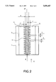
FIG. 2 shows the top view of a magneto-resistive sensor made according to the invention,
FIG. 3 represents the sectional view of a multi-layer magneto-resistive sensor.
The same marks are used for the same element on each figure.
MORE DETAILED DESCRIPTION
FIGS. 1A and 1B show a sectional view and a top view respectively of a magneto-resistive sensor according to prior art. On these figures, a magneto-resistive element 2 is located on a material support 1. This element may be deposited, for example, by cathodic spraying.
The thickness of the magneto-resistive element may, for example, be of the order of 25 nanometers. An insulating layer 3, for example a layer of metal oxide, covers the entire assembly consisting of the magneto-resistive element and the material support. Two pole pieces 4 and 5 are deposited on the insulating layer 3. The pole pieces are preferably made of a low-retentivity magnetic material, for example Sendust alloy. As mentioned previously, each of the two pole pieces partially overlaps the magneto-resistive element by a distance r, in order to improve the transmission of magnetic flux to this element. The two pole pieces, preferably rectangular, are placed parallel to each other. The distance between them, denoted e, forms the air gap of the magneto-resistive sensor. The current, I, passes through the magneto-resistive element 2. This current circulates along the direction of the line AA' that defines the air gap. When there is no variation in the magnetic field, the resistance of element 2 is equal to R. The detected voltage is then written as V=RI. If the magnetic field varies, the resistance of the magneto-resistive element also varies. The change in the detected voltage is then given by the formula ΔV=ΔR×I where ΔR represents the change in the resistance of the magneto-resistive element.
FIG. 2 shows a top view of a magneto-resistive sensor according to the invention.
The magneto-resistive element 2 is then castellated. The two parts of the magneto-resistive element that overlap with the pole pieces over a distance r each consist of a succession of castellations 6.
According to the invention, castellations 6 are laid out such that the current I only flows through the part of the magneto-resistive element located within the air gap. Preferably, the width of the castellations will be L and the spacing between two successive castellations will also be L. However, the invention is applicable to any other configuration that confines the current within the area of the magneto-resistive element located in the air gap.
Therefore the device according to the invention localizes the current solely within the area in which the magnetic field is concentrated.
It is useful if the sensitivity of the magneto-resistive sensor is improved. For example, a magneto-resistive sensor according to the invention, with an air gap e equal to 100 microns and with an overlap r of 10 microns, has a sensitivity gain of the order of 20% with respect to a magneto-resistive sensor according to prior art, in other words without castellations. Since no current passes through overlap zones r, another advantage of the current is that these zones can be extended in order to better collect the magnetic field.
Preferably, the production process for a device according to the invention includes the following main steps:
Deposit the magneto-resistive material on the surface of support 1 by cathodic spraying. As mentioned previously the thickness of the deposit could be, for example, 25 nanometers.
Install a mask, for example made of photosensitive resin, on the layer of magneto-resistive material. This mask has the same shape as the final magneto-resistive element. The width L could be, for example, equal to 10 microns.
Remove the magneto-resistive layer where it is not required.
Remove the mask.
Deposit an insulating layer 3, for example a metal oxide layer, by any method known to the expert in the field. For example, the thickness of the insulating layer could be 200 nanometers.
Deposit a layer of low-retentivity magnetic material or Sendust alloy over the entire previously deposited insulated layer.
Install a mask with the same dimensions as the pole pieces.
Engrave pole pieces.
When manufacturing a read head, the mask installed to define pole pieces is removed so that the magnetic field inscribed on the tape may be read under the optimum conditions. However, when manufacturing a magnetometer, the mask may remain in place since the field to be detected exists throughout the surrounding space.
As mentioned previously, the invention also concerns multi-layer magneto-resistive sensors. As is well-known to the expert in the field, the magneto-resistive element is then made by stacking at least two magnetic layers separated by a non-magnetic layer. The first step in the production process described above is then to deposit the successive layers necessary to build up the magneto-resistive element. FIG. 3 represents the sectional view of a multi-layer magneto-resistive sensor comprising two magneto-resistive layers 2' and 2" (the castellated portions are not shown).
In the preferred construction method described above, the magneto-resistive element is castellated only where the element overlaps with pole pieces. In other construction methods, the magneto-resistive element is castellated up to the zone located in the air gap.

Claims (7)

What is claimed is:
1. A magneto-resistive magnetic sensor comprising:
a magneto-resistive element having a substantially planar surface portion;
two pole pieces separated by a gap and positioned proximally to said magneto-resistive element;
wherein the width of said gap is less than the width of said magneto-resistive element;
wherein the normal projection of said pole pieces onto said substantially planar portion of said magneto-resistive element comprises two disjoint areas of said magneto-resistive element; and
wherein a current flowing through said magneto-resistive element does not substantially flow through said two disjoint areas.
2. A magnetic sensor as set forth in claim 1, wherein each area of said disjoint areas comprises a succession of castellations.
3. A magnetic sensor as set forth in claim 2, wherein said succession of castellations (6) comprises castellations of uniform size and spacing, wherein the width of said castellations is substantially equal to the width of said spacing.
4. A magnetic sensor as set forth in any of the preceding claims, wherein the magneto-resistive element is made of a single material.
5. A magnetic sensor as set forth in one of claims 1-3, wherein the magneto-resistive element is made by stacking a plurality of magnetic layers, each magnetic layer of said plurality of magnetic layers separated by a non-magnetic layer.
6. A magnetic sensor as set forth in claim 2, wherein said castellations extend substantially over the widths of said disjoint areas.
7. A magnetic sensor as set forth in claim 2, wherein a portion or portions of said castellations extend into an area of said magneto-resistive material between said disjoint areas.
US08/355,893 1993-12-14 1994-12-14 Magneto-resistive magnetic field sensor with pole pieces and increased sensitivity Expired - Fee Related US5696447A (en)

Applications Claiming Priority (2)

Application Number Priority Date Filing Date Title
FR9314992 1993-12-14
FR9314992A FR2713782B1 (en) 1993-12-14 1993-12-14 Magnetic sensor with magneto-resistive effect.

Publications (1)

Publication Number Publication Date
US5696447A true US5696447A (en) 1997-12-09

Family

ID=9453899

Family Applications (1)

Application Number Title Priority Date Filing Date
US08/355,893 Expired - Fee Related US5696447A (en) 1993-12-14 1994-12-14 Magneto-resistive magnetic field sensor with pole pieces and increased sensitivity

Country Status (6)

Country Link
US (1) US5696447A (en)
EP (1) EP0658772B1 (en)
JP (1) JPH07210835A (en)
KR (1) KR950019763A (en)
DE (1) DE69430107T2 (en)
FR (1) FR2713782B1 (en)

Cited By (3)

* Cited by examiner, † Cited by third party
Publication number Priority date Publication date Assignee Title
US6304522B1 (en) 1998-01-27 2001-10-16 Thomson-Csf Data medium optical recording/reading device
US20070075890A1 (en) * 2005-08-30 2007-04-05 Jackson John R Electromagnetic impulse survey apparatus and method utilizing a magnetic component electromagnetic antenna
CN109154640A (en) * 2016-05-24 2019-01-04 Tdk株式会社 Magnetic sensor

Families Citing this family (1)

* Cited by examiner, † Cited by third party
Publication number Priority date Publication date Assignee Title
JP2019219182A (en) * 2018-06-15 2019-12-26 Tdk株式会社 Magnetic sensor

Citations (6)

* Cited by examiner, † Cited by third party
Publication number Priority date Publication date Assignee Title
GB2169434A (en) * 1984-11-24 1986-07-09 Magnetic Components Limited Magnetoresistive sensors
US4649447A (en) * 1985-08-15 1987-03-10 International Business Machines Combed MR sensor
US4734644A (en) * 1985-03-20 1988-03-29 Sony Corporation Flux cancelling yoke type magnetic transducer head
WO1992001945A2 (en) * 1990-07-26 1992-02-06 Eastman Kodak Company Miniature high-sensitivity magnetoresistive magnetometer
US5119025A (en) * 1990-07-26 1992-06-02 Eastman Kodak Company High-sensitivity magnetorresistive magnetometer having laminated flux collectors defining an open-loop flux-conducting path
EP0534791A2 (en) * 1991-09-27 1993-03-31 Sharp Kabushiki Kaisha Magnetoresistance effect type thin film magnetic head

Patent Citations (6)

* Cited by examiner, † Cited by third party
Publication number Priority date Publication date Assignee Title
GB2169434A (en) * 1984-11-24 1986-07-09 Magnetic Components Limited Magnetoresistive sensors
US4734644A (en) * 1985-03-20 1988-03-29 Sony Corporation Flux cancelling yoke type magnetic transducer head
US4649447A (en) * 1985-08-15 1987-03-10 International Business Machines Combed MR sensor
WO1992001945A2 (en) * 1990-07-26 1992-02-06 Eastman Kodak Company Miniature high-sensitivity magnetoresistive magnetometer
US5119025A (en) * 1990-07-26 1992-06-02 Eastman Kodak Company High-sensitivity magnetorresistive magnetometer having laminated flux collectors defining an open-loop flux-conducting path
EP0534791A2 (en) * 1991-09-27 1993-03-31 Sharp Kabushiki Kaisha Magnetoresistance effect type thin film magnetic head

Cited By (7)

* Cited by examiner, † Cited by third party
Publication number Priority date Publication date Assignee Title
US6304522B1 (en) 1998-01-27 2001-10-16 Thomson-Csf Data medium optical recording/reading device
US20070075890A1 (en) * 2005-08-30 2007-04-05 Jackson John R Electromagnetic impulse survey apparatus and method utilizing a magnetic component electromagnetic antenna
US7397417B2 (en) * 2005-08-30 2008-07-08 Jackson John R Electromagnetic impulse survey apparatus and method utilizing a magnetic component electromagnetic antenna
CN109154640A (en) * 2016-05-24 2019-01-04 Tdk株式会社 Magnetic sensor
US20190293735A1 (en) * 2016-05-24 2019-09-26 Tdk Corporation Magnetic sensor
US10890630B2 (en) * 2016-05-24 2021-01-12 Tdk Corporation Magnetic sensor
CN109154640B (en) * 2016-05-24 2021-03-23 Tdk株式会社 Magnetic sensor

Also Published As

Publication number Publication date
EP0658772B1 (en) 2002-03-13
KR950019763A (en) 1995-07-24
DE69430107T2 (en) 2002-11-28
FR2713782A1 (en) 1995-06-16
DE69430107D1 (en) 2002-04-18
FR2713782B1 (en) 1996-01-05
EP0658772A1 (en) 1995-06-21
JPH07210835A (en) 1995-08-11

Similar Documents

Publication Publication Date Title
EP0114997B1 (en) Magnetic read head
CA1056502A (en) Eliminating part of magnetic crostalk in magnetoresistive sensors
EP0911810B1 (en) Magnetic tunnel junction devices
US5495378A (en) Magnetoresistive sensor with improved performance and processability
JP2637911B2 (en) Method of manufacturing magnetic head, magnetic tape data storage device, thin film magnetic sensor assembly on substrate, and method of manufacturing magnetoresistive (MR) head
CN86105533A (en) Magnetoresistive read transducer
EP0269129B1 (en) Thin film magnetic head
EP0021392B1 (en) Magnetic transducing head assemblies
EP0211445A1 (en) A magnetoresistive read transducer assembly
EP0171956B1 (en) Permanent magnet biased narrow track magnetoresistive transducer
US5867889A (en) Double self-aligned insulated contiguous junction for flux-guided-MR or yoke-MR head applications
US6795280B1 (en) Tunneling magneto-resistive read head with two-piece free layer
US5523687A (en) Magnetic flux guide having tongues and magnetoresistive transducer incorporating said guide
EP0663661B1 (en) Magnetically capped dual magnetoresistive reproduce head and method of making same
US6075360A (en) Magnetoresistive component having a multilayer strip with a geometrical pattern
US5696447A (en) Magneto-resistive magnetic field sensor with pole pieces and increased sensitivity
US5491606A (en) Planar magnetoresistive head with an improved gap structure
EP0470687B1 (en) Magneto-resistive sensor
EP0573155A2 (en) Magnetoresistive transducer conductor configuration
KR100280300B1 (en) Combined read / write magnetic head
EP0553434B1 (en) Thin film magnetic head
EP0482642B1 (en) Composite magnetoresistive thin-film magnetic head
JP2583851B2 (en) Magnetoresistive magnetic head
JPH05266437A (en) Magnetoresistance effect type head
JP2500519Y2 (en) Magnetoresistive magnetic sensor

Legal Events

Date Code Title Description
AS Assignment

Owner name: THOMSON-CSF

Free format text: ASSIGNMENT OF ASSIGNORS INTEREST;ASSIGNORS:COUTELLIER, JEAN-MARC;BLANCHARD, NICOLAS;VALET, THIERRY;REEL/FRAME:007400/0906

Effective date: 19950315

FEPP Fee payment procedure

Free format text: PAYOR NUMBER ASSIGNED (ORIGINAL EVENT CODE: ASPN); ENTITY STATUS OF PATENT OWNER: LARGE ENTITY

FPAY Fee payment

Year of fee payment: 4

FPAY Fee payment

Year of fee payment: 8

REMI Maintenance fee reminder mailed
LAPS Lapse for failure to pay maintenance fees
STCH Information on status: patent discontinuation

Free format text: PATENT EXPIRED DUE TO NONPAYMENT OF MAINTENANCE FEES UNDER 37 CFR 1.362

FP Lapsed due to failure to pay maintenance fee

Effective date: 20091209