US5689168A - Control circuit for two speed motors - Google Patents
Control circuit for two speed motors Download PDFInfo
- Publication number
- US5689168A US5689168A US08/741,567 US74156796A US5689168A US 5689168 A US5689168 A US 5689168A US 74156796 A US74156796 A US 74156796A US 5689168 A US5689168 A US 5689168A
- Authority
- US
- United States
- Prior art keywords
- speed
- motor
- low speed
- electronic switch
- winding
- Prior art date
- Legal status (The legal status is an assumption and is not a legal conclusion. Google has not performed a legal analysis and makes no representation as to the accuracy of the status listed.)
- Expired - Lifetime
Links
Images


Classifications
-
- H—ELECTRICITY
- H02—GENERATION; CONVERSION OR DISTRIBUTION OF ELECTRIC POWER
- H02P—CONTROL OR REGULATION OF ELECTRIC MOTORS, ELECTRIC GENERATORS OR DYNAMO-ELECTRIC CONVERTERS; CONTROLLING TRANSFORMERS, REACTORS OR CHOKE COILS
- H02P25/00—Arrangements or methods for the control of AC motors characterised by the kind of AC motor or by structural details
- H02P25/02—Arrangements or methods for the control of AC motors characterised by the kind of AC motor or by structural details characterised by the kind of motor
- H02P25/04—Single phase motors, e.g. capacitor motors
-
- H—ELECTRICITY
- H02—GENERATION; CONVERSION OR DISTRIBUTION OF ELECTRIC POWER
- H02P—CONTROL OR REGULATION OF ELECTRIC MOTORS, ELECTRIC GENERATORS OR DYNAMO-ELECTRIC CONVERTERS; CONTROLLING TRANSFORMERS, REACTORS OR CHOKE COILS
- H02P1/00—Arrangements for starting electric motors or dynamo-electric converters
- H02P1/16—Arrangements for starting electric motors or dynamo-electric converters for starting dynamo-electric motors or dynamo-electric converters
- H02P1/42—Arrangements for starting electric motors or dynamo-electric converters for starting dynamo-electric motors or dynamo-electric converters for starting an individual single-phase induction motor
- H02P1/44—Arrangements for starting electric motors or dynamo-electric converters for starting dynamo-electric motors or dynamo-electric converters for starting an individual single-phase induction motor by phase-splitting with a capacitor
Definitions
- This application relates to the art of control circuits and, more particularly, to control circuits for electric motors.
- the invention is particularly applicable for use with a capacitor start two speed motor and will be described with specific reference thereto. However, it will be appreciated that certain features of the invention have broader aspects and can be used in other applications.
- a motor start winding is activated to start a motor and is deactivated once the motor is up to speed. If the motor speed decreases to a predetermined threshold point, the start winding is reactivated until the motor is back up to the proper speed. In motors having centrifugal switches for activating and deactivating the start winding, the reduced motor speed at which the start winding is reactivated is the same regardless of whether the motor is running on the low speed winding or the high speed winding. It would be desirable to have a control arrangement for reactivating the start winding at different reactivating speeds depending upon whether the motor is running on its high speed run winding or on its low speed run winding.
- the improved electronic switching arrangements of the present application are used in a motor control circuit that monitors a reference value correlated to motor power supply voltage and a sensed value correlated to motor current. The two values are compared by a comparator that changes states to activate and deactivate the motor start winding according to whether the sensed value is higher or lower than the reference value.
- a motor control circuit includes a low speed electronic switch in series with a low speed run winding of a motor, a high speed electronic switch in series with a high speed run winding of the motor and an electronic start switch in series with the motor start winding.
- the low speed run winding is activatable only through the low speed electronic switch.
- the high speed run winding is activatable either through the high speed electronic switch or directly through a speed selector switch. When the low speed electronic switch is biased on, the high speed electronic switch is biased off and the speed selector switch is in a position for activating only the low speed run winding.
- the low speed electronic switch When the start winding is reactivated while the motor is running on its low speed run winding, the low speed electronic switch is biased off and the high speed electronic switch is biased on. The high speed run winding is then activated through the high speed electronic switch and the low speed setting of the speed selector switch.
- a detector is provided for detecting whether the motor is running on its low speed run winding to provide different reactivating motor speeds for the start winding depending upon whether the motor is running on its high speed run winding or on its low speed run winding.
- FIGS. 1A and 1B are a schematic illustration of a control circuit in accordance with the present application.
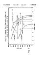
- FIG. 2 is a graph showing motor current versus motor speed
- FIG. 3 is a graph showing resistance versus temperature for a sense resistor used in the control circuit of the present application.
- numerals 1-7 identify the circuit lines that are interrupted at the right side of FIG. 1A to provide a reference for a continuation of the same lines that are identified by the same numbers 1-7 at the left side of FIG. 1B.
- FIGS. 1A and 1B show a motor M connected across lines L1 and L2 of an alternating current power supply 10 through a main switch 12 and a speed selector switch having a high speed position 14 and a low speed position 14a.
- Motor M includes a high speed run winding 16 connected across lines 1 and L2 by lines 17, 18.
- a low speed run winding 19 in series with a low speed electronic switch A is connected across lines 2 and L2 through lines 4, 18 and 20.
- a start winding 21 in series with an electronic start switch B is connected across lines L1 and L2 by lines 18 and 22.
- a capacitor 23 in series with start winding 21 provides a phase displacement of approximately 90° between the start and run winding currents.
- a high speed electronic switch C is connected to low speed electronic switch A by line 3.
- Lines 24 and 25 connect high speed electronic switch C to lines 1 and 2.
- Opto-isolator 30 is used as a voltage isolator and translator between comparator G and triac 33 because the output of comparator G on line 26 and the input to triac 33 on line 36 are at incompatible electrical potentials.
- Low speed electronic switch A is connected by line 3 through a current limiting resistor 37 to triac 38 of high speed electronic switch C.
- Triac 38 is connected through current limiting resistor 39 to high current triac 40.
- Current limiting resistors 41 and 42 cooperate with current limiting resistors 37 and 39 for limiting current to triacs 38 and 40, and help to prevent false triggering.
- Both start winding 21 and high speed run winding 16 are then active for accelerating motor M back up to the proper speed. Once the motor is back up to speed, the output of comparator G on line 26 again goes low to turn on low speed electronic switch A, and turn off electronic start switch B and high speed electronic switch C. The motor then returns to running on low speed run winding 19.
- Electronic start switch B includes current limiting resistors 43, 44 and 45 that also help prevent false triggering of logic triac 46 and high current snubberless triac 47.
- Electronic start switch B is connected with output line 26 of comparator G by lines 5 and 154. When the output of comparator G on line 26 is low, electronic start switch B is off. When the output of comparator G on line 26 goes high, logic triac 46 of electronic start switch B turns on to also turn on high current snubberless triac 47. Start winding 21 is then activated through line 22, triac 47 and line 18.
- High speed electronic switch C is connected in series with high speed run winding 16 only when the speed selector switch is in its low speed setting 14a.
- the circuit through high speed electronic switch C to high speed run winding 16 is interrupted when the speed selector switch is in high speed position 14 because line 2 is disconnected from line L1.
- High speed run winding 16 With the speed selector switch in its high speed position 14, high speed run winding 16 is directly connected across lines 1 and L2 through lines 17 and 18. Thus, there are two alternative paths for activating high speed run winding 16. Low speed run winding 19 and low speed electronic switch A are always deactivated when electronic start switch B and start winding 21 are activated.
- the control circuit of the present application reactivates start winding 21 at different reduced motor speeds depending upon whether the motor is running on high speed run winding 16 through high speed position 14 of the speed selector switch or on low speed run winding 19 through low speed position 14a of the speed selector switch. This is accomplished in part by providing a low speed run winding detector D for determining whether low speed run winding 19 is active.
- Low speed run winding detector D is connected by line 7 to line 4 between low speed electronic switch A and low speed run winding 19.
- low speed electronic switch A When low speed electronic switch A is turned on and a voltage greater than 90 volts ac is present at the connection of line 7 to line 4, the resulting dc voltage provided by detector D at positive input 50 to comparator 52 exceeds the voltage at negative input 54 to comparator 52, and the output of comparator 52 goes high. This adjusts the circuit for reactivating the start winding at a lower motor speed than when motor M is running on its high speed run winding. This aspect of the control circuit will be described in more detail as the description proceeds.
- Low speed run winding detector D includes resistors 56, 58 that form a voltage divider for reducing the magnitude of the line voltage to a certain desired value.
- Diode 60 rectifies line voltage into a positive pulsating dc voltage and is in series with a current limiting resistor 62.
- a zener diode 64 clamps the desired dc voltage value.
- Capacitor 66 filters the positive pulsating voltage into a steady dc voltage, and resistor 68 provides a controlled discharge path for filter capacitor 66.
- Diode 70 and resistor 72 provide a path for rapid discharge of capacitor 66 when low speed electronic switch A is turned off.
- a sense resistor 80 is connected in series with motor M in line 18.
- the sense resistor is a short length of wire.
- a preferred example that has been tested is a 15-inch length of 18 gauge copper wire, with the wire gauge corresponding to American Wire Gauge Standards.
- the current running through motor M correlates to the rotational speed of the motor as shown in the graph of FIG. 2.
- the motor current also runs through sense resistor 80, and measuring the voltage drop across sense resistor 80 is a way of measuring motor current or a value that is correlated to motor current. Because the voltage drop correlates to motor current which in turn correlates to motor speed, the voltage drop also correlates to motor speed.
- the sense resistor could be of other metals, gauges and lengths, and that other kinds of sense resistors could be used.
- the sense resistor preferably is positioned inside the motor housing in close proximity to the motor windings for exposure to approximately the same temperature environment as the motor windings.
- the sense resistor can be positioned in other locations, including outside of the motor housing, as long as the sense resistor is in approximately the same temperature environment as the motor and motor windings.
- motor current changes with variations in the temperature of the motor windings.
- motor current changes that are due solely to temperature variations do not appreciably affect motor speed.
- a control circuit that is sensitive to such changes in motor current could interpret them as motor speed changes and significantly contribute to inaccuracies in the motor rpm trip points at which the start winding is activated and deactivated.
- Line 6 is connected at point 90 between motor M and sense resistor 80, and to positive input 92 of operational amplifier 94 in amplifier E.
- the voltage across sense resistor 80 is amplified by amplifier E for conversion to a dc voltage.
- the input voltage at positive input 92 to operational amplifier 94 is a sine wave in the millivolt range and the output is a positive pulsating dc voltage in the single digit volt range.
- Amplifier E includes an impedance matching resistor 96, and resistors 98, 100 that set the amount of voltage gain provided by the amplifier.
- a peak detector F is connected by line 102 to the output of amplifier E and converts the pulsating positive dc voltage from amplifier E to a steady dc voltage.
- the magnitude of the steady dc voltage is close to the peak of the pulsating dc voltage from amplifier E and correlates to the speed of motor M.
- Peak detector F includes a capacitor 104 that filters the positive pulsating dc voltage into a steady dc voltage, and a diode 106 prevents capacitor 104 from discharging back into amplifier E.
- Resistor 108 provides a controlled discharge path for capacitor 104, and zener diode 110 clamps the desired dc voltage value.
- Input impedance matching resistor 112 is in line 114 connecting the output of peak detector F to the positive input of comparator G.
- the negative input of comparator G is connected by line 120 with voltage reference H that in turn is connected by line 122 to lines 1 and 2 through diodes 124, 126.
- Voltage reference H includes resistors 130, 132 that form a voltage divider for reducing the magnitude of line voltage to a reference voltage value.
- the reference voltage provided by voltage reference H to the negative input of comparator G varies in magnitude with variations in the magnitude of line voltage so that the ratio of the reference voltage to line voltage remains substantially constant. Variations in the magnitude of line voltage also cause changes in motor current and this in turn causes changes in the voltage drop across sense resistor 80 that are substantially proportional to the changes in the reference voltage.
- This provides the control circuit with automatic compensation for changes in motor current caused by line voltage variations because increases and decreases in the reference voltage are substantially matched by corresponding increases and decreases in the voltage drop across sense resistor 80. This improves the accuracy of the motor rpm trip points at which the start winding is deactivated and reactivated. The actual motor rpm trip points do not deviate by more than around plus or minus 150 rpm from the optimum motor rpm trip points.
- Voltage reference H includes a diode 134 that rectifies the sine wave into a positive pulsating dc voltage.
- Capacitor 136 filters the positive pulsating dc voltage into a steady dc voltage, and resistor 138 provides a controlled discharge path for capacitor 136.
- Adc power supply J connected to lines 1 and 2 converts ac line voltage to adc power supply for circuit components requiring adc voltage.
- Adc voltage 140 provided by dc power supply J is connected to other circuit components as indicated at 140a, 140b, 140c, 140d, 140e and 140f.
- Power supply J includes a diode 144 that rectifies line voltage into a positive pulsating dc voltage.
- Capacitor 146 filters the positive pulsating voltage into a steady dc voltage at 140, while zener diode 148 clamps the desired dc voltage value.
- a resistor 150 in series with diode 144 is a current limiting and voltage dropping resistor.
- An inverter K is provided to invert the output of comparator G by use of an inverting comparator 152.
- Line 154 connects the output of comparator G to the negative input 156 of inverting comparator 152 through an impedance matching resistor 158.
- Output line 160 from inverting comparator 152 is connected by line 162 to negative input line 120 of comparator G.
- Positive input line 164 of inverting comparator 152 includes a current limiting resistor 166 and an impedance matching resistor 168.
- Zener diode 170 clamps the positive input to a desired dc voltage value and sets the reference voltage for inverter K.
- Capacitor 172 in line 162 provides hysteresis and pulls the negative input to comparator G higher when the output of inverter K goes high. This helps to prevent chattering of comparator G during switching, i.e., when comparator G changes between its high and low states.
- capacitor 172 pulls the negative input to comparator G lower and helps prevent chattering of comparator G when it changes to its opposite state.
- a start winding gain adjuster P is provided for adjusting the gain of amplifier E when the start winding is inactive.
- the purpose of gain adjuster P is to adjust the gain of amplifier E for achieving proper motor rpm and motor current switching points for activating and deactivating start winding 21.
- npn transistor 180 of gain adjuster P is off because the input voltage on line 154 to negative input 156 of inverting comparator 152 is higher than the reference voltage to positive input 164 and the output on line 160 goes low. Under these conditions, gain adjuster P is inoperative while start winding 21 is active so there is no adjustment in the gain of amplifier E.
- comparator G goes low to deactivate start winding 21, and the reference voltage on line 154 to negative input 156 of inverting comparator 152 is below the reference voltage at positive input 164. This causes the output of inverting comparator 152 to go high and turns on transistor 180 through current limiting resistor 184 connected with the base of the transistor. Resistor 182 of gain adjuster P is then connected in parallel with resistor 100 of amplifier E to provide a higher gain for amplifier E due to the relationship between resistors 100 and 182. When transistor 180 is off, resistor 182 has no effect on amplifier E.
- a low speed run winding gain adjuster R is connected to the output of low speed detector D and the negative input 190 of operational amplifier 94.
- electronic switch A When electronic switch A is on for operating motor M on its low speed run winding 19, the relationship between motor current and motor speed changes as shown in FIG. 2.
- Gain adjuster R adjusts the gain of amplifier E when low speed run winding 24 is active to obtain proper motor rpm and motor current switching points. The switching points being the motor rotational speeds and motor currents at which the start winding is reactivated and deactivated.
- low speed detector D detects a voltage less than 90 volts ac on the connection of line 7 to line 4. Therefore, the voltage at positive input 50 of comparator 52 is less than the reference voltage at negative input 54, and the output of comparator 52 goes low so that transistor 204 remains off and gain adjuster R has no effect on amplifier E when the low speed winding is inactive.
- comparator G goes high when the control circuit calls for activation of the start winding.
- Logic triac 46 of electronic start switch B is then turned on through the connection between lines 5 and 154 to comparator output line 26. When logic triac 46 turns on, this also turns on high current snubberless triac 47 to activate start winding 21.
- the sensed value provided by the voltage drop across sense resistor 80 is constantly monitored, and amplifier E along with peak detector F provide a sensed value input to the positive input of comparator G.
- a reference value is provided to the negative input of comparator G from reference voltage H that monitors line voltage.
- the magnitude of the output from peak detector F correlates to motor current because the voltage drop across sense resistor 80 correlates to motor current which in turn correlates to motor speed as shown in FIG. 2.
- the magnitude of the reference voltage provided by voltage reference H to the negative input of comparator G correlates to the magnitude of line voltage.
- the motor has three different operating conditions.
- the first condition is when both high speed run winding 16 and start winding 21 are active. In this condition, both gain adjusters P and R are inactive. This condition corresponds to curve 250 of FIG. 2 when the motor current is highest and the voltage drop across sense resistor 80 is largest.
- the second condition is when only the low speed run winding is active. In this condition, both gain adjusters P and R are active. This condition corresponds to curve 262 of FIG. 2 when the motor current is lowest and the voltage drop across sense resistor 80 is smallest. Under this condition, amplifier E is provided with the highest gain.
- the third condition is when only the high speed run winding is active. In this condition, gain adjuster P is active and gain adjuster R is inactive. Thus, amplifier E has less gain than in the second motor run condition. This third condition corresponds to curve 260 in FIG. 2 when the motor current is intermediate the motor current in the other two motor run conditions.
- both the low speed gain adjuster R and the start gain adjuster P are on to provide amplifier E with its greatest gain.
- low speed gain adjuster R is off and start gain adjuster P is on so that amplifier E has an intermediate gain.
- both of gain adjusters P and R are off and amplifier E has its lowest gain that is built into it with no boost from either gain adjuster P or R.
- comparator G goes high in response to higher motor currents running through sense resistor 80, and goes low in response to lower motor currents running through sense resistor 80.
- curve 250 shows the correlation between motor speed and motor current when both the start winding and the high speed run winding are active.
- the start winding is deactivated and the motor current drops off as indicated by horizontal arrow lines 252, 254.
- the motor continues to run on only the high speed run winding represented by curve 260 or the low speed run winding represented by curve 262.
- the different gain provided to amplifier E by gain adjuster P alone or by gain adjusters P and R combined makes it possible to reactivate the start winding at different motor speeds depending upon whether the motor is running on the high speed run winding or on the low speed run winding.
- the trip points at which the start winding is activated and deactivated with reference to FIG. 2 are by way of example only and not by way of limitation. Many different trip points may be provided depending upon the application, and the trip points are approximate and may vary by at least plus or minus 150 rpm or even more.
- Adjusting the gain of amplifier E provides an advantageous way of adjusting the motor speed trip points at which the start winding is deactivated and reactivated.
- the amplifier gain can be adjusted by changing the resistance value of resistors 100 and 182 in amplifier circuit E and gain adjuster circuit P. Adjusting the amplifier gain adjusts the magnitude of the difference between the sensed value across sense resistor 80 and the sensed value input that is received by comparator G. This functions to adjust the magnitude of the motor current at which comparator G will go high or low, thereby adjusting the motor speed at which the start winding is deactivated and reactivated. Increasing the amplifier gain provides upward adjustment in the motor speeds at which the start winding is deactivated and reactivated.
- the control circuit provides a start winding control that reactivates the start winding at different motor speeds depending upon whether the motor is connected through the speed selector switch for running on its low speed run winding or its high speed run winding. This is achieved by providing higher gain to the control amplifier when the motor is connected to run on its low speed run winding.
- the low speed gain is activated by a detector that detects when the low speed run winding is active.
- the amplifier and peak detector effectively provide a sensing circuit for sensing a sensed value that correlates to motor current and providing a sensed value input to the comparator.
- the voltage reference provides a reference value to the comparator that correlates to line voltage for comparison with the sensed value to activate or deactivate the start winding.
- the graph of FIG. 2 provides a reference for the motor currents at which the output of the comparator goes high or low to activate or deactivate the start winding.
- the comparator goes high at different motor currents that correlate to different reduced motor speeds depending on whether the high or low speed run winding is connected. This is because connection of the low speed winding activates a low speed gain adjuster for the amplifier.
- both the low speed gain adjuster and the start gain adjuster are active, and the output of the comparator will go high at any motor current greater than about 19 amps. This will deactivate the low speed winding, and turn off both the low speed gain adjuster and the start gain adjuster, while activating the start winding and the high speed winding, and the total motor current moves to curve 250.
- gain adjuster P is on and gain adjuster R is off, and the output of the comparator will go high at any motor current greater than about 28 amps. This will activate the start winding and the total motor current moves to curve 250 while gain adjuster R remains off and gain adjuster P is turned off.
- Voltage reference H provides a reference value that correlates to line voltage and the voltage drop across sense resistor 80 provides a sensed value that correlates to motor current which in turn correlates to motor speed.
- the reference and sensed values provide reference and sensed inputs to comparator G.
Abstract
Description
Claims (10)
Priority Applications (4)
| Application Number | Priority Date | Filing Date | Title |
|---|---|---|---|
| US08/741,567 US5689168A (en) | 1996-10-31 | 1996-10-31 | Control circuit for two speed motors |
| CA002212972A CA2212972C (en) | 1996-10-31 | 1997-08-13 | Control circuit for two speed motors |
| EP97630055A EP0840436A1 (en) | 1996-10-31 | 1997-09-12 | Control circuit for two speed motors |
| JP9282610A JPH10136673A (en) | 1996-10-31 | 1997-09-30 | Control circuit for two-speed motor |
Applications Claiming Priority (1)
| Application Number | Priority Date | Filing Date | Title |
|---|---|---|---|
| US08/741,567 US5689168A (en) | 1996-10-31 | 1996-10-31 | Control circuit for two speed motors |
Publications (1)
| Publication Number | Publication Date |
|---|---|
| US5689168A true US5689168A (en) | 1997-11-18 |
Family
ID=24981250
Family Applications (1)
| Application Number | Title | Priority Date | Filing Date |
|---|---|---|---|
| US08/741,567 Expired - Lifetime US5689168A (en) | 1996-10-31 | 1996-10-31 | Control circuit for two speed motors |
Country Status (4)
| Country | Link |
|---|---|
| US (1) | US5689168A (en) |
| EP (1) | EP0840436A1 (en) |
| JP (1) | JPH10136673A (en) |
| CA (1) | CA2212972C (en) |
Cited By (19)
| Publication number | Priority date | Publication date | Assignee | Title |
|---|---|---|---|---|
| US5973473A (en) * | 1996-10-31 | 1999-10-26 | Therm-O-Disc, Incorporated | Motor control circuit |
| US6160372A (en) * | 1997-07-14 | 2000-12-12 | Robertshaw Controls Company | Solid state motor start method and apparatus |
| US6246207B1 (en) | 1998-06-26 | 2001-06-12 | A. O. Smith Corporation | Method and apparatus for controlling an induction motor |
| US20030137263A1 (en) * | 2002-01-24 | 2003-07-24 | Peterson Gregory A. | Current sensing methods and apparatus in an appliance |
| US20030142982A1 (en) * | 2002-01-24 | 2003-07-31 | Peterson Gregory A. | Appliance control communication methods and apparatus |
| US20040184791A1 (en) * | 2003-03-21 | 2004-09-23 | Sunbeam Products, Inc. | Closed loop feedback method for electric motor |
| US20050025493A1 (en) * | 2003-07-28 | 2005-02-03 | Jurgis Astrauskas | Method and apparatus for using a close proximity probe for optical communication with a device external to the probe |
| US20050025503A1 (en) * | 2003-07-28 | 2005-02-03 | Jurgis Astrauskas | Method and apparatus for operating an optical receiver for low intensity optical communication in a high speed mode |
| US20050025494A1 (en) * | 2003-07-28 | 2005-02-03 | Jurgis Astrauskas | Method and apparatus for improving noise immunity for low intensity optical communication |
| US20050024330A1 (en) * | 2003-07-28 | 2005-02-03 | Jurgis Astrauskas | Method and apparatus for independent control of low intensity indicators used for optical communication in an appliance |
| US20050073422A1 (en) * | 2003-09-18 | 2005-04-07 | Graff Timothy E. | Method and apparatus for enabling optical communication through low intensity indicators in an appliance that uses a vacuum flourescent display |
| US20050156557A1 (en) * | 2003-07-09 | 2005-07-21 | A. O. Smith Corporation | Switch assembly, electric machine having the switch assembly, and method of controlling the same |
| US7243174B2 (en) | 2003-06-24 | 2007-07-10 | Emerson Electric Co. | System and method for communicating with an appliance through an optical interface using a control panel indicator |
| US7315148B2 (en) | 2003-07-28 | 2008-01-01 | Emerson Electric Co. | Method and apparatus for conserving battery for operation of a low intensity optical communication probe |
| WO2008144037A1 (en) | 2007-05-18 | 2008-11-27 | Emerson Climate Technologies, Inc. | Capacity modulated scroll compressor system and method |
| WO2010142152A1 (en) * | 2009-06-09 | 2010-12-16 | 中山大洋电机制造有限公司 | Double speed single phase alternating current motor |
| EP1569325A3 (en) * | 2004-02-24 | 2011-02-16 | Sensata Technologies Massachusetts, Inc. | A motor starter device having reduced power consumption |
| US10908590B2 (en) | 2014-07-18 | 2021-02-02 | Regal Beloit America, Inc. | System and method for adjusting an operation of a motor |
| US20220034143A1 (en) * | 2019-01-25 | 2022-02-03 | Denso Corporation | Opening/closing member control device |
Citations (13)
| Publication number | Priority date | Publication date | Assignee | Title |
|---|---|---|---|---|
| US3414789A (en) * | 1966-05-24 | 1968-12-03 | Essex Wire Corp | Solid-state motor starting circuit |
| US3740631A (en) * | 1971-07-23 | 1973-06-19 | Ecc Corp | Voltage comparator controlled motor starting circuit |
| US4047082A (en) * | 1975-09-04 | 1977-09-06 | Design & Manufacturing Corporation | Variable threshold starting circuit for induction motor |
| US4254343A (en) * | 1978-08-04 | 1981-03-03 | Miller J Vance | Dual load control apparatus |
| US4375613A (en) * | 1976-12-14 | 1983-03-01 | Paul Fuller | Electrical control circuit |
| US4443749A (en) * | 1982-10-07 | 1984-04-17 | A. O. Smith Corporation | Multiple speed split-phase induction motor |
| US4453118A (en) * | 1982-11-08 | 1984-06-05 | Century Electric, Inc. | Starting control circuit for a multispeed A.C. motor |
| US4467257A (en) * | 1982-10-07 | 1984-08-21 | A. O. Smith Corporation | Multiple speed induction motor |
| US4605888A (en) * | 1983-02-21 | 1986-08-12 | Kim In S | Starting winding switching circuit for single-phase induction motors |
| US4622506A (en) * | 1984-12-11 | 1986-11-11 | Pt Components | Load and speed sensitive motor starting circuit |
| US4623829A (en) * | 1984-09-07 | 1986-11-18 | A. O. Smith Corporation | Dual speed induction motor |
| US4658195A (en) * | 1985-05-21 | 1987-04-14 | Pt Components, Inc. | Motor control circuit with automatic restart of cut-in |
| US4804901A (en) * | 1987-11-13 | 1989-02-14 | Kilo-Watt-Ch-Dog, Inc. | Motor starting circuit |
Family Cites Families (3)
| Publication number | Priority date | Publication date | Assignee | Title |
|---|---|---|---|---|
| DE1272439B (en) * | 1963-08-09 | 1968-07-11 | Westinghouse Canada Ltd | Single-phase motor for two different speeds |
| US4862053A (en) * | 1987-08-07 | 1989-08-29 | Reliance Electric Company | Motor starting circuit |
| US5483139A (en) * | 1994-03-14 | 1996-01-09 | General Electric Company | Motor start, reverse and protection system without a starting capacitor |
-
1996
- 1996-10-31 US US08/741,567 patent/US5689168A/en not_active Expired - Lifetime
-
1997
- 1997-08-13 CA CA002212972A patent/CA2212972C/en not_active Expired - Fee Related
- 1997-09-12 EP EP97630055A patent/EP0840436A1/en not_active Ceased
- 1997-09-30 JP JP9282610A patent/JPH10136673A/en active Pending
Patent Citations (13)
| Publication number | Priority date | Publication date | Assignee | Title |
|---|---|---|---|---|
| US3414789A (en) * | 1966-05-24 | 1968-12-03 | Essex Wire Corp | Solid-state motor starting circuit |
| US3740631A (en) * | 1971-07-23 | 1973-06-19 | Ecc Corp | Voltage comparator controlled motor starting circuit |
| US4047082A (en) * | 1975-09-04 | 1977-09-06 | Design & Manufacturing Corporation | Variable threshold starting circuit for induction motor |
| US4375613A (en) * | 1976-12-14 | 1983-03-01 | Paul Fuller | Electrical control circuit |
| US4254343A (en) * | 1978-08-04 | 1981-03-03 | Miller J Vance | Dual load control apparatus |
| US4467257A (en) * | 1982-10-07 | 1984-08-21 | A. O. Smith Corporation | Multiple speed induction motor |
| US4443749A (en) * | 1982-10-07 | 1984-04-17 | A. O. Smith Corporation | Multiple speed split-phase induction motor |
| US4453118A (en) * | 1982-11-08 | 1984-06-05 | Century Electric, Inc. | Starting control circuit for a multispeed A.C. motor |
| US4605888A (en) * | 1983-02-21 | 1986-08-12 | Kim In S | Starting winding switching circuit for single-phase induction motors |
| US4623829A (en) * | 1984-09-07 | 1986-11-18 | A. O. Smith Corporation | Dual speed induction motor |
| US4622506A (en) * | 1984-12-11 | 1986-11-11 | Pt Components | Load and speed sensitive motor starting circuit |
| US4658195A (en) * | 1985-05-21 | 1987-04-14 | Pt Components, Inc. | Motor control circuit with automatic restart of cut-in |
| US4804901A (en) * | 1987-11-13 | 1989-02-14 | Kilo-Watt-Ch-Dog, Inc. | Motor starting circuit |
Cited By (32)
| Publication number | Priority date | Publication date | Assignee | Title |
|---|---|---|---|---|
| US5973473A (en) * | 1996-10-31 | 1999-10-26 | Therm-O-Disc, Incorporated | Motor control circuit |
| US6160372A (en) * | 1997-07-14 | 2000-12-12 | Robertshaw Controls Company | Solid state motor start method and apparatus |
| US6246207B1 (en) | 1998-06-26 | 2001-06-12 | A. O. Smith Corporation | Method and apparatus for controlling an induction motor |
| US7030773B2 (en) | 2002-01-24 | 2006-04-18 | Emerson Electric Company | System and method for communicating with an appliance through a light emitting diode |
| US20030170033A1 (en) * | 2002-01-24 | 2003-09-11 | Peterson Gregory A. | System and method for communicating with an appliance through a light emitting diode |
| US6825626B2 (en) | 2002-01-24 | 2004-11-30 | Emerson Electric Co. | Current sensing methods and apparatus in an appliance |
| US6919815B2 (en) | 2002-01-24 | 2005-07-19 | Emerson Electric Co. | Appliance control communication methods and apparatus |
| WO2003063333A1 (en) * | 2002-01-24 | 2003-07-31 | Emerson Electric Co. | Current sensing methods and apparatus in an appliance |
| US20030142982A1 (en) * | 2002-01-24 | 2003-07-31 | Peterson Gregory A. | Appliance control communication methods and apparatus |
| US20030137263A1 (en) * | 2002-01-24 | 2003-07-24 | Peterson Gregory A. | Current sensing methods and apparatus in an appliance |
| US20040184791A1 (en) * | 2003-03-21 | 2004-09-23 | Sunbeam Products, Inc. | Closed loop feedback method for electric motor |
| US7243174B2 (en) | 2003-06-24 | 2007-07-10 | Emerson Electric Co. | System and method for communicating with an appliance through an optical interface using a control panel indicator |
| US20050156557A1 (en) * | 2003-07-09 | 2005-07-21 | A. O. Smith Corporation | Switch assembly, electric machine having the switch assembly, and method of controlling the same |
| US7042192B2 (en) * | 2003-07-09 | 2006-05-09 | A.O. Smith Corporation | Switch assembly, electric machine having the switch assembly, and method of controlling the same |
| US20050025494A1 (en) * | 2003-07-28 | 2005-02-03 | Jurgis Astrauskas | Method and apparatus for improving noise immunity for low intensity optical communication |
| US7321732B2 (en) | 2003-07-28 | 2008-01-22 | Emerson Electric Co. | Method and apparatus for improving noise immunity for low intensity optical communication |
| US7315148B2 (en) | 2003-07-28 | 2008-01-01 | Emerson Electric Co. | Method and apparatus for conserving battery for operation of a low intensity optical communication probe |
| US20050024330A1 (en) * | 2003-07-28 | 2005-02-03 | Jurgis Astrauskas | Method and apparatus for independent control of low intensity indicators used for optical communication in an appliance |
| US20050025503A1 (en) * | 2003-07-28 | 2005-02-03 | Jurgis Astrauskas | Method and apparatus for operating an optical receiver for low intensity optical communication in a high speed mode |
| US20050025493A1 (en) * | 2003-07-28 | 2005-02-03 | Jurgis Astrauskas | Method and apparatus for using a close proximity probe for optical communication with a device external to the probe |
| US7091932B2 (en) | 2003-07-28 | 2006-08-15 | Emerson Electric Co. | Method and apparatus for independent control of low intensity indicators used for optical communication in an appliance |
| US7280769B2 (en) | 2003-07-28 | 2007-10-09 | Emerson Electric Co. | Method and apparatus for operating an optical receiver for low intensity optical communication in a high speed mode |
| US20050073422A1 (en) * | 2003-09-18 | 2005-04-07 | Graff Timothy E. | Method and apparatus for enabling optical communication through low intensity indicators in an appliance that uses a vacuum flourescent display |
| US7095333B2 (en) | 2003-09-18 | 2006-08-22 | Emerson Electric Company | Method and apparatus for enabling optical communication through low intensity indicators in an appliance that uses a vacuum fluorescent display |
| EP1569325A3 (en) * | 2004-02-24 | 2011-02-16 | Sensata Technologies Massachusetts, Inc. | A motor starter device having reduced power consumption |
| WO2008144037A1 (en) | 2007-05-18 | 2008-11-27 | Emerson Climate Technologies, Inc. | Capacity modulated scroll compressor system and method |
| WO2010142152A1 (en) * | 2009-06-09 | 2010-12-16 | 中山大洋电机制造有限公司 | Double speed single phase alternating current motor |
| US20120062165A1 (en) * | 2009-06-09 | 2012-03-15 | Zhongshan Broad-Ocean Motor Manufacturing Co., Ltd. | Dual-speed single-phase ac motor |
| US8237395B2 (en) * | 2009-06-09 | 2012-08-07 | Zhongshan Broad-Ocean Motor Manufacturing Co., Ltd. | Dual-speed single-phase AC motor |
| US10908590B2 (en) | 2014-07-18 | 2021-02-02 | Regal Beloit America, Inc. | System and method for adjusting an operation of a motor |
| US20220034143A1 (en) * | 2019-01-25 | 2022-02-03 | Denso Corporation | Opening/closing member control device |
| US11788337B2 (en) * | 2019-01-25 | 2023-10-17 | Denso Corporation | Opening/closing member control device |
Also Published As
| Publication number | Publication date |
|---|---|
| CA2212972A1 (en) | 1998-04-30 |
| CA2212972C (en) | 2000-05-09 |
| JPH10136673A (en) | 1998-05-22 |
| EP0840436A1 (en) | 1998-05-06 |
Similar Documents
| Publication | Publication Date | Title |
|---|---|---|
| US5689168A (en) | Control circuit for two speed motors | |
| US5892349A (en) | Control circuit for two speed motors | |
| US5973473A (en) | Motor control circuit | |
| US4375613A (en) | Electrical control circuit | |
| US4622506A (en) | Load and speed sensitive motor starting circuit | |
| US4604563A (en) | Electronic switch for starting AC motor | |
| US4651077A (en) | Start switch for a single phase AC motor | |
| KR100488528B1 (en) | Power supply device for motor | |
| JP4188237B2 (en) | Overcurrent protection of motor control circuit | |
| US4517502A (en) | Load monitoring circuit for electric motors | |
| US5448175A (en) | Current detecting circuit | |
| KR0132521B1 (en) | Dc motor over-current detection apparatus | |
| US4525660A (en) | Control apparatus for inverter | |
| US4328433A (en) | Proximity switch | |
| JPH07501200A (en) | Device for regulating supply current | |
| US4524309A (en) | Safety control device of commutator motors | |
| EP0572755B1 (en) | Turn-on control circuit for electric devices | |
| US4381531A (en) | Alternating current motor protection system | |
| US3792313A (en) | Timing control circuit for solid state protective relays for providing novel control of the pickup and timing circuits provided therein | |
| US5235265A (en) | Multi-level motor load sensing circuit | |
| US5410187A (en) | Output circuit for controlling a relay which has capability for operating with wide range of input voltages | |
| KR100207002B1 (en) | Inverter with dynamic damping circuit | |
| EP0088769A4 (en) | Inductive load driver protection circuits having minimal power dissipation. | |
| JP3616028B2 (en) | Rise control circuit used in switching converter | |
| JPH08107697A (en) | Anomaly detecting circuit for dc fan motor |
Legal Events
| Date | Code | Title | Description |
|---|---|---|---|
| AS | Assignment |
Owner name: THERM-O-DISC, INCORPORATED, OHIO Free format text: ASSIGNMENT OF ASSIGNORS INTEREST;ASSIGNORS:BOGWICZ, ROBERT R.;DURKEE, JOHN E.;ANDERSON, JASON S.;REEL/FRAME:008318/0838 Effective date: 19961025 |
|
| FEPP | Fee payment procedure |
Free format text: PAYOR NUMBER ASSIGNED (ORIGINAL EVENT CODE: ASPN); ENTITY STATUS OF PATENT OWNER: LARGE ENTITY |
|
| STCF | Information on status: patent grant |
Free format text: PATENTED CASE |
|
| FPAY | Fee payment |
Year of fee payment: 4 |
|
| AS | Assignment |
Owner name: EMERSON ELECTRIC CO., MISSOURI Free format text: ASSIGNMENT OF ASSIGNORS INTEREST;ASSIGNOR:THERM-O-DISC, INCORPORATED;REEL/FRAME:015991/0480 Effective date: 20050504 |
|
| FPAY | Fee payment |
Year of fee payment: 8 |
|
| FPAY | Fee payment |
Year of fee payment: 12 |
|
| AS | Assignment |
Owner name: NIDEC MOTOR CORPORATION, MISSOURI Free format text: ASSIGNMENT OF ASSIGNORS INTEREST;ASSIGNOR:EMERSON ELECTRIC CO.;REEL/FRAME:025651/0747 Effective date: 20100924 |