US5689141A - Compressor drive system for a natural gas liquefaction plant having an electric motor generator to feed excess power to the main power source - Google Patents
Compressor drive system for a natural gas liquefaction plant having an electric motor generator to feed excess power to the main power source Download PDFInfo
- Publication number
- US5689141A US5689141A US08/458,322 US45832295A US5689141A US 5689141 A US5689141 A US 5689141A US 45832295 A US45832295 A US 45832295A US 5689141 A US5689141 A US 5689141A
- Authority
- US
- United States
- Prior art keywords
- power
- compressor
- gas turbine
- electric
- gas
- Prior art date
- Legal status (The legal status is an assumption and is not a legal conclusion. Google has not performed a legal analysis and makes no representation as to the accuracy of the status listed.)
- Expired - Lifetime
Links
- VNWKTOKETHGBQD-UHFFFAOYSA-N methane Chemical compound C VNWKTOKETHGBQD-UHFFFAOYSA-N 0.000 title claims abstract description 90
- 239000003345 natural gas Substances 0.000 title claims abstract description 44
- 239000007789 gas Substances 0.000 claims abstract description 125
- 239000003507 refrigerant Substances 0.000 claims abstract description 53
- 238000005057 refrigeration Methods 0.000 claims abstract description 20
- 239000013589 supplement Substances 0.000 claims abstract description 6
- ATUOYWHBWRKTHZ-UHFFFAOYSA-N Propane Chemical compound CCC ATUOYWHBWRKTHZ-UHFFFAOYSA-N 0.000 claims description 74
- 239000001294 propane Substances 0.000 claims description 37
- 230000001360 synchronised effect Effects 0.000 claims description 33
- 239000000446 fuel Substances 0.000 abstract description 6
- 230000001932 seasonal effect Effects 0.000 abstract description 6
- 230000000694 effects Effects 0.000 abstract description 2
- 238000001816 cooling Methods 0.000 description 8
- 230000007423 decrease Effects 0.000 description 5
- 238000004519 manufacturing process Methods 0.000 description 5
- 239000013535 sea water Substances 0.000 description 4
- 239000000498 cooling water Substances 0.000 description 3
- 239000003949 liquefied natural gas Substances 0.000 description 3
- 238000000034 method Methods 0.000 description 3
- 239000000203 mixture Substances 0.000 description 3
- IJGRMHOSHXDMSA-UHFFFAOYSA-N Atomic nitrogen Chemical compound N#N IJGRMHOSHXDMSA-UHFFFAOYSA-N 0.000 description 2
- CURLTUGMZLYLDI-UHFFFAOYSA-N Carbon dioxide Chemical compound O=C=O CURLTUGMZLYLDI-UHFFFAOYSA-N 0.000 description 2
- 239000003570 air Substances 0.000 description 2
- 239000012080 ambient air Substances 0.000 description 2
- 230000005494 condensation Effects 0.000 description 2
- 238000009833 condensation Methods 0.000 description 2
- RWSOTUBLDIXVET-UHFFFAOYSA-N Dihydrogen sulfide Chemical compound S RWSOTUBLDIXVET-UHFFFAOYSA-N 0.000 description 1
- OTMSDBZUPAUEDD-UHFFFAOYSA-N Ethane Chemical compound CC OTMSDBZUPAUEDD-UHFFFAOYSA-N 0.000 description 1
- 150000001412 amines Chemical class 0.000 description 1
- 239000001569 carbon dioxide Substances 0.000 description 1
- 229910002092 carbon dioxide Inorganic materials 0.000 description 1
- 238000010586 diagram Methods 0.000 description 1
- 230000005611 electricity Effects 0.000 description 1
- 238000005265 energy consumption Methods 0.000 description 1
- 229910000037 hydrogen sulfide Inorganic materials 0.000 description 1
- 230000006698 induction Effects 0.000 description 1
- 229910052757 nitrogen Inorganic materials 0.000 description 1
- 230000000153 supplemental effect Effects 0.000 description 1
- 230000001502 supplementing effect Effects 0.000 description 1
- 239000002699 waste material Substances 0.000 description 1
- XLYOFNOQVPJJNP-UHFFFAOYSA-N water Substances O XLYOFNOQVPJJNP-UHFFFAOYSA-N 0.000 description 1
Images

Classifications
-
- F—MECHANICAL ENGINEERING; LIGHTING; HEATING; WEAPONS; BLASTING
- F01—MACHINES OR ENGINES IN GENERAL; ENGINE PLANTS IN GENERAL; STEAM ENGINES
- F01D—NON-POSITIVE DISPLACEMENT MACHINES OR ENGINES, e.g. STEAM TURBINES
- F01D15/00—Adaptations of machines or engines for special use; Combinations of engines with devices driven thereby
- F01D15/10—Adaptations for driving, or combinations with, electric generators
-
- F—MECHANICAL ENGINEERING; LIGHTING; HEATING; WEAPONS; BLASTING
- F25—REFRIGERATION OR COOLING; COMBINED HEATING AND REFRIGERATION SYSTEMS; HEAT PUMP SYSTEMS; MANUFACTURE OR STORAGE OF ICE; LIQUEFACTION SOLIDIFICATION OF GASES
- F25B—REFRIGERATION MACHINES, PLANTS OR SYSTEMS; COMBINED HEATING AND REFRIGERATION SYSTEMS; HEAT PUMP SYSTEMS
- F25B11/00—Compression machines, plants or systems, using turbines, e.g. gas turbines
-
- F—MECHANICAL ENGINEERING; LIGHTING; HEATING; WEAPONS; BLASTING
- F25—REFRIGERATION OR COOLING; COMBINED HEATING AND REFRIGERATION SYSTEMS; HEAT PUMP SYSTEMS; MANUFACTURE OR STORAGE OF ICE; LIQUEFACTION SOLIDIFICATION OF GASES
- F25B—REFRIGERATION MACHINES, PLANTS OR SYSTEMS; COMBINED HEATING AND REFRIGERATION SYSTEMS; HEAT PUMP SYSTEMS
- F25B7/00—Compression machines, plants or systems, with cascade operation, i.e. with two or more circuits, the heat from the condenser of one circuit being absorbed by the evaporator of the next circuit
-
- F—MECHANICAL ENGINEERING; LIGHTING; HEATING; WEAPONS; BLASTING
- F25—REFRIGERATION OR COOLING; COMBINED HEATING AND REFRIGERATION SYSTEMS; HEAT PUMP SYSTEMS; MANUFACTURE OR STORAGE OF ICE; LIQUEFACTION SOLIDIFICATION OF GASES
- F25J—LIQUEFACTION, SOLIDIFICATION OR SEPARATION OF GASES OR GASEOUS OR LIQUEFIED GASEOUS MIXTURES BY PRESSURE AND COLD TREATMENT OR BY BRINGING THEM INTO THE SUPERCRITICAL STATE
- F25J1/00—Processes or apparatus for liquefying or solidifying gases or gaseous mixtures
- F25J1/0002—Processes or apparatus for liquefying or solidifying gases or gaseous mixtures characterised by the fluid to be liquefied
- F25J1/0022—Hydrocarbons, e.g. natural gas
-
- F—MECHANICAL ENGINEERING; LIGHTING; HEATING; WEAPONS; BLASTING
- F25—REFRIGERATION OR COOLING; COMBINED HEATING AND REFRIGERATION SYSTEMS; HEAT PUMP SYSTEMS; MANUFACTURE OR STORAGE OF ICE; LIQUEFACTION SOLIDIFICATION OF GASES
- F25J—LIQUEFACTION, SOLIDIFICATION OR SEPARATION OF GASES OR GASEOUS OR LIQUEFIED GASEOUS MIXTURES BY PRESSURE AND COLD TREATMENT OR BY BRINGING THEM INTO THE SUPERCRITICAL STATE
- F25J1/00—Processes or apparatus for liquefying or solidifying gases or gaseous mixtures
- F25J1/003—Processes or apparatus for liquefying or solidifying gases or gaseous mixtures characterised by the kind of cold generation within the liquefaction unit for compensating heat leaks and liquid production
- F25J1/0047—Processes or apparatus for liquefying or solidifying gases or gaseous mixtures characterised by the kind of cold generation within the liquefaction unit for compensating heat leaks and liquid production using an "external" refrigerant stream in a closed vapor compression cycle
- F25J1/0052—Processes or apparatus for liquefying or solidifying gases or gaseous mixtures characterised by the kind of cold generation within the liquefaction unit for compensating heat leaks and liquid production using an "external" refrigerant stream in a closed vapor compression cycle by vaporising a liquid refrigerant stream
- F25J1/0055—Processes or apparatus for liquefying or solidifying gases or gaseous mixtures characterised by the kind of cold generation within the liquefaction unit for compensating heat leaks and liquid production using an "external" refrigerant stream in a closed vapor compression cycle by vaporising a liquid refrigerant stream originating from an incorporated cascade
-
- F—MECHANICAL ENGINEERING; LIGHTING; HEATING; WEAPONS; BLASTING
- F25—REFRIGERATION OR COOLING; COMBINED HEATING AND REFRIGERATION SYSTEMS; HEAT PUMP SYSTEMS; MANUFACTURE OR STORAGE OF ICE; LIQUEFACTION SOLIDIFICATION OF GASES
- F25J—LIQUEFACTION, SOLIDIFICATION OR SEPARATION OF GASES OR GASEOUS OR LIQUEFIED GASEOUS MIXTURES BY PRESSURE AND COLD TREATMENT OR BY BRINGING THEM INTO THE SUPERCRITICAL STATE
- F25J1/00—Processes or apparatus for liquefying or solidifying gases or gaseous mixtures
- F25J1/02—Processes or apparatus for liquefying or solidifying gases or gaseous mixtures requiring the use of refrigeration, e.g. of helium or hydrogen ; Details and kind of the refrigeration system used; Integration with other units or processes; Controlling aspects of the process
- F25J1/0211—Processes or apparatus for liquefying or solidifying gases or gaseous mixtures requiring the use of refrigeration, e.g. of helium or hydrogen ; Details and kind of the refrigeration system used; Integration with other units or processes; Controlling aspects of the process using a multi-component refrigerant [MCR] fluid in a closed vapor compression cycle
- F25J1/0214—Processes or apparatus for liquefying or solidifying gases or gaseous mixtures requiring the use of refrigeration, e.g. of helium or hydrogen ; Details and kind of the refrigeration system used; Integration with other units or processes; Controlling aspects of the process using a multi-component refrigerant [MCR] fluid in a closed vapor compression cycle as a dual level refrigeration cascade with at least one MCR cycle
- F25J1/0215—Processes or apparatus for liquefying or solidifying gases or gaseous mixtures requiring the use of refrigeration, e.g. of helium or hydrogen ; Details and kind of the refrigeration system used; Integration with other units or processes; Controlling aspects of the process using a multi-component refrigerant [MCR] fluid in a closed vapor compression cycle as a dual level refrigeration cascade with at least one MCR cycle with one SCR cycle
- F25J1/0216—Processes or apparatus for liquefying or solidifying gases or gaseous mixtures requiring the use of refrigeration, e.g. of helium or hydrogen ; Details and kind of the refrigeration system used; Integration with other units or processes; Controlling aspects of the process using a multi-component refrigerant [MCR] fluid in a closed vapor compression cycle as a dual level refrigeration cascade with at least one MCR cycle with one SCR cycle using a C3 pre-cooling cycle
-
- F—MECHANICAL ENGINEERING; LIGHTING; HEATING; WEAPONS; BLASTING
- F25—REFRIGERATION OR COOLING; COMBINED HEATING AND REFRIGERATION SYSTEMS; HEAT PUMP SYSTEMS; MANUFACTURE OR STORAGE OF ICE; LIQUEFACTION SOLIDIFICATION OF GASES
- F25J—LIQUEFACTION, SOLIDIFICATION OR SEPARATION OF GASES OR GASEOUS OR LIQUEFIED GASEOUS MIXTURES BY PRESSURE AND COLD TREATMENT OR BY BRINGING THEM INTO THE SUPERCRITICAL STATE
- F25J1/00—Processes or apparatus for liquefying or solidifying gases or gaseous mixtures
- F25J1/02—Processes or apparatus for liquefying or solidifying gases or gaseous mixtures requiring the use of refrigeration, e.g. of helium or hydrogen ; Details and kind of the refrigeration system used; Integration with other units or processes; Controlling aspects of the process
- F25J1/0243—Start-up or control of the process; Details of the apparatus used; Details of the refrigerant compression system used
- F25J1/0244—Operation; Control and regulation; Instrumentation
- F25J1/0245—Different modes, i.e. 'runs', of operation; Process control
- F25J1/0247—Different modes, i.e. 'runs', of operation; Process control start-up of the process
-
- F—MECHANICAL ENGINEERING; LIGHTING; HEATING; WEAPONS; BLASTING
- F25—REFRIGERATION OR COOLING; COMBINED HEATING AND REFRIGERATION SYSTEMS; HEAT PUMP SYSTEMS; MANUFACTURE OR STORAGE OF ICE; LIQUEFACTION SOLIDIFICATION OF GASES
- F25J—LIQUEFACTION, SOLIDIFICATION OR SEPARATION OF GASES OR GASEOUS OR LIQUEFIED GASEOUS MIXTURES BY PRESSURE AND COLD TREATMENT OR BY BRINGING THEM INTO THE SUPERCRITICAL STATE
- F25J1/00—Processes or apparatus for liquefying or solidifying gases or gaseous mixtures
- F25J1/02—Processes or apparatus for liquefying or solidifying gases or gaseous mixtures requiring the use of refrigeration, e.g. of helium or hydrogen ; Details and kind of the refrigeration system used; Integration with other units or processes; Controlling aspects of the process
- F25J1/0243—Start-up or control of the process; Details of the apparatus used; Details of the refrigerant compression system used
- F25J1/0279—Compression of refrigerant or internal recycle fluid, e.g. kind of compressor, accumulator, suction drum etc.
- F25J1/0281—Compression of refrigerant or internal recycle fluid, e.g. kind of compressor, accumulator, suction drum etc. characterised by the type of prime driver, e.g. hot gas expander
- F25J1/0283—Gas turbine as the prime mechanical driver
-
- F—MECHANICAL ENGINEERING; LIGHTING; HEATING; WEAPONS; BLASTING
- F25—REFRIGERATION OR COOLING; COMBINED HEATING AND REFRIGERATION SYSTEMS; HEAT PUMP SYSTEMS; MANUFACTURE OR STORAGE OF ICE; LIQUEFACTION SOLIDIFICATION OF GASES
- F25J—LIQUEFACTION, SOLIDIFICATION OR SEPARATION OF GASES OR GASEOUS OR LIQUEFIED GASEOUS MIXTURES BY PRESSURE AND COLD TREATMENT OR BY BRINGING THEM INTO THE SUPERCRITICAL STATE
- F25J1/00—Processes or apparatus for liquefying or solidifying gases or gaseous mixtures
- F25J1/02—Processes or apparatus for liquefying or solidifying gases or gaseous mixtures requiring the use of refrigeration, e.g. of helium or hydrogen ; Details and kind of the refrigeration system used; Integration with other units or processes; Controlling aspects of the process
- F25J1/0243—Start-up or control of the process; Details of the apparatus used; Details of the refrigerant compression system used
- F25J1/0279—Compression of refrigerant or internal recycle fluid, e.g. kind of compressor, accumulator, suction drum etc.
- F25J1/0285—Combination of different types of drivers mechanically coupled to the same refrigerant compressor, possibly split on multiple compressor casings
- F25J1/0287—Combination of different types of drivers mechanically coupled to the same refrigerant compressor, possibly split on multiple compressor casings including an electrical motor
-
- F—MECHANICAL ENGINEERING; LIGHTING; HEATING; WEAPONS; BLASTING
- F25—REFRIGERATION OR COOLING; COMBINED HEATING AND REFRIGERATION SYSTEMS; HEAT PUMP SYSTEMS; MANUFACTURE OR STORAGE OF ICE; LIQUEFACTION SOLIDIFICATION OF GASES
- F25J—LIQUEFACTION, SOLIDIFICATION OR SEPARATION OF GASES OR GASEOUS OR LIQUEFIED GASEOUS MIXTURES BY PRESSURE AND COLD TREATMENT OR BY BRINGING THEM INTO THE SUPERCRITICAL STATE
- F25J1/00—Processes or apparatus for liquefying or solidifying gases or gaseous mixtures
- F25J1/02—Processes or apparatus for liquefying or solidifying gases or gaseous mixtures requiring the use of refrigeration, e.g. of helium or hydrogen ; Details and kind of the refrigeration system used; Integration with other units or processes; Controlling aspects of the process
- F25J1/0243—Start-up or control of the process; Details of the apparatus used; Details of the refrigerant compression system used
- F25J1/0279—Compression of refrigerant or internal recycle fluid, e.g. kind of compressor, accumulator, suction drum etc.
- F25J1/0292—Refrigerant compression by cold or cryogenic suction of the refrigerant gas
-
- F—MECHANICAL ENGINEERING; LIGHTING; HEATING; WEAPONS; BLASTING
- F25—REFRIGERATION OR COOLING; COMBINED HEATING AND REFRIGERATION SYSTEMS; HEAT PUMP SYSTEMS; MANUFACTURE OR STORAGE OF ICE; LIQUEFACTION SOLIDIFICATION OF GASES
- F25J—LIQUEFACTION, SOLIDIFICATION OR SEPARATION OF GASES OR GASEOUS OR LIQUEFIED GASEOUS MIXTURES BY PRESSURE AND COLD TREATMENT OR BY BRINGING THEM INTO THE SUPERCRITICAL STATE
- F25J1/00—Processes or apparatus for liquefying or solidifying gases or gaseous mixtures
- F25J1/02—Processes or apparatus for liquefying or solidifying gases or gaseous mixtures requiring the use of refrigeration, e.g. of helium or hydrogen ; Details and kind of the refrigeration system used; Integration with other units or processes; Controlling aspects of the process
- F25J1/0243—Start-up or control of the process; Details of the apparatus used; Details of the refrigerant compression system used
- F25J1/0279—Compression of refrigerant or internal recycle fluid, e.g. kind of compressor, accumulator, suction drum etc.
- F25J1/0298—Safety aspects and control of the refrigerant compression system, e.g. anti-surge control
-
- F—MECHANICAL ENGINEERING; LIGHTING; HEATING; WEAPONS; BLASTING
- F25—REFRIGERATION OR COOLING; COMBINED HEATING AND REFRIGERATION SYSTEMS; HEAT PUMP SYSTEMS; MANUFACTURE OR STORAGE OF ICE; LIQUEFACTION SOLIDIFICATION OF GASES
- F25J—LIQUEFACTION, SOLIDIFICATION OR SEPARATION OF GASES OR GASEOUS OR LIQUEFIED GASEOUS MIXTURES BY PRESSURE AND COLD TREATMENT OR BY BRINGING THEM INTO THE SUPERCRITICAL STATE
- F25J2220/00—Processes or apparatus involving steps for the removal of impurities
- F25J2220/60—Separating impurities from natural gas, e.g. mercury, cyclic hydrocarbons
- F25J2220/64—Separating heavy hydrocarbons, e.g. NGL, LPG, C4+ hydrocarbons or heavy condensates in general
-
- F—MECHANICAL ENGINEERING; LIGHTING; HEATING; WEAPONS; BLASTING
- F25—REFRIGERATION OR COOLING; COMBINED HEATING AND REFRIGERATION SYSTEMS; HEAT PUMP SYSTEMS; MANUFACTURE OR STORAGE OF ICE; LIQUEFACTION SOLIDIFICATION OF GASES
- F25J—LIQUEFACTION, SOLIDIFICATION OR SEPARATION OF GASES OR GASEOUS OR LIQUEFIED GASEOUS MIXTURES BY PRESSURE AND COLD TREATMENT OR BY BRINGING THEM INTO THE SUPERCRITICAL STATE
- F25J2280/00—Control of the process or apparatus
- F25J2280/10—Control for or during start-up and cooling down of the installation
Definitions
- the present invention relates to a compressor drive system for pressurizing a refrigerant for cooling natural gas in a natural gas liquefaction plant.
- the necessary energy is generated by using natural gas, and supplied in two forms, thermal energy and kinetic energy.
- the thermal energy is produced by boilers and furnaces, and the kinetic energy is produced primarily by gas turbines.
- a primary user of the kinetic energy is the compressors for pressurizing refrigerants for cooling natural gas.
- the purified natural gas is cooled in two stages. More specifically, a propane refrigerant is used for preliminary cooling of the natural gas to a temperature of approximately -30° C., and a mixed refrigerant is used for cooling the natural gas below the natural gas liquefaction temperature of -162° C.
- a propane refrigerant is used for preliminary cooling of the natural gas to a temperature of approximately -30° C.
- a mixed refrigerant is used for cooling the natural gas below the natural gas liquefaction temperature of -162° C.
- Each of these refrigerants is circulated in an independent closed loop forming an individual refrigeration cycle.
- a dedicated gas turbine is installed in each of these refrigeration cycles to drive the corresponding compressor.
- the in-plant power station which is normally powered by a dedicated gas turbine in a similar manner as the compressors.
- the in-plant power station supplies electric power to drive the motors for pumps, small compressors, blowers, and other auxiliary equipment and supplied to other users of electric power within the plant.
- a natural gas liquefaction plant is normally provided with at least three gas turbines, two of them for pressurizing refrigerants, the remaining one for driving an in-plant power generator.
- a natural gas liquefaction plant is normally extremely large in capacity so as to be capable of processing a large volume of natural gas, and the overall energy consumption of the plant is therefore enormous. Accordingly, the operation cost and the investment cost for the facilities for supplying energy to such a plant are substantial.
- the gas turbines for driving the compressors for refrigerants are large in size, and highly expensive, they account for a substantial portion of the overall cost of operating and constructing the natural gas liquefaction plant.
- the manufacturers capable of manufacturing gas turbines of this class are very few in number worldwide, and the gas turbines are available only in specific sizes and limited specifications for each of the manufacturers.
- the maximum available sizes of the gas turbines for driving the compressors dictate the maximum capacity of the refrigeration facilities composed of compressors, condensers and other components, and serve as a de facto deciding factor in determining the production capacity of the natural gas liquefaction plant.
- a gas turbine is normally designed so as to be most efficient when it is operated at its rated maximum power output, and its efficiency significantly drops when it is operated at such a partial load condition. Therefore, when the gas turbine is operated under a partial load condition, there will be a substantial waste in the fuel consumption, and the operation cost will increase.
- a stand-by unit is normally prepared for each of the rotating machines such as pumps and compressors so that even when any one of the rotating machines should fail the plant can be restarted quickly simply by switching valves.
- Stand-by units are also prepared for the generator for the in-plant power station, and the gas turbine for driving the power generator.
- the compressors for pressurizing the refrigerants and the gas turbines for driving them are so large in size and expensive that it is economically impractical to keep a full set of stand-by units.
- spare parts only for the major components are prepared and kept in a warehouse, such as rotors and bearings, so as to minimize the time period of shut-down, and reduce the investment cost.
- the cost for the spare parts and the facilities for storing them is still a major factor in the investment cost of a natural gas liquefaction plant.
- a primary object of the present invention is to provide a compressor drive system for a natural gas liquefaction plant which can reduce the costs for operating and constructing the plant.
- a second object of the present invention is to provide a compressor drive system for a natural gas liquefaction plant which allows the gas turbines to be operate at optimum conditions without regard to seasonal changes of the operating conditions.
- a third object of the present invention is to provide a compressor drive system for a natural gas liquefaction plant which can reduce the burden on the in-plant electric power generator.
- a fourth object of the present invention is to provide a compressor drive system for a natural gas liquefaction plant which can reduce the cost for stand-by units and spare parts for back-up purpose.
- a compressor drive system for a natural gas liquefaction plant including a plurality of gas turbines, each of the gas turbines being installed in a corresponding one of a plurality of refrigeration cycles each using a refrigerant of a different composition circulating in an independent closed loop, and adapted to drive a compressor for pressurizing the corresponding refrigerant, wherein: an electric motor is provided to each of the gas turbines so as to serve both as an auxiliary motor for generating a startup torque and an AC generator, the electric motor converting any excess power output of the corresponding gas turbine into electric power when electric power produced from the gas turbine is greater than a power required by the associated compressor.
- any excess power produced from any one of the gas turbines can be allocated for useful purpose so that the burden on the in-plant power generator can be reduced, and any shortage of power output from the other gas turbine can be supplemented with this excess power.
- the efficient utilization of power reduces the overall cost of the plant.
- At least two of the gas turbines consist of gas turbines of an identical make, and have a capacity sufficient for driving the compressor for one of the two associated refrigeration cycles having a greater power requirement.
- the spare parts such as rotors and bearings are needed only for one gas turbine, instead of keeping spare parts for two gas turbines, the cost required for the spare parts can be significantly reduced.
- the electric motors are preferably adapted to be directly connected to a main power line by power branch lines which allow a frequency converter for startup to be bypassed.
- a compressor drive system for a natural gas liquefaction plant including at least a first compressor and a second compressor to be driven, comprising: a first gas turbine and a second gas turbine for driving the first and second compressors, respectively; a first electric motor and a second electric motor connected to output shafts of the first gas turbine and the second gas turbine, respectively, each of the electric motors being capable of serving also as electric generators; first and second switch means for electrically connecting the first and second electric motors to a main electric power line, respectively, in a selective fashion; a frequency converter which can be connected between each one of the electric motors and the main electric power line in a selective fashion via third and fourth switch means, respectively; and a synchronous signal detector for synchronizing the electric motor to a prevailing phase and frequency condition of the main electric power line.
- the gas turbine By thus forming the compressor drive system for a natural gas liquefaction plant, and effectively utilizing the excess power output produced by the gas turbine, the gas turbine can be operated at its maximum output or at its maximum efficiency at all times, and the operation cost thereof can be reduced by reducing the fuel consumption. For instance, because the gas turbine which is optimally designed for the summer season can be operated substantially at its maximum efficiency all the year round, the fuel consumption in pressurizing refrigerants and generating electric power can be reduced accordingly. In particular, in the above mentioned propane refrigerant cycle, during the spring, fall and winter seasons, the power output from the gas turbine increases due to the drop in the ambient air temperature while the power requirement of the compressor decreases due to the drop in the temperature of the sea water for cooling.
- the decrease in the initial temperature of the natural gas produces an excess in the power output of the gas turbine, and using the excess power for generating electric power is highly advantageous in terms of fuel economy in view of the fact that the efficiency of the gas turbine drops in a partial load condition.
- the power consumption of the mixed refrigerant cycle is not affected by changes in the ambient temperature because the refrigerant is condensed by the propane cycle, but it is still possible to utilize an excess power output of the gas turbine that is produced during the spring, fall and winter seasons, due to a decrease in the temperature of the intake air of the gas turbine, for useful purpose.
- gas turbines of an identical make for at least two of the gas turbines and utilizing the resulting excess power output for generating electric power, it becomes possible to use the rotor and other major component parts for back-up purpose commonly for the two gas turbines thereby reducing the cost for preparing spare parts, and the necessary capacity of the in-plant power station can be substantially reduced.
- gas turbines of a same capacity are used for the mixed refrigerant cycle and the propane medium cycle involving the use of a compressor of a relatively small capacity, a substantial excess is produced in the power output of the gas turbine for the propane refrigerant cycle.
- the capacity of the in-plant power station can be significantly reduced. Because the power requirement of the mixed refrigerant cycle is greater than that of the propane refrigerant cycle by the factor or 1.5 to 2, the electric power produced from the excess power of the propane refrigerant cycle can suffice all of the need in the plant during steady state operation, and the in-plant power station is only required to have the capacity necessary for starting up the plant. Furthermore, because the in-plant power station is required to be operated only for a short time period for starting up the plant, no stand-by unit is necessary for the in-plant power station. In view of the fact that a stand-by unit is normally necessary for an in-plant power station, the reduction in the capacity requirement of the in-plant power station has a compounded effect in reducing the investment cost of the plant.
- the use of the highly expensive frequency converter can be limited only to the time of starting up the gas turbine with the motor, and the need for a stand-by frequency converter can be eliminated, thereby reducing the investment cost of the plant.
- This frequency converter is required when supplying electric power of a variable frequency to the electric motor which rotates with the gas turbine, and is therefore interposed between the main power line from the in-plant power station and the electric motor.
- the system When the system is designed such that the excess power of the gas turbine may be converted into electric power with the electric motor, by supplementing any insufficiency of the power output from the gas turbine by supplying electric power to the electric motor during an operating condition involving any insufficiency of gas turbine power output, it becomes possible to flexibly cope with the seasonal changes in the power requirement of the compressor and the power output of the gas turbine, and the freedom in designing the plant can be increased.
- the production capacity of a natural gas liquefaction plant is limited by the capacity of the refrigeration unit which is in turn determined by the maximum power output of the gas turbine used for driving the compressor, and is normally designed according to the conditions existing during the summer season. Therefore, by operating the plant so as to supplement the insufficiency of power output as described above during the summer season, it is possible to increase the maximum production capacity of the liquefaction plant to the level available in the spring and fall seasons by using the same gas turbine.
- gas turbines of an identical make are used for the two gas turbines of the two refrigeration cycles so that one of the gas turbines may be capable of producing some excess power output while the other gas turbine may produce an insufficient power output, it is possible to convert the resulting excess power of one of the gas turbines into electric power, and supplement the insufficiency of the power output of the other gas turbine with the thus produced electric power with the result that the need for increasing the capacity of the in-plant power station can be eliminated.
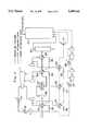
- FIG. 1 is a block diagram generally showing the structure of a compressor drive system for a natural gas liquefaction plant to which the present invention is applied;
- FIG. 2 is a flow chart showing the liquefaction process carried out in the natural gas liquefaction plant.
- FIG. 1 generally illustrates a compressor drive system for a natural gas liquefaction plant to which the present invention is applied.
- This compressor drive system is designed to drive a propane compressor 1 and a pair of serially connected mixed refrigerant compressors 2 and 3 for pressurizing two different refrigerants (having different compositions) each circulating in an independent dosed loop.
- the propane compressor 1 is connected to a gas turbine 4 and a synchronous motor 5, and the mixed refrigerant compressors 2 and 3 are connected to a gas turbine 6 and a synchronous motor 7.
- the propane compressor 1 pressurizes propane which serves as the refrigerant for a first refrigeration loop as described hereinafter, and is driven by the single-shaft gas turbine 4.
- the mixed refrigerant compressors 2 and 3 pressurize a mixed refrigerant, consisting of a mixture of nitrogen, methane, ethane and propane, serving as the refrigerant for a second refrigeration loop, in two stages. These mixed refrigerant compressors 2 and 3 are jointly driven by the common gas turbine 6.
- the synchronous motors 5 and 7 are directly connected to a main power line 9 via switches S1 and S2, and are connected the main power line 9 also via a frequency converter 10, a switch S3 connected to the input end of the frequency converter 10, and switches S4 and S5 connected to the output end of the frequency converter 10. These synchronous motors 5 and 7 are used also as AC generators. Synchronous signal power sources 11 and 12 are provided for detecting the phase conditions of the power line 9 and the synchronous motors 5 and 7, and output lines from these synchronous signal power sources 11 and 12 are connected to a synchronous signal detector 13.
- the switches S1, S2 and S5 are kept open, the switches S3 and S4 are dosed.
- the synchronous motor 5 is synchronized in a low frequency range by tuning the frequency converter 10, and the frequency is progressively increased in synchronism with the corresponding increase in the rotational speed of the propane compressor 1 and the gas turbine 4.
- the electric power generated by the in-plant power station 8 is supplied to the synchronous motor 5 via the main power line 9 and the frequency converter 10, and the output torque produced by the synchronous motor 5 supplements the output torque of the gas turbine 4 during the startup until the gas turbine 4 is smoothly accelerated to the rotational speed from which the gas turbine 4 can accelerate itself.
- the synchronous motor 5 is driven by the gas turbine 4 jointly with the propane compressor 1.
- the phase condition of this freely rotating synchronous motor 5 is transmitted from the synchronous signal power source 12 to the synchronous signal detector 13.
- the gas turbine 4 is finely adjusted until the phase condition of the synchronous motor 5 matches with the phase condition of the main power line 9, and, then, the switch S1 is closed so as to directly connect the synchronous motor 5 to the main electric power line 9.
- the power consumed by electric facilities 14, such as electric motors for driving pumps, small compressors, blowers and other auxiliary equipment, connected to the main power line 9 is supplemented by the synchronous motor 5 which can convert any excess power produced by the gas turbine 4 into electric power.
- the gas turbine 4 is allowed to operate at a full output condition or, in other words, at a high efficiency operating condition while the burden of the in-plant power station 8 is substantially reduced.
- the synchronous motor 7 it can be also converted into electric power by the synchronous motor 7 in a similar fashion.
- a possible case of insufficient power output from the gas turbine 4 can arise during summer when the power requirement of the propane compressor 1 increases due to a rise in the temperature of the sea water for cooling and the power output from the gas turbine 4 decreases due to the rise in the ambient temperature because the propane compressor 1 and the gas turbine 4 are designed for the spring and fall seasons.
- any insufficiency of torque output from the gas turbine 4 can be appropriately supplemented not only at the time of startup but also during steady state operation, and the increase in the power requirement of the compressor 1 and the decrease in the power output of the gas turbine 4 can be accommodated in a flexible fashion.
- the same arrangement can be made with the gas turbine 6 and the synchronous motor 7 for the mixed cooling compressors 2 and 3, and any insufficiency of the torque output of the gas turbine 6 during steady state operation can be supplemented by the synchronous motor 7.
- the propane compressor 1 then requires a drive unit capable of producing 45 MW of power, and the mixed refrigerant compressors 2 and 3 require a drive unit capable of producing 71 MW of power.
- the gas turbines 4 and 6 having identical specifications and an identical power output of 72 MW are used for driving the propane compressor 1 and the mixed refrigerant compressors 2 and 3 by taking into account the power requirement of the mixed refrigerant compressors 2 and 3. By doing so, it is now necessary to prepare only one set of spare parts for major components such as a rotor and bearings as the common back-up for the two identical gas turbines.
- the synchronous motor 5 associated with the propane compressor 1 thus has a maximum excess power of 27 MW.
- This excess electric power is supplied to the in-plant electric facilities (electricity users) 14 via the switch S1 and the main power line 9, and reduces the burden on the in-plant power station 8.
- the excess electric power may be supplied to the synchronous motor 7 associated with the mixed refrigerant compressors 2 and 3 via the main electric power line 9 and the switch S2, and supplement the torque output of the gas turbine 6.
- a natural gas liquefaction plant of this size typically requires approximately 25 MW of electric power for electric power users 14 in the plant, and this amount of electric power can be sufficiently supplied by the excess power generated by the synchronous motor 5 associated with the propane compressor 1. Therefore, the in-plant power station 8 is not required to be capable of producing any more than 10 MW of electric power which is required for starting the propane compressor 1 and the mixed refrigerant compressors 2 and 3.
- the propane refrigerant pressurized by the propane compressor 1 circulates in a first refrigeration loop indicated by fine solid lines in FIG. 2, and the mixed refrigerant pressurized by the mixed refrigerant compressors 2 and 3 circulates in a second refrigeration loop indicated by broken lines in FIG. 2.
- the purified natural gas at the pressure of approximately 50 bar is cooled to 21° C. in a heat exchanger 21 using a high pressure propane (at the pressure of 7.7 bar, and the temperature of 17° C.), and most of the moisture content thereof is condensed and separated in a drum 22.
- a dryer 23 then further removes moisture from the natural gas to a level below 1 ppm.
- the thus dried natural gas is cooled to -10° C. in a heat exchanger 24 using a medium pressure propane (at the pressure of 3.2 bar, and the temperature of -13° C.), and then cooled to -30° C.
- a heat exchanger 25 using a low pressure propane (at the pressure of 1.3 bar, and the temperature of -37° C).
- propane at the pressure of 1.3 bar, and the temperature of -37° C.
- the natural gas is then conducted to a scrub column 26 to separate a heavier fraction therefrom.
- the natural gas is cooled to -162° C. in a main heat exchanger 27 using the mixed refrigerant of the second refrigeration loop, and the thus liquefied natural gas is forwarded to an LNG tank.
- the propane refrigerant collected from the heat exchangers 21, 24 and 25 and chillers 28 to 30 is pressurized to 16 bar in the propane compressor 1, and is cooled to 47° C. which is close to the condensation temperature thereof by exchanging heat with cooling water in a desuperheater 31 before it is further cooled and completely condensed by exchanging heat with cooling water in a condenser 32.
- the condensed propane refrigerant is depressurized to prescribed pressure levels by expansion valves 33 to 38, and is then forwarded to the heat exchangers 21, 24 and 25 and the chillers 28 to 30.
- the mixed refrigerant which has exchanged heat with the natural gas in the main heat exchanger 27 is compressed by the mixed cooling compressors 2 and 3 in two stages, and is then cooled to 45° C. by cooling water in an intercooler 39 and an aftercooler 40.
- the thus compressed mixed refrigerant then sequentially exchanges heat in the chillers 28 to 30 with the propane refrigerant which is depressurized in three stages, and finally cooled to -35° C. thereby causing partial condensation thereof.
- two gas turbines are used for driving the compressors for pressurizing two refrigerants, but the present invention is not limited by this embodiment, and can be applied equally to the cases involving more than two refrigerants and/or using more than two gas turbines.
- the electric motors serving also as AC generators consisted of synchronous motors, but the present invention is not limited by this embodiment, and the present invention can be substantially equally applied to the cases where induction motors and other motors preferably controlled by inverters are used.
- the present invention it is possible to reduce the fuel consumption by efficient operation of the gas turbines, and a substantial gain can be achieved in reducing the operation cost. Additionally, a substantial gain can be achieved by reducing the investment cost of the plant by allowing the reduction in the capacity of the in-plant power station to be made, combined with a substantial saving in the cost for preparing a stand-by unit of the power station and spare parts of the gas turbines. Furthermore, it is made possible to fiexibly take measures against seasonal changes in the power requirement of the compressors and the power output of the gas turbines, and the freedom in the plant design can be enhanced. It is possible to maximize the production capacity of the liquefaction plant for a given make of the gas turbines.
- the present invention has been described in terms of a specific embodiment, it is possible to modify and alter details thereof without departing from the spirit of the present invention.
- the gas turbines used in the present invention are not limited to the single-shaft gas turbines described above, but may consist of gas turbines having double or triple shafts.
- the entire plant consisted of a single system, but it is possible to arrange a plurality of such systems in parallel, and use other combinations of gas turbines.
Abstract
Description
Claims (4)
Applications Claiming Priority (2)
| Application Number | Priority Date | Filing Date | Title |
|---|---|---|---|
| JP7-048994 | 1995-02-14 | ||
| JP04899495A JP3563143B2 (en) | 1995-02-14 | 1995-02-14 | Compressor drive of natural gas liquefaction plant |
Publications (1)
| Publication Number | Publication Date |
|---|---|
| US5689141A true US5689141A (en) | 1997-11-18 |
Family
ID=12818775
Family Applications (1)
| Application Number | Title | Priority Date | Filing Date |
|---|---|---|---|
| US08/458,322 Expired - Lifetime US5689141A (en) | 1995-02-14 | 1995-06-06 | Compressor drive system for a natural gas liquefaction plant having an electric motor generator to feed excess power to the main power source |
Country Status (2)
| Country | Link |
|---|---|
| US (1) | US5689141A (en) |
| JP (1) | JP3563143B2 (en) |
Cited By (50)
| Publication number | Priority date | Publication date | Assignee | Title |
|---|---|---|---|---|
| WO2001040725A1 (en) * | 1999-12-01 | 2001-06-07 | Shell Internationale Research Maatschappij B.V. | Offshore plant for liquefying natural gas |
| US6282910B1 (en) * | 2000-06-21 | 2001-09-04 | American Standard International Inc. | Indoor blower variable speed drive for reduced airflow |
| US6360535B1 (en) | 2000-10-11 | 2002-03-26 | Ingersoll-Rand Company | System and method for recovering energy from an air compressor |
| EP1253388A1 (en) * | 2001-04-23 | 2002-10-30 | Linde Aktiengesellschaft | Process and apparatus for liquefaction of natural gas |
| US6504261B2 (en) * | 2000-05-16 | 2003-01-07 | General Electric Company | Synchronous generator having auxiliary power windings and variable frequency power source and method for use |
| US20030052485A1 (en) * | 2001-09-06 | 2003-03-20 | Darrell Poteet | Redundant prime mover system |
| WO2003025370A1 (en) * | 2001-09-21 | 2003-03-27 | Turbec Ab | Power distribution system and a method for control of a power distribution system |
| US20030060907A1 (en) * | 2001-09-06 | 2003-03-27 | Darrell Poteet | Control system for a redundant prime mover system |
| US6640586B1 (en) | 2002-11-01 | 2003-11-04 | Conocophillips Company | Motor driven compressor system for natural gas liquefaction |
| US6691531B1 (en) | 2002-10-07 | 2004-02-17 | Conocophillips Company | Driver and compressor system for natural gas liquefaction |
| WO2004031669A1 (en) * | 2002-09-30 | 2004-04-15 | Bp Corporation North America Inc. | Reduced carbon dioxide emission system and method for providing power for refrigerant compression and electrical power for a light hydrocarbon gas liquefaction process |
| US20040089021A1 (en) * | 2002-11-13 | 2004-05-13 | Patrick Le Bot | Integrated air separation process and apparatus |
| US20040098142A1 (en) * | 2000-10-09 | 2004-05-20 | Energy Transfer Group, Llc | Arbitrage control system for two or more available power sources |
| US20040129020A1 (en) * | 2002-09-30 | 2004-07-08 | Richard Jones | All electric LNG system and process |
| US20040134196A1 (en) * | 2002-09-30 | 2004-07-15 | Richard Jones | Reduced carbon dioxide emission system and method for providing power for refrigerant compression and electrical power for a light hydrocarbon gas liquefaction process using cooled air injection to the turbines |
| US20050022552A1 (en) * | 2003-07-30 | 2005-02-03 | Lucas Clifford E. | Utilization of bogdown of single-shaft gas turbines to minimize relief flows in baseload LNG plants |
| US20050056021A1 (en) * | 2003-09-12 | 2005-03-17 | Mes International, Inc. | Multi-spool turbogenerator system and control method |
| WO2005111522A1 (en) * | 2004-05-13 | 2005-11-24 | Linde Aktiengesellschaft | Method and device for liquefying a hydrocarbon-enriched flow |
| WO2005047789A3 (en) * | 2003-11-06 | 2006-07-13 | Exxonmobil Upstream Res Co | Method for efficient, nonsynchronous lng production |
| US20070113584A1 (en) * | 2005-11-18 | 2007-05-24 | Eaton Anthony P | Optimized LNG system with liquid expander |
| WO2008033033A2 (en) | 2006-09-12 | 2008-03-20 | Aker Engineering & Technology As | Method and system for start and operation of an electrically driven load |
| EP1937949A2 (en) * | 2005-09-14 | 2008-07-02 | Conocophillips Company | Rotation coupling employing torque converter and synchronization motor |
| EP1942279A1 (en) | 2007-01-08 | 2008-07-09 | Siemens Aktiengesellschaft | Method for operating a compressor assembly and compressor assembly |
| US20080170948A1 (en) * | 2007-01-11 | 2008-07-17 | Conocophillips Company | Multi-stage compressor/driver system and method of operation |
| US20090054191A1 (en) * | 2006-03-06 | 2009-02-26 | Holt Christopher G | Dual End Gear Fluid Drive Starter |
| US20090183524A1 (en) * | 2006-06-08 | 2009-07-23 | Daikin Industries, Ltd. | Refrigerating Apparatus |
| US20090260367A1 (en) * | 2005-12-23 | 2009-10-22 | Martin William L | Multi-Compressor String With Multiple Variable Speed Fluid Drives |
| US20100013326A1 (en) * | 2007-02-14 | 2010-01-21 | Alstom Technology Ltd | Power station having a consumer and method for its operation |
| US20100031670A1 (en) * | 2007-02-14 | 2010-02-11 | Alstom Technology Ltd | Power station and method for its operation |
| US20100032964A1 (en) * | 2007-02-14 | 2010-02-11 | Alstom Technology Ltd | Method for operating a power plant |
| US20100031667A1 (en) * | 2007-02-14 | 2010-02-11 | Alstom Technology Ltd | Method for operating a power plant |
| WO2010054434A1 (en) * | 2008-11-17 | 2010-05-20 | Woodside Energy Limited | Power matched mixed refrigerant compression circuit |
| US20100242495A1 (en) * | 2009-03-27 | 2010-09-30 | Solar Turbines Incorporated | Hybrid gas turbine engine - electric motor/generator drive system |
| US20100275644A1 (en) * | 2008-01-23 | 2010-11-04 | Tomomi Koganezawa | Natural gas liquefaction plant and motive power supply equipment for same |
| US20100319356A1 (en) * | 2007-12-27 | 2010-12-23 | Kazuhiro Takeda | Control apparatus and control method for compressor |
| US20110148123A1 (en) * | 2008-08-25 | 2011-06-23 | Rheinisch-Westfalish- Technische Hochschule Aachen | Zero-Emission Power Plant |
| US20120090351A1 (en) * | 2009-05-18 | 2012-04-19 | Carolus Antonius Cornelis Van De Lisdonk | Method of cooling a hydrocarbon stream and apparatus therefor |
| WO2013010016A1 (en) * | 2011-07-14 | 2013-01-17 | Jackson Keneth A | Natural gas pressure regulator that produces electric energy |
| US20130119666A1 (en) * | 2010-07-30 | 2013-05-16 | Christopher G. Holt | Systems and methods for using multiple cryogenic hydraulic turbines |
| US8853878B1 (en) | 2013-05-14 | 2014-10-07 | Solar Turbines Inc. | Gas turbine engine with multiple load outputs |
| ITFI20130130A1 (en) * | 2013-05-31 | 2014-12-01 | Nuovo Pignone Srl | "GAS TURBINES IN MECHANICAL DRIVE APPLICATIONS AND OPERATING METHODS" |
| US20140360227A1 (en) * | 2011-12-21 | 2014-12-11 | L'air Liquide, Societe Anonyme Pour L'etude Et I'exploitation Des Procedes Georges Claude | Method For Producing One Or More Air Separation Apparatuses, And Equipment For Air Separation By Cryogenic Distillation |
| US9284964B2 (en) | 2010-05-21 | 2016-03-15 | Exxonmobil Upstream Research Company | Parallel dynamic compressor arrangement and methods related thereto |
| US20160245112A1 (en) * | 2015-02-24 | 2016-08-25 | General Electric Technology Gmbh | Method for operating a gas turbine arrangement |
| US9746234B2 (en) | 2008-09-19 | 2017-08-29 | Woodside Energy Ltd | Mixed refrigerant compression circuit |
| WO2018212830A1 (en) | 2017-05-16 | 2018-11-22 | Exxonmobil Upstream Research Company | Method and system for efficient nonsynchronous lng production using large scale multi-shaft gas tusbines |
| US10174630B2 (en) | 2012-11-08 | 2019-01-08 | Nuovo Pignone Srl | Gas turbine in mechanical drive applications and operating methods |
| WO2019040154A1 (en) | 2017-08-24 | 2019-02-28 | Exxonmobil Upstream Research Company | Method and system for lng production using standardized multi-shaft gas turbines, compressors and refrigerant systems |
| US10781752B2 (en) | 2016-03-23 | 2020-09-22 | Chiyoda Corporation | Inlet air cooling system and inlet air cooling method for gas turbine |
| US11022042B2 (en) | 2016-08-29 | 2021-06-01 | Rolls-Royce North American Technologies Inc. | Aircraft having a gas turbine generator with power assist |
Families Citing this family (4)
| Publication number | Priority date | Publication date | Assignee | Title |
|---|---|---|---|---|
| EP2044376A2 (en) * | 2006-07-21 | 2009-04-08 | Shell Internationale Research Maatschappij B.V. | Method and apparatus for liquefying a hydrocarbon stream |
| WO2008139527A1 (en) * | 2007-04-27 | 2008-11-20 | Hitachi, Ltd. | Power supply facility for natural gas liquefaction plant, system and method for control of the power supply facility, and natural gas liquefaction plant |
| JP2011506895A (en) * | 2007-12-07 | 2011-03-03 | ドレッサー ランド カンパニー | Compressor apparatus and method for gas liquefaction system |
| WO2019017421A1 (en) * | 2017-07-19 | 2019-01-24 | 千代田化工建設株式会社 | Lng production output prediction system |
Citations (7)
| Publication number | Priority date | Publication date | Assignee | Title |
|---|---|---|---|---|
| US3764815A (en) * | 1971-03-06 | 1973-10-09 | Siemens Ag | Start-up converter |
| US4036028A (en) * | 1974-11-22 | 1977-07-19 | Sulzer Brothers Limited | Process and apparatus for evaporating and heating liquified natural gas |
| US4069424A (en) * | 1976-05-10 | 1978-01-17 | Turbodyne Corporation (Gas Turbine Div.) | Shaft turning parking bus for multiple unit installations utilizing a single motorized generator control system |
| US4093869A (en) * | 1976-04-13 | 1978-06-06 | Westinghouse Electric Corp. | Quadrature axis field brushless exciter |
| US4359871A (en) * | 1978-12-01 | 1982-11-23 | Linde Aktiengesellschaft | Method of and apparatus for the cooling of natural gas |
| US4566885A (en) * | 1983-11-18 | 1986-01-28 | Shell Oil Company | Gas liquefaction process |
| US5365740A (en) * | 1992-07-24 | 1994-11-22 | Chiyoda Corporation | Refrigeration system for a natural gas liquefaction process |
-
1995
- 1995-02-14 JP JP04899495A patent/JP3563143B2/en not_active Expired - Lifetime
- 1995-06-06 US US08/458,322 patent/US5689141A/en not_active Expired - Lifetime
Patent Citations (7)
| Publication number | Priority date | Publication date | Assignee | Title |
|---|---|---|---|---|
| US3764815A (en) * | 1971-03-06 | 1973-10-09 | Siemens Ag | Start-up converter |
| US4036028A (en) * | 1974-11-22 | 1977-07-19 | Sulzer Brothers Limited | Process and apparatus for evaporating and heating liquified natural gas |
| US4093869A (en) * | 1976-04-13 | 1978-06-06 | Westinghouse Electric Corp. | Quadrature axis field brushless exciter |
| US4069424A (en) * | 1976-05-10 | 1978-01-17 | Turbodyne Corporation (Gas Turbine Div.) | Shaft turning parking bus for multiple unit installations utilizing a single motorized generator control system |
| US4359871A (en) * | 1978-12-01 | 1982-11-23 | Linde Aktiengesellschaft | Method of and apparatus for the cooling of natural gas |
| US4566885A (en) * | 1983-11-18 | 1986-01-28 | Shell Oil Company | Gas liquefaction process |
| US5365740A (en) * | 1992-07-24 | 1994-11-22 | Chiyoda Corporation | Refrigeration system for a natural gas liquefaction process |
Cited By (105)
| Publication number | Priority date | Publication date | Assignee | Title |
|---|---|---|---|---|
| US6658891B2 (en) * | 1999-12-01 | 2003-12-09 | Shell Research Limited | Offshore plant for liquefying natural gas |
| AP1430A (en) * | 1999-12-01 | 2005-06-13 | Shell Int Research | Offshore plant for liquefying natural gas. |
| KR100758501B1 (en) * | 1999-12-01 | 2007-09-13 | 쉘 인터내셔날 리서치 마챠피즈 비.브이. | Offshore plant for liquefying natural gas |
| AU763051B2 (en) * | 1999-12-01 | 2003-07-10 | Shell Internationale Research Maatschappij B.V. | Offshore plant for liquefying natural gas |
| WO2001040725A1 (en) * | 1999-12-01 | 2001-06-07 | Shell Internationale Research Maatschappij B.V. | Offshore plant for liquefying natural gas |
| US6504261B2 (en) * | 2000-05-16 | 2003-01-07 | General Electric Company | Synchronous generator having auxiliary power windings and variable frequency power source and method for use |
| US6282910B1 (en) * | 2000-06-21 | 2001-09-04 | American Standard International Inc. | Indoor blower variable speed drive for reduced airflow |
| US20040098142A1 (en) * | 2000-10-09 | 2004-05-20 | Energy Transfer Group, Llc | Arbitrage control system for two or more available power sources |
| US9605591B2 (en) | 2000-10-09 | 2017-03-28 | Energy Transfer Group, L.L.C. | Arbitrage control system for two or more available power sources |
| US6360535B1 (en) | 2000-10-11 | 2002-03-26 | Ingersoll-Rand Company | System and method for recovering energy from an air compressor |
| EP1197662A2 (en) | 2000-10-11 | 2002-04-17 | Ingersoll-Rand Company | System and method for recovering energy from an air compressor |
| EP1253388A1 (en) * | 2001-04-23 | 2002-10-30 | Linde Aktiengesellschaft | Process and apparatus for liquefaction of natural gas |
| US20030060907A1 (en) * | 2001-09-06 | 2003-03-27 | Darrell Poteet | Control system for a redundant prime mover system |
| US7042111B2 (en) | 2001-09-06 | 2006-05-09 | Enevsy Transfer Group, Llc | System, method and apparatus for a redundant prime mover system |
| US20030052485A1 (en) * | 2001-09-06 | 2003-03-20 | Darrell Poteet | Redundant prime mover system |
| US6750557B2 (en) * | 2001-09-06 | 2004-06-15 | Energy Transfer Group, L.L.C. | Redundant prime mover system |
| US6912451B2 (en) | 2001-09-06 | 2005-06-28 | Energy Transfer Group, Llc | Control system for a redundant prime mover system |
| US20050116473A1 (en) * | 2001-09-06 | 2005-06-02 | Energy Transfer Group, Llc | System, method and apparatus for a redundant prime mover system |
| WO2003025370A1 (en) * | 2001-09-21 | 2003-03-27 | Turbec Ab | Power distribution system and a method for control of a power distribution system |
| US7131272B2 (en) | 2002-09-30 | 2006-11-07 | Bp Corporation North America Inc. | Reduced carbon dioxide emission system and method for providing power for refrigerant compression and electrical power for a light hydrocarbon gas liquefaction process using cooled air injection to the turbines |
| US7114351B2 (en) * | 2002-09-30 | 2006-10-03 | Bp Corporation North America Inc. | All electric LNG system and process |
| US20040134196A1 (en) * | 2002-09-30 | 2004-07-15 | Richard Jones | Reduced carbon dioxide emission system and method for providing power for refrigerant compression and electrical power for a light hydrocarbon gas liquefaction process using cooled air injection to the turbines |
| US20040129020A1 (en) * | 2002-09-30 | 2004-07-08 | Richard Jones | All electric LNG system and process |
| US20040129019A1 (en) * | 2002-09-30 | 2004-07-08 | Richard Jones | Reduced carbon dioxide emission system and method for providing power for refrigerant compression and electrical power for a light hydrocarbon gas liquefaction process |
| WO2004031669A1 (en) * | 2002-09-30 | 2004-04-15 | Bp Corporation North America Inc. | Reduced carbon dioxide emission system and method for providing power for refrigerant compression and electrical power for a light hydrocarbon gas liquefaction process |
| US7243510B2 (en) | 2002-09-30 | 2007-07-17 | Bp Corporation North America Inc. | Reduced carbon dioxide emission system and method for providing power for refrigerant compression and electrical power for a light hydrocarbon gas liquefaction process |
| US6691531B1 (en) | 2002-10-07 | 2004-02-17 | Conocophillips Company | Driver and compressor system for natural gas liquefaction |
| CN1703606B (en) * | 2002-10-07 | 2010-10-27 | 科诺科菲利浦公司 | Improved driver and compressor system for natural gas liquefaction |
| US6640586B1 (en) | 2002-11-01 | 2003-11-04 | Conocophillips Company | Motor driven compressor system for natural gas liquefaction |
| US6915661B2 (en) * | 2002-11-13 | 2005-07-12 | L'air Liquide - Societe Anonyme A'directoire Et Conseil De Surveillance Pour L'etude Et L'exploitation Des Procedes George Claude | Integrated air separation process and apparatus |
| US20040089021A1 (en) * | 2002-11-13 | 2004-05-13 | Patrick Le Bot | Integrated air separation process and apparatus |
| US7069733B2 (en) * | 2003-07-30 | 2006-07-04 | Air Products And Chemicals, Inc. | Utilization of bogdown of single-shaft gas turbines to minimize relief flows in baseload LNG plants |
| US20050022552A1 (en) * | 2003-07-30 | 2005-02-03 | Lucas Clifford E. | Utilization of bogdown of single-shaft gas turbines to minimize relief flows in baseload LNG plants |
| US6931856B2 (en) | 2003-09-12 | 2005-08-23 | Mes International, Inc. | Multi-spool turbogenerator system and control method |
| WO2005028832A1 (en) * | 2003-09-12 | 2005-03-31 | Mes International, Inc. | Multi-spool turbogenerator system and control method |
| US20050056021A1 (en) * | 2003-09-12 | 2005-03-17 | Mes International, Inc. | Multi-spool turbogenerator system and control method |
| WO2005047789A3 (en) * | 2003-11-06 | 2006-07-13 | Exxonmobil Upstream Res Co | Method for efficient, nonsynchronous lng production |
| US7526926B2 (en) * | 2003-11-06 | 2009-05-05 | Exxonmobil Upstream Research Company | Method for efficient nonsynchronous LNG production |
| US20060283206A1 (en) * | 2003-11-06 | 2006-12-21 | Rasmussen Peter C | Method for efficient nonsynchronous lng production |
| CN1864042B (en) * | 2003-11-06 | 2010-07-14 | 埃克森美孚上游研究公司 | Method for efficient nonsynchronous LNG production |
| AU2004289969B2 (en) * | 2003-11-06 | 2009-08-27 | Exxonmobil Upstream Research Company | Method for efficient, nonsynchronous LNG production |
| WO2005111522A1 (en) * | 2004-05-13 | 2005-11-24 | Linde Aktiengesellschaft | Method and device for liquefying a hydrocarbon-enriched flow |
| EP1937949A4 (en) * | 2005-09-14 | 2015-04-22 | Conocophillips Co | Rotation coupling employing torque converter and synchronization motor |
| EP1937949A2 (en) * | 2005-09-14 | 2008-07-02 | Conocophillips Company | Rotation coupling employing torque converter and synchronization motor |
| US7415840B2 (en) * | 2005-11-18 | 2008-08-26 | Conocophillips Company | Optimized LNG system with liquid expander |
| US20070113584A1 (en) * | 2005-11-18 | 2007-05-24 | Eaton Anthony P | Optimized LNG system with liquid expander |
| US20090260367A1 (en) * | 2005-12-23 | 2009-10-22 | Martin William L | Multi-Compressor String With Multiple Variable Speed Fluid Drives |
| US8517693B2 (en) * | 2005-12-23 | 2013-08-27 | Exxonmobil Upstream Research Company | Multi-compressor string with multiple variable speed fluid drives |
| US20090054191A1 (en) * | 2006-03-06 | 2009-02-26 | Holt Christopher G | Dual End Gear Fluid Drive Starter |
| US8381617B2 (en) | 2006-03-06 | 2013-02-26 | Exxonmobil Upstream Research Company | Dual end gear fluid drive starter |
| US20090183524A1 (en) * | 2006-06-08 | 2009-07-23 | Daikin Industries, Ltd. | Refrigerating Apparatus |
| EP2070185A2 (en) * | 2006-09-12 | 2009-06-17 | Aker Engineering & Technology AS | Method and system for start and operation of an electrically driven load |
| US20120313372A1 (en) * | 2006-09-12 | 2012-12-13 | Aker Engineering & Technology As | Method and system for start and operation of an electrically driven load |
| US20100019717A1 (en) * | 2006-09-12 | 2010-01-28 | Aker Engineering & Technology As | Method and system for start and operation of an electrically driven load |
| US8269449B2 (en) | 2006-09-12 | 2012-09-18 | Acker Engineering & Technology AS | Method and system for start and operation of an electrically driven load |
| WO2008033033A2 (en) | 2006-09-12 | 2008-03-20 | Aker Engineering & Technology As | Method and system for start and operation of an electrically driven load |
| US8872467B2 (en) * | 2006-09-12 | 2014-10-28 | Aker Engineering & Technology As | Method and system for start and operation of an electrically driven load |
| EP2070185A4 (en) * | 2006-09-12 | 2014-04-02 | Aker Engineering & Technology | Method and system for start and operation of an electrically driven load |
| WO2008083902A1 (en) * | 2007-01-08 | 2008-07-17 | Siemens Aktiengesellschaft | Method for operating a compressor arrangement, and a compressor arrangement |
| CN101663488B (en) * | 2007-01-08 | 2012-07-04 | 西门子公司 | Method for operating a compressor arrangement, and a compressor arrangement |
| US20100215512A1 (en) * | 2007-01-08 | 2010-08-26 | Ulrich Schwulera | Method for operating a compressor arrangement, and a compressor arrangement |
| EP1942279A1 (en) | 2007-01-08 | 2008-07-09 | Siemens Aktiengesellschaft | Method for operating a compressor assembly and compressor assembly |
| US8591199B2 (en) | 2007-01-11 | 2013-11-26 | Conocophillips Company | Multi-stage compressor/driver system and method of operation |
| US20080170948A1 (en) * | 2007-01-11 | 2008-07-17 | Conocophillips Company | Multi-stage compressor/driver system and method of operation |
| US20100031670A1 (en) * | 2007-02-14 | 2010-02-11 | Alstom Technology Ltd | Power station and method for its operation |
| US20100013326A1 (en) * | 2007-02-14 | 2010-01-21 | Alstom Technology Ltd | Power station having a consumer and method for its operation |
| US20100031667A1 (en) * | 2007-02-14 | 2010-02-11 | Alstom Technology Ltd | Method for operating a power plant |
| US7944094B2 (en) | 2007-02-14 | 2011-05-17 | Alstom Technology Ltd. | Power station having a consumer and method for its operation |
| US9605556B2 (en) | 2007-02-14 | 2017-03-28 | General Electric Company | Power station and method for its operation |
| US8373295B2 (en) | 2007-02-14 | 2013-02-12 | Alstom Technology Ltd | Method for operating a power plant |
| US8796874B2 (en) | 2007-02-14 | 2014-08-05 | Alstom Technology Ltd | Method for operating a power plant |
| US20100032964A1 (en) * | 2007-02-14 | 2010-02-11 | Alstom Technology Ltd | Method for operating a power plant |
| US8695321B2 (en) | 2007-12-27 | 2014-04-15 | Mitsubishi Heavy Industries, Ltd. | Gas turbine control apparatus and control method for generating an electric motor torque instruction based on the detected exhaust gas temperature |
| US20100319356A1 (en) * | 2007-12-27 | 2010-12-23 | Kazuhiro Takeda | Control apparatus and control method for compressor |
| US20100275644A1 (en) * | 2008-01-23 | 2010-11-04 | Tomomi Koganezawa | Natural gas liquefaction plant and motive power supply equipment for same |
| US8438874B2 (en) * | 2008-01-23 | 2013-05-14 | Hitachi, Ltd. | Natural gas liquefaction plant and motive power supply equipment for same |
| US20110148123A1 (en) * | 2008-08-25 | 2011-06-23 | Rheinisch-Westfalish- Technische Hochschule Aachen | Zero-Emission Power Plant |
| US9746234B2 (en) | 2008-09-19 | 2017-08-29 | Woodside Energy Ltd | Mixed refrigerant compression circuit |
| WO2010054434A1 (en) * | 2008-11-17 | 2010-05-20 | Woodside Energy Limited | Power matched mixed refrigerant compression circuit |
| US8468835B2 (en) | 2009-03-27 | 2013-06-25 | Solar Turbines Inc. | Hybrid gas turbine engine—electric motor/generator drive system |
| US20100242495A1 (en) * | 2009-03-27 | 2010-09-30 | Solar Turbines Incorporated | Hybrid gas turbine engine - electric motor/generator drive system |
| US20120090351A1 (en) * | 2009-05-18 | 2012-04-19 | Carolus Antonius Cornelis Van De Lisdonk | Method of cooling a hydrocarbon stream and apparatus therefor |
| US9284964B2 (en) | 2010-05-21 | 2016-03-15 | Exxonmobil Upstream Research Company | Parallel dynamic compressor arrangement and methods related thereto |
| US20130119666A1 (en) * | 2010-07-30 | 2013-05-16 | Christopher G. Holt | Systems and methods for using multiple cryogenic hydraulic turbines |
| US11644234B2 (en) | 2010-07-30 | 2023-05-09 | ExxonMobil Technology and Enginering Company | Systems and methods for using multiple cryogenic hydraulic turbines |
| US10648729B2 (en) | 2010-07-30 | 2020-05-12 | Exxonmobil Upstream Research Company | Systems and methods for using multiple cryogenic hydraulic turbines |
| WO2013010016A1 (en) * | 2011-07-14 | 2013-01-17 | Jackson Keneth A | Natural gas pressure regulator that produces electric energy |
| US20140360227A1 (en) * | 2011-12-21 | 2014-12-11 | L'air Liquide, Societe Anonyme Pour L'etude Et I'exploitation Des Procedes Georges Claude | Method For Producing One Or More Air Separation Apparatuses, And Equipment For Air Separation By Cryogenic Distillation |
| US10174630B2 (en) | 2012-11-08 | 2019-01-08 | Nuovo Pignone Srl | Gas turbine in mechanical drive applications and operating methods |
| US8853878B1 (en) | 2013-05-14 | 2014-10-07 | Solar Turbines Inc. | Gas turbine engine with multiple load outputs |
| ITFI20130130A1 (en) * | 2013-05-31 | 2014-12-01 | Nuovo Pignone Srl | "GAS TURBINES IN MECHANICAL DRIVE APPLICATIONS AND OPERATING METHODS" |
| CN105579690B (en) * | 2013-05-31 | 2017-10-24 | 诺沃皮尼奥内股份有限公司 | Gas turbine and operating method in Mechanical Driven application |
| US9876412B2 (en) | 2013-05-31 | 2018-01-23 | Nuovo Pignone Srl | Gas turbines in mechanical drive applications and operating methods |
| WO2014191543A1 (en) * | 2013-05-31 | 2014-12-04 | Nuovo Pignone Srl | Gas turbines in mechanical drive applications and operating methods |
| CN105579690A (en) * | 2013-05-31 | 2016-05-11 | 诺沃皮尼奥内股份有限公司 | Gas turbines in mechanical drive applications and operating methods |
| RU2703189C2 (en) * | 2013-05-31 | 2019-10-16 | Нуово Пиньоне СРЛ | Drive unit (embodiments) and drive unit control method |
| US10100661B2 (en) * | 2015-02-24 | 2018-10-16 | Ansaldo Energia Switzerland AG | Method for operating a gas turbine arrangement |
| US20160245112A1 (en) * | 2015-02-24 | 2016-08-25 | General Electric Technology Gmbh | Method for operating a gas turbine arrangement |
| US10781752B2 (en) | 2016-03-23 | 2020-09-22 | Chiyoda Corporation | Inlet air cooling system and inlet air cooling method for gas turbine |
| US11022042B2 (en) | 2016-08-29 | 2021-06-01 | Rolls-Royce North American Technologies Inc. | Aircraft having a gas turbine generator with power assist |
| US11274880B2 (en) | 2017-05-16 | 2022-03-15 | Exxonmobil Upstream Research Company | Method and system for efficient nonsynchronous LNG production using large scale multi-shaft gas turbines |
| WO2018212830A1 (en) | 2017-05-16 | 2018-11-22 | Exxonmobil Upstream Research Company | Method and system for efficient nonsynchronous lng production using large scale multi-shaft gas tusbines |
| US11747081B2 (en) | 2017-05-16 | 2023-09-05 | ExxonMobil Technology and Engineering Company | Method and system for efficient nonsynchronous LNG production using large scale multi-shaft gas turbines |
| WO2019040154A1 (en) | 2017-08-24 | 2019-02-28 | Exxonmobil Upstream Research Company | Method and system for lng production using standardized multi-shaft gas turbines, compressors and refrigerant systems |
| US11105553B2 (en) | 2017-08-24 | 2021-08-31 | Exxonmobil Upstream Research Company | Method and system for LNG production using standardized multi-shaft gas turbines, compressors and refrigerant systems |
Also Published As
| Publication number | Publication date |
|---|---|
| JPH08219571A (en) | 1996-08-30 |
| JP3563143B2 (en) | 2004-09-08 |
Similar Documents
| Publication | Publication Date | Title |
|---|---|---|
| US5689141A (en) | Compressor drive system for a natural gas liquefaction plant having an electric motor generator to feed excess power to the main power source | |
| JP4819690B2 (en) | Drive system for asynchronous operation of refrigeration compressor and operation method of gas turbine output refrigeration compressor | |
| US5790972A (en) | Method and apparatus for cooling the inlet air of gas turbine and internal combustion engine prime movers | |
| US10100979B2 (en) | Liquid air as energy storage | |
| CA1231890A (en) | Method and a system for liquefying a gas, in particular a natural gas | |
| JP2011063800A (en) | All electric lng system and process | |
| GB2493791A (en) | A compressed air energy storage system | |
| KR20130031843A (en) | Boil-off gas reliquefaction device | |
| US20140260251A1 (en) | Combined Heat and Power Technology for Natural Gas Liquefaction Plants | |
| US7257965B2 (en) | Two-stage evaporation system comprising an integrated liquid supercooler and a suction vapour superheater according to frequency-controlled module technology | |
| RU2698565C2 (en) | Natural gas liquefaction method | |
| JP3208547B2 (en) | Liquefaction method of permanent gas using cold of liquefied natural gas | |
| US9608498B2 (en) | Method and device for generating electrical energy | |
| JP2004150685A (en) | Nitrogen producing equipment and turbine power generation equipment | |
| US20220082092A1 (en) | Method for Operating a Liquid Air Energy Storage | |
| US11098643B2 (en) | Method for exhaust waste energy recovery at the reciprocating gas engine-based polygeneration plant | |
| US20240003619A1 (en) | A system for producing liquefied natural gas and method | |
| JPH10205353A (en) | Method and device for driving integrated coal gasification combined cycle system | |
| RU2027124C1 (en) | Gas energy recovery set for under ground gas storage | |
| RU2049293C1 (en) | Gas energy recovery plant on underground gas storage | |
| AU2022324920A1 (en) | Power-conditioning system, power-conditioning method, and power-conditioning program | |
| GB2618053A (en) | Power generation and storage | |
| WO2020228986A1 (en) | Compressor train with combined gas turbine and steam turbine cycle | |
| MXPA06004925A (en) | Method for efficient, nonsynchronous lng production | |
| JPH09303956A (en) | Raw material air feeding method for air separating device |
Legal Events
| Date | Code | Title | Description |
|---|---|---|---|
| AS | Assignment |
Owner name: CHIYODA CORPORATION, JAPAN Free format text: ASSIGNMENT OF ASSIGNORS INTEREST;ASSIGNORS:KIKKAWA, YOSHITSUGI;YAMAMOTO, OSAMU;NAITO, YASUHIRO;AND OTHERS;REEL/FRAME:008100/0025 Effective date: 19950607 |
|
| STCF | Information on status: patent grant |
Free format text: PATENTED CASE |
|
| FEPP | Fee payment procedure |
Free format text: PAYOR NUMBER ASSIGNED (ORIGINAL EVENT CODE: ASPN); ENTITY STATUS OF PATENT OWNER: LARGE ENTITY |
|
| FPAY | Fee payment |
Year of fee payment: 4 |
|
| FPAY | Fee payment |
Year of fee payment: 8 |
|
| FPAY | Fee payment |
Year of fee payment: 12 |