US5686203A - Non-aqueous secondary battery - Google Patents
Non-aqueous secondary battery Download PDFInfo
- Publication number
- US5686203A US5686203A US08/562,223 US56222395A US5686203A US 5686203 A US5686203 A US 5686203A US 56222395 A US56222395 A US 56222395A US 5686203 A US5686203 A US 5686203A
- Authority
- US
- United States
- Prior art keywords
- compound
- secondary battery
- positive electrode
- aqueous secondary
- electrode
- Prior art date
- Legal status (The legal status is an assumption and is not a legal conclusion. Google has not performed a legal analysis and makes no representation as to the accuracy of the status listed.)
- Expired - Fee Related
Links
Images
Classifications
-
- H—ELECTRICITY
- H01—ELECTRIC ELEMENTS
- H01M—PROCESSES OR MEANS, e.g. BATTERIES, FOR THE DIRECT CONVERSION OF CHEMICAL ENERGY INTO ELECTRICAL ENERGY
- H01M4/00—Electrodes
- H01M4/02—Electrodes composed of, or comprising, active material
- H01M4/36—Selection of substances as active materials, active masses, active liquids
- H01M4/58—Selection of substances as active materials, active masses, active liquids of inorganic compounds other than oxides or hydroxides, e.g. sulfides, selenides, tellurides, halogenides or LiCoFy; of polyanionic structures, e.g. phosphates, silicates or borates
- H01M4/583—Carbonaceous material, e.g. graphite-intercalation compounds or CFx
- H01M4/587—Carbonaceous material, e.g. graphite-intercalation compounds or CFx for inserting or intercalating light metals
-
- H—ELECTRICITY
- H01—ELECTRIC ELEMENTS
- H01G—CAPACITORS; CAPACITORS, RECTIFIERS, DETECTORS, SWITCHING DEVICES OR LIGHT-SENSITIVE DEVICES, OF THE ELECTROLYTIC TYPE
- H01G11/00—Hybrid capacitors, i.e. capacitors having different positive and negative electrodes; Electric double-layer [EDL] capacitors; Processes for the manufacture thereof or of parts thereof
- H01G11/54—Electrolytes
- H01G11/56—Solid electrolytes, e.g. gels; Additives therein
-
- H—ELECTRICITY
- H01—ELECTRIC ELEMENTS
- H01M—PROCESSES OR MEANS, e.g. BATTERIES, FOR THE DIRECT CONVERSION OF CHEMICAL ENERGY INTO ELECTRICAL ENERGY
- H01M4/00—Electrodes
- H01M4/02—Electrodes composed of, or comprising, active material
- H01M4/36—Selection of substances as active materials, active masses, active liquids
- H01M4/48—Selection of substances as active materials, active masses, active liquids of inorganic oxides or hydroxides
- H01M4/485—Selection of substances as active materials, active masses, active liquids of inorganic oxides or hydroxides of mixed oxides or hydroxides for inserting or intercalating light metals, e.g. LiTi2O4 or LiTi2OxFy
-
- H—ELECTRICITY
- H01—ELECTRIC ELEMENTS
- H01M—PROCESSES OR MEANS, e.g. BATTERIES, FOR THE DIRECT CONVERSION OF CHEMICAL ENERGY INTO ELECTRICAL ENERGY
- H01M4/00—Electrodes
- H01M4/02—Electrodes composed of, or comprising, active material
- H01M4/36—Selection of substances as active materials, active masses, active liquids
- H01M4/58—Selection of substances as active materials, active masses, active liquids of inorganic compounds other than oxides or hydroxides, e.g. sulfides, selenides, tellurides, halogenides or LiCoFy; of polyanionic structures, e.g. phosphates, silicates or borates
- H01M4/581—Chalcogenides or intercalation compounds thereof
-
- H—ELECTRICITY
- H01—ELECTRIC ELEMENTS
- H01M—PROCESSES OR MEANS, e.g. BATTERIES, FOR THE DIRECT CONVERSION OF CHEMICAL ENERGY INTO ELECTRICAL ENERGY
- H01M2200/00—Safety devices for primary or secondary batteries
-
- Y—GENERAL TAGGING OF NEW TECHNOLOGICAL DEVELOPMENTS; GENERAL TAGGING OF CROSS-SECTIONAL TECHNOLOGIES SPANNING OVER SEVERAL SECTIONS OF THE IPC; TECHNICAL SUBJECTS COVERED BY FORMER USPC CROSS-REFERENCE ART COLLECTIONS [XRACs] AND DIGESTS
- Y02—TECHNOLOGIES OR APPLICATIONS FOR MITIGATION OR ADAPTATION AGAINST CLIMATE CHANGE
- Y02E—REDUCTION OF GREENHOUSE GAS [GHG] EMISSIONS, RELATED TO ENERGY GENERATION, TRANSMISSION OR DISTRIBUTION
- Y02E60/00—Enabling technologies; Technologies with a potential or indirect contribution to GHG emissions mitigation
- Y02E60/10—Energy storage using batteries
-
- Y—GENERAL TAGGING OF NEW TECHNOLOGICAL DEVELOPMENTS; GENERAL TAGGING OF CROSS-SECTIONAL TECHNOLOGIES SPANNING OVER SEVERAL SECTIONS OF THE IPC; TECHNICAL SUBJECTS COVERED BY FORMER USPC CROSS-REFERENCE ART COLLECTIONS [XRACs] AND DIGESTS
- Y02—TECHNOLOGIES OR APPLICATIONS FOR MITIGATION OR ADAPTATION AGAINST CLIMATE CHANGE
- Y02E—REDUCTION OF GREENHOUSE GAS [GHG] EMISSIONS, RELATED TO ENERGY GENERATION, TRANSMISSION OR DISTRIBUTION
- Y02E60/00—Enabling technologies; Technologies with a potential or indirect contribution to GHG emissions mitigation
- Y02E60/13—Energy storage using capacitors
Definitions
- the present invention relates to a non-aqueous secondary battery which is safe from overcharge and more specifically to a non-aqueous secondary battery which is safe from overcharge and which can ensure a high charge or discharge capacity and a high discharge voltage.
- the protective circuit often malfunctions, the current-cut off part of the current-cut off safety valve cannot hold its contact condition over a long time period and does not ensure a constant sensitivity to pressure due to the limit in precision of the production techniques. In the worst case, the battery may correspondingly be overcharged.
- J. P. KOKAI Japanese Un-Examined Patent Publication
- Sho 60-264052 discloses a battery which makes use of a calcined product of a cresol resin as an electrode material.
- the negative electrode material for high discharge voltage non-aqueous secondary battery compounds which cause a decrease in voltage through charging, for instance, naturally occurring graphite and carbonaceous compounds obtained by firing organic substances; transition metal oxides such as WO 2 , MoO 2 , Fe 2 O 3 and LiCoVO 4 ; oxides of semi-metal elements such as SnO; nonmetal oxides such as SiO; transition metal chalcogenides such as TiS 2 ; and chalcogenides of semi-metal elements such as SnS.
- transition metal oxides such as WO 2 , MoO 2 , Fe 2 O 3 and LiCoVO 4
- oxides of semi-metal elements such as SnO
- nonmetal oxides such as SiO
- transition metal chalcogenides such as TiS 2
- chalcogenides of semi-metal elements such as SnS.
- J. P. KOKAI Nos. Sho 63-121258 and Hei 5-54889 propose a method in which elements belonging to Group IIIB or IVB of the Periodic Table are incorporated into the negative electrode materials.
- Another object of the present invention is to provide a non-aqueous secondary battery capable of ensuring high charge and discharge capacities and a high discharge voltage while ensuring high safety against any overcharge.
- the inventors of this invention have conducted various studies to solve the foregoing problems associated with the conventional techniques. As a result, they have found out that these problems can effectively be solved by inserting anions into the electrode mixture for positive electrode when the battery is in an overcharge state to thus increase the internal resistance of the battery and by incorporating a specific carbonaceous substance into the electrode mixture for positive electrode and thus have completed the present invention.
- a non-aqueous secondary battery which comprises a positive electrode-active material, a negative electrode material and a non-aqueous electrolyte wherein an electrode mixture for positive electrode comprising the positive electrode-active material comprises a compound capable of inserting anions into the positive electrode-active material at a voltage of not less than 3.9 V with respect to an Li + /Li electrode.
- the insertion of anions into the positive electrode-active material when the battery is in an overcharge state results in an increase in the internal resistance of the battery and inhibition of any progress of the overcharge and ultimate termination of the overcharge.
- the electrode mixture for positive electrode further comprises at least one member selected from the group consisting of transition metals, elements belonging to Group IIIB and IVB of the Periodic Table except for C and carbides of the transition metals and the elements belonging to Group IIIB and IVB of the Periodic Table except for C.
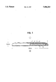
- FIG. 1 is a cross sectional view of a coin-shaped non-aqueous secondary battery according to a preferred embodiment of the present invention and prepared in Examples.
- the positive and negative electrodes used in the non-aqueous secondary battery of the present invention can be produced by applying an electrode mixture for positive or negative electrode onto a current collector.
- the electrode mixture for positive or negative electrode may comprise, in addition to the positive or negative electrode-active material, a conductivity-imparting agent, a binder, a dispersant, a filler, an ion-conductive agent, a pressure-increasing agent and other various additives.
- the electrode mixture for positive electrode may further comprise at least one member selected from the group consisting of transition metals, elements belonging to Group IIIB and IVB of the Periodic Table except for C and carbides of the transition metals and the elements belonging to Group IIIB and IVB of the Periodic Table except for C in order to impart high charge and discharge capacities to the resulting non-aqueous secondary battery in addition to the safety against the overcharge and a high discharge voltage.
- the anions usable in the present invention are those included in the electrolyte solution such as ClO 4 - , BF 4 - , PF 6 - , CF 3 SO 3 - , CF 3 CO 2 - , AsF 6 - , SbF 6 - , (CF 3 SO 2 ) 2 N - , B 10 Cl 10 2- , (1,2 -dimethoxyethane) 2 ClO 4 - , lower aliphatic carboxylate ions, AlCl 4 - , Cl - , Br - , I - , anions of chloroborane compounds and tetraphenyl borate ions, which may be used alone or in combination.
- the anions preferably comprise at least ClO 4 - , BF 4 - , PF 6 - or CF 3 SO 3 - .
- the anion particularly preferably comprises at least PF 6 - .
- the compound capable of being doped with anions include, for instance, conductive polymer compounds having resonance structures or carbonaceous compounds.
- conductive polymer compound having a resonance structure preferred are polymers of aromatic heterocyclic compounds, for instance, polyaniline, polyaniline derivatives, polypyrrole, polypyrrole derivatives, polythiophene, polythiophene derivatives, polyphenylene, polyphenylene derivatives and polydisulfide compounds. It is preferred that a part of these compounds are not doped with anions.
- examples of preferred compounds capable of being doped with anions include carbonaceous compounds, selected from, for instance, naturally occurring graphite, artificial graphite, vapor phase-grown carbon and carbon obtained by firing organic substances.
- the carbonaceous compounds may comprise a small quantity of the graphite structure, but preferably has a high content of amorphous portion.
- Specific examples of carbonaceous compounds are naturally occurring graphite, petroleum coke, pitch coke, coal, carbon obtained by firing cresol resins, carbon obtained by firing furan resins, carbon obtained by firing polyacrylonitrile fibers, vapor phase-grown graphite, vapor phase-grown carbon, carbon obtained by firing mesophase pitch and polyacene.
- carbon obtained by firing aromatic condensation polymer compounds and, in particular, carbon obtained by firing furan resins and carbon obtained by firing cresol resins.
- the carbonaceous compound may comprise different kinds of elements and/or compounds other than carbon. For instance, it may comprise B, P, N and/or S in an amount ranging from 0 to 10% by weight. Moreover, it may further comprise SiC and/or B 3 C.
- These compounds are doped with anions at a voltage of not less than 3.9 V (with respect to an Li + /Li electrode), in particular, 3.9 to 10 V, more preferably 4.1 to 10 V, in particular, 4.3 to 6 V in order to allow the compounds to safely perform their function.
- the doping with anions results in an increase in the resistance of the resulting battery. This can be demonstrated on the basis of the fact that if a battery is overcharged, the voltage thereof continues to increase without saturation and termination of the charging operation at a high voltage is accompanied by a high voltage drop.
- the compound capable of being doped with anions used in the present invention preferably has a distance (d 002 ) between 002 planes, as determined by the X-ray diffractometric analysis of the compound prior to the anion-doping, of not less than 3.5 ⁇ , in particular, 3.5 to 5 ⁇ , more preferably 3.55 to 5 ⁇ and in particular, 3.55 to 4.5 ⁇ .
- the compound capable of being doped with anions used in the present invention preferably has a crystallite size L c , as determined by the X-ray diffractometric analysis of the compound prior to the anion-doping, of not more than 50 ⁇ and in particular, 40 to 1 ⁇ .
- the atomic ratio: hydrogen/carbon included in the compound capable of being doped with anions prior to the anion-doping is preferably not more than 0.04, more preferably not more than 0.03 and most preferably not more than 0.02.
- the foregoing compound desirably has characteristic values, i.e., d 002 , value ranging from 3.5 to 5 ⁇ , an L c ranging from 40 to 1 ⁇ and the atomic ratio: hydrogen/carbon of not less than 0.001 and not more than 0.04.
- the compound is doped with anions can in general be confirmed by determining whether the d 002 value in the X-ray diffraction pattern is increased or not, but it is difficult to evaluate the compound used in the invention by this method since the compound has a relatively large d 002 , value.
- the anions included in the compound can be determined by, for instance, the elemental analysis, atomic absorption spectrometry or inductive coupled plasma emission spectroscopic analysis.
- the calcined carbonaceous compound is preferably prepared by preliminarily firing a starting low molecular weight molecules or polymeric organic compound in an oxidizing gas atmosphere and then firing the pre-calcined starting material in a vacuum or in an inert gas atmosphere or directly firing the starting material under the foregoing conditions without preliminarily calcination of the material.
- the oxidizing gas usable herein is preferably oxygen, carbon dioxide or water vapor.
- the content of the oxidizing gas in the firing atmosphere preferably ranges from 5 to 100 % by volume.
- the firing temperature is preferably 200° to 4000° C., more preferably 500° to 3500° C. and most preferably 700° to 2000° C.
- the starting material is fired in at least one step, but may likewise preferably be fired by multiple firing steps.
- the inert gas usable herein may be selected from, for instance, nitrogen, argon, helium, xenon and krypton.
- the average particle size of the carbonaceous compound preferably ranges from 0.1 to 100 ⁇ m, in particular, 0.1 to 60 ⁇ m.
- the compound has such a particle size distribution that not less than 90% (by volume) of the particles falls within the range of from 0.1 to 60 ⁇ m.
- the compound preferably has an average surface area ranging from 1 to 200 m 2 /g, in particular, 2 to 50 m 2 /g.
- the true density thereof preferably ranges from 1 to 3, in particular, 1.5 to 2.6.
- the carbonaceous compound having a desired particle size may be prepared through the use of any known pulverizer and classifying device, such as a mortar and a pestle, a ball mill, a vibrating ball mill, a satellite ball mill, a planetary ball mill, a spin flash jet mill, or a sieve.
- the pulverization and classification may be carried out by a dry or wet method.
- the conductive polymer compound having a resonance structure can be synthesized by chemical synthesis or polymerization by electrolysis.
- the conductive polymer compound preferably has an average particle size and an average surface area identical to those of the foregoing carbonaceous compound.
- the conductivity-imparting agent used in the present invention may be employed in combination with other conductivity-imparting agents which may be carbonaceous compounds and metals having a low ability of being doped with anions, but having high conductivity. For instance, it is preferred to use acetylene black, ketchen black, graphite, aluminum and/or titanium.
- the conductivity-imparting agent of the present invention i.e., the compound capable of being doped with anions
- the weight ratio of the conductivity-imparting agent having a high ability of being doped with anions to that having a low such ability preferably ranges from 0 to 20, in particular, 0.1 to 10.
- the compound of the present invention substantially serves as a well known conductivity-imparting agent or a current collector under the usual charge-discharge conditions, while it is doped with anions to increase the resistance of the battery only when the battery is abnormally charged.
- the electrode mixture for positive electrode should necessarily contain a positive electrode-active material or a positive electrode material in addition to the compound of the present invention. Therefore, the compound of the present invention is completely different from the positive electrode-active materials or the active material-carrying positive electrode materials disclosed in, for instance, J. P. KOKAI No. Sho 60-264052.
- the electrode mixture for positive electrode used in the present invention may comprise at least one member selected from the group consisting of transition metals, elements belonging to Group IIIB and IVB of the Periodic Table except for C and carbides of the transition metals and the elements belonging to Group IIIB and IVB of the Periodic Table except for C.
- transition metals or elements herein means Sc (atomic number 21) to Zn (atomic number 30), Y (atomic number 39) to Cd (atomic number 48), and La (atomic number 57) to Hg (atomic number 80) in the Periodic Table.
- elements of Group IIIB and IVB of the Periodic Table herein means B, Al, Ga, In, Tl, Si, Ge, Sn and Pb.
- the term “semimetal” herein means Al, Ga, Ge, Sn, Pb, Sb, Bi and Po.
- nonmetallic elements herein means Si.
- the ionic radius of the elements used in the present invention preferably ranges from 0.1 to 1.2 ⁇ , in particular, 0.1 to 1.0 ⁇ .
- the elements used in the present invention are preferably Ti, Mn, Fe, Zn, Nb, W, B, Al, Si, Ge and Sn, with B and Si being particularly preferred.
- the carbides used in the present invention are preferably B 4 C, SiC, Al 3 C 4 , WC, W 2 C, TiC, Fe 3 C, Mo 2 C and Co 2 C, with B 4 C, SiC, W 2 C, MO 2 C and TiC being more preferred and B 4 C, SiC and Mo 2 C being particularly preferred.
- These compounds used in the invention may partially be oxidized or may comprise different kinds of elements.
- they are preferably in the form of solid solutions such as alloys.
- alloys comprising at least two elements such as those comprising Sn and/or Pb and at least one element selected from the group consisting of, for instance, B, Zn, Bi, Co, Cu, Fe, Mn and Ti.
- the compound may further comprise a dopant (such as B 3+ and Sb 5+ ) to thus increase the conductivity of semiconductors such as Si.
- the foregoing carbides may comprise a plurality of elements.
- the amount of the elements and/or carbides used in the present invention is not restricted to a specific range, but preferably ranges from 0.01 to 10% by weight, in particular, 0.1 to 10% by weight and more preferably 0.2 to 5% by weight on the basis of the total weight of the electrode mixture for positive electrode.
- the battery of the present invention is initially charged at a temperature ranging from room temperature to 60° C.
- a high charging voltage is preferably used for oxidizing the elements and compounds used in the invention.
- the positive electrode-active material used in the invention may be any compound capable of absorbing and releasing light metal ions and it is selected from, in particular, transition metal oxides and transition metal chalcogenides, with transition metal oxides being preferred and lithium-containing transition metal oxides being particularly preferred.
- transition metals preferably used in the invention include Ti, V, Cr, Mn, Fe, Co, Ni, Cu, Nb, Mo and W.
- the oxide is preferably synthesized by firing a mixture of a lithium compound with a transition metal compound, as will be detailed below.
- lithium compounds include oxides, oxo-acid salts and halides thereof.
- transition metal compounds are oxides of transition metals having 1 to 6 valency, salts thereof and complex salts thereof.
- lithium compounds used in the invention include lithium hydroxide, lithium carbonate, lithium nitrate, lithium sulfate, lithium sulfite, lithium phosphate, lithium tetraborate, lithium chlorate, lithium perchlorate, lithium thiocyanate, lithium formate, lithium acetate, lithium oxalate, lithium citrate, lithium lactate, lithium tartrate, lithium pyruvate, lithium trifluoromethanesulfonate, lithium hexafluorophosphate, lithium fluoride, lithium chloride, lithium bromide, lithium iodide and lithium metasilicate.
- transition metal compounds usable herein may be oxides of transition metals having 1 to 6 valency, salts thereof and complex salts thereof, such as those listed in J. P. KOKAI No. Hei 6-243897.
- Specific examples of preferred transition metal compounds used in the invention are TiO 2 , lithium titanate, titanyl acetylacetonate, titanium tetrachloride, titanium tetraiodide, ammonium titanyl oxalate, titanium sulfide, VO d (d is 2 to 2.5; the compound having a d value of 2.5 is vanadium pentoxide), lithium compounds of VO d , vanadium hydroxide, ammonium metavanadate, ammonium orthovanadate, ammonium pyrovanadate, vanadium oxysulfate, vanadium oxytrichloride, vanadium tetrachloride, lithium chromate, ammonium chromate, cobalt chromate, chromium ace
- transition metal compounds used in the invention are TiO 2 , ammonium titanyl oxalate, VO d (d is 2 to 2.5), lithium compounds of VO d , ammonium metavanadate, MnO 2 , Mn 2 O 3 , manganese hydroxide, manganese carbonate, manganese nitrate, ammonium manganese sulfate, manganese acetate, manganese oxalate, manganese citrate, iron oxide (di and trivalent), triiron tetraoxide, iron hydroxides (di and trivalent), iron acetates (di and trivalent), iron citrates (di and trivalent), ammonium iron citrates (di and trivalent), iron oxalates (di and trivalent), ammonium iron oxalates (di and trivalent), CoO, Co 2 O 3 , Co 3 O 4 , LiCoO 2 , cobalt carbonate, basic cobalt carbonate, co
- lithium compounds and transition metal compounds used in the invention are combinations of lithium hydroxide, lithium carbonate and/or lithium acetate with VO d (d is 2 to 2.5), lithium compounds of VO d , ammonium metavanadate, MnO 2 , Mn 2 O 3 , manganese hydroxide, manganese carbonate, manganese nitrate, iron oxide (di and trivalent), triiron tetraoxide, iron hydroxides (di and trivalent), iron acetates (di and trivalent), iron citrates (di and trivalent), ammonium iron citrate (di and trivalent), iron oxalate (di and trivalent), ammonium iron oxalate (di and trivalent), CoO, Co 2 O 3 , Co 3 O 4 , LiCoO 2 cobalt carbonate, basic cobalt carbonate, cobalt hydroxide, cobalt sulfate, cobalt nitrate, nickel oxide, nickel hydroxide,
- the positive electrode-active material used in the present invention may be prepared by mixing the foregoing lithium compound and the transition metal compound with a compound capable of enhancing the ionic conductivity of the active material such as Ca 2+ (for instance, calcium carbonate, calcium chloride, calcium oxide, calcium hydroxide, calcium sulfate, calcium nitrate, calcium acetate, calcium oxalate, calcium citrate and/or calcium phosphate) or an amorphous network structure-forming agent (such as P 2 O 5 , Li 3 PO 4 , H 3 BO 3 , B 2 O 3 and/or SiO 2 ) and then firing the resulting mixture.
- a compound capable of enhancing the ionic conductivity of the active material such as Ca 2+ (for instance, calcium carbonate, calcium chloride, calcium oxide, calcium hydroxide, calcium sulfate, calcium nitrate, calcium acetate, calcium oxalate, calcium citrate and/or calcium phosphate) or an amorphous network structure-forming agent (such as P 2
- the foregoing lithium compound and the transition metal compound may be mixed with alkali metal ions such as Na, K or Mg ions and/or a compound containing Si, Sn, Al, Ga, Ge, Ce, In and/or Bi (for instance, oxides, hydroxides, carbonates or nitrates thereof) and then fired to give the positive electrode-active material used in the present invention.
- the lithium compound and the transition metal compound is preferably mixed with, in particular, calcium carbonate or P 2 O 5 , B 2 O 3 , SiO 2 and then fired.
- the amount thereof to be added is not restricted to a specific range, but preferably ranges from 0 to 20 mole %.
- Examples of preferred positive electrode-active materials simultaneously used in the present invention are transition metal oxides and transition metal sulfides, with manganese dioxide, vanadium pentoxide, iron oxides, molybdenum oxides, molybdenum sulfides, cobalt oxides, iron sulfide and titanium sulfides being particularly preferred.
- Examples of preferred positive electrode-active materials simultaneously used in the present invention other than those listed above include lithium-containing transition metal oxides, in particular, those represented by the general formula: Li x M y O z (wherein M mainly comprises at least one element selected from the group consisting of V, Mn, Fe, Co and Ni; x is 0.05 to 1.2; y is 1 or 2; and z is 1.5 to 5).
- the positive electrode-active material may further comprise an alkali metal other than lithium, an alkaline earth metal, a transition metal other than those defined above by M, or an element belonging to Group IIIB to VB of the Periodic Table (such as Al, Ga, In, Ge, Sn, Pb, Sb, Bi).
- the active material may likewise comprise, for instance, P and/or B.
- Examples of more preferred positive electrode-active materials of lithium-containing transition metal oxides simultaneously used in the invention are Li x CoO 2 , Li x NiO 2 , Li x Co a Mg 1-a O 2 , Li x Co a Si 1-a O 2 , Li x Co a B 1-a O 2 , Li x Co a Ni 1-a O 2 , Li x Co b V 1-b O z , Li x Co b Fe 1-b O z , Li x Mn 2 O 4 , Li x MnO 2 , Li x Mn 2 O 3 , Li x Mn b Co 2-b O z , Li x Mn b Ni 2-b O z and Li x Mn b Fe 1-b O z (wherein x is 0.05 to 1.2; a is 0.1 to 0.9; b is 0.8 to 0.98; z is 1.5 to 5).
- the positive electrode-active material used in the invention may be synthesized by mixing the lithium compound and the transition metal compound and then firing the mixture or by a solution reaction, with the firing method being particularly preferred.
- the firing temperature used in the present invention is such that a part of the compounds, used in the invention and admixed together are decomposed or melted at that temperature. For instance, it preferably ranges from 250° to 2000° C., in particular, 350° to 1500° C.
- it is preferably calcined at a temperature ranging from 250° to 900° C.
- the calcination time preferably ranges from 1 to 72 hours and more preferably 2 to 20 hours.
- the starting materials may be mixed by either a dry method or a wet method.
- the starting materials may be annealed at a temperature ranging from 200° to 900° C. after the firing.
- the gas atmosphere used for the firing is not restricted to specific one and may be an oxidizing or reducing gas atmosphere.
- gases include air, a gas having an arbitrarily controlled oxygen concentration, hydrogen, carbon monoxide, nitrogen, argon, helium, krypton, xenon and carbon dioxide gas atmospheres.
- lithium ions may be chemically inserted into the transition metal oxide by reacting elemental lithium, a lithium alloy or butyl lithium with the transition metal oxide.
- the average particle size of the positive electrode-active material used in the invention is not restricted to a particular range, but preferably in the range of from 0.1 to 50 ⁇ m. Moreover, not less than 95% (by volume) of the particles preferably has a particle size ranging from 0.5 to 30 ⁇ m.
- the specific surface area thereof is not restricted to a specific range, but preferably ranges from 0.01 to 50 m 2 /g as determined by the BET method.
- the pH value of the supernatant obtained when 5 g of the positive electrode-active material is dissolved in 100 ml of distilled water is preferably not less than 7 and not more than 12.
- the positive electrode-active material having a desired particle size can be prepared using any known pulverizer and classifying device, such as a mortar and a pestle, a ball mill, a vibrating ball mill, a satellite ball mill, a planetary ball mill, a spin flash jet mill or a sieve.
- pulverizer and classifying device such as a mortar and a pestle, a ball mill, a vibrating ball mill, a satellite ball mill, a planetary ball mill, a spin flash jet mill or a sieve.
- the positive electrode-active material prepared by the firing may be washed with water, an acidic aqueous solution, an alkaline aqueous solution or an organic solvent before practical use.
- the negative electrode material preferably used in the present invention may be any compound capable of absorbing and releasing light metal ions and it can be selected from, in particular, light metals and alloys thereof, carbonaceous compounds, inorganic oxides, inorganic chalcogenides, metal complexes and organic polymers. More preferably, it is selected from the group consisting of carbonaceous compounds, inorganic oxides and organic polymers. These compounds may be used alone or in any combination. For instance, preferred are combinations of light metals with carbonaceous compounds, light metals with inorganic oxides, and light metals, carbonaceous compounds and inorganic oxides.
- the light metal is preferably lithium
- the alloy of the light metal is preferably lithium alloys (such as Li-Al, Li-Al-Mn, Li-Al-Mg, Li-Al-Sn, Li-Al-In, Li-Al-Cd).
- Preferred carbonaceous compounds are those capable of being doped with and releasing lithium ions or lithium metal.
- the carbonaceous compound is selected from the group consisting of, for instance, naturally occurring graphite, artificially synthesized graphite, vapor phase-grown carbon and carbon obtained through firing of organic substances.
- the carbonaceous compounds preferably include at least a small quantity of the graphite structure.
- carbonaceous compounds are naturally occurring graphite, petroleum coke, pitch coke, coal, carbon obtained by firing cresol resins, carbon obtained by firing furan resins, carbon obtained by firing polyacrylonitrile fibers, vapor phase-grown graphite, vapor phase-grown carbon and carbon obtained by firing mesophase pitch.
- the carbonaceous compound may comprise different kinds of compounds other than carbon. For instance, it may comprise B, P, N and/or S in an amount ranging from 0 to 10% by weight.
- it may further comprise SiC and/or BC, B 3 C or B 4 C.
- the inorganic oxide is selected from the group consisting of transition metal oxides, semi-metal oxides and combination thereof.
- transition metal are V, Ti, Fe, Mn, Co, Ni and Zn which may be used alone or in any combination.
- preferred are those represented by the general formula: Li e M f O g (wherein M is at least one member selected from the group consisting of V, Ti, Mn, Fe, Co, Ni and Zn; e is 0.1 to 3; and f is 1 or 2; g is 1 to 5.5).
- Li p Co q V 1-q O r (wherein p is 0.1 to 2.5; b is 0 to 1; and z is 1.3 to 4.5).
- the semi-metal oxide is selected from oxides mainly comprising elements of Group III to V of the Periodic Table. For instance, it may be, oxides of Al, Ga, si, Sn, Ge, Pb, Sb and Bi and may be used alone or in combination.
- oxides such as Al 2 O 3 , Ga 2 O 3 , SiO, SiO 2 , GeO, GeO 2 , SnO, SnO 2 , SnSiO 3 , PbO, PbO 2 , Pb 2 O 3 , Pb 2 O 4 , Pb 3 O 4 , Sb 2 O 3 , Sb 2 O 4 , Sb 2 O 5 , Bi 2 O 3 , Bi 2 O 4 , Bi 2 O 5 , Li 2 SiO 3 , Li 4 Si 2 O 7 , Li 2 Si 3 O 7 , Li 2 Si 2 O 5 , Li 8 SiO 6 , Li 6 Si 2 O 7 , Li 2 GeO 3 , Li 4 GeO 4 , Li 8 GeO 6 , Li 2 SnO 3 , Li 8 SnO 6 , Li 2 PbO 3 , Li 4 PBO 4 , LiBiO 2 , Li 3 BiO 4 , Li 5 BiO 5 , LiSbO 4 , Li 4 MgS
- the inorganic chalcogenides may be selected from sulfides of the metals and semi-metals listed above in connection with the inorganic oxides. For instance, preferred are sulfides such as TiS 2 , GeS, GeS 2 , SnS, SnS 2 , PbS, PbS 2 , Sb 2 S 3 , Sb 2 S 5 and SnSiS 3 .
- the inorganic oxides and inorganic chalcogenide compounds used in the invention may be in a crystalline or amorphous state when they are incorporated into a battery, but preferably mainly in an amorphous state.
- amorphous state herein means those exhibiting a broad scattering band having a peak within the range of from 20° to 40° as expressed in terms of the 2 ⁇ value as determined by the X-ray diffractometry using CuK ⁇ rays.
- the compounds in the amorphous state may have crystalline diffraction lines.
- the highest intensity of the crystalline diffraction lines observed at the 2 ⁇ value of not less than 40° and not more than 70° is not more than 500 times, more preferably not more than 100 times, in particular, not more than 5 times the diffraction intensity of the peak of the broad scattering band at the 2 ⁇ value of not less than 20° and not more than 40° and it is most preferred that the compounds do not show any crystalline diffraction line.
- amorphous network structure-forming agent to the chalcogenides and the oxides of Group III to V elements.
- preferred amorphous network structure-forming agents are oxides of B, P, Si, Al and/or V.
- the negative electrode-active material is preferably synthesized in the presence of, for instance, P 2 O 5 , Li 3 PO 4 , H 3 BO 3 , B 2 O 3 , SiO 2 , V 2 O 5 and/or Al 2 O 3 .
- Specific examples include the compounds listed above such as SnP 0 .01 O 1 .03, SnB 0 .3 O 1 .45, SnSi 0 .7 P 0 .3 O 2 .75, SnSi 0 .7 Ge 0 .1 P 0 .2 O 3 .1, SnSi 0 .3 Al 0 .1 P 0 .3 O 3 .1, SnSi 0 .3 Al 0 .1 B 0 .2 P 0 .3 O 3 .2 and Sn 0 .8 Si 0 .5 Al 0 .1 B 0 .2 P 0 .3 O 3 .0.
- the foregoing carbonaceous compounds and oxides are preferably used as the negative electrode-active materials in the present invention. This is because they can provide a non-aqueous secondary battery having high charge and discharge capacities, a high discharge voltage, high safety and high charge-discharge cycle life.
- the foregoing oxides used in the present invention can be prepared by either a firing method or a solution method.
- the firing is preferably carried out under the following firing conditions: a rate of temperature raise of not less than 4° C./min and not more than 2000° C./min, more preferably not less than 6° C./min and not more than 2000° C./min, in particular, not less than 10° C./m in and not more than 2000° C./min; a firing temperature of not less than 250° C. and not more than 1500° C., more preferably not less than 350° C. and not more than 1500° C., in particular, not less than 500° C.
- a firing time of not less than 0.01 hour and not more than 100 hours, more preferably not less than 0.5 hour and not more than 70 hours, in particular, not less than one hour and not more than 20 hours; a rate of temperature drop of not less than 2° C./min and not more than 10 7 ° C./min, more preferably not less than 4° C./min and not more than 10 7 ° C./min, in particular, not less than 6° C./min and not more than 10 7 ° C./min and most preferably not less than 10° C./min and not more than 10 7 ° C./min.
- rate of temperature raise means the averaged rate of raising temperature taken in the range of from “50% of the firing temperature (expressed by °C.)” to “80% of the firing temperature (expressed by °C.)"
- rate of temperature drop used herein means the averaged rate of reducing temperature taken in the range of from “80% of the firing temperature (expressed by °C.)” to “50% of the firing temperature (expressed by °C.)”.
- the temperature drop can be performed by cooling in the firing furnace or by removing the fired product from the firing furnace and then cooling the product through, for instance, immersion thereof in water.
- super quenching methods as disclosed in "Ceramics Processing", p. 217 (1987), published by Gihodo Publishing Company, such as gun method, Hammer-Anvil method, slap method, gas atomization method, plasma spray method, centrifugal quenching method and melt drag method.
- the fired product can likewise be cooled by single roller method and double roller method as disclosed in New Glass Handbook, p. 172 (1991), published by Maruzen Publishing Company.
- the raw materials may be continuously supplied to the firing furnace during the firing step while continuously removing the fired product from the furnace.
- the resulting melt is preferably stirred during the firing step.
- the gas atmosphere for firing is preferably an atmosphere having an oxygen content of not more than 5% by volume, more preferably an inert gas atmosphere.
- the gas atmospheres are air, a gas whose oxygen content is arbitrarily controlled, hydrogen, carbon monoxide, nitrogen, argon, helium, krypton, xenon and carbon dioxide gas atmospheres.
- the average particle size of the oxides used as the negative electrode materials in the present invention is not restricted to a specific range, but preferably ranges from 0.1 to 60 ⁇ m and more preferably 0.5 to 30 ⁇ m.
- the negative electrode material having a desired particle size may be prepared through the use of any well-known pulverizer and classifying device, such as a mortar and a pestle, a ball mill, a sand mill, a vibrating ball mill, a satellite ball mill, a planetary ball mill, a spin flash jet mill, or a sieve.
- the pulverization may optionally be carried out by wet pulverization in the presence of water or an organic solvent such as methanol.
- the method for classification is not restricted to a specific one and the classification may be carried out using a sieve or a classification device by wind power.
- the pulverization and classification may be carried out by a dry or wet method.
- the chemical formula of the compound obtained through the firing is determined by the inductive coupled plasma (ICP) emission spectroscopic analysis and a simplified method in which the chemical formula is estimated from the difference between the weights of powdery products determined before and after the firing.
- ICP inductive coupled plasma
- a light metal is incorporated into the negative electrode material used in the present invention in such an amount that the potential approximately reaches the deposition potential of the light metal.
- the amount thereof preferably ranges from 50 to 700 mole % and, in particular, 100 to 600 mole % based on the amount of the negative electrode material. It is more preferred that the released amount of the light metal be higher with respect to the inserted amount thereof.
- the insertion of the light metal is preferably carried out by an electrochemical, chemical or thermal method.
- the electrochemical method preferably comprises the step of electrochemically inserting the light metal included in the positive electrode-active material into the negative electrode material, or directly electrochemically inserting the light metal or an alloy thereof into the negative electrode material.
- Examples of the chemical method include those comprising admixing the negative electrode material with the light metal, those comprising bringing the active material into contact with the light metal or those comprising reacting the active material with an organometal of the light metal such as butyl lithium. It is preferred in the present invention to use electrochemical and chemical insertion methods. Particularly preferred light metal is lithium or lithium ion.
- the surface of the oxide used in the present invention as the positive electrode-active material or negative electrode material may be covered with an oxide having a chemical formula different from that of the positive electrode-active material or negative electrode material.
- the surface-coating oxide is preferably an oxide comprising a compound soluble in acidic and alkaline substances.
- a metal oxide having high electron-conductivity is preferably used as such an oxide.
- dopants such as metals each having a valency different from the metal constituting the oxide and halogen atoms in case of oxides
- the amount of the surface-treated metal oxide preferably ranges from 0.1 to 10 % by weight, in particular 0.2 to 5% by weight and most preferably 0.3 to 3% by weight based on the positive electrode-active material or negative electrode material.
- the surface of the positive electrode-active material or negative electrode material may be modified.
- the surface of the metal oxide may be subjected to a treatment with an esterifying agent, a chelating agent, a conductive polymer and/or polyethylene oxide.
- the surface of the negative electrode material may be modified.
- the surface may be modified by application of a layer of an ion-conductive polymer or polyacetylene.
- the positive electrode-active material or negative electrode material may be subjected to a purification step such as a water washing step.
- Additives such as a conductivity-imparting agent, a binder, a filler, a dispersant, an ion-conductive agent, a pressure-increasing agent and/or other various additives may be incorporated into the electrode mixture for electrodes used herein.
- the conductivity-imparting agent may be any electron-conductive material which does not undergo any chemical change in the assembled battery.
- the electrode mixtures for electrodes may comprise at least one conductive material selected from the group consisting of naturally occurring graphite (such as scaly graphite, flaky graphite and clayey graphite), artificial graphite, carbon black, acetylene black, ketchen black, carbon fibers, powdery metals (such as copper, nickel, aluminum and silver), metal fibers, polyphenylene derivatives and mixtures thereof.
- graphite is preferred because the resulting battery exhibits improved charge-discharge cycle life and the use of acetylene black is preferred because the resulting battery has high charge and discharge capacities.
- the use of the combination of graphite and acetylene black is particularly preferred.
- the amount of the conductivity-imparting agent to be incorporated into the electrode mixtures for electrodes is not restricted to a specific range, but preferably ranges from 1 to 50% by weight, in particular, 1 to 30% by weight based on the total weight of the electrode mixture.
- the amount is preferably 1 to 15% by weight, more preferably 1 to 10%, and most preferably 1 to 5% by weight in case of carbon and graphite. It is preferred to use graphite alone or a combination of graphite and carbon black. In the latter case, the weight ratio of graphite to carbon black preferably ranges from 10/1 to 1/10, in particular, 5/1 to 1/5.
- binder there may be used, for instance, polysaccharides, thermoplastic resins and polymers exhibiting rubber elasticity, which may be used alone or in any combination.
- preferred binders are starch, polyvinyl alcohol, carboxymethyl cellulose, hydroxypropyl cellulose, regenerated cellulose, diacetyl cellulose, polyvinyl chloride, polyvinyl pyrrolidone, poly(tetrafluoroethylene), poly(vinylidene fluoride), polyethylene, polypropylene, ethylene-propylene-diene terpolymer (EPDM), sulfonated EPDM, styrene-butadiene rubber, polybutadiene, fluororubber and polyethylene oxide.
- EPDM ethylene-propylene-diene terpolymer
- the binder to be added is not restricted to a specific range, but preferably ranges from 1 to 50% by weight, in particular, 2 to 30% by weight based on the total weight of the electrode mixture.
- the binder may uniformly or non-uniformly be distributed in the electrode mixture.
- the filler usable herein may be any fibrous material which does not undergo any chemical change in the assembled battery.
- the electrode mixtures for electrodes may comprise, as such a filler, olefinic polymers such as polypropylene and polyethylene; and/or fibers of, for instance, glass and carbon.
- the amount of the filler is not restricted to a specific range, but preferably ranges from 0 to 30% by weight on the basis of the total weight of the electrode mixture for electrodes.
- the ion-conductive agent usable herein may be those known as inorganic and organic solid electrolytes and details thereof will be described in connection with the electrolyte solution.
- the pressure-increasing agent is a compound capable of increasing the internal pressure of the battery as will be detailed below and typical examples thereof are carbonates.
- the electrolyte in general comprises a solvent and a lithium salt soluble in the solvent (anions and lithium cations).
- the solvents include aprotic organic solvents such as propylene carbonate, ethylene carbonate, butylene carbonate, dimethyl carbonate, diethyl carbonate, methylethyl carbonate, ⁇ -butyrolactone, methyl formate, methyl acetate, 1,2 -dimethoxyethane, tetrahydrofuran, 2-methyltetrahydrofuran, dimethylsulfoxide, 1,3-dioxolan, formamide, dimethylformamide, dioxolan, acetonitrile, nitromethane, ethyl momoglyme, phosphoric acid triester, trimethoxymethane, dioxolan derivatives, sulfolane, 3-methyl-2-oxazolidinone, propylene carbonate derivatives, tetrahydrofuran derivatives, ethyl
- As the counterpart (anions) of lithium in the lithium salt soluble in these solvents may be, for instance, ClO 4 - , BF 4 - , PF 6 - , CF 3 SO 3 , CF 3 CO 2 - , AsF 6 - , SbF 6 - , (CF 3 SO 2 ) 2 N - , B 10 Cl 10 2- , (1,2-dimethoxyethane) 2 ClO 4 - , lower aliphatic carboxylate ions, AlCl 4 - , Cl - , Br - , I - , anions of chloroborane compounds and tetraphenyl borate ions, which may be used alone or in combination.
- the electrolyte preferably comprises a cyclic carbonate and/or a non-cyclic carbonate.
- the electrolyte preferably comprises diethyl carbonate, dimethyl carbonate, methyl ethyl carbonate or ethylene carbonate.
- the electrolyte preferably comprises in addition to ethylene carbonate, propylene carbonate.
- electrolytes comprising a mixture of ethylene carbonate and a proper amount of propylene carbonate, 1,2 -dimethoxyethane, dimethyl carbonate or diethyl carbonate and LiCF 3 SO 3 , LiClO 4 , LiBF 4 and/or LiPF 6 .
- these supporting salts preferably comprise LiPF 6 .
- the use of a combination of ethylene carbonate/diethyl carbonate/dimethyl carbonate with LiBF 4 and LiPF 6 is most preferred.
- the amount of these electrolytes to be incorporated into the battery is not restricted to a specific range, but is appropriately determined depending on the amounts of positive electrode-active materials and negative electrode materials and the size of the desired battery.
- the volumetric ratio of a solvent mixture is not likewise limited to a specific range, but in case of a mixed solvent comprising ethylene carbonate and 1,2 -dimethoxyethane and/or diethyl carbonate, the ratio of ethylene carbonate to the latter (1,2 -dimethoxyethane and/or diethyl carbonate) preferably ranges from 0.4/0.6 to 0.6/0.4 (when the mixed solvent comprises both 1,2 -dimethoxyethane and diethyl carbonate, the ratio of the former to the latter ranges from 0.4/0.6 to 0.6/0.4).
- propylene carbonate the amount thereof preferably ranges from 1 to 20% by volume.
- dimethyl carbonate is added, the amount thereof preferably ranges from 1 to 20% by volume.
- the concentration of a supporting electrolyte is not restricted to a particular range, but preferably in the range of from 0.2 to 3 moles per liter of the electrolyte solution.
- the solid electrolytes may be divided into inorganic solid electrolytes and organic solid electrolytes.
- examples of well known inorganic solid electrolytes usable in the present invention include nitride, halides and oxo acid salts of lithium.
- effectively used herein are Li 3 N, LiI, Li 5 NI 2 , Li 3 N-LiI-LiOH, Li 4 SiO 4 , Li 4 SiO 4 -LiI-LiOH, x Li 3 PO 4 -(1-x) Li 4 SiO 4 , Li 2 SiS 3 and phosphorus sulfide compounds.
- organic solid electrolytes effectively used herein are polyethylene oxide derivatives or polymers comprising polyethylene oxide derivatives; polypropylene oxide derivatives or polymers comprising polypropylene oxide derivatives; ionizable group-containing polymers; mixtures of ionizable group-containing polymers and the foregoing aprotic electrolytes; polymers of phosphoric acid esters; and polymer matrix materials comprising aprotic polar solvents.
- an electrolyte to which polyacrylonitrile is added or to use a combination of inorganic and organic solid electrolytes.
- Other compounds may be added to the electrolyte in order to improve the discharge and/or charge-discharge characteristics of the resulting battery.
- Examples of such compounds are pyridine, triethyl phosphite, triethanolamine, cyclic ethers, ethylenediamine, n-glyme, hexaphosphoric acid triamide, nitrobenzene derivatives, sulfur, quinoneimine dyes, N-substituted oxazolidinones and N,N'-substituted imidazolidinones, ethylene glycol dialkyl ethers, quaternary ammonium salts, polyethylene glycol, pyrrole, 2-methoxyethanol, AlCl 3 , conductive polymers-monomers of electrode mixture for electrodes, triethylene phosphoramide, trialkyl phosphines, morpholine, aryl compounds carrying carbonyl groups, crown ethers such as 12-crown-4, hexamethyl phosphoric triamide and
- a halogen atom-containing solvent such as carbon tetrachloride or trifluorochloroethylene may be added to the electrolyte to make the electrolyte noncombustible (J. P. KOKAI No. Sho 48-36632).
- carbon dioxide gas may be added to the electrolyte in order to impart good storability at a high temperature to the electrolyte (J. P. KOKAI No. Sho 59-134567).
- the electrode mixture for positive and negative electrodes may comprise an electrolyte solution or an electrolyte.
- an electrolyte solution or an electrolyte.
- the non-aqueous secondary battery of the present invention further comprises a separator.
- the separators usable herein are, for instance, microporous thin films each having a high ion-permeability, a desired mechanical strength and insulating properties.
- the separator preferably shows such a function that it closes the pores at a temperature of not less than 80° C. to thus increase the resistance. Examples thereof include sheets and non-woven fabrics of olefinic polymers such as polypropylene and/or polyethylene, fluoropolymers such as poly(tetrafluoroethylene) or glass fibers because of their high resistance to organic solvents and hydrophobicity.
- the separator may be a film of the mixture thereof or a laminate of the films thereof.
- the pore size of the separator falls within the range generally used in the field of batteries. For instance, it ranges from 0.01 to 10 ⁇ m.
- the thickness of the separator also falls within the range generally adopted in the field of batteries. For instance, it ranges from 5 to 300 ⁇ m.
- the separator may be prepared by synthesizing a polymer and then forming micropores by a dry method, a drawing method, a solution method, a solvent-removing method or any combination thereof.
- a current collector for the electrode-active materials may be any electron conductor which does not undergo any chemical change in the assembled battery.
- materials for current collectors are stainless steel, nickel, aluminum, titanium, carbon and those obtained by treating the surface of, for instance, aluminum and stainless steel with carbon, nickel, titanium or silver for the positive electrode, with aluminum and aluminum alloys being particularly preferred.
- materials for current collectors are stainless steel, nickel, copper, titanium, aluminum, carbon, those obtained by treating the surface of, for instance, copper and stainless steel with carbon, nickel, titanium or silver and Al-Cd alloys for the negative electrode, with copper and copper alloys being particularly preferred.
- the surface of these materials may optionally be oxidized.
- the current collector is desirably surface-treated so that the collector has surface-roughness.
- the current collector may have any shape such as foils, films, sheets, nets, punched sheets, lath bodies, porous bodies, foamed sheets and molded bodies of fibers.
- the thickness thereof is not limited to a particular range, but in general ranges from 1 to 500 ⁇ m.
- the non-aqueous secondary battery of the present invention may have any shape such as coin, button, sheet, cylinder, flat and square shapes.
- the electrode mixtures for positive and negative electrode-active materials are mainly compression-molded into pellet-like shapes prior to the practical use.
- the thickness and diameter of the pellet are determined on the basis of the size of each finally assembled battery.
- the electrode mixtures for positive and negative electrode-active materials are mainly applied (or coated) onto a current collector, dried and compressed prior to the practical use.
- the active materials may be applied according to any method currently used in this field, for instance, reverse-roll coating, direct-roll coating, blade coating, knife coating, extrusion coating, curtain coating, gravure coating, bar coating, dip coating and squeeze roll coating, with the blade, knife and extrusion coating methods being preferred.
- the coating operation is preferably carried out at a coating speed ranging from 0.1 to 100 m/min.
- the coated layer may have excellent surface conditions if the coating method is selected from those listed above depending on the physical properties of the solution of the electrode mixture and the drying characteristics thereof.
- the sides of the current collector may separately or simultaneously be coated with the electrode mixture.
- the coating operation may continuously or intermittently be carried out, or the electrode mixture may be applied to the current collector in a striped pattern.
- the thickness, length and width thereof are likewise determined depending on the size of each finally assembled battery, but the thickness of the layer coated on each side particularly preferably ranges from 1 to 2000 ⁇ m as determined after drying and compressing.
- the pellet or sheet can be dried or dehydrated by the currently adopted methods.
- Particularly preferred drying or dehydrating methods are, for instance, hot air, vacuum, infrared, far infrared, electron beam and low humidity air drying methods which may be used alone or in any combination.
- the drying temperature preferably ranges from 80° to 350° C. , in particular 100° to 250° C.
- the overall moisture content of the whole battery is preferably not more than 2000 ppm and the electrode mixtures for positive and negative electrodes and the electrolyte preferably have a moisture content of not more than 500 ppm, respectively, from the viewpoint of charge-discharge cycle characteristics (or cycle life).
- the pellet and sheet may be compressed according to the methods currently adopted, but preferred are mold pressing and calender pressing methods.
- the pressure during pressing is not restricted to a specific range, but preferably ranges from 0.2 to 3 t/cm 2 .
- the pressing speed in the calender pressing method preferably ranges from 0.1 to 50 m/min.
- the temperature during pressing preferably ranges from room temperature to 200° C.
- the ratio of the width of the positive electrode sheet to that of the negative electrode sheet preferably ranges from 0.9 to 1.1, in particular 0.95 to 1.0.
- the ratio of the content of the positive electrode-active material to that of the negative electrode material varies depending on the kinds of compounds and the formulations of the electrode mixtures and cannot clearly be defined, but can be set at a level while taking into consideration the capacity, the charge-discharge cycle life and safety of the finally assembled battery.
- the sheets of the electrode mixtures are put in layers through a separator, then wound or folded, inserted into a can, followed by electrical connection of the can to the sheets, injection of an electrolyte solution and sealing of the can with a sealing plate to complete a battery.
- a safety valve may be used instead of the sealing plate.
- the battery of the present invention may likewise be provided with conventionally known various safety elements in addition to the safety valve. For instance, fuse, bimetallic element and/or PTC element may be used as overcurrent-inhibitory elements.
- a means for preventing any increase in the internal pressure of the battery can there may be used, for instance, a method for making cuts on the battery can, a method for making cuts on a gasket, a method for making cuts on the sealing plate or a method for cutting lead plates.
- a protective circuit provided with a built-in measure for preventing any overcharge and/or overdischarge can be incorporated into a charging device or a separate protective circuit may be connected to the charging device.
- the battery may be provided with a system for cutting off the current in response to an increase in the internal pressure of the battery.
- a compound capable of increasing the internal pressure may be incorporated into the electrode mixtures or the electrolyte. Examples of such compounds are carbonates such as Li 2 CO 3 , LiHCO 3 , Na 2 CO 3 , NaHCO 3 , CaCO 3 and MgCO 3 .
- the battery can and lead plates used in the present invention may be prepared from conductive metals and alloys. Examples thereof include metals such as iron, nickel, titanium, chromium, molybdenum, copper and aluminum as well as alloys thereof.
- the cap, can, sheets and lead plates may be welded by any known method (such as direct or alternating current electric welding, laser welding and ultrasonic welding).
- sealing agents for sealing the battery there may be used, for instance, conventionally known compounds and mixtures such as asphalt.
- the positive electrode-active material comprises at least one compound selected from the group consisting of Li x CoO 2 , Li x NiO 2 , Li x Ni 0 .9 Co 0 .1 O 2 , Li x MnO 2 and Li x Mn 2 O 4 (wherein x is 0.05 to 1.2);
- the conductivity-imparting agent comprises only a carbonaceous compound obtained by firing furan resins and/or cresol resins, or a combination of the carbonaceous compound with acetylene black;
- the current collector for positive electrode is prepared from stainless steel or aluminum and formed into a net, sheet, foil or lath shape;
- the negative electrode material may comprise at least one member selected from the group consisting of elemental lithium, lithium alloys (such as Li-Al), carbonaceous compounds, oxides (such as LiCoVO 4 , SnO 2 , SnO, SiO
- the binder used in preferred embodiments of the present invention may be fluorine atom-containing thermoplastic compounds such as poly(vinylidene fluoride) and polyfluoroethylene, acrylic acid moiety-containing polymers, styrene-butadiene rubber and elastomers such as ethylene-propylene terpolymers, which may be used alone or in combination, with poly(vinylidene fluoride) and acrylic acid-2-ethylhexyl acrylate copolymer being particularly preferred;
- the electrolyte solution comprises ethylene carbonate or a combination of ethylene carbonate with a cyclic or non-cyclic carbonate such as diethyl carbonate or dimethyl carbonate or an ester compound such as ethyl acetate;
- the supporting electrolyte preferably comprises a combination of LiPF 6 with a lithium salt such as LiBF 4 or LiCF 3 SO 3 ;
- the separator preferably comprises polypropylene, polyethylene or combination thereof; and the assembled battery may
- the non-aqueous secondary battery of the present invention is not limited to particular use and may be applied to electronic machinery and tools such as color note type personal computers, monochrome note type personal computers, subnote type personal computers, pen-input type personal computers, pocket (palm-top) personal computers, notebook type word processors, pocket word processors, electronic book-players, portable telephones, secondary telephones for cordless telephones, pagers, handy terminals, portable facsimile telegraphs, portable copying machines, portable printers, headphone stereo players, video movie-players, liquid crystal televisions, handy cleaners, portable CD-players, mini-disks, electric shavers, electronic translators, mobile telephones, transceivers, motor-driven tools, electronic notebooks, electronic calculators, memory cards, tape recorders, radios and back-up power sources; and daily necessaries such as motor cars, motor-driven cars, motors, lighting equipments, toys, machinery and tools for games, road conditioners, electric irons, watches, strobo lighting equipments, cameras
- a non-aqueous secondary battery which comprises a positive electrode-active material, a negative electrode material and a non-aqueous electrolyte wherein the electrode mixture for positive electrode includes a compound in which anions can be inserted (or which can be doped with anions) at a voltage of not less than 3.9 V (with respect to an Li + /Li electrode) such as carbonaceous compound obtained by firing a furan resin or a cresol resin.
- the non-aqueous secondary battery can ensure safety against any overcharge and has a high discharge voltage.
- a non-aqueous secondary battery which comprises a positive electrode-active material, a negative electrode material and a non-aqueous electrolyte wherein the electrode mixture for positive electrode includes at least one member selected from the group consisting of transition metals, elements of Group IIIB and IVB (except for carbon) and carbides thereof.
- the non-aqueous secondary battery permits increase in the charge capacity and discharge capacity without using any lithium compound reactive with, for instance, water and currently used in the non-aqueous secondary batteries. This leads to the reduction of the amount of the positive electrode-active material to be used and this in turn results in the improvement in the energy density of the resulting battery per unit volume.
- the positive electrode-active material permits the use of water as a coating solvent and therefore, the present invention does not require the use of any particular and expensive installation as a means for handling the combustible solvent.
- furfuryl alcohol 50 g
- commercially available phosphoric acid 85%; 0.25 g
- distilled water 5 g
- the pH of the mixture was adjusted to 4 to 5 by the addition of 1N sodium hydroxide aqueous solution and the water was removed from the reaction system under reduced pressure.
- the resulting furan resin was fired at 500° C. for 2 hours and then 1100° C. for 3 hours in an argon atmosphere to give a furan resin-fired carbonaceous compound (yield 19 g).
- the carbonaceous compound was pulverized using a vibrating mill of tungsten carbide to give powder having an average particle size of 9.5 ⁇ m.
- the compounds of the present invention i.e., the furan resin-fired carbonaceous compound and the cresol resin-fired carbonaceous compound were examined by the X-ray diffractometry to determine the value of the plane d 002 and the length L c of the crystallite.
- the results are listed in the following Table 1 together with the atomic ratio: hydrogen/carbon of these compounds.
- a positive electrode pellet (13 mm ⁇ , 0.35 g) was prepared by mixing 90% by weight of a positive electrode-active material, 5% by weight of the furan resin-fired carbonaceous compound or the cresol resin-fired carbonaceous compound prepared in Preparation Example 1 or 2 and 1% by weight of acetylene black as conductivity-imparting agents, and 3% by weight (solid content) of an aqueous dispersion of poly(vinylidene fluoride) and 1% by weight of carboxymethyl cellulose as binders and then compression-molding the resulting electrode mixture for positive electrode.
- the pellet thus produced was sufficiently dehydrated using a far infrared heater in a dry box (dew point: -40° to -70° C.; dry air) and then put in practical use.
- a negative electrode was prepared by mixing lithium-aluminum alloy (80:20 (weight ratio); 15 mm ⁇ , 0.6 mm thick) as a negative electrode material, 94% by weight of artificial graphite, 3% by weight of acetylene black as a conductivity-imparting agent and 3% by weight (solid content) of an aqueous dispersion of poly(vinylidene fluoride) as a binder to give an electrode mixture for negative electrode, followed by compression-molding the electrode mixture into a negative electrode pellet (13 mm ⁇ , 0.2 0 g) and sufficient dehydration of the pellet using a far infrared heater in a dry box identical to that used above. The resulting pellet was used as the negative electrode material.
- negative electrode pellets each was prepared by mixing 88% by weight of LiCoVO 4 , SnO or SnSiO 3 as a negative electrode material, 6% by weight of flaky graphite and 3% by weight of acetylene black as conductivity-imparting agents, and 3% by weight (solid content) of an aqueous dispersion of poly(vinylidene fluoride) as a binder to give each corresponding electrode mixture for negative electrode, followed by compression-molding each electrode mixture into a negative electrode pellet (13 mm ⁇ , 0.047 g, 0.058 g or 0.056 g) and sufficient dehydration of each pellet using a far infrared heater in a dry box identical to that used above. The resulting pellets were used as the negative electrode materials.
- a current collector for both positive and negative electrode cans As a current collector for both positive and negative electrode cans, a net of SUS316 having a thickness of 80 ⁇ m was used and it was connected to each coin-like can through welding.
- a 1 mole/l LiPF 6 solution (in 2:8 (volume ratio) ethylene carbonate/diethyl carbonate mixed solvent; 250 ⁇ l) was used as an electrolyte, and microporous polypropylene sheet and polypropylene nonwoven fabric which were impregnated with the electrolyte were used as separators.
- a coin-like lithium battery having a structure as shown in FIG. 1 was produced in a dry box identical to that used above.
- a negative electrode pellet 2 of an electrode mixture therefor is sealed between a negative electrode sealing plate 1 and a separator 3
- a positive electrode pellet 4 of an electrode mixture therefor is sealed between a positive electrode can 6 provided with a current collector 5 and the separator 3
- a gasket 7 is arranged between the outer edge of the negative electrode sealing plate 1 and the outer edge of the positive electrode can 6.
- Each battery thus produced was subjected to two charge-discharge cycles at a current of 2 mA and a voltage ranging from 4.4 to 3.5 V, 4.1 to 3.0 V, 4.2 to 2.0 V, 4.2 to 2.8 V or 4.2 to 2.8 V for the negative electrode material Li-Al, graphite, LiCoVO 4 , SnO or SnSiO 3 , respectively.
- each battery was charged at a constant current of 12.5 mA up to 10 V over 4 hours. Then the battery was charged at a constant voltage of 10 V. Thereafter, each battery was heated to raise the temperature thereof at a rate of 100° C./min.
- the averaged discharge voltage, the ultimate voltage by the overcharge, the severe reaction-occurring temperature and the battery resistance (1 kHz) after the overcharge observed during the 2nd cycle were determined. The results are listed in the following Table 2.
- the resistance (1 kHz) of each battery when it was subjected to the standard charging procedure was found to be 10 to 13 ⁇ in all the cases examined.
- a battery was prepared by repeating the same procedures used in Example 4 or 8 except that acetylene black or artificial graphite was substituted for the furan resin-fired carbonaceous compound or the cresol resin-fired carbonaceous compound and the same test used in Example 4 or 8 was carried out using each resulting battery.
- the result thus obtained are summarized in the following Table 2.
- the severe reaction-occurring temperatures are almost identical to those observed for the batteries which were not subjected to overcharge and this indicates that the batteries of the present invention did not arrive at the overcharged states.
- the batteries comprising the compounds of the present invention i.e., those produced in Examples 3 to 12 were lightly broken due to heating after the overcharge, while the batteries produced in Comparative Examples 5 and 6 were severely broken.
- the charging was terminated at a voltage of 5.5 V, the reduction of the voltage of the batteries comprising the compounds of the present invention increased. This clearly indicates that the resistance of these batteries increases when they are overcharged.
- the degree of the anion doping after the overcharge was such that all of the values d 002 observed for the conductivity-imparting agents used in Examples 3 to 12 increased by about 0.7 ⁇ , while the increase in the values d 002 observed for the conductivity-imparting agents used in Comparative Examples 5 and 6 fell within the range of the measurement error.
- the same results discussed above were likewise observed for the cylindrical batteries and those in which LiNiO 2 was used as the positive electrode-active material.
- a negative electrode pellet was prepared by mixing 94% by weight of artificial graphite as a negative electrode material, 3% by weight of acetylene black as a conductivity-imparting agent and 3% by weight (solid content) of an aqueous dispersion of poly(vinylidene fluoride) as a binder to give an electrode mixture for negative electrode, followed by compression-molding the electrode mixture into a negative electrode pellet (13 mm ⁇ ; 0.06 g), then sufficient dehydration of the pellet using a far infrared heater in a dry box identical to that used above. The resulting pellet was used as the negative electrode pellet.
- negative electrode materials each was prepared by mixing 88% by weight of a negative electrode material other than artificial graphite, i.e., LiCoVO 4 , SnO, SnSiO 3 or Sn 0 .8 Si 0 .5 Al 0 .1 B 0 .2 P 0 .3 O 3 .0, 6% by weight of artificial graphite and 3% by weight of acetylene black as conductivity-imparting agents and 3% by weight (solid content) of an aqueous dispersion of poly(vinylidene fluoride) as a binder to give each corresponding electrode mixture for negative electrode, followed by compression-molding each electrode mixture into a negative electrode pellet (13 mm ⁇ ; 0.06 g, respectively), then sufficient dehydration of the pellet using a far infrared heater in a dry box identical to that used above. Each resulting pellet was used as the negative electrode material.
- a negative electrode material other than artificial graphite i.e., LiCoVO 4
- a current collector for both positive and negative electrode cans As a current collector for both positive and negative electrode cans, a net of SUS316 having a thickness of 80 ⁇ m was used and it was connected to each coin-like can through welding.
- a 1 mole/l LiPF 6 solution (in 2:8 (volume ratio) ethylene carbonate/diethyl carbonate mixed solvent; 200 ⁇ l) was used as an electrolyte, and microporous polypropylene sheet and polypropylene nonwoven fabric which were impregnated with the electrolyte were used as separators.
- a coin-like lithium battery having a structure as shown in FIG. 1 was produced in a dry box identical to that used above.
- Each battery thus produced was subjected to charging, for 10 hours, at a constant current of 2 mA and at a voltage ranging from 4.1 to 3.0 V, 4.1 to 2.0 V, 4.1 to 2.8 V, 4.1 to 2.8 V or 4.1 to 2.8 V for the negative electrode material LiCoVO 4 , SnO, SnSiO 3 or Sn 0 .8 Si 0 .5 Al 0 .1 B 0 .2 P 0 .3 O 3 .0, respectively and then discharged at a constant current of 2 mA.
- the charging capacity (relative to that observed for the battery wherein LiCoO 2 was substituted for the compound of the present invention, whose charging capacity was defined to be 100) and the discharge capacity (likewise relative value) during the 1st cycle observed for each battery were determined.
- the results are listed in the following Table 5.
- the averaged discharge voltages of the batteries which comprised the compounds of the present invention were identical to those observed for the batteries free of the compounds of the present invention (the results are not shown in the following Table 5). More specifically, the batteries of the present invention showed a high averaged discharge voltage ranging from 3.5 to 3.7 V depending on the negative electrode materials used. Moreover, it was found that the same results were observed when LiNiO 2 , LiNi 0 .9 Co 0 .1 O 2 and LiMn 2 O 4 were used as the positive electrode-active materials.
Abstract
Description
              TABLE 1
______________________________________
Ex. No.
       Conductivity-Imparting Agent
                        d.sub.002
                                L.sub.c
                                      H/C
______________________________________
1      Furan Resin      3.68    12.5  0.015
2      Cresol Resin     3.70    13.4  0.014
1*     Acetylene Black  3.48    59.6  0.001
2*     Artificial Graphite
                        3.37    266.8 0.0001
3*     Naturally Occuring Graphite
                        3.37    242.0 0.0001
4*     Petroleum Coke   3.45    180.0 0.004
______________________________________
 *: Comparative Example
              TABLE 2
______________________________________
Ex. No.
      a       b        c       d    e    f(°C.)
                                              g(Ω)
______________________________________
3     LiCoO.sub.2
              Li--Al   furan resin
                               4.0 V
                                    10 V 213  300
4     LiCoO.sub.2
              graphite furan resin
                               3.7  10   225  290
5     LiCoO.sub.2
              LiCoVO.sub.4
                       furan resin
                               2.9  10   220  310
6     LiCoO.sub.2
              SnO      furan resin
                               3.5  10   223  300
7     LiCoO.sub.2
              SnSiO.sub.3
                       furan resin
                               3.5  10   230  310
8     LiCoO.sub.2
              Li--Al   cresol resin
                               4.0  10   198  350
9     LiCoO.sub.2
              graphite cresol resin
                               3.7  10   218  330
10    LiCoO.sub.2
              LiCoVO.sub.4
                       cresol resin
                               2.9  10   215  320
11    LiCoO.sub.2
              SnO      cresol resin
                               3.5  10   217  340
12    LiCoO.sub.2
              SnSiO.sub.3
                       cresol resin
                               3.5  10   220  350
 5*   LiCoO.sub.2
              Li--Al   acetylene
                               4.0   4.9 112   20
                       black
 6*   LiCoO.sub.2
              Li--Al   artificial
                               4.0   4.8 123   24
                       graphite
______________________________________
 *: Comparative Example
 a: Positive electrodeactive material.
 b: Negative electrode material.
 c: Conductivityimparting agent.
 d: Charge capacity observed during 2nd chargedischarge cycle.
 e: Ultimate voltage by overcharge.
 f: Severe reactionoccurring temperature.
 g: Resistance (1 kHz) of each battery after overcharge.
              TABLE 3
______________________________________
Comp.                           d          f
Ex. No.
      a       b        c        (V)   e    (°C.)
______________________________________
7     LiCoO.sub.2
              Li--Al   acetylene black
                                4.0   --   235
8     LiCoO.sub.2
              graphite acetylene black
                                3.7   --   240
9     LiCoO.sub.2
              LiCoVO.sub.4
                       acetylene black
                                2.9   --   237
10    LiCoO.sub.2
              SnO      acetylene black
                                3.5   --   237
11    LiCoO.sub.2
              SnSiO.sub.3
                       acetylene black
                                3.5   --   240
______________________________________
 Note: "a" to "f" are the same as those defined in Table 2.
              TABLE 4
______________________________________
       Ion  Ionic Radius (Å)
______________________________________
       Si.sup.+4
            0.40
       B.sup.+3
            0.16
       Ti.sup.+4
            0.75
       Mo.sup.+6
            0.56
       W.sup.+6
            0.55
       Zn.sup.+2
            0.74
       Ag.sup.+1
            1.16
______________________________________
              TABLE 5
______________________________________
                                         Dis-
                                   Charge
                                         charge
Ex.  Negative Electrode
                     Com-    Added Capa- Capa-
No.  Material        pound   Amount
                                   city  city
______________________________________
13   graphite        Si      1     111   114
                             (wt %)
14   LiCoVO.sub.4    Si      1     112   118
15   SnO             Si      1     113   119
16   SnSiO.sub.3     Si      1     114   120
17   graphite        B       1     118   121
18   LiCOVO.sub.4    B       1     119   126
19   SnO             B       1     120   125
20   SnSiO.sub.3     B       1     120   127
21   SnSiO.sub.3     B.sub.4 C
                             1     110   118
22   SnSiO.sub.3     TiC     1     105   110
23   SnSiO.sub.3     Mo.sub.2 C
                             1     107   111
24   SnSiO.sub.3     W.sub.2 C
                             1     103   105
25   SnSiO.sub.3     Zn      1     103   104
26   SnSiO.sub.3     Ag      1     101   101
27   Sn.sub.0.8 Si.sub.0.5 Al.sub.0.1 B.sub.0.2 P.sub.0.3 O.sub.3.0
                     Si      0.5   110   113
28   Sn.sub.0.8 Si.sub.0.5 Al.sub.0.1 B.sub.0.2 P.sub.0.3 O.sub.3.0
                     Si      1     115   121
29   Sn.sub.0.8 Si.sub.0.5 Al.sub.0.1 B.sub.0.2 P.sub.0.3 O.sub.3.0
                     B       0.5   112   116
30   Sn.sub.0.8 Si.sub.0.5 Al.sub.0.1 B.sub.0.2 P.sub.0.3 O.sub.3.0
                     B       1     121   128
31   Sn.sub.0.8 Si.sub.0.5 Al.sub.0.1 B.sub.0.2 P.sub.0.3 O.sub.3.0
                     B.sub.4 C
                             1     111   119
32   Sn.sub.0.8 Si.sub.0.5 Al.sub.0.1 B.sub.0.2 P.sub.0.3 O.sub.3.0
                     TiC     1     106   111
33   Sn.sub.0.8 Si.sub.0.5 Al.sub.0.1 B.sub.0.2 P.sub.0.3 O.sub.3.0
                     Mo.sub.2 C
                             1     108   112
34   Sn.sub.0.8 Si.sub.0.5 Al.sub.0.1 B.sub.0.2 P.sub.0.3 O.sub.3.0
                     W.sub.2 C
                             1     104   107
35   Sn.sub.0.8 Si.sub.0.5 Al.sub.0.1 B.sub.0.2 P.sub.0.3 O.sub.3.0
                     Zn      1     104   105
36   Sn.sub.0.8 Si.sub.0.5 Al.sub.0.1 B.sub.0.2 P.sub.0.3 O.sub.3.0
                     Ag      1     101   103
______________________________________
Claims (23)
Applications Claiming Priority (4)
| Application Number | Priority Date | Filing Date | Title |
|---|---|---|---|
| JP6-298456 | 1994-12-01 | ||
| JP6298456A JPH08162158A (en) | 1994-12-01 | 1994-12-01 | Nonaqueous secondary battery |
| JP7-003297 | 1995-01-12 | ||
| JP7003297A JPH08190909A (en) | 1995-01-12 | 1995-01-12 | Nonaqueous secondary battery |
Publications (1)
| Publication Number | Publication Date |
|---|---|
| US5686203A true US5686203A (en) | 1997-11-11 |
Family
ID=26336844
Family Applications (1)
| Application Number | Title | Priority Date | Filing Date |
|---|---|---|---|
| US08/562,223 Expired - Fee Related US5686203A (en) | 1994-12-01 | 1995-11-28 | Non-aqueous secondary battery |
Country Status (1)
| Country | Link |
|---|---|
| US (1) | US5686203A (en) |
Cited By (51)
| Publication number | Priority date | Publication date | Assignee | Title |
|---|---|---|---|---|
| US6071489A (en) * | 1996-12-05 | 2000-06-06 | Samsung Display Device Co., Ltd. | Methods of preparing cathode active materials for lithium secondary battery |
| EP1009056A1 (en) * | 1997-05-27 | 2000-06-14 | TDK Corporation | Non-aqueous electrolytic secondary cell |
| US6103213A (en) * | 1997-03-25 | 2000-08-15 | Toda Kogyo Corporation | Process for producing lithium-cobalt oxide |
| EP1052718A1 (en) * | 1998-12-03 | 2000-11-15 | Sumitomo Electric Industries, Ltd. | Lithium storage battery |
| US6219222B1 (en) | 1998-08-28 | 2001-04-17 | Wilson Greatbatch Ltd. | Electrolyte for use in a capacitor |
| US6242133B1 (en) * | 1998-06-17 | 2001-06-05 | Sanyo Electric Co., Ltd. | Hydrogen-absorbing alloy electrode for alkaline secondary battery and method of manufacture thereof |
| US6267943B1 (en) | 1998-10-15 | 2001-07-31 | Fmc Corporation | Lithium manganese oxide spinel compound and method of preparing same |
| US6277521B1 (en) | 1997-05-15 | 2001-08-21 | Fmc Corporation | Lithium metal oxide containing multiple dopants and method of preparing same |
| US20020009642A1 (en) * | 2000-06-13 | 2002-01-24 | Japan Storage Battery Co., Ltd. | Positive active material for secondary battery, process for preparation thereof and non-aqueous secondary battery comprising same |
| US6361756B1 (en) | 1998-11-20 | 2002-03-26 | Fmc Corporation | Doped lithium manganese oxide compounds and methods of preparing same |
| US6379644B2 (en) * | 1998-10-02 | 2002-04-30 | Sharp Kabushiki Kaisha | Process for producing a positive electrode active material for a nonaqueous secondary battery and a nonaqueous secondary battery using the active material |
| US6399255B2 (en) * | 1998-12-10 | 2002-06-04 | Alcatel | Rechargeable lithium electrochemical cell usable at low temperature |
| US20020106566A1 (en) * | 1998-10-01 | 2002-08-08 | Ngk Insulators, Ltd. | Lithium secondary battery |
| US6432587B1 (en) * | 1999-08-03 | 2002-08-13 | Samsung Sdi Co., Ltd. | Electrolyte for a lithium secondary battery |
| EP1231653A1 (en) * | 1999-10-22 | 2002-08-14 | Sanyo Electric Co., Ltd. | Electrode for lithium cell and lithium secondary cell |
| US6447946B1 (en) * | 1999-04-28 | 2002-09-10 | Shin-Kobe Electric Machinery Co., Ltd. | Lithium-ion battery |
| US6459232B1 (en) | 2002-02-20 | 2002-10-01 | The United States Of America As Represented By The Secretary Of The Air Force | Spacecraft power system |
| EP1249047A1 (en) * | 1999-11-08 | 2002-10-16 | Nanogram Corporation | Electrodes including particles of specific sizes |
| US20020192152A1 (en) * | 2000-04-19 | 2002-12-19 | Atsushi Funabiki | Positive electrode active material for secondary cell, method for producing the same and nonaqueous electrolyte secondary cell comprising the same |
| US6517973B1 (en) * | 1999-03-25 | 2003-02-11 | Sony Corporation | Non-aqueous electrolyte battery |
| US20030078332A1 (en) * | 2001-10-19 | 2003-04-24 | Dardi Peter S. | Conductive polymer-particle blends |
| US20030091899A1 (en) * | 2001-09-26 | 2003-05-15 | Keiko Matsubara | Electrode material, method for preparing same, electrode, and battery comprising same |
| US6579475B2 (en) | 1999-12-10 | 2003-06-17 | Fmc Corporation | Lithium cobalt oxides and methods of making same |
| US6582852B1 (en) | 1997-05-15 | 2003-06-24 | Fmc Corporation | Metal oxide containing multiple dopants and method of preparing same |
| US6589499B2 (en) | 1998-11-13 | 2003-07-08 | Fmc Corporation | Layered lithium cobalt oxides free of localized cubic spinel-like structural phases and method of making same |
| WO2003073539A1 (en) * | 2002-02-27 | 2003-09-04 | Cyprus Amax Minerals Company | Electrochemical cell with carbonaceous material and molybdenum carbide as anode |
| US6620547B1 (en) * | 1998-09-16 | 2003-09-16 | Korea Kumho Petrochemical Co., Ltd. | Cathode including transition metal/matrix polymer composition and a secondary polymer battery therefrom |
| US6686094B2 (en) * | 1996-07-30 | 2004-02-03 | Sony Corporation | Non-acqueous electrolyte secondary cell |
| US20040105809A1 (en) * | 2002-11-29 | 2004-06-03 | Xianglan Wu | Method of preparing layered lithium-chromium-manganese oxides for lithium batteries |
| US20040200998A1 (en) * | 2002-04-23 | 2004-10-14 | Hong-Kyu Park | Complex lithium metal oxides with enhanced cycle life and safety and a process for preparation thereof |
| US6982132B1 (en) * | 1997-10-15 | 2006-01-03 | Trustees Of Tufts College | Rechargeable thin film battery and method for making the same |
| US6991873B2 (en) * | 2000-10-06 | 2006-01-31 | Sony Corporation | Non-aqueous electrolyte cell |
| US7241533B1 (en) * | 1999-10-22 | 2007-07-10 | Sanyo Electric Co., Ltd. | Electrode for rechargeable lithium battery and rechargeable lithium battery |
| US7258951B2 (en) * | 1999-01-25 | 2007-08-21 | Samsung Sdi Co., Ltd. | Lithium secondary battery |
| US20080118839A1 (en) * | 2006-11-16 | 2008-05-22 | Sanyo Electric Co., Ltd. | Non-aqueous electrolyte secondary cell |
| US7410728B1 (en) * | 1999-10-22 | 2008-08-12 | Sanyo Electric Co., Ltd. | Electrode for lithium batteries and rechargeable lithium battery |
| CN100438156C (en) * | 2006-06-15 | 2008-11-26 | 厦门大学 | Copper phosphate plus plate material for lithium battery and its preparation method |
| US20090029237A1 (en) * | 2005-10-05 | 2009-01-29 | Rachid Yazami | Fluoride ion electrochemical cell |
| WO2009079029A1 (en) * | 2007-12-19 | 2009-06-25 | American Lithium Energy Corporation | A battery enclosure |
| US20100248032A1 (en) * | 2007-09-28 | 2010-09-30 | Cedric Pitteloud | Lithium mixed metal oxide and nonaqueous electrolyte secondary battery |
| US20110250505A1 (en) * | 2010-04-09 | 2011-10-13 | Panasonic Corporation | Non-aqueous electrolyte secondary battery |
| US20120256123A1 (en) * | 2006-06-16 | 2012-10-11 | L & F Co., Ltd. | Positive active material for rechargeable lithium battery, method of preparing the same, and rechargeable lithium battery including the same |
| US20120276438A1 (en) * | 2008-07-09 | 2012-11-01 | Sumitomo Chemical Company, Limited | Transition metal phosphate, production process thereof, positive electrode, and sodium secondary battery |
| US20130316233A1 (en) * | 2011-02-02 | 2013-11-28 | Furukawa Electric Co., Ltd. | Particulate mixture, cathode active material, cathode, secondary battery, and production method thereof |
| US20150107093A1 (en) * | 2013-10-23 | 2015-04-23 | Johnson Controls Technology Company | Aqueous cathode slurry |
| US20150162584A1 (en) * | 2012-07-24 | 2015-06-11 | Kabushiki Kaisha Toshiba | Secondary battery |
| US20150249265A1 (en) * | 2012-11-07 | 2015-09-03 | Murata Manufacturing Co., Ltd. | All solid-state battery and method for producing same |
| EP2980886A1 (en) * | 2014-07-31 | 2016-02-03 | Kabushiki Kaisha Toshiba | Nonaqueous electrolyte battery and battery pack |
| US20160315316A1 (en) * | 2015-04-27 | 2016-10-27 | Denso Corporation | Electrode Active Material For Nonaqueous Electrolyte Secondary Battery, And Nonaqueous Electrolyte Secondary Battery |
| EP1993953A4 (en) * | 2006-03-03 | 2016-12-14 | California Inst Of Techn | Fluoride ion electrochemical cell |
| CN110462887A (en) * | 2017-03-31 | 2019-11-15 | 松下知识产权经营株式会社 | Anode used for electrochemical equipment and the electrochemical appliance for having it |
Citations (4)
| Publication number | Priority date | Publication date | Assignee | Title |
|---|---|---|---|---|
| US4271242A (en) * | 1977-06-24 | 1981-06-02 | Matsushita Electric Industrial Co., Ltd. | Active material for positive electrode of battery |
| EP0165047A2 (en) * | 1984-06-12 | 1985-12-18 | Mitsubishi Chemical Corporation | Pseudo graphite electrode material obtained by pyrolysis |
| US5451477A (en) * | 1993-06-03 | 1995-09-19 | Sony Corporation | Non-aqueous liquid electrolyte secondary battery |
| US5527643A (en) * | 1993-09-03 | 1996-06-18 | Kureha Kagaku Kogyo Kabushiki Kaisha | Carbonaceous electrode material for secondary battery and process for production thereof |
-
1995
- 1995-11-28 US US08/562,223 patent/US5686203A/en not_active Expired - Fee Related
Patent Citations (5)
| Publication number | Priority date | Publication date | Assignee | Title |
|---|---|---|---|---|
| US4271242A (en) * | 1977-06-24 | 1981-06-02 | Matsushita Electric Industrial Co., Ltd. | Active material for positive electrode of battery |
| EP0165047A2 (en) * | 1984-06-12 | 1985-12-18 | Mitsubishi Chemical Corporation | Pseudo graphite electrode material obtained by pyrolysis |
| US4725422A (en) * | 1984-06-12 | 1988-02-16 | Mitsubishi Petrochemical Co., Ltd. | Electrode material |
| US5451477A (en) * | 1993-06-03 | 1995-09-19 | Sony Corporation | Non-aqueous liquid electrolyte secondary battery |
| US5527643A (en) * | 1993-09-03 | 1996-06-18 | Kureha Kagaku Kogyo Kabushiki Kaisha | Carbonaceous electrode material for secondary battery and process for production thereof |
Cited By (91)
| Publication number | Priority date | Publication date | Assignee | Title |
|---|---|---|---|---|
| US6686094B2 (en) * | 1996-07-30 | 2004-02-03 | Sony Corporation | Non-acqueous electrolyte secondary cell |
| US20040072077A1 (en) * | 1996-07-30 | 2004-04-15 | Atsuo Omaru | Non-aqueous electrolyte secondary battery |
| US7070883B2 (en) | 1996-07-30 | 2006-07-04 | Sony Corporation | Non-aqueous electrolyte secondary battery |
| US6071489A (en) * | 1996-12-05 | 2000-06-06 | Samsung Display Device Co., Ltd. | Methods of preparing cathode active materials for lithium secondary battery |
| US6103213A (en) * | 1997-03-25 | 2000-08-15 | Toda Kogyo Corporation | Process for producing lithium-cobalt oxide |
| US6582852B1 (en) | 1997-05-15 | 2003-06-24 | Fmc Corporation | Metal oxide containing multiple dopants and method of preparing same |
| US6277521B1 (en) | 1997-05-15 | 2001-08-21 | Fmc Corporation | Lithium metal oxide containing multiple dopants and method of preparing same |
| US6794085B2 (en) | 1997-05-15 | 2004-09-21 | Fmc Corporation | Metal oxide containing multiple dopants and method of preparing same |
| US20040241547A1 (en) * | 1997-05-15 | 2004-12-02 | Yuan Gao | Metal oxide containing multiple dopants and methods of preparing same |
| EP1009056A1 (en) * | 1997-05-27 | 2000-06-14 | TDK Corporation | Non-aqueous electrolytic secondary cell |
| EP1009056A4 (en) * | 1997-05-27 | 2004-07-28 | Tdk Corp | Non-aqueous electrolytic secondary cell |
| US6514638B2 (en) * | 1997-05-27 | 2003-02-04 | Tdk Corporation | Non-aqueous electrolyte secondary battery including positive and negative electrodes |
| US6982132B1 (en) * | 1997-10-15 | 2006-01-03 | Trustees Of Tufts College | Rechargeable thin film battery and method for making the same |
| US6242133B1 (en) * | 1998-06-17 | 2001-06-05 | Sanyo Electric Co., Ltd. | Hydrogen-absorbing alloy electrode for alkaline secondary battery and method of manufacture thereof |
| USRE47435E1 (en) | 1998-08-28 | 2019-06-11 | Greatbatch Ltd. | Electrolytes for use in a capacitor |
| US6219222B1 (en) | 1998-08-28 | 2001-04-17 | Wilson Greatbatch Ltd. | Electrolyte for use in a capacitor |
| US6620547B1 (en) * | 1998-09-16 | 2003-09-16 | Korea Kumho Petrochemical Co., Ltd. | Cathode including transition metal/matrix polymer composition and a secondary polymer battery therefrom |
| US20020106566A1 (en) * | 1998-10-01 | 2002-08-08 | Ngk Insulators, Ltd. | Lithium secondary battery |
| US6379644B2 (en) * | 1998-10-02 | 2002-04-30 | Sharp Kabushiki Kaisha | Process for producing a positive electrode active material for a nonaqueous secondary battery and a nonaqueous secondary battery using the active material |
| US6267943B1 (en) | 1998-10-15 | 2001-07-31 | Fmc Corporation | Lithium manganese oxide spinel compound and method of preparing same |
| US6423294B2 (en) | 1998-10-15 | 2002-07-23 | Fmc Corporation | Lithium manganese oxide spinel compound and method of preparing same |
| US6517803B2 (en) | 1998-10-15 | 2003-02-11 | Fmc Corporation | Highly crystalline Mn2O3 or Mn3O4 manganese oxides |
| US7074382B2 (en) | 1998-11-13 | 2006-07-11 | Fmc Corporation | Layered lithium metal oxides free of localized cubic spinel-like structural phases and methods of making same |
| EP1137598B2 (en) † | 1998-11-13 | 2016-03-16 | Umicore | Layered lithium metal oxides free of localized cubic spinel-like structural phases and methods of making same |
| US6589499B2 (en) | 1998-11-13 | 2003-07-08 | Fmc Corporation | Layered lithium cobalt oxides free of localized cubic spinel-like structural phases and method of making same |
| US6620400B2 (en) | 1998-11-13 | 2003-09-16 | Fmc Corporation | Method of producing layered lithium metal oxides free of localized cubic spinel-like structural phases |
| US6361756B1 (en) | 1998-11-20 | 2002-03-26 | Fmc Corporation | Doped lithium manganese oxide compounds and methods of preparing same |
| US6365300B1 (en) * | 1998-12-03 | 2002-04-02 | Sumitomo Electric Industries, Ltd. | Lithium secondary battery |
| EP1052718A1 (en) * | 1998-12-03 | 2000-11-15 | Sumitomo Electric Industries, Ltd. | Lithium storage battery |
| EP1052718A4 (en) * | 1998-12-03 | 2005-03-30 | Sumitomo Electric Industries | Lithium storage battery |
| US6399255B2 (en) * | 1998-12-10 | 2002-06-04 | Alcatel | Rechargeable lithium electrochemical cell usable at low temperature |
| US7258951B2 (en) * | 1999-01-25 | 2007-08-21 | Samsung Sdi Co., Ltd. | Lithium secondary battery |
| US6517973B1 (en) * | 1999-03-25 | 2003-02-11 | Sony Corporation | Non-aqueous electrolyte battery |
| US6447946B1 (en) * | 1999-04-28 | 2002-09-10 | Shin-Kobe Electric Machinery Co., Ltd. | Lithium-ion battery |
| US6432587B1 (en) * | 1999-08-03 | 2002-08-13 | Samsung Sdi Co., Ltd. | Electrolyte for a lithium secondary battery |
| US7241533B1 (en) * | 1999-10-22 | 2007-07-10 | Sanyo Electric Co., Ltd. | Electrode for rechargeable lithium battery and rechargeable lithium battery |
| EP1231653A4 (en) * | 1999-10-22 | 2007-07-04 | Sanyo Electric Co | Electrode for lithium cell and lithium secondary cell |
| US7410728B1 (en) * | 1999-10-22 | 2008-08-12 | Sanyo Electric Co., Ltd. | Electrode for lithium batteries and rechargeable lithium battery |
| US7794881B1 (en) | 1999-10-22 | 2010-09-14 | Sanyo Electric Co., Ltd. | Electrode for lithium batteries and rechargeable lithium battery |
| EP1231653A1 (en) * | 1999-10-22 | 2002-08-14 | Sanyo Electric Co., Ltd. | Electrode for lithium cell and lithium secondary cell |
| EP1249047A4 (en) * | 1999-11-08 | 2008-02-13 | Neophotonics Corp | Electrodes including particles of specific sizes |
| EP1249047A1 (en) * | 1999-11-08 | 2002-10-16 | Nanogram Corporation | Electrodes including particles of specific sizes |
| US6579475B2 (en) | 1999-12-10 | 2003-06-17 | Fmc Corporation | Lithium cobalt oxides and methods of making same |
| US6932922B2 (en) | 1999-12-10 | 2005-08-23 | Fmc Corporation | Lithium cobalt oxides and methods of making same |
| US6916578B2 (en) | 2000-04-19 | 2005-07-12 | Japan Storage Battery Co., Ltd. | Positive electrode active material for secondary cell, method for producing the same and nonaqueous electrolyte secondary cell comprising the same |
| US20020192152A1 (en) * | 2000-04-19 | 2002-12-19 | Atsushi Funabiki | Positive electrode active material for secondary cell, method for producing the same and nonaqueous electrolyte secondary cell comprising the same |
| US6716555B2 (en) * | 2000-06-13 | 2004-04-06 | Japan Storage Battery Co., Ltd. | Positive active material for secondary battery, process for preparation thereof and non-aqueous secondary battery comprising same |
| US20020009642A1 (en) * | 2000-06-13 | 2002-01-24 | Japan Storage Battery Co., Ltd. | Positive active material for secondary battery, process for preparation thereof and non-aqueous secondary battery comprising same |
| US6991873B2 (en) * | 2000-10-06 | 2006-01-31 | Sony Corporation | Non-aqueous electrolyte cell |
| US6869730B2 (en) * | 2001-09-26 | 2005-03-22 | Samsung Sdi Co., Ltd. | Electrode material, method for preparing same, electrode, and battery comprising same |
| US20030091899A1 (en) * | 2001-09-26 | 2003-05-15 | Keiko Matsubara | Electrode material, method for preparing same, electrode, and battery comprising same |
| US20030078332A1 (en) * | 2001-10-19 | 2003-04-24 | Dardi Peter S. | Conductive polymer-particle blends |
| US6459232B1 (en) | 2002-02-20 | 2002-10-01 | The United States Of America As Represented By The Secretary Of The Air Force | Spacecraft power system |
| US6740453B2 (en) | 2002-02-27 | 2004-05-25 | Cyprus Amax Minerals Company | Electrochemical cell with carbonaceous material and molybdenum carbide as anode |
| WO2003073539A1 (en) * | 2002-02-27 | 2003-09-04 | Cyprus Amax Minerals Company | Electrochemical cell with carbonaceous material and molybdenum carbide as anode |
| US7235193B2 (en) * | 2002-04-23 | 2007-06-26 | Lg Chem. Ltd. | Complex lithium metal oxides with enhanced cycle life and safety and a process for preparation thereof |
| US20040200998A1 (en) * | 2002-04-23 | 2004-10-14 | Hong-Kyu Park | Complex lithium metal oxides with enhanced cycle life and safety and a process for preparation thereof |
| US6908708B2 (en) * | 2002-11-29 | 2005-06-21 | Electronics And Telecommunications Research Institute | Method of preparing layered lithium-chromium-manganese oxides for lithium batteries |
| US20040105809A1 (en) * | 2002-11-29 | 2004-06-03 | Xianglan Wu | Method of preparing layered lithium-chromium-manganese oxides for lithium batteries |
| US20120270076A9 (en) * | 2005-10-05 | 2012-10-25 | Rachid Yazami | Fluoride ion electrochemical cell |
| US8968921B2 (en) | 2005-10-05 | 2015-03-03 | California Institute Of Technology | Fluoride ion electrochemical cell |
| US20090029237A1 (en) * | 2005-10-05 | 2009-01-29 | Rachid Yazami | Fluoride ion electrochemical cell |
| US8377586B2 (en) * | 2005-10-05 | 2013-02-19 | California Institute Of Technology | Fluoride ion electrochemical cell |
| EP1993953A4 (en) * | 2006-03-03 | 2016-12-14 | California Inst Of Techn | Fluoride ion electrochemical cell |
| CN100438156C (en) * | 2006-06-15 | 2008-11-26 | 厦门大学 | Copper phosphate plus plate material for lithium battery and its preparation method |
| US20120256123A1 (en) * | 2006-06-16 | 2012-10-11 | L & F Co., Ltd. | Positive active material for rechargeable lithium battery, method of preparing the same, and rechargeable lithium battery including the same |
| US8012625B2 (en) * | 2006-11-16 | 2011-09-06 | Sanyo Electric Co., Ltd. | Non-aqueous electrolyte secondary cell |
| US20080118839A1 (en) * | 2006-11-16 | 2008-05-22 | Sanyo Electric Co., Ltd. | Non-aqueous electrolyte secondary cell |
| US20100248032A1 (en) * | 2007-09-28 | 2010-09-30 | Cedric Pitteloud | Lithium mixed metal oxide and nonaqueous electrolyte secondary battery |
| US8703335B2 (en) * | 2007-09-28 | 2014-04-22 | Sumitomo Chemical Company, Limited | Lithium mixed metal oxide and nonaqueous electrolyte secondary battery |
| WO2009079029A1 (en) * | 2007-12-19 | 2009-06-25 | American Lithium Energy Corporation | A battery enclosure |
| US8795889B2 (en) * | 2008-07-09 | 2014-08-05 | Sumitomo Chemical Company, Limited | Transition metal phosphate, production process thereof, positive electrode, and sodium secondary battery |
| US20120276438A1 (en) * | 2008-07-09 | 2012-11-01 | Sumitomo Chemical Company, Limited | Transition metal phosphate, production process thereof, positive electrode, and sodium secondary battery |
| US20110250505A1 (en) * | 2010-04-09 | 2011-10-13 | Panasonic Corporation | Non-aqueous electrolyte secondary battery |
| JPWO2012105637A1 (en) * | 2011-02-02 | 2014-07-03 | 古河電気工業株式会社 | Fine particle mixture, positive electrode active material, positive electrode, secondary battery, and production method thereof |
| US20130316233A1 (en) * | 2011-02-02 | 2013-11-28 | Furukawa Electric Co., Ltd. | Particulate mixture, cathode active material, cathode, secondary battery, and production method thereof |
| JP5995726B2 (en) * | 2011-02-02 | 2016-09-21 | 古河電気工業株式会社 | Fine particle mixture, positive electrode active material, positive electrode, secondary battery, and production method thereof |
| US10135050B2 (en) * | 2012-07-24 | 2018-11-20 | Kabushiki Kaisha Toshiba | Secondary battery |
| US20150162584A1 (en) * | 2012-07-24 | 2015-06-11 | Kabushiki Kaisha Toshiba | Secondary battery |
| US10700327B2 (en) | 2012-07-24 | 2020-06-30 | Kabushiki Kaisha Toshiba | Secondary battery |
| US20150249265A1 (en) * | 2012-11-07 | 2015-09-03 | Murata Manufacturing Co., Ltd. | All solid-state battery and method for producing same |
| US20150107093A1 (en) * | 2013-10-23 | 2015-04-23 | Johnson Controls Technology Company | Aqueous cathode slurry |
| US11569494B2 (en) * | 2013-10-23 | 2023-01-31 | Cps Technology Holdings Llc | Aqueous cathode slurry |
| CN105765768A (en) * | 2013-10-23 | 2016-07-13 | 约翰逊控制技术公司 | Aqueous cathode slurry prepared by adding oxalic acid and cathode produced therefrom |
| EP2980886A1 (en) * | 2014-07-31 | 2016-02-03 | Kabushiki Kaisha Toshiba | Nonaqueous electrolyte battery and battery pack |
| CN105322135B (en) * | 2014-07-31 | 2018-09-25 | 株式会社东芝 | Nonaqueous electrolyte battery and battery pack |
| US9692042B2 (en) | 2014-07-31 | 2017-06-27 | Kabushiki Kaisha Toshiba | Nonaqueous electrolyte battery and battery pack |
| CN105322135A (en) * | 2014-07-31 | 2016-02-10 | 株式会社东芝 | Nonaqueous electrolyte battery and battery pack |
| US10553859B2 (en) * | 2015-04-27 | 2020-02-04 | Denso Corporation | Electrode active material for nonaqueous electrolyte secondary battery, and nonaqueous electrolyte secondary battery |
| US20160315316A1 (en) * | 2015-04-27 | 2016-10-27 | Denso Corporation | Electrode Active Material For Nonaqueous Electrolyte Secondary Battery, And Nonaqueous Electrolyte Secondary Battery |
| CN110462887A (en) * | 2017-03-31 | 2019-11-15 | 松下知识产权经营株式会社 | Anode used for electrochemical equipment and the electrochemical appliance for having it |
Similar Documents
| Publication | Publication Date | Title |
|---|---|---|
| US5686203A (en) | Non-aqueous secondary battery | |
| US5571637A (en) | Non-aqueous secondary battery | |
| US5478671A (en) | Nonaqueous secondary battery | |
| US5478673A (en) | Nonaqueous secondary battery | |
| US6190803B1 (en) | Nonaqueous secondary battery | |
| US5378560A (en) | Nonaqueous secondary battery | |
| US6083644A (en) | Non-aqueous electrolyte secondary battery | |
| US5780181A (en) | Nonaqueous secondary battery | |
| US5478674A (en) | Nonaqueous electrolyte-secondary battery | |
| JP3809662B2 (en) | Non-aqueous secondary battery | |
| US5665491A (en) | Nonaqueous secondary battery | |
| JPH09167618A (en) | Nonaqueous secondary battery | |
| JPH09180758A (en) | Nonaqueous secondary battery | |
| JPH07288127A (en) | Nonaqueous electrolyte battery | |
| JPH10289733A (en) | Nonaqueous secondary battery and manufacture therefor | |
| JPH09231963A (en) | Nonaqueous secondary battery | |
| JP3644099B2 (en) | Non-aqueous secondary battery and manufacturing method thereof | |
| JPH08298121A (en) | Nonaqueous secondary battery | |
| JP3644106B2 (en) | Non-aqueous secondary battery | |
| JP3579989B2 (en) | Non-aqueous secondary battery | |
| JPH07312219A (en) | Nonaqueous secondary battery and charging method | |
| JP3422119B2 (en) | Non-aqueous secondary battery | |
| JPH07122298A (en) | Method for electrically charging/discharging non-aqueous secondary battery | |
| JP3692656B2 (en) | Non-aqueous secondary battery | |
| JPH0729600A (en) | Nonaqueous secondary battery |
Legal Events
| Date | Code | Title | Description |
|---|---|---|---|
| AS | Assignment |
Owner name: FUJI PHOTO FILM CO., LTD., JAPAN Free format text: ASSIGNMENT OF ASSIGNORS INTEREST;ASSIGNORS:IDOTA, YOSHIO;YASUNAMI, SHOICHIRO;TANAKA, MITSUTOSHI;REEL/FRAME:007807/0905 Effective date: 19951121 |
|
| FEPP | Fee payment procedure |
Free format text: PAYOR NUMBER ASSIGNED (ORIGINAL EVENT CODE: ASPN); ENTITY STATUS OF PATENT OWNER: LARGE ENTITY |
|
| FPAY | Fee payment |
Year of fee payment: 4 |
|
| AS | Assignment |
Owner name: UBE INDUSTRIES, LTD., JAPAN Free format text: ASSIGNMENT OF ASSIGNORS INTEREST;ASSIGNOR:FUJI PHOTO FILM CO., LTD.;REEL/FRAME:015008/0243 Effective date: 20040715 |
|
| FPAY | Fee payment |
Year of fee payment: 8 |
|
| REMI | Maintenance fee reminder mailed | ||
| LAPS | Lapse for failure to pay maintenance fees | ||
| STCH | Information on status: patent discontinuation |
Free format text: PATENT EXPIRED DUE TO NONPAYMENT OF MAINTENANCE FEES UNDER 37 CFR 1.362 |
|
| FP | Lapsed due to failure to pay maintenance fee |
Effective date: 20091111 |