US5680277A - Apparatus for attaching a printed circuit cable to actuator arm disc drive assembly - Google Patents
Apparatus for attaching a printed circuit cable to actuator arm disc drive assembly Download PDFInfo
- Publication number
- US5680277A US5680277A US08/581,758 US58175896A US5680277A US 5680277 A US5680277 A US 5680277A US 58175896 A US58175896 A US 58175896A US 5680277 A US5680277 A US 5680277A
- Authority
- US
- United States
- Prior art keywords
- actuator arm
- pcc
- cable
- bracket
- printed circuit
- Prior art date
- Legal status (The legal status is an assumption and is not a legal conclusion. Google has not performed a legal analysis and makes no representation as to the accuracy of the status listed.)
- Expired - Fee Related
Links
Images


Classifications
-
- G—PHYSICS
- G11—INFORMATION STORAGE
- G11B—INFORMATION STORAGE BASED ON RELATIVE MOVEMENT BETWEEN RECORD CARRIER AND TRANSDUCER
- G11B5/00—Recording by magnetisation or demagnetisation of a record carrier; Reproducing by magnetic means; Record carriers therefor
- G11B5/48—Disposition or mounting of heads or head supports relative to record carriers ; arrangements of heads, e.g. for scanning the record carrier to increase the relative speed
- G11B5/4806—Disposition or mounting of heads or head supports relative to record carriers ; arrangements of heads, e.g. for scanning the record carrier to increase the relative speed specially adapted for disk drive assemblies, e.g. assembly prior to operation, hard or flexible disk drives
- G11B5/4846—Constructional details of the electrical connection between arm and support
-
- Y—GENERAL TAGGING OF NEW TECHNOLOGICAL DEVELOPMENTS; GENERAL TAGGING OF CROSS-SECTIONAL TECHNOLOGIES SPANNING OVER SEVERAL SECTIONS OF THE IPC; TECHNICAL SUBJECTS COVERED BY FORMER USPC CROSS-REFERENCE ART COLLECTIONS [XRACs] AND DIGESTS
- Y10—TECHNICAL SUBJECTS COVERED BY FORMER USPC
- Y10T—TECHNICAL SUBJECTS COVERED BY FORMER US CLASSIFICATION
- Y10T29/00—Metal working
- Y10T29/49—Method of mechanical manufacture
- Y10T29/49002—Electrical device making
- Y10T29/4902—Electromagnet, transformer or inductor
- Y10T29/49021—Magnetic recording reproducing transducer [e.g., tape head, core, etc.]
- Y10T29/49025—Making disc drive
-
- Y—GENERAL TAGGING OF NEW TECHNOLOGICAL DEVELOPMENTS; GENERAL TAGGING OF CROSS-SECTIONAL TECHNOLOGIES SPANNING OVER SEVERAL SECTIONS OF THE IPC; TECHNICAL SUBJECTS COVERED BY FORMER USPC CROSS-REFERENCE ART COLLECTIONS [XRACs] AND DIGESTS
- Y10—TECHNICAL SUBJECTS COVERED BY FORMER USPC
- Y10T—TECHNICAL SUBJECTS COVERED BY FORMER US CLASSIFICATION
- Y10T29/00—Metal working
- Y10T29/49—Method of mechanical manufacture
- Y10T29/49002—Electrical device making
- Y10T29/49117—Conductor or circuit manufacturing
- Y10T29/49124—On flat or curved insulated base, e.g., printed circuit, etc.
- Y10T29/49147—Assembling terminal to base
- Y10T29/49151—Assembling terminal to base by deforming or shaping
-
- Y—GENERAL TAGGING OF NEW TECHNOLOGICAL DEVELOPMENTS; GENERAL TAGGING OF CROSS-SECTIONAL TECHNOLOGIES SPANNING OVER SEVERAL SECTIONS OF THE IPC; TECHNICAL SUBJECTS COVERED BY FORMER USPC CROSS-REFERENCE ART COLLECTIONS [XRACs] AND DIGESTS
- Y10—TECHNICAL SUBJECTS COVERED BY FORMER USPC
- Y10T—TECHNICAL SUBJECTS COVERED BY FORMER US CLASSIFICATION
- Y10T29/00—Metal working
- Y10T29/49—Method of mechanical manufacture
- Y10T29/49002—Electrical device making
- Y10T29/49117—Conductor or circuit manufacturing
- Y10T29/49174—Assembling terminal to elongated conductor
- Y10T29/49181—Assembling terminal to elongated conductor by deforming
-
- Y—GENERAL TAGGING OF NEW TECHNOLOGICAL DEVELOPMENTS; GENERAL TAGGING OF CROSS-SECTIONAL TECHNOLOGIES SPANNING OVER SEVERAL SECTIONS OF THE IPC; TECHNICAL SUBJECTS COVERED BY FORMER USPC CROSS-REFERENCE ART COLLECTIONS [XRACs] AND DIGESTS
- Y10—TECHNICAL SUBJECTS COVERED BY FORMER USPC
- Y10T—TECHNICAL SUBJECTS COVERED BY FORMER US CLASSIFICATION
- Y10T29/00—Metal working
- Y10T29/49—Method of mechanical manufacture
- Y10T29/49826—Assembling or joining
- Y10T29/49906—Metal deforming with nonmetallic bonding
-
- Y—GENERAL TAGGING OF NEW TECHNOLOGICAL DEVELOPMENTS; GENERAL TAGGING OF CROSS-SECTIONAL TECHNOLOGIES SPANNING OVER SEVERAL SECTIONS OF THE IPC; TECHNICAL SUBJECTS COVERED BY FORMER USPC CROSS-REFERENCE ART COLLECTIONS [XRACs] AND DIGESTS
- Y10—TECHNICAL SUBJECTS COVERED BY FORMER USPC
- Y10T—TECHNICAL SUBJECTS COVERED BY FORMER US CLASSIFICATION
- Y10T29/00—Metal working
- Y10T29/49—Method of mechanical manufacture
- Y10T29/49826—Assembling or joining
- Y10T29/49908—Joining by deforming
- Y10T29/49915—Overedge assembling of seated part
- Y10T29/49922—Overedge assembling of seated part by bending over projecting prongs
-
- Y—GENERAL TAGGING OF NEW TECHNOLOGICAL DEVELOPMENTS; GENERAL TAGGING OF CROSS-SECTIONAL TECHNOLOGIES SPANNING OVER SEVERAL SECTIONS OF THE IPC; TECHNICAL SUBJECTS COVERED BY FORMER USPC CROSS-REFERENCE ART COLLECTIONS [XRACs] AND DIGESTS
- Y10—TECHNICAL SUBJECTS COVERED BY FORMER USPC
- Y10T—TECHNICAL SUBJECTS COVERED BY FORMER US CLASSIFICATION
- Y10T29/00—Metal working
- Y10T29/49—Method of mechanical manufacture
- Y10T29/49826—Assembling or joining
- Y10T29/49947—Assembling or joining by applying separate fastener
- Y10T29/49966—Assembling or joining by applying separate fastener with supplemental joining
Definitions
- the present invention relates generally to disc drive systems, and particularly to an apparatus for attaching a printed circuit cable (PCC) to the read/write head actuator arm assembly.
- PCC printed circuit cable
- the present invention is especially designed to provide and improve the read/write head actuator assembly which is especially useful in small form factor disc drive systems.
- the read/write heads are attached to an actuator arm, and extend from a pivot bearing assembly out over the disc where the information is stored.
- a voice coil magnetic motor extending in the opposite direction of the actuator arms from the actuator arms' pivot bearing provides the actuating force to move the arms about the pivot and position the heads over a desired portion or track on the disc. This arrangement is known as a head disc assembly.
- the information supplied to the heads (write) or supplied by the heads (read) is normally carried by small wires from the heads to a point near the actuator arm pivot.
- a flexible printed circuit cable (PCC) is secured to the actuator arm near the pivot point, and the small signal carrying wires are soldered to exposed regions on the PCC. Additionally, the PCC has signal wires which carry signals to activate the moving coil motor, and thereby effectuate actuator arm rotation.
- control signals for the motor and the read and write data from the heads carried by the pivot arm are carried over the PCC to a fixed circuit board located within the head disc assembly of the disc drive; this board typically includes a preamplifier to amplify the signals before sending them to a signal processing circuit elsewhere in the disc drive, or located on the outer surface of the disc drive housing.
- the flexible PCC was bent to form an arc between the circuit board and the arm, so that the PCC cable could move easily with the actuator arm without providing any significant biasing force against the arm.
- the one end of the PCC was then attached to the actuator arm and secured via an adhesive.
- the use of adhesive within the disc housing is usually to be avoided, except in an arrangement where no other choice is available, because adhesives may outgas and produce particles which will contaminate the discs and/or the heads.
- the use of adhesives in manufacturing makes repeatable assembly very difficult and requires a cleaning step to minimize the amount of adhesive that is introduced into the disc drive environment.
- disc drive designers wishing to avoid adding mass to the actuator arm have frequently deemed a small amount of adhesive necessary, at the expense of outgassing problems and repeatability.
- the actuator arm attachment end 2 of the PCC cable 4 includes a small hole 8 which is aligned with the hole 5 in an attachment bracket 6.
- a special washer 7 and screw 9 are provided, the screw 9 passing through a washer 7, hole 8 in the PCC 4, the hole 5 in the attachment bracket 6, and into a hole 10 in a mounting boss 12 on the side of the actuator arm 14.
- the assembler of the disc drive whose task was to attach the PCC to the actuator arm had to hold three pieces in one hand, that is, attachment bracket 6, the PCC 4, and the specially formed washer 7, and maintain these in an aligned position as he/she threaded the screw 9 through the three holes, 8, 5, and 10, and into the mounting boss 12 on the side of the actuator arm 14.
- a PCC cable which is put in a severely crimped position creates a large bias, and requires a more powerful voice coil motor to overcome the bias.
- the attachment elements cooperate with the cable in such a way to make sure that the bias is consistent over the entire operating range of the voice coil motor and the actuator arm so that the actuator motor is designed and operated to overcome a specific known bias; and the attachment element must have minimal weight so that the actuator motor size does not have to be enlarged just to overcome the PCC bias against the arm.
- the present invention is an apparatus for securing a printed circuit cable to an actuator arm in a disc drive in a more efficient and cost-effective manner.
- the preferred embodiment of the present invention is designed to connect a PCC to the actuator arm in a way such that the PCC remains fixedly attached, unable to rotate, while minimizing the bias on the arm to the cable. Further, the assembly is simple and easily achieved.
- a further object of the invention is to provide an attachment apparatus which maintains a small bias of the PCC against the actuator arm, which remains consistent with repeated arm rotations, and especially maintains a specific bend radius by using a very simple arrangement so that the biasing effects against the voice coil motor which must be overcome by that motor in response to positioning signals are consistent.
- the present apparatus includes an actuator arm having a pivot and including a threaded mounting boss on the side of the actuator arm and adjacent thereto connecting pins for connecting the PCC cable electrically to the actuator arm.
- a single piece alignment bracket incorporating both an alignment and anti-rotation tab which cooperates with a slotted actuator arm to prevent the bracket and the PCC that it holds from being moved out of alignment or from rotating the assembly is provided.
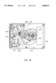
- FIG. 1A illustrates a prior art method of attaching a PCC to an actuator arm in a small form factor disc drive
- FIG. 1B illustrates the relative placement of the primary components seen in FIG. 1A in a small form factor disc drive
- FIG. 2 illustrates the printed circuit cable (PCC) and bracket in flat form before they are attached together;
- FIG. 3 illustrates the bending and shaping of the support bracket and printed circuit cable so that the bracket supports the cable
- FIGS. 4A and 4B are top and front elevational views of a formed bracket illustrating the relative position of the primary elements in the bracket.
- FIG. 5 illustrates the method of attachment of the formed PCC and support bracket to the actuator arm.
- the essential elements of a small form factor disc drive appear clearly therein including an actuator arm 114 driven by a voice coil motor 106 and carried on one end thereof to rotate the actuator arm about a pivot 108 and thereby position the transducer 110 carried on an end thereof over a selected track 116 on a disc 118.
- the transducer 110 reads and writes data on selected tracks on the surface of the disc. Its position is determined by the voice coil motor 106 which responds to electrical signals from a controller (not shown).
- the data read from the tracks on the disc is also transferred through an interface device generally indicated at 120 which is used to amplify the signals and transfer them to external circuitry which may be carried on a board on the underside of the disc drive and is therefore not shown or transferred through an interface through a processor which is not a part of the disc drive.
- FIG. 1A illustrates details of the printed circuit board 20, PCC 4, and actuator arm as designed and assembled in the prior art. It is the method of attaching the PCC 4 to the actuator arm 14 which is especially the subject of the present invention; however, to appreciate the advantages of the present invention, a review of the structure as defined in the prior art, together with the prior art method of assembly and attachment of the PCC to the actuator arm is necessary.
- the actuator arm 14 includes a substantially triangular shape actuator arm assembly 22 supporting flexure assembly 24 mounted at a pivot 26 around which the actuator arm 14 rotates.
- a coil assembly 28 is mounted at the opposite end of the pivot and on the same actuator arm 14 which supports the flexure assembly 24. This coil assembly cooperates with one or more fixed magnets (not shown) to form a voice coil motor and provide the force required to pivot the actuator arm 14 around the pivot 26.
- the coil assembly 28 includes a pair of extension pins 30 mounted on a molded terminal guard or coil support (not shown on FIG. 1A) for receiving the electrical control signals required to move the actuator arm assembly 14.
- a read/write head assembly 40 Located at the other end of the actuator arm 14 is a read/write head assembly 40.
- the coil assembly 28 responds to signals received at extension pins 30 to provide the force necessary to rotate the actuator arm assembly 14 about the pivot 26 to position the read/write head assembly 40 over a desired track on the rotating disc in the disc drive.
- a fixed printed circuit board 20 provides the interface between the external control devices which are not shown in this figure and the internal moving elements comprising the coil assembly 28 and read/write heads 40 so that the signals necessary for motor control or in reading and writing data through the read/write head 40 can be supplied through the printed circuit cable 4.
- the printed circuit cable 4 is firmly secured at each end to provide a stable connection at both the actuator arm mounting boss 12 and the end 2 of the printed circuit cable 4.
- the preferred embodiment of the present invention is focused on the necessity to provide a secure and easily assembled attachment of one end 2 of the printed circuit cable 4 to the actuator arm mounting boss 12.
- an L-shaped attachment bracket 6 including a hole 5 is aligned with the end 2 of the printed circuit cable 4, and the mounting boss 12 on the edge of actuator arm 14.
- a screw 9 is threaded through a washer 7, a hole 8 in the end 2 of the printed circuit cable 4, and the attachment bracket 6 and threaded into a hole 10 on the mounting boss 12.
- FIG. 2 illustrates the essential mechanical elements which are used to attach the printed circuit cable 2 running from the electrical cable which will run from the printed circuit board 20 to the actuator arm (not shown in FIG. 2) to thereby acquire the signals and transfer them from the read/write head (not shown in FIG. 2) to the printed circuit board 20.
- FIG. 2 illustrates the bracket 50, which is one of the primary elements used to implement this invention, shown in a flat form and positioned adjacent to the PCC 4 to which it will be attached.
- the bracket includes an opening 52 which is intended to be aligned with the hole 8 which is a standard feature of the PCC 4. This opening is used to align the PCC 4 and bracket 50.
- An enlarged portion 1 of the printed circuit cable 4 is intended to be bonded to the enlarged portion 54 of the bracket 50.
- the bracket is flat at this point and the combination of the PCC 4 and the bracket 50 creates a flat PCC assembly.
- the end 56 of the enlarged portion 1 of PCC 4 is fastened or bonded to the bracket 50 so that the forks 3 extend beyond the end 56 of the PCC 4. It should be noted this portion of the PCC terminating in the line 56 also includes a number of wire leads running through the PCC 4 and terminating at bonding pads so that printed circuit board 20 may be connected to wires on the actuator arm to carry the data signals to and from read/write head (not shown in FIG. 2).
- the bracket 50 in its flat form, is bonded using known techniques to one surface of the enlarged portion 1 of the PCC 4, and especially the section thereof which carries the bonding pads for receiving the wires which are run to the read/write head at the end of the actuator arms 14 (see FIG. 1B).
- the PCC 4 is further bonded over much of the bracket 50, not just in the region where the head wire solder pads are located.
- the L-shaped extension 57 of the PCC 4 which carries the control leads and bonding pads which will be wired to the coil assembly 28 is left hanging freely.
- the L-shaped piece 57 is captured and held in alignment by the bracket 50 (see FIG. 3), after the bracket 50 is formed as shown in FIGS. 4A and 4B.
- the forks 3 are bent inwardly toward the bracket and the antirotation tab 60 (shown in both FIGS. 2 and 3) is bent in the opposite direction. The bend in the forks 3 occurs beyond the end 56 of the PCC.
- a second and third bend 62 and 64 are used to further form the bracket so that it will fit against the side of the actuator arm 14 and butt up against the mounting boss 12.
- a fourth bend 68 is also used to hold the L-shaped extension (not shown in FIG. 4B) of the PCC against an end 66 of the bracket 50.
- this L-shaped extension 57 is folded back on itself as shown in FIG. 3, and the end 66 of the bracket is bent sharply around it so that both the exterior end 66 and interior end 65 (as shown in FIG. 4B) of the bracket 50 are pressed tightly against the L-shaped extension 57.
- the L-shaped extension 57 which is to run to the voice coil motor connection pins 30 is held fixedly in the proper orientation relative to the coil support 32 and pins 30.
- the remaining portion of the PCC 4 remains free to extend over toward the printed circuit board 20 as most clearly appears in FIG. 3 and FIG. 5.
- a preferred form of the method leaves L-shaped extension 57 hanging free during the forming operation.
- L-shaped extension 57 is then tucked into the slot between pieces 66 and 65 shown in FIG. 4B.
- the free end L-shaped extension 57 can be bonded to the outside of end 66 and bent into place with it; of course it then appears on the outside rather than the inside of the bracket.
- the flat PCC assembly has been shaped with a predetermined or designed shape to form a shaped PCC assembly for installation onto the actuator arm.
- the L-shaped extension 57 of the PCC 4 fits over the pins 30 of coil support 32 so that easy connection of the control wires to the coil assembly 28 is facilitated.
- the solder bonding pads 88 of the PCC are now supported on the bracket frame for easy attachment to the wires running to the read/write head 40 supported at the ends of the actuator arm 14.
- this assembly method provides for a one-piece PCC and bracket, assembled onto the actuator arm in a standard round washer and screw.
- the antirotation tab 60 eliminates both alignment and rotation problems to facilitate adoption of automatic assembly techniques.
Abstract
Description
Claims (3)
Priority Applications (1)
| Application Number | Priority Date | Filing Date | Title |
|---|---|---|---|
| US08/581,758 US5680277A (en) | 1994-03-02 | 1996-01-02 | Apparatus for attaching a printed circuit cable to actuator arm disc drive assembly |
Applications Claiming Priority (2)
| Application Number | Priority Date | Filing Date | Title |
|---|---|---|---|
| US20593194A | 1994-03-02 | 1994-03-02 | |
| US08/581,758 US5680277A (en) | 1994-03-02 | 1996-01-02 | Apparatus for attaching a printed circuit cable to actuator arm disc drive assembly |
Related Parent Applications (1)
| Application Number | Title | Priority Date | Filing Date |
|---|---|---|---|
| US20593194A Continuation | 1994-03-02 | 1994-03-02 |
Publications (1)
| Publication Number | Publication Date |
|---|---|
| US5680277A true US5680277A (en) | 1997-10-21 |
Family
ID=22764256
Family Applications (3)
| Application Number | Title | Priority Date | Filing Date |
|---|---|---|---|
| US08/367,932 Expired - Lifetime US5655285A (en) | 1994-03-02 | 1995-03-27 | Method for attaching a printed circuit cable to an actuator arm in a disc drive assembly |
| US08/367,940 Expired - Lifetime US5584451A (en) | 1994-03-02 | 1995-03-27 | Apparatus for attaching a printed circuit cable to an actuator arm in a disc drive assembly using formed PCC bracket |
| US08/581,758 Expired - Fee Related US5680277A (en) | 1994-03-02 | 1996-01-02 | Apparatus for attaching a printed circuit cable to actuator arm disc drive assembly |
Family Applications Before (2)
| Application Number | Title | Priority Date | Filing Date |
|---|---|---|---|
| US08/367,932 Expired - Lifetime US5655285A (en) | 1994-03-02 | 1995-03-27 | Method for attaching a printed circuit cable to an actuator arm in a disc drive assembly |
| US08/367,940 Expired - Lifetime US5584451A (en) | 1994-03-02 | 1995-03-27 | Apparatus for attaching a printed circuit cable to an actuator arm in a disc drive assembly using formed PCC bracket |
Country Status (1)
| Country | Link |
|---|---|
| US (3) | US5655285A (en) |
Cited By (20)
| Publication number | Priority date | Publication date | Assignee | Title |
|---|---|---|---|---|
| US5844753A (en) * | 1995-04-13 | 1998-12-01 | Nippon Mektron Ltd. | Magnetic head junction board and manufacturing method for the same |
| US5886858A (en) * | 1997-03-28 | 1999-03-23 | Kabushiki Kaisha Toshiba | Magnetic disk apparatus with flexible printed circuit board connected to carriage assembly |
| US5905609A (en) * | 1997-11-14 | 1999-05-18 | Western Digital Corporation | Magnetic disk drive having a VCM plate which includes an elongated protrusion for securing a flex clamp to the base |
| US6556386B1 (en) * | 1995-10-31 | 2003-04-29 | Fujitsu Limited | FPC connection arrangement for a disk unit |
| US20030137776A1 (en) * | 2002-01-24 | 2003-07-24 | Liyang Zhoa | Contacting point damping method between flex circuit and pivot housing |
| US20030147180A1 (en) * | 2002-02-07 | 2003-08-07 | Seagate Technology Llc | Flex cable assembly with improved flex cable dynamic loop characteristics |
| US6765763B2 (en) | 2000-06-16 | 2004-07-20 | Seagate Technology Llc | Actuator system for disc drive |
| KR100505580B1 (en) * | 1997-12-31 | 2005-10-05 | 삼성전자주식회사 | FPC retainer on hard disk drive |
| US20060039087A1 (en) * | 2004-08-23 | 2006-02-23 | Sae Magnetics (H.K.) Ltd. | Head stack assembly and manufacturing method thereof, and disk drive unit using the same |
| US7059868B1 (en) | 2000-03-07 | 2006-06-13 | Western Digital (Fremont), Inc. | Connection of trace circuitry in a computer disk drive system |
| US20060164762A1 (en) * | 2004-12-31 | 2006-07-27 | Samsung Electronics Co., Ltd. | Hard disk drive connecting a flexible printed circuit and actuator arm and method thereof |
| US20060276058A1 (en) * | 2005-06-01 | 2006-12-07 | Seagate Technology Llc | Method and apparatus for attenuating flexible circuit resonance |
| US7180711B1 (en) * | 2004-03-31 | 2007-02-20 | Western Digital Technologies, Inc. | Head stack assembly with an actuator body and flex cable guiding support and method of making the same |
| US20070097552A1 (en) * | 2005-10-31 | 2007-05-03 | Haeng-Soo Lee | Hard disk drive and flexible printed circuit ribbon thereof |
| US20080055771A1 (en) * | 2006-08-30 | 2008-03-06 | Fujitsu Limited | Head stack assembly, and storage having the same |
| EP1501079A3 (en) * | 2003-07-24 | 2008-04-09 | Matsushita Electric Industrial Co., Ltd. | Head supporting device and disk apparatus |
| US20080151429A1 (en) * | 2006-12-20 | 2008-06-26 | Hitachi Global Storage Technologies Netherlands B.V. | Magnetic disk device |
| US7414814B1 (en) * | 2005-04-28 | 2008-08-19 | Western Digital Technologies, Inc. | Disk drives, head stack, head gimbal and suspension assemblies having a compliant suspension tail design for solder reflow |
| US20100123976A1 (en) * | 2008-11-19 | 2010-05-20 | Seagate Technology Llc | Arm mounted shock sensor and flexible circuit routing |
| US9001470B1 (en) * | 2013-12-17 | 2015-04-07 | HGST Netherlands B.V. | Flexible printed circuit board stiffener for hard disk drive |
Families Citing this family (19)
| Publication number | Priority date | Publication date | Assignee | Title |
|---|---|---|---|---|
| FR2754577B1 (en) * | 1996-10-11 | 1998-12-11 | Suisse Electronique Microtech | PLANAR FLEXIBLE PIVOT WITH MONOLITHIC UNIT MODULES |
| KR100441838B1 (en) * | 1997-01-31 | 2004-10-08 | 삼성전자주식회사 | Flexible print circuit cable having two-layer structure for low voltage differential signal transmission, including plural signal transmission lines arranged at both sides of insulation layer |
| KR100441847B1 (en) * | 1997-02-05 | 2004-10-26 | 삼성전자주식회사 | Flexible print circuit cable having two-layer structure for low voltage differential signal transmission, including signal transmission lines arranged into zigzag shapes on both sides of insulation layer |
| US6049969A (en) * | 1997-10-16 | 2000-04-18 | Seagate Technology, Inc. | Head-disc merge station for a disc drive |
| US5907452A (en) * | 1997-10-20 | 1999-05-25 | International Business Machines Corporation | Apparatus and method to dampen flex cable vibration to disk drive actuator |
| US6135782A (en) * | 1998-06-05 | 2000-10-24 | Seagate Technology, Inc. | Electrical compression connector for a disc drive |
| US6716363B1 (en) | 1999-04-20 | 2004-04-06 | Seagate Technology Llc | Electrode patterning for a differential PZT activator |
| US6702592B1 (en) | 1999-12-03 | 2004-03-09 | Seagate Technology Llc | Printed circuit board assembly with secondary side rigid electrical pin to mate with compliant contact |
| US6636383B1 (en) | 2000-03-17 | 2003-10-21 | Maxtor Corporation | Disk drive actuator arm assembly with unitary flex cable |
| US6687093B1 (en) | 2001-05-31 | 2004-02-03 | Western Digital Technologies, Inc. | Head stack assembly shipping comb with temporary locating feature for internal head disk assembly build process and disk drive manufactured using the same |
| JP2003173635A (en) * | 2001-12-04 | 2003-06-20 | Seiko Instruments Inc | Fpc arranging apparatus |
| US20030179505A1 (en) * | 2002-03-19 | 2003-09-25 | Jang Eun Kyu | One piece interconnect from channel chip to head slider in a voice coil actuator for a disk drive |
| US6934126B1 (en) * | 2002-12-23 | 2005-08-23 | Western Digital Technologies, Inc. | Disk drive including a base assembly having a flex-to-board edge connector |
| WO2005006331A1 (en) * | 2003-07-14 | 2005-01-20 | Sae Magnetics (H.K.) Ltd. | System and method for improving the electrical connection of a hard drive relay flexible circuit assembly to an hga flexure cable |
| US20070153415A1 (en) * | 2006-01-04 | 2007-07-05 | Jen-Yuan Chang | Constrained-damped boundary apparatus for reduction of HDD flex cable induced settle dynamics |
| JP4331738B2 (en) * | 2006-05-30 | 2009-09-16 | 富士通株式会社 | Arrangement method of flexible printed circuit board |
| JP2009238271A (en) * | 2008-03-26 | 2009-10-15 | Fujitsu Ltd | Disk drive |
| US9553385B2 (en) * | 2015-06-18 | 2017-01-24 | Dxo Labs | Electronic device comprising an electronic connector and a flexible printed circuit |
| IT201800010651A1 (en) | 2018-11-28 | 2020-05-28 | I D I Evolution S R L | CONNECTION BETWEEN DENTAL IMPLANTS AND PROSTHETIC DEVICES |
Citations (2)
| Publication number | Priority date | Publication date | Assignee | Title |
|---|---|---|---|---|
| US5267376A (en) * | 1990-11-09 | 1993-12-07 | Seagate Technology, Inc. | Apparatus for attaching a printed circuit cable mount |
| US5455728A (en) * | 1991-12-04 | 1995-10-03 | Digital Corporation | Disk drive employing compact magnetic actuator latch mechanism |
Family Cites Families (17)
| Publication number | Priority date | Publication date | Assignee | Title |
|---|---|---|---|---|
| US1067702A (en) * | 1910-06-29 | 1913-07-15 | Cutler Hammer Mfg Co | Terminal lug. |
| US1566465A (en) * | 1921-05-18 | 1925-12-22 | Ac Spark Plug Co | Terminal connecter for spark plugs |
| US2541828A (en) * | 1945-08-02 | 1951-02-13 | Mallory & Co Inc P R | Condenser mounting clip |
| US2618033A (en) * | 1950-03-16 | 1952-11-18 | Tinnerman Products Inc | Cable clamp or the like |
| US2826387A (en) * | 1953-11-02 | 1958-03-11 | Edward N Rutten | Holder for glasses |
| US3302912A (en) * | 1965-07-07 | 1967-02-07 | Automatic Switch Co | Mounting bracket for valves |
| CH672673A5 (en) * | 1987-02-28 | 1989-12-15 | Daniel Andenmatten | Pipe fixture for pre-concreting work - consists of two vertical toothed struts with U=shaped cross section, bar and locking pieces |
| US4965684A (en) * | 1988-01-25 | 1990-10-23 | Conner Peripherals, Inc. | Low height disk drive |
| US4915650A (en) * | 1988-05-13 | 1990-04-10 | Amp Incorporated | Electrical terminals and method for terminating flat power cable |
| US5216581A (en) * | 1990-02-05 | 1993-06-01 | Motorola, Inc. | Electronic module assembly and method of forming same |
| US5170326A (en) * | 1990-02-05 | 1992-12-08 | Motorola, Inc. | Electronic module assembly |
| US5103375A (en) * | 1990-02-05 | 1992-04-07 | Motorola, Inc. | Electronic module assembly and method of manufacture |
| DE59300033D1 (en) * | 1992-02-04 | 1995-01-19 | Ulrich Gantenbein | Fastening rail, especially for cables and electrical pipes. |
| US5364051A (en) * | 1993-04-29 | 1994-11-15 | Teledyne Industries Inc. | Locator clip |
| US5375021A (en) * | 1993-05-13 | 1994-12-20 | Maxtor Corporation | Bracket assembly which creates a pair of loops in a flexible circuit board that couples an actuator arm to the control circuits of a hard disk drive |
| US5495377A (en) * | 1993-05-27 | 1996-02-27 | Seagate Technology, Inc. | Apparatus for attaching a printed circuit cable to an actuator arm in a disc drive assembly utilizing alignment pins |
| US5434362A (en) * | 1994-09-06 | 1995-07-18 | Motorola, Inc. | Flexible circuit board assembly and method |
-
1995
- 1995-03-27 US US08/367,932 patent/US5655285A/en not_active Expired - Lifetime
- 1995-03-27 US US08/367,940 patent/US5584451A/en not_active Expired - Lifetime
-
1996
- 1996-01-02 US US08/581,758 patent/US5680277A/en not_active Expired - Fee Related
Patent Citations (2)
| Publication number | Priority date | Publication date | Assignee | Title |
|---|---|---|---|---|
| US5267376A (en) * | 1990-11-09 | 1993-12-07 | Seagate Technology, Inc. | Apparatus for attaching a printed circuit cable mount |
| US5455728A (en) * | 1991-12-04 | 1995-10-03 | Digital Corporation | Disk drive employing compact magnetic actuator latch mechanism |
Cited By (28)
| Publication number | Priority date | Publication date | Assignee | Title |
|---|---|---|---|---|
| US5844753A (en) * | 1995-04-13 | 1998-12-01 | Nippon Mektron Ltd. | Magnetic head junction board and manufacturing method for the same |
| US6556386B1 (en) * | 1995-10-31 | 2003-04-29 | Fujitsu Limited | FPC connection arrangement for a disk unit |
| US5886858A (en) * | 1997-03-28 | 1999-03-23 | Kabushiki Kaisha Toshiba | Magnetic disk apparatus with flexible printed circuit board connected to carriage assembly |
| US5905609A (en) * | 1997-11-14 | 1999-05-18 | Western Digital Corporation | Magnetic disk drive having a VCM plate which includes an elongated protrusion for securing a flex clamp to the base |
| KR100505580B1 (en) * | 1997-12-31 | 2005-10-05 | 삼성전자주식회사 | FPC retainer on hard disk drive |
| US7059868B1 (en) | 2000-03-07 | 2006-06-13 | Western Digital (Fremont), Inc. | Connection of trace circuitry in a computer disk drive system |
| US6765763B2 (en) | 2000-06-16 | 2004-07-20 | Seagate Technology Llc | Actuator system for disc drive |
| US20030137776A1 (en) * | 2002-01-24 | 2003-07-24 | Liyang Zhoa | Contacting point damping method between flex circuit and pivot housing |
| US6937442B2 (en) | 2002-01-24 | 2005-08-30 | Seagate Technology Llc | Contacting point damping method between flex circuit and pivot housing |
| US20030147180A1 (en) * | 2002-02-07 | 2003-08-07 | Seagate Technology Llc | Flex cable assembly with improved flex cable dynamic loop characteristics |
| US6856490B2 (en) | 2002-02-07 | 2005-02-15 | Seagate Technology Llc | Flex cable assembly with improved flex cable dynamic loop characteristics |
| EP1501079A3 (en) * | 2003-07-24 | 2008-04-09 | Matsushita Electric Industrial Co., Ltd. | Head supporting device and disk apparatus |
| US7180711B1 (en) * | 2004-03-31 | 2007-02-20 | Western Digital Technologies, Inc. | Head stack assembly with an actuator body and flex cable guiding support and method of making the same |
| US20060039087A1 (en) * | 2004-08-23 | 2006-02-23 | Sae Magnetics (H.K.) Ltd. | Head stack assembly and manufacturing method thereof, and disk drive unit using the same |
| US7362545B2 (en) * | 2004-08-23 | 2008-04-22 | Sae Magnetics (H.K.) Ltd. | Head stack assembly and manufacturing method thereof, and disk drive unit using the same |
| US7616408B2 (en) | 2004-12-31 | 2009-11-10 | Samsung Electronics Co., Ltd. | Hard disk drive connecting a flexible printed circuit and actuator having vertical mating |
| US20060164762A1 (en) * | 2004-12-31 | 2006-07-27 | Samsung Electronics Co., Ltd. | Hard disk drive connecting a flexible printed circuit and actuator arm and method thereof |
| US7414814B1 (en) * | 2005-04-28 | 2008-08-19 | Western Digital Technologies, Inc. | Disk drives, head stack, head gimbal and suspension assemblies having a compliant suspension tail design for solder reflow |
| US7271345B2 (en) | 2005-06-01 | 2007-09-18 | Seagate Technology Llc | Method and apparatus for attenuating flexible circuit resonance |
| US20060276058A1 (en) * | 2005-06-01 | 2006-12-07 | Seagate Technology Llc | Method and apparatus for attenuating flexible circuit resonance |
| US20070097552A1 (en) * | 2005-10-31 | 2007-05-03 | Haeng-Soo Lee | Hard disk drive and flexible printed circuit ribbon thereof |
| US20080055771A1 (en) * | 2006-08-30 | 2008-03-06 | Fujitsu Limited | Head stack assembly, and storage having the same |
| US7692900B2 (en) * | 2006-08-30 | 2010-04-06 | Toshiba Storage Device Corporation | Head stack assembly, and storage having the same |
| US20080151429A1 (en) * | 2006-12-20 | 2008-06-26 | Hitachi Global Storage Technologies Netherlands B.V. | Magnetic disk device |
| US8130472B2 (en) * | 2006-12-20 | 2012-03-06 | Hitachi Global Storage Technologies, Netherlands B.V. | Head support for a magnetic disk device |
| US20100123976A1 (en) * | 2008-11-19 | 2010-05-20 | Seagate Technology Llc | Arm mounted shock sensor and flexible circuit routing |
| US8111485B2 (en) | 2008-11-19 | 2012-02-07 | Seagate Technology Llc | Arm mounted shock sensor and flexible circuit routing |
| US9001470B1 (en) * | 2013-12-17 | 2015-04-07 | HGST Netherlands B.V. | Flexible printed circuit board stiffener for hard disk drive |
Also Published As
| Publication number | Publication date |
|---|---|
| US5655285A (en) | 1997-08-12 |
| US5584451A (en) | 1996-12-17 |
Similar Documents
| Publication | Publication Date | Title |
|---|---|---|
| US5680277A (en) | Apparatus for attaching a printed circuit cable to actuator arm disc drive assembly | |
| KR100277559B1 (en) | Flexible Printed Circuit Cable, Carriage Unit, and Disk Drive | |
| US5495377A (en) | Apparatus for attaching a printed circuit cable to an actuator arm in a disc drive assembly utilizing alignment pins | |
| JP3199977B2 (en) | Disk unit | |
| US5717541A (en) | Flexible circuit assembly for disk storage system | |
| US8472145B2 (en) | Arm coil assembly, arm flexible cable assembly and disk drive unit with the same | |
| WO2001099104A3 (en) | Head pitch adjustment for disc drive | |
| US6018439A (en) | Connector assembly for connecting transducing heads to a flex circuit of a disc drive | |
| JPH09153263A (en) | Integrated lead suspension | |
| US11240919B2 (en) | Connecting device and disk device | |
| US6765763B2 (en) | Actuator system for disc drive | |
| US5343344A (en) | Connection of transducer leads to a printed circuit board in rotating disk data storage apparatus | |
| US7542231B2 (en) | Disc drive apparatus having drive electronics top mounted on flexible printed circuit board | |
| US7859796B2 (en) | Disk drive and arm coil support assembly | |
| US6388834B1 (en) | Grounding post to reduce EMI noise effects in disc drives | |
| US7355818B2 (en) | Disc drive integral actuator pins | |
| JP3139950B2 (en) | Wiring structure of load beam and guide arm of magnetic disk drive | |
| US6549506B1 (en) | Photo detector mounting in a head gimbal assembly used in an optical data storage device | |
| EP0582463B1 (en) | Voice coil motor and disc drive | |
| JP3256983B2 (en) | Magnetic disk drive and support spring | |
| US7012787B2 (en) | Head suspension assembly for hard disk drive | |
| US6356413B2 (en) | Chip-mounted disk drive suspension | |
| JPH039173Y2 (en) | ||
| KR100212989B1 (en) | Head suspension assembly of hard disk drive | |
| JPH04115393U (en) | magnetic recording and reproducing device |
Legal Events
| Date | Code | Title | Description |
|---|---|---|---|
| FEPP | Fee payment procedure |
Free format text: PAYOR NUMBER ASSIGNED (ORIGINAL EVENT CODE: ASPN); ENTITY STATUS OF PATENT OWNER: LARGE ENTITY |
|
| AS | Assignment |
Owner name: SEAGATE TECHNOLOGY LLC, CALIFORNIA Free format text: ASSIGNMENT OF ASSIGNORS INTEREST;ASSIGNOR:SEAGATE TECHNOLOGY, INC.;REEL/FRAME:011077/0319 Effective date: 20000728 |
|
| FEPP | Fee payment procedure |
Free format text: PAYER NUMBER DE-ASSIGNED (ORIGINAL EVENT CODE: RMPN); ENTITY STATUS OF PATENT OWNER: LARGE ENTITY Free format text: PAYOR NUMBER ASSIGNED (ORIGINAL EVENT CODE: ASPN); ENTITY STATUS OF PATENT OWNER: LARGE ENTITY |
|
| AS | Assignment |
Owner name: THE CHASE MANHATTAN BANK, AS COLLATERAL AGENT, NEW Free format text: SECURITY AGREEMENT;ASSIGNOR:SEAGATE TECHNOLOGY LLC;REEL/FRAME:011461/0001 Effective date: 20001122 |
|
| FPAY | Fee payment |
Year of fee payment: 4 |
|
| AS | Assignment |
Owner name: JPMORGAN CHASE BANK, AS COLLATERAL AGENT, NEW YORK Free format text: SECURITY AGREEMENT;ASSIGNOR:SEAGATE TECHNOLOGY LLC;REEL/FRAME:013177/0001 Effective date: 20020513 Owner name: JPMORGAN CHASE BANK, AS COLLATERAL AGENT,NEW YORK Free format text: SECURITY AGREEMENT;ASSIGNOR:SEAGATE TECHNOLOGY LLC;REEL/FRAME:013177/0001 Effective date: 20020513 |
|
| FPAY | Fee payment |
Year of fee payment: 8 |
|
| AS | Assignment |
Owner name: SEAGATE TECHNOLOGY LLC, CALIFORNIA Free format text: RELEASE OF SECURITY INTERESTS IN PATENT RIGHTS;ASSIGNOR:JPMORGAN CHASE BANK, N.A. (FORMERLY KNOWN AS THE CHASE MANHATTAN BANK AND JPMORGAN CHASE BANK), AS ADMINISTRATIVE AGENT;REEL/FRAME:016945/0679 Effective date: 20051130 |
|
| REMI | Maintenance fee reminder mailed | ||
| AS | Assignment |
Owner name: JPMORGAN CHASE BANK, N.A., AS ADMINISTRATIVE AGENT Free format text: SECURITY AGREEMENT;ASSIGNORS:MAXTOR CORPORATION;SEAGATE TECHNOLOGY LLC;SEAGATE TECHNOLOGY INTERNATIONAL;REEL/FRAME:022757/0017 Effective date: 20090507 Owner name: WELLS FARGO BANK, NATIONAL ASSOCIATION, AS COLLATE Free format text: SECURITY AGREEMENT;ASSIGNORS:MAXTOR CORPORATION;SEAGATE TECHNOLOGY LLC;SEAGATE TECHNOLOGY INTERNATIONAL;REEL/FRAME:022757/0017 Effective date: 20090507 |
|
| LAPS | Lapse for failure to pay maintenance fees | ||
| STCH | Information on status: patent discontinuation |
Free format text: PATENT EXPIRED DUE TO NONPAYMENT OF MAINTENANCE FEES UNDER 37 CFR 1.362 |
|
| FP | Lapsed due to failure to pay maintenance fee |
Effective date: 20091021 |
|
| AS | Assignment |
Owner name: SEAGATE TECHNOLOGY INTERNATIONAL, CALIFORNIA Free format text: RELEASE;ASSIGNOR:JPMORGAN CHASE BANK, N.A., AS ADMINISTRATIVE AGENT;REEL/FRAME:025662/0001 Effective date: 20110114 Owner name: SEAGATE TECHNOLOGY HDD HOLDINGS, CALIFORNIA Free format text: RELEASE;ASSIGNOR:JPMORGAN CHASE BANK, N.A., AS ADMINISTRATIVE AGENT;REEL/FRAME:025662/0001 Effective date: 20110114 Owner name: SEAGATE TECHNOLOGY LLC, CALIFORNIA Free format text: RELEASE;ASSIGNOR:JPMORGAN CHASE BANK, N.A., AS ADMINISTRATIVE AGENT;REEL/FRAME:025662/0001 Effective date: 20110114 Owner name: MAXTOR CORPORATION, CALIFORNIA Free format text: RELEASE;ASSIGNOR:JPMORGAN CHASE BANK, N.A., AS ADMINISTRATIVE AGENT;REEL/FRAME:025662/0001 Effective date: 20110114 |
|
| AS | Assignment |
Owner name: SEAGATE TECHNOLOGY LLC, CALIFORNIA Free format text: TERMINATION AND RELEASE OF SECURITY INTEREST IN PATENT RIGHTS;ASSIGNOR:WELLS FARGO BANK, NATIONAL ASSOCIATION, AS COLLATERAL AGENT AND SECOND PRIORITY REPRESENTATIVE;REEL/FRAME:030833/0001 Effective date: 20130312 Owner name: SEAGATE TECHNOLOGY INTERNATIONAL, CAYMAN ISLANDS Free format text: TERMINATION AND RELEASE OF SECURITY INTEREST IN PATENT RIGHTS;ASSIGNOR:WELLS FARGO BANK, NATIONAL ASSOCIATION, AS COLLATERAL AGENT AND SECOND PRIORITY REPRESENTATIVE;REEL/FRAME:030833/0001 Effective date: 20130312 Owner name: EVAULT INC. (F/K/A I365 INC.), CALIFORNIA Free format text: TERMINATION AND RELEASE OF SECURITY INTEREST IN PATENT RIGHTS;ASSIGNOR:WELLS FARGO BANK, NATIONAL ASSOCIATION, AS COLLATERAL AGENT AND SECOND PRIORITY REPRESENTATIVE;REEL/FRAME:030833/0001 Effective date: 20130312 Owner name: SEAGATE TECHNOLOGY US HOLDINGS, INC., CALIFORNIA Free format text: TERMINATION AND RELEASE OF SECURITY INTEREST IN PATENT RIGHTS;ASSIGNOR:WELLS FARGO BANK, NATIONAL ASSOCIATION, AS COLLATERAL AGENT AND SECOND PRIORITY REPRESENTATIVE;REEL/FRAME:030833/0001 Effective date: 20130312 |