US5672925A - Doubly salient variable reluctance machine with stationary permanent magnets or auxiliary field windings - Google Patents

Doubly salient variable reluctance machine with stationary permanent magnets or auxiliary field windings Download PDF

Info

Publication number
US5672925A
US5672925A US08/514,495 US51449595A US5672925A US 5672925 A US5672925 A US 5672925A US 51449595 A US51449595 A US 51449595A US 5672925 A US5672925 A US 5672925A
Authority
US
United States
Prior art keywords
stator
yoke
rotor
poles
machine
Prior art date
Legal status (The legal status is an assumption and is not a legal conclusion. Google has not performed a legal analysis and makes no representation as to the accuracy of the status listed.)
Expired - Fee Related
Application number
US08/514,495
Inventor
Thomas A. Lipo
Yuefeng Liao
Feng Liang
Current Assignee (The listed assignees may be inaccurate. Google has not performed a legal analysis and makes no representation or warranty as to the accuracy of the list.)
Electric Power Research Institute Inc
Original Assignee
Electric Power Research Institute Inc
Priority date (The priority date is an assumption and is not a legal conclusion. Google has not performed a legal analysis and makes no representation as to the accuracy of the date listed.)
Filing date
Publication date
Priority claimed from US07/926,765 external-priority patent/US5825112A/en
Application filed by Electric Power Research Institute Inc filed Critical Electric Power Research Institute Inc
Priority to US08/514,495 priority Critical patent/US5672925A/en
Assigned to ELECTRIC POWER RESEARCH INSTITUTE, INC. reassignment ELECTRIC POWER RESEARCH INSTITUTE, INC. ASSIGNMENT OF ASSIGNORS INTEREST (SEE DOCUMENT FOR DETAILS). Assignors: LIANG, FENG
Assigned to ELECTRIC POWER RESEARCH INSTITUTE, INC. reassignment ELECTRIC POWER RESEARCH INSTITUTE, INC. ASSIGNMENT OF ASSIGNORS INTEREST (SEE DOCUMENT FOR DETAILS). Assignors: LIAO, YUEFENG
Assigned to ELECTRIC POWER RESEARCH INSTITUTE, INC. reassignment ELECTRIC POWER RESEARCH INSTITUTE, INC. ASSIGNMENT OF ASSIGNORS INTEREST (SEE DOCUMENT FOR DETAILS). Assignors: LIPO, THOMAS A.
Priority to AU55665/96A priority patent/AU5566596A/en
Priority to PCT/US1996/005618 priority patent/WO1997007583A1/en
Application granted granted Critical
Publication of US5672925A publication Critical patent/US5672925A/en
Anticipated expiration legal-status Critical
Expired - Fee Related legal-status Critical Current

Links

Images

Classifications

    • HELECTRICITY
    • H02GENERATION; CONVERSION OR DISTRIBUTION OF ELECTRIC POWER
    • H02KDYNAMO-ELECTRIC MACHINES
    • H02K19/00Synchronous motors or generators
    • H02K19/02Synchronous motors
    • H02K19/10Synchronous motors for multi-phase current
    • H02K19/103Motors having windings on the stator and a variable reluctance soft-iron rotor without windings
    • HELECTRICITY
    • H02GENERATION; CONVERSION OR DISTRIBUTION OF ELECTRIC POWER
    • H02KDYNAMO-ELECTRIC MACHINES
    • H02K19/00Synchronous motors or generators
    • H02K19/16Synchronous generators
    • H02K19/22Synchronous generators having windings each turn of which co-operates alternately with poles of opposite polarity, e.g. heteropolar generators
    • H02K19/24Synchronous generators having windings each turn of which co-operates alternately with poles of opposite polarity, e.g. heteropolar generators with variable-reluctance soft-iron rotors without winding
    • HELECTRICITY
    • H02GENERATION; CONVERSION OR DISTRIBUTION OF ELECTRIC POWER
    • H02KDYNAMO-ELECTRIC MACHINES
    • H02K21/00Synchronous motors having permanent magnets; Synchronous generators having permanent magnets
    • H02K21/38Synchronous motors having permanent magnets; Synchronous generators having permanent magnets with rotating flux distributors, and armatures and magnets both stationary
    • H02K21/44Synchronous motors having permanent magnets; Synchronous generators having permanent magnets with rotating flux distributors, and armatures and magnets both stationary with armature windings wound upon the magnets
    • HELECTRICITY
    • H02GENERATION; CONVERSION OR DISTRIBUTION OF ELECTRIC POWER
    • H02KDYNAMO-ELECTRIC MACHINES
    • H02K29/00Motors or generators having non-mechanical commutating devices, e.g. discharge tubes or semiconductor devices
    • H02K29/03Motors or generators having non-mechanical commutating devices, e.g. discharge tubes or semiconductor devices with a magnetic circuit specially adapted for avoiding torque ripples or self-starting problems

Definitions

  • the VRM has fallen short of its above-described potential for two reasons.
  • the VRM suffers from an "excitation penalty," i.e., the armature current must provide an excitation component.
  • the VRM has a lower efficiency and lower power factor (or energy ratio) as compared with other motors wherein the stator current is solely for torque production.
  • ideal switching conditions do not exist, and attempts to achieve such conditions have resulted in commercially impractical converter circuits with excessive voltage and current stresses imparted to the switching devices.
  • the current in each phase should be decreased to zero immediately when the rotor is aligned with that phase.
  • the problem lies in the existence of a large turn-off inductance.
  • the phase inductance is a maximum when the rotor is aligned with that phase. Since this large inductance will draw a residual current due to the energy stored in the magnetic field, the current in each phase cannot immediately be decreased to zero when the rotor reaches alignment. Consequently, the decaying residual current induces a detrimental reverse-torque as the rotor pole passes alignment with the corresponding stator pole. The problem is most serious when the speed of the motor is high. As a result, those skilled in the art view present VRM technology with some skepticism. Synchronous or induction motors remain the industry choice.
  • U.S. Pat. No. 5,304,882 owned by the assignee of the present invention, provides one solution in the form of a high output permanent magnet motor incorporating one or more permanent magnets in the rotor.
  • the invention also provides a machine having the same structure and double saliency as described above except that the permanent magnets are replaced by an auxiliary field winding.
  • the auxiliary field winding is excited by DC to provide flux in the magnetic circuit of the machine. It is clear that the invention also provides for a machine having both permanent magnets and auxiliary field windings since both means of excitation can be accommodated simultaneously.
  • FIG. 1 is a cross-section of a doubly salient stationary permanent magnet machine (SP 2 M) having four stator poles and six rotor poles according to one embodiment of the present invention.
  • SP 2 M doubly salient stationary permanent magnet machine
  • FIG. 3 is a composite graph showing the currents i a-b (in dotted lines) superposed over the corresponding flux linkages ⁇ a-b in each of the respective phases A-B resulting from the permanent magnets 22 and 24 in the SP 2 M embodiment of FIG. 1.
  • the switching sequences of the switch elements of the converter circuit of FIG. 4 are shown in lines A and B.
  • FIG. 6 is a cross-section of a doubly salient machine similar to that of FIG. 1 except that the permanent magnets are replaced by two auxiliary field windings F1 and F2 according to a fourth embodiment of the present invention.
  • FIG. 7 is a circuit diagram of a converter circuit, stator winding connections, and auxiliary field winding connections which may be employed for operating the embodiment of FIG. 6 as a DC generator.
  • FIG. 1 shows a cross-section of a doubly salient stationary permanent magnet machine (SP 2 M) according to one embodiment of the present invention.
  • a stator 10 consists of a plurality of discrete laminated layers, each layer being punched to form a pair of yoke sections 11A, 11B, each section having two salient (or projecting) poles 12 positioned at angular intervals of ⁇ /2 radians.
  • Each pole 12 has a pole arc ⁇ ps of ⁇ /6 radians.
  • the rotor 16 also consists of a plurality of discrete laminated layers each of which are punched to form six salient poles 18 positioned at angular intervals ⁇ r of ⁇ /3.
  • Each pole 18 also has a pole arc ⁇ pr equal to or slightly greater than ⁇ /6 radians.
  • the winding arrangement yields the following exemplary alternating sequence during one complete revolution:
  • Magnets 22 and 24 are polarized transversely to the stator axis, with like polarities of each magnet facing in the same direction and contacting the same one of punchings 11A or 11B at opposite ends thereof. That is, the north poles of both magnets 22 and 24 face stator punchings 11A and the south poles of both magnets face stator punchings 11B. If desired, the polarities of both magnets may be reversed.
  • any conventional fixative can be used to secure the permanent magnets 22 and 24.
  • stator pole 12 and rotor pole 18 arrangement of the present invention ensures that the total overlapped pole area remains constant for all positions of rotor 16. This way, the total air-gap reluctance (which is the primary reluctance for the permanent magnet excitation) is invariant to rotor 16 displacement ⁇ d , and there exists a substantially linear transfer of permanent magnet flux between adjacent stator poles 12 during rotation of rotor 16. Consequently, permanent magnets 22 and 24 produce no cogging torque at no load.
  • stator poles to rotor poles are inverted as compared to the present invention.
  • stator is equipped with six salient poles wound for three phases and the rotor includes four salient poles.
  • the machine operates in such a manner that only two of the three phases are carrying current at any time. Hence, only 2/3 of the copper of the machine can be considered as "active" at any instant of time.
  • both phases are carrying current at every time instant (except for the brief instants when the current reverses polarity).
  • all of the copper is active at any instant, resulting in an improved utilization of copper within the machine compared to the machine of application Ser. No. 07/926,765.
  • FIG. 2 illustrates the basic structure for a machine incorporating a stator 110 having eight poles and a rotor 116 having twelve poles.
  • the number of permanent magnets is multiplied accordingly, and four such magnets 121-124 are employed in the embodiment of FIG. 2 allowing magnets to be placed in all four corners of the stator.
  • Four similar stator sections 111A-111D, each having two salient poles 112 are used in the embodiment of FIG. 2.
  • the magnets 121-124 are polarized transversely to the central axis of the machine and the magnet faces abutting the opposite ends of each of sections 111A-111D are of like polarity.
  • each of the stator poles 112 is wound with a coil A1-A4 and B1-B4 and the coils of diametrically opposed stator poles are connected together to form four windings, i.e., A1-A2, A3-A4, B1-B2, and B3-B4.
  • the flux linkage ⁇ a and ⁇ b of each stator pole 12 increases at a constant rate for continuing rotor 16 displacement ⁇ d until full alignment of a diametric pair of stator poles 12 and rotor poles 18.
  • the flux linkages ⁇ A and ⁇ B of the respective pole pairs decrease at a constant rate.
  • the armature reaction field energy W f which is to be recovered during current commutation, is greatly reduced because of the much smaller value of the stator 10 inductance. Therefore, the energy ratio, or equivalently, the power factor is very high.
  • the smaller value of the stator inductance also makes the dynamic response of the motor much faster.
  • the stator windings A and B meet small permeances at both aligned and unaligned positions, even though a great deal of permanent magnet flux concentration is achieved under the overlapped pole pairs where electromagnetic torque is produced. As a result, the active stator phase winding will experience very small turn-on and turn-off inductances, thereby facilitating short commutation periods upon turn-on and turn-off.
  • Control of the invention can be accomplished in the same manner as a conventional variable reluctance motor, i.e., four quadrant operation is easily achieved by changing the sequence of conduction and the direction of current.
  • the preferred mode of operation of the present invention is as a generator.
  • DC generator operation may be accomplished using the embodiment of FIG. 1 and a switched converter circuit as shown in FIG. 4.
  • the converter employs a switched solid state bridge having two switch legs, each leg further comprising a pair of series-connected switch devices S1 & S2, S3 & S4.
  • Switch devices S1-S4 may be any suitable gated devices such as diodes, transistors, thyristors, etc. or any combination of these switch devices.
  • the two stator windings A and B are connected in series, with opposite polarities, as a single phase between the switch devices S1 & S2, S3 & S4 of each leg.
  • the machine In operation, the machine is driven to induce current waveforms in the stator windings A and B which are substantially as shown in FIG. 3.
  • the switch devices S1-S4 of FIG. 4 are normally switched in pairs S1 & S4 and S2 & S3, one pair being switched “on” and one pair “off” in an alternating sequence of 30° intervals (as shown in lines A and B of FIG. 3) to convert the otherwise pulsed output to a rectified DC level.
  • the advantage of the embodiment shown in FIG. 5 is that the volume of the motor can be reduced. However, a trade-off may occur because the manufacturing cost may be higher.
  • Windings F1 and F2 are excited by a current I DC and are polarized so that the flux generated by each winding is in the same direction, as indicated by the arrows. Poles 312A and 312B are thereby polarized as north magnetic poles while poles 312C and 312D are south magnetic poles.
  • the two field windings could be connected in parallel so that positive current is again into the dots of both windings noted in FIG. 7.
  • This DC excitation accomplishes the same function as permanent magnets, namely, it provides the stator with excitation (i.e. field) flux thereby allowing for the development of a reaction torque or an induced voltage.
  • the field current times the number of field turns is typically adjusted to such a value to as to mildly saturate the magnetic circuit made up of the stator core, the rotor core and the overlapping stator and rotor poles.
  • FIG. 8 is a cross-section of an alternative embodiment of the doubly salient machine with a single auxiliary field winding F according to the present invention.
  • the machine is similar to the embodiment of FIG. 6 except that the two auxiliary field windings F1 and F2 of FIG. 6 are replaced by a single auxiliary field winding F.
  • the auxiliary field winding F is coiled about the inner periphery of the stator 310 core on diametrically opposite sides.
  • the field winding F excited by a DC current I DC in the direction shown, generates flux for magnetizing poles 312A and 312B as north magnetic poles and poles 312c and 312D as south magnetic poles.
  • the machine could be equipped with both the permanent magnet arrangement of FIG.
  • the field coil can be used to either reinforce the permanent magnet (field strengthening) or to oppose the magnet field (field weakening).
  • the field strengthening is particularly advantageous when high torque (or high current) is required near zero speed, while field weakening is important when the machine operates beyond is normal speed range.
  • the field strengthening and weakening capability can also be used to regulate the terminal voltage when operated as a generator.
  • FIG. 9 is a cross-section of another embodiment of the invention which combines the features of the machine using permanent magnets as in FIG. 2 and the machine using an electromagnetic excitation winding as in FIG. 6.
  • the machine shown in FIG. 9 has two diametrically positioned permanent magnets 422, 424; eight stator poles 412A-412H and twelve rotor poles 418.
  • the machine is wound with two phase windings A and B comprising coils A 1 -A 4 and B 1 -B 4 wound on separate stator poles and connected together as shown in FIG. 10.
  • the stator 410 comprises similar yoke sections 411A, 411B, 411D, 411E, each having a single stator salient pole 412, together with similar yoke sections 411C and 411F, each having two stator salient poles.
  • Yoke sections 411A-411F are arranged symmetrically about the rotor 418'.
  • Permanent magnet 422 is embedded in the stator 410 at the adjacent ends of yoke sections 411A and 411B.
  • magnet 424 is embedded in the stator at the adjacent ends of yoke sections 411D and 411E.
  • Auxiliary field windings F 3 and F 4 are wound longitudinally around yoke sections 411F and 411C, similarly to windings F 1 and F 2 of FIG. 6. Windings F 3 and F 4 are preferably located in a plane that is perpendicular to the plane containing magnets 422 and 424. Flux barriers 30 composed of non-magnetic material are interposed in stator 410 at the adjacent ends of yoke sections 411A-411F, 411B-411C, 411C-411D, and 411E-411F to prevent interaction between the magnets 422,424 and the windings F 3 , F 4 .
  • the induced voltages in windings A3, A4, B3 and B4 can be made to be in phase opposition (opposite polarity) with the voltages in windings A1, A2, B1 and B2 when current into the field coils is reversed by supplying positive current of a controlled amount to the undotted end of winding F 2 .
  • the induced voltages in the stator coils can be considered as having a constant, uncontrolled voltage (produced by the magnets) and also a controlled voltage (produced by the field coils).
  • the controlled voltage portion of the induced voltage can be controlled to add to the uncontrolled portion when high torque is required as, for example, starting of a traction motor.

Abstract

A new class of doubly-salient machines which incorporates a specific stator/rotor pole arrangement to provide a linearly increasing flux linkage over the entire area of pole overlap, and either (1) stationary permanent magnets mounted in the stator, or (2) one or more auxiliary field windings coiled about the stator or (3) a combination of stationary permanent magnets and auxiliary field windings. In each of the three cases, the permanent magnets or auxiliary winding(s) generate the primary flux and block and thereby limit flux in the ordinary path of the secondary flux (due to the stator windings) through the stator. The altered magnetic structure utilizing four stator and six rotor poles increases efficiency when operated as a generator, and provides greater output torque when operated as a motor.

Description

CROSS-REFERENCE TO RELATED APPLICATIONS
The present application is a continuation-in-part of application Ser. No. 07/926,765, filed Aug. 6, 1992, now abandoned.
FIELD OF THE INVENTION
The present invention relates to variable reluctance machines and, more particularly, to high-output variable reluctance machines (operable as a motor or generator) having a doubly salient structure with stationary permanent magnets in the stator or with an auxiliary stator field winding. The doubly salient structure works with the permanent magnets or auxiliary field winding to alter the magnetic circuit of the motor, thereby improving the flux linkage variation during current commutation.
BACKGROUND OF THE INVENTION
In a variable reluctance motor (VRM), torque is generated by a doubly-salient rotor and stator which tend to align themselves in order to reach a position of minimum magnetic reluctance. Under ideal switching conditions, VRMs have the potential to be highly efficient. Moreover, VRMs can be constructed with shorter end-windings, and they use less end-space. Hence, the length of the rotor and stator can be increased without adding to the overall motor dimensions or manufacturing costs. In this manner, the torque output can be increased substantially over a comparably-sized synchronous or induction motor.
Thus far, the VRM has fallen short of its above-described potential for two reasons. First of all, like all single excited motors, the VRM suffers from an "excitation penalty," i.e., the armature current must provide an excitation component. Hence, the VRM has a lower efficiency and lower power factor (or energy ratio) as compared with other motors wherein the stator current is solely for torque production. Secondly, ideal switching conditions do not exist, and attempts to achieve such conditions have resulted in commercially impractical converter circuits with excessive voltage and current stresses imparted to the switching devices. In a continuous drive variable reluctance motor, the current in each phase should be decreased to zero immediately when the rotor is aligned with that phase. The problem lies in the existence of a large turn-off inductance. The phase inductance is a maximum when the rotor is aligned with that phase. Since this large inductance will draw a residual current due to the energy stored in the magnetic field, the current in each phase cannot immediately be decreased to zero when the rotor reaches alignment. Consequently, the decaying residual current induces a detrimental reverse-torque as the rotor pole passes alignment with the corresponding stator pole. The problem is most serious when the speed of the motor is high. As a result, those skilled in the art view present VRM technology with some skepticism. Synchronous or induction motors remain the industry choice.
It would be greatly advantageous to realize the full potential of a VRM by solving the above-described problems without increasing the complexity and cost of the converter or the motor. U.S. Pat. No. 5,304,882, owned by the assignee of the present invention, provides one solution in the form of a high output permanent magnet motor incorporating one or more permanent magnets in the rotor.
Co-pending application Ser. No. 07/926,765, filed Aug. 6, 1992, of which the present application is a continuation-in-part, suggests another solution in the form of a high-output three or more phase PM motor incorporating stationary permanent magnets in the stator. While these structures can be used for generator as well as motor operation, they are not optimum for generator operation for the reason that the phase windings do not carry current continuously and thus fail to make full use of the copper involved.
SUMMARY OF THE INVENTION
It is an object of the present invention to provide a variable reluctance machine having a doubly-salient structure and stationary permanent magnets in the stator to provide a machine capable of efficient, economical use as, either a motor or generator, but particularly as a generator.
It is another object of the invention to provide a machine as described above in which the stationary permanent magnets in the stator are replaced by auxiliary field winding(s) to accomplish like results.
It is another object to provide a variable speed drive system with greater output torque, a simpler electronic power supply and a simpler structure in comparison to conventional motor drives.
It is another object of the present invention to accomplish objectives similar to those set forth in co-pending application Ser. No. 07/926,765 in a one or more phase machine which, by altering the stator pole/rotor pole ratio of said '765 machine, is better suited for use as a generator than as a motor.
According to the present invention, the above-described and other objects are accomplished by providing a new type of doubly-salient permanent magnet machine with stationary permanent magnets mounted in the stator (i.e., a "SP2 M" machine). The SP2 M comprises a rotor having a multiple of six salient poles spaced at equal angular intervals around a central axis. The motor also includes a stator having a multiple of four salient poles spaced at equal angular intervals. Each of the salient stator poles is wound with a single stator coil, the coils of a pair of diametrically opposed stator poles being connected together in series or in parallel to form a single winding for a pair of salient poles for field excitation. For example, in the two phase, 4/6 stator/rotor pole embodiment there are two stator windings, one per phase, and each stator winding comprises an individual coil wound about each of two diametric stator poles and connected together. Likewise, in the two phase, 8/12 stator/rotor pole embodiment, each of four stator windings is coiled around a pair of diametric stator poles and connected to one phase, etc.
The stator further comprises a plurality of planar permanent magnets mounted diametrically opposite one another in the stator to serve as a means for producing magnetizing flux.
In a second embodiment of the invention the permanent magnets are each sandwiched between a pair of steel insets.
The invention also provides a machine having the same structure and double saliency as described above except that the permanent magnets are replaced by an auxiliary field winding. The auxiliary field winding is excited by DC to provide flux in the magnetic circuit of the machine. It is clear that the invention also provides for a machine having both permanent magnets and auxiliary field windings since both means of excitation can be accommodated simultaneously.
Other objects, features, and advantages of the present invention will become more apparent from the following detailed description of preferred embodiments and certain modifications thereof when taken together with the accompanying drawings.
BRIEF DESCRIPTION OF THE DRAWINGS
FIG. 1 is a cross-section of a doubly salient stationary permanent magnet machine (SP2 M) having four stator poles and six rotor poles according to one embodiment of the present invention.
FIG. 2 is a cross-section of a doubly salient stationary permanent magnet machine having eight stator poles and twelve rotor poles according to another embodiment of the present invention.
FIG. 3 is a composite graph showing the currents ia-b (in dotted lines) superposed over the corresponding flux linkages λa-b in each of the respective phases A-B resulting from the permanent magnets 22 and 24 in the SP2 M embodiment of FIG. 1. The switching sequences of the switch elements of the converter circuit of FIG. 4 are shown in lines A and B.
FIG. 4 is a circuit diagram of a converter circuit and stator winding connections which may be employed for operating the SP2 M embodiment of FIG. 1 as a DC generator.
FIG. 5 illustrates a third embodiment of the present invention which has a rounded stator in order to reduce the aspect ratio, i.e., the ratio of the outer diameter of the motor divided by the length.
FIG. 6 is a cross-section of a doubly salient machine similar to that of FIG. 1 except that the permanent magnets are replaced by two auxiliary field windings F1 and F2 according to a fourth embodiment of the present invention.
FIG. 7 is a circuit diagram of a converter circuit, stator winding connections, and auxiliary field winding connections which may be employed for operating the embodiment of FIG. 6 as a DC generator.
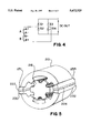
FIG. 8 is a cross-section of a machine similar to that of FIG. 6 except that a single auxiliary field winding F is employed according to a fifth embodiment of the present invention.
FIG. 9 is a cross section of a doubly salient machine similar to FIG. 2, except that one pair of permanent magnets of the embodiment of FIG. 2 has been replaced by auxiliary field windings F1 and F2.
FIG. 10 is a wiring diagram for the embodiment of the invention shown in FIG. 9 when operated as a generator.
DETAILED DESCRIPTION OF THE INVENTION
FIG. 1 shows a cross-section of a doubly salient stationary permanent magnet machine (SP2 M) according to one embodiment of the present invention. A stator 10 consists of a plurality of discrete laminated layers, each layer being punched to form a pair of yoke sections 11A, 11B, each section having two salient (or projecting) poles 12 positioned at angular intervals of π/2 radians. Each pole 12 has a pole arc θps of π/6 radians.
The rotor 16 also consists of a plurality of discrete laminated layers each of which are punched to form six salient poles 18 positioned at angular intervals θr of π/3. Each pole 18 also has a pole arc θpr equal to or slightly greater than π/6 radians.
The essential feature is that the total overlapping stator/rotor pole areas should preferably remain constant over 360° of rotation. This way, a constant reluctance is presented to the permanent magnet flux.
In the SP2 M embodiment of FIG. 1, stator 10 is wound with two short pitch windings A and B. Each short pitch winding (for example, the winding A) further comprises two short pitch coils A1 and A2 connected either in series or in parallel so that uniformity of the direction of current in the windings denoted by x's and •'s in FIG. 1 is maintained. The coils as exemplified by A1 and A2 of each winding are wound around a diametrically opposite pair of stator poles 12.
The winding arrangement yields the following exemplary alternating sequence during one complete revolution:
A-B-A-B-A
An essential feature of the embodiment of FIG. 1 comprises two permanent magnets 22 and 24 which are embedded inside the stator 10. The permanent magnets 22 and 24 may be incorporated without unduly increasing the overall motor size. The plurality of discrete laminated layers of stator 10 are each formed of similar punchings 11A and 11B, each having two salient poles 12, positioned with the poles 12 in facing relationship about the stator central axis. Preferably, permanent magnets 22 and 24 are parallelopipeds, and they may be formed by binding multiple smaller magnets into this shape. Magnets 22 and 24 are interposed between the ends of stator punchings 11A and 11B and extend longitudinally along the stator axis. Magnets 22 and 24 are polarized transversely to the stator axis, with like polarities of each magnet facing in the same direction and contacting the same one of punchings 11A or 11B at opposite ends thereof. That is, the north poles of both magnets 22 and 24 face stator punchings 11A and the south poles of both magnets face stator punchings 11B. If desired, the polarities of both magnets may be reversed.
Since the permanent magnets 22 and 24 are stationary, the magnetic force between the stator 10 and permanent magnets 22 and 24 is great enough to hold the permanent magnets in position. Hence, any conventional fixative can be used to secure the permanent magnets 22 and 24.
The permanent magnets 22 and 24 generate the primary flux, and a secondary (armature reaction) flux is induced by the stator pole windings A and B. Due to their air-like permeability, permanent magnets 22 and 24 present a very high constant reluctance which blocks the circulation of the secondary flux through the stator 10.
The particular stator pole 12 and rotor pole 18 arrangement of the present invention ensures that the total overlapped pole area remains constant for all positions of rotor 16. This way, the total air-gap reluctance (which is the primary reluctance for the permanent magnet excitation) is invariant to rotor 16 displacement θd, and there exists a substantially linear transfer of permanent magnet flux between adjacent stator poles 12 during rotation of rotor 16. Consequently, permanent magnets 22 and 24 produce no cogging torque at no load.
Since torque is produced as a result of the change of flux linkage in the active stator winding(s) A-B, there is a reaction torque component caused by the interaction of stator winding current and the permanent magnet flux, and there is a reluctance torque component caused by the variation in the reluctance of the magnetic path of the winding A-B. Hence, the present invention works on the variable reluctance principle as well as permanent magnet brushless DC motor principles.
In co-pending application Ser. No. 07/926,765 the ratio of stator poles to rotor poles is inverted as compared to the present invention. In the machine described therein, the stator is equipped with six salient poles wound for three phases and the rotor includes four salient poles. The machine operates in such a manner that only two of the three phases are carrying current at any time. Hence, only 2/3 of the copper of the machine can be considered as "active" at any instant of time.
In the present invention, as embodied in FIG. 1, however, both phases are carrying current at every time instant (except for the brief instants when the current reverses polarity). Hence, it can be accurately said that all of the copper is active at any instant, resulting in an improved utilization of copper within the machine compared to the machine of application Ser. No. 07/926,765.
In the present invention, any multiple of 4/6 stator/rotor poles may be used. For instance, FIG. 2 illustrates the basic structure for a machine incorporating a stator 110 having eight poles and a rotor 116 having twelve poles. The number of permanent magnets is multiplied accordingly, and four such magnets 121-124 are employed in the embodiment of FIG. 2 allowing magnets to be placed in all four corners of the stator. Four similar stator sections 111A-111D, each having two salient poles 112 are used in the embodiment of FIG. 2. The magnets 121-124 are polarized transversely to the central axis of the machine and the magnet faces abutting the opposite ends of each of sections 111A-111D are of like polarity. That is, the faces of magnets 121 and 124 abutting the opposite ends of sections 111A are both north poles and the faces of magnets 121 and 122 abutting opposite ends of sections 111B are both south poles, etc. Each of the stator poles 112 is wound with a coil A1-A4 and B1-B4 and the coils of diametrically opposed stator poles are connected together to form four windings, i.e., A1-A2, A3-A4, B1-B2, and B3-B4.
The principle could be extended to machine with an even higher number of stator poles by utilizing a hexagonally shaped stator and so forth. Alternatively, if desired, a stator with the usual circular outer shape could be used without serious loss of torque producing capability.
As seen in FIG. 3, the flux linkage λa and λb of each stator pole 12 increases at a constant rate for continuing rotor 16 displacement θd until full alignment of a diametric pair of stator poles 12 and rotor poles 18. Past alignment, the flux linkages λA and λB of the respective pole pairs decrease at a constant rate.
In the preferred mode of operation as a generator, positive current flows from a given phase when the magnetic flux linking that phase is increasing, and flows into the phase when the magnetic flux is decreasing. For either motoring or generating, each stator winding A, B, etc., typically defines one phase, and each stator winding is coiled about two diametrically opposed stator poles 12. For instance, the SP2 M of FIG. 1 is driven as a two-phase machine in which the two stator windings A and B define two phases. However many phases, the doubly-salient structure of the machine allows the production of positive torque over the entire area of overlap of an active stator pole 12 and rotor pole 18 pair. This essentially doubles the torque production when compared with a conventional VRM which can only produce torque while the phase inductance is increasing.
The armature reaction field energy Wf, which is to be recovered during current commutation, is greatly reduced because of the much smaller value of the stator 10 inductance. Therefore, the energy ratio, or equivalently, the power factor is very high. The smaller value of the stator inductance also makes the dynamic response of the motor much faster. Specifically, the stator windings A and B meet small permeances at both aligned and unaligned positions, even though a great deal of permanent magnet flux concentration is achieved under the overlapped pole pairs where electromagnetic torque is produced. As a result, the active stator phase winding will experience very small turn-on and turn-off inductances, thereby facilitating short commutation periods upon turn-on and turn-off.
Since the machine of the present invention is endowed with a small turn-off inductance Lp at the aligned pole position, the current in the active winding can decay to zero rapidly after the winding is turned off. It can also be seen in FIG. 3 that the inductance Lp is decreasing after the rotor poles pass the half overlapped position. Hence, the back emf due to the variation of the inductance reverses polarity after the half overlapped position. This reversal of polarity actually assists in the current reversal process because the back emf due to the inductance Lp variation now adds algebraically to the applied voltage before the active winding is turned off. Therefore, it is always possible to power the motor of the present invention using a conventional bi-directional (or bi-polar) converter as well as a conventional unidirectional converter.
Control of the invention can be accomplished in the same manner as a conventional variable reluctance motor, i.e., four quadrant operation is easily achieved by changing the sequence of conduction and the direction of current.
The preferred mode of operation of the present invention is as a generator. DC generator operation may be accomplished using the embodiment of FIG. 1 and a switched converter circuit as shown in FIG. 4. The converter employs a switched solid state bridge having two switch legs, each leg further comprising a pair of series-connected switch devices S1 & S2, S3 & S4. Switch devices S1-S4 may be any suitable gated devices such as diodes, transistors, thyristors, etc. or any combination of these switch devices. The two stator windings A and B are connected in series, with opposite polarities, as a single phase between the switch devices S1 & S2, S3 & S4 of each leg. In operation, the machine is driven to induce current waveforms in the stator windings A and B which are substantially as shown in FIG. 3. The switch devices S1-S4 of FIG. 4 are normally switched in pairs S1 & S4 and S2 & S3, one pair being switched "on" and one pair "off" in an alternating sequence of 30° intervals (as shown in lines A and B of FIG. 3) to convert the otherwise pulsed output to a rectified DC level.
FIG. 5 illustrates a cross-section of an embodiment of the present invention which has a smaller aspect ratio, i.e., the ratio of the outer diameter of the motor divided by the length. The aspect ratio is smaller because the square-shaped stator of FIG. 1 is replaced with a rounded stator 210. A rotor 216 is similar to the rotor 16 of FIG. 1. As shown in FIG. 5, the permanent magnets 222 and 224 are each sandwiched between two pieces of laminated steel insets 230-233. The steel insets 230-233 are mounted in the stator 210 and extend to the end region of the stator 210. This way, the permanent magnet flux is concentrated into the stator 210 through the respective pairs of laminated steel insets 230 and 231 and 232 and 233. The operation of the embodiment shown in FIG. 5 is in all other respects the same as that described above with respect to FIG. 1.
The advantage of the embodiment shown in FIG. 5 is that the volume of the motor can be reduced. However, a trade-off may occur because the manufacturing cost may be higher.
FIG. 6 shows a cross-section of a doubly salient machine according to another embodiment of the present invention. The machine comprises a stator 310 having four salient poles 312A-312D and a rotor 316 having six salient poles 318. Two phase windings A and B comprising coils A1 -A2 and B1 -B2 are wound about the stator poles 312, as in FIG. 1. The permanent magnets of the embodiment of FIG. 1 have been replaced by a pair of auxiliary field windings F1 and F2. Auxiliary field windings F1 and F2 are both coiled around the wall of the stator core 310 at diametrically opposite locations. Windings F1 and F2 are excited by a current IDC and are polarized so that the flux generated by each winding is in the same direction, as indicated by the arrows. Poles 312A and 312B are thereby polarized as north magnetic poles while poles 312C and 312D are south magnetic poles.
For motoring operation, a conventional switched converter circuit may be used. For generator operation, a switched converter circuit as shown in FIG. 7 may be employed. The converter employs a switched diode bridge having two switch legs, each leg further comprising a pair of series-connected switch devices S1 & S2, S3 & S4. The two stator windings A and B are connected in series, opposite polarities, as a single phase between the switch devices S1 & S2, S3 & S4 of each leg. In both cases of motoring and generating, the two field windings F1 and F2 are connected in series, same polarities, and are excited by a DC current IDC. Alternatively, the two field windings could be connected in parallel so that positive current is again into the dots of both windings noted in FIG. 7. This DC excitation accomplishes the same function as permanent magnets, namely, it provides the stator with excitation (i.e. field) flux thereby allowing for the development of a reaction torque or an induced voltage. The field current times the number of field turns is typically adjusted to such a value to as to mildly saturate the magnetic circuit made up of the stator core, the rotor core and the overlapping stator and rotor poles.
FIG. 8 is a cross-section of an alternative embodiment of the doubly salient machine with a single auxiliary field winding F according to the present invention. The machine is similar to the embodiment of FIG. 6 except that the two auxiliary field windings F1 and F2 of FIG. 6 are replaced by a single auxiliary field winding F. The auxiliary field winding F is coiled about the inner periphery of the stator 310 core on diametrically opposite sides. The field winding F, excited by a DC current IDC in the direction shown, generates flux for magnetizing poles 312A and 312B as north magnetic poles and poles 312c and 312D as south magnetic poles. Alternatively, the machine could be equipped with both the permanent magnet arrangement of FIG. 1 and either field coil arrangement of FIG. 7 or 8. In this case the field coil can be used to either reinforce the permanent magnet (field strengthening) or to oppose the magnet field (field weakening). The field strengthening is particularly advantageous when high torque (or high current) is required near zero speed, while field weakening is important when the machine operates beyond is normal speed range. The field strengthening and weakening capability can also be used to regulate the terminal voltage when operated as a generator.
FIG. 9 is a cross-section of another embodiment of the invention which combines the features of the machine using permanent magnets as in FIG. 2 and the machine using an electromagnetic excitation winding as in FIG. 6. The machine shown in FIG. 9 has two diametrically positioned permanent magnets 422, 424; eight stator poles 412A-412H and twelve rotor poles 418. The machine is wound with two phase windings A and B comprising coils A1 -A4 and B1 -B4 wound on separate stator poles and connected together as shown in FIG. 10. The stator 410 comprises similar yoke sections 411A, 411B, 411D, 411E, each having a single stator salient pole 412, together with similar yoke sections 411C and 411F, each having two stator salient poles. Yoke sections 411A-411F are arranged symmetrically about the rotor 418'. Permanent magnet 422 is embedded in the stator 410 at the adjacent ends of yoke sections 411A and 411B. Diametrically opposite from magnet 422, magnet 424 is embedded in the stator at the adjacent ends of yoke sections 411D and 411E. Auxiliary field windings F3 and F4 are wound longitudinally around yoke sections 411F and 411C, similarly to windings F1 and F2 of FIG. 6. Windings F3 and F4 are preferably located in a plane that is perpendicular to the plane containing magnets 422 and 424. Flux barriers 30 composed of non-magnetic material are interposed in stator 410 at the adjacent ends of yoke sections 411A-411F, 411B-411C, 411C-411D, and 411E-411F to prevent interaction between the magnets 422,424 and the windings F3, F4. In this embodiment windings A1, A2, B1 and B2 are linked by the flux of magnets 422, 424 and 424 while windings A3, A4, B3 and B4 are linked by the flux of field windings F3 and F4. With magnets 422 and 424 polarized as shown and with windings F1 and F2 fed with current IDC in the direction shown, stator poles 412A, 412D, 412E and 412H are magnetized as north magnetic poles and stator poles 412B, 412C, 412E and 412G are magnetized as south magnetic poles.
FIG. 10 is a wiring diagram for the machine of FIG. 9 for operation as a single phase generator. The A windings are all connected in series with the same magnetic polarity as all of the B windings. The A windings and the B windings are then connected in series with opposite magnetic polarity. The field coils F1 and F2 are connected in series (or parallel) with the same magnetic polarity. In this embodiment, positive current of a controlled amount directed into the dotted end of winding F1 establishes flux of such polarity that the voltages induced in windings A3, A4, B3 and B4 are controlled and in phase with the voltages induced in windings A1, A2, B1 and B2 by the permanent magnets. Alternatively, the induced voltages in windings A3, A4, B3 and B4 can be made to be in phase opposition (opposite polarity) with the voltages in windings A1, A2, B1 and B2 when current into the field coils is reversed by supplying positive current of a controlled amount to the undotted end of winding F2. Hence, the induced voltages in the stator coils can be considered as having a constant, uncontrolled voltage (produced by the magnets) and also a controlled voltage (produced by the field coils). In particular, the controlled voltage portion of the induced voltage can be controlled to add to the uncontrolled portion when high torque is required as, for example, starting of a traction motor. On the other hand, the controlled voltage portion of the induced stator voltage can be made to subtract when it is desirable to maintain a constant terminal voltage, as for example, during the so-called field weakening, constant power mode of operation encountered in high speed operation of traction drives or electrical generators as well as many other industrial applications.
Having now fully set forth the preferred embodiments and certain modifications of the concept underlying the present invention, various other embodiments as well as certain variations and modifications of the embodiment herein shown and described will obviously occur to those skilled in the art upon becoming familiar with said underlying concept. It is to be understood, therefore, that within the scope of the appended claims, the invention may be practiced otherwise than as specifically set forth herein.

Claims (19)

We claim:
1. A permanent magnet machine comprising:
a rotor mounted for rotation about a central axis, said rotor further comprising,
a multiple of six salient rotor poles evenly spaced around said central axis and extending outward therefrom; and
a stator, said stator further comprising,
a yoke surrounding said rotor;
a multiple of four salient stator poles extending from said yoke toward said rotor, said stator poles being spaced at equal angular intervals around said yoke and being arranged with respect to said rotor poles to provide a constant air-gap reluctance during rotation of said rotor within said stator,
a plurality of stator windings each being individually coiled about two diametrically opposite stator poles; and
a plurality of permanent magnets embedded in said yoke, said magnets being spaced at equal angular intervals around said yoke and being polarized transversely to said central axis to serve as a source of primary flux for magnetizing the machine, said magnets also serving to create a reluctance for blocking the circulation of flux through said yoke.
2. A permanent magnet machine comprising;
rotor mounted for rotation about a central axis, said rotor further comprising,
multiple of six salient rotor poles evenly spaced around said central axis and extending outward therefrom; and
a stator, said stator further comprising,
a yoke surrounding said rotor;
a multiple of four salient stator poles extending from said yoke toward said rotor, said stator poles being spaced at equal angular intervals around said yoke and being arranged with respect to said rotor poles to provide a constant air-gap reluctance during rotation of said rotor within said stator,
a plurality of stator windings each being individually coiled about two diametrically opposite stator poles; and
a plurality of permanent magnets embedded in said yoke, said magnets being spaced at equal angular intervals around said yoke and being polarized transversely to said central axis to serve as a source of primary flux for magnetizing the machine, said magnets also serving to create a reluctance for blocking the circulation of flux through said yoke, wherein said yoke comprises a plurality of similar sections arranged symmetrically about said central axis, each of said sections having an equal portion of said stator salient poles thereon, and wherein one each of said plurality of permanent magnets is interposed between the ends of two adjacent ones of said yoke sections.
3. A machine as claimed in claim 2, wherein:
said yoke comprises two sections, each of said sections having two salient poles, and
said plurality of permanent magnets comprises two permanent magnets, one each of said magnets being interposed between adjacent ends of said two yoke sections, said magnets being polarized such that the like poles of said magnets face the same one of said yoke sections at opposite ends thereof.
4. A machine as claimed in claim 3, wherein:
said plurality of stator windings comprises two stator windings, each of said stator windings consisting of two coils connected together, each of said coils being wound about one of a pair of diametric stator poles, each of said stator windings being connected to a separate phase of a two-phase source of alternating current.
5. A machine as claimed in claim 3, wherein:
said plurality of stator windings comprises two stator windings, each of said stator windings consisting of two coils connected together, each of said coils being wound about one of a pair of diametric stator poles, and
converter means connected to said stator windings for converting the currents induced therein by rotation of said rotor to direct current.
6. A machine as claimed in claim 2, wherein:
said yoke comprises four sections, each of said sections having two salient poles, and
said plurality of permanent magnets comprises four permanent magnets, one each of said magnets being interposed between the ends of two adjacent ones of said yoke sections, said magnets being polarized such the poles of the magnets at the opposite ends of each of said yoke sections are of the same polarity.
7. A machine as claimed in claim 6, wherein said multiple of six rotor poles consists of twelve rotor poles.
8. A variable reluctance machine comprising:
a rotor mounted for rotation about a central axis, said rotor further comprising:
a multiple of six salient rotor poles evenly spaced around said central axis; and
a stator surrounding said rotor, said stator further comprising:
a yoke;
a multiple of four salient stator poles extending from said yoke toward said rotor, said stator poles being spaced at equal angular intervals around said central axis and being arranged with respect to said rotor poles to provide a constant air gap reluctance during rotation of said rotor within said stator,
a plurality of stator windings each being individually coiled about two diametrically opposite stator poles, and
at least one auxiliary winding wound along the length of said yoke on diametrically opposite sides of said yoke to serve as a source of primary excitation flux.
9. The variable reluctance machine of claim 8, wherein said at least one auxiliary winding comprises two auxiliary windings each wound around yoke at diametrically opposite positions, and with additionally, means for energizing said auxiliary windings with direct current such that the flux generated by each said auxiliary winding is polarized in the same direction.
10. A variable reluctance machine comprising:
a rotor mounted for rotation about a central axis, said rotor further comprising:
a multiple of twelve salient rotor poles evenly spaced around said central axis; and
a stator surrounding said rotor, said stator further comprising:
a yoke;
eight salient stator poles extending from said yoke toward said rotor, said stator poles being spaced at equal angular intervals around said central axis and being arranged with respect to said rotor poles to provide a constant air gap reluctance during rotation of said rotor within said stator,
a plurality of stator windings each being individually coiled about two diametrically opposite stator poles;
first and second permanent magnets imbedded in said yoke diametrically opposite from one another to provide a first portion of the excitation flux of said machine;
first and second auxiliary windings, said auxiliary windings each being wound about said yoke diametrically opposite one another and in a plane that is perpendicular to the plane containing said first and second magnets; and
means for energizing said first and second auxiliary windings from a direct current source to provide a second portion of the excitation flux of said machine.
11. A variable reluctance machine as claimed in claim 10, wherein said first and second auxiliary windings are energized such that the flux generated thereby is of a polarity aiding the flux generated by said first and second permanent magnets.
12. A variable reluctance machine as claimed in claim 10, wherein said first and second auxiliary windings are energized such that the flux generated thereby is of a polarity opposing the flux generated by said first and second permanent magnets.
13. A variable reluctance machine as claimed in claim 10, with additionally:
a plurality of flux barriers embedded in said yoke so as to create high reluctance regions in the magnetic circuit of said yoke to prevent interaction between said first and second permanent magnets and said first and second auxiliary windings.
14. A variable reluctance machine as claimed in claim 13, wherein;
said flux barriers each comprise a mass of non-magnetic material.
15. A variable reluctance machine as claimed in claim 14, wherein said plurality of flux barriers comprises four flux barriers;
a first one of said flux barriers being imbedded in said yoke medially between said first permanent magnet and said first auxiliary winding;
a second one of said flux barriers being imbedded in said yoke medially between said first permanent magnet and said second auxiliary winding;
a third one of said flux barriers being imbedded in said yoke medially between said second auxiliary winding and said second permanent magnet; and
a fourth one of said flux barriers being imbedded in said yoke medially between said second permanent magnet and said first auxiliary winding.
16. A variable reluctance machine comprising:
a rotor mounted for rotation about a central axis, said rotor further comprising:
a multiple of six salient rotor poles evenly spaced around said central axis; and
a stator surrounding said rotor, said stator further comprising:
a yoke;
a multiple of four salient stator poles extending from said yoke toward said rotor, said stator poles being spaced at equal angular intervals around said central axis and being arranged with respect to said rotor poles to provide a constant air gap reluctance during rotation of said rotor within said stator;
a plurality of stator windings each being individually coiled about two diametrically opposite stator poles;
at least two permanent magnets embedded in said yoke, said magnets being spaced at equal angular intervals around said yoke, and at least one auxiliary winding wound along the length of said yoke on diametrically opposite sides of said yoke, wherein said at least two permanent magnets and said at least one auxiliary winding serve as a source of primary excitation flux of said machine, said primary excitation flux including first and second portions, respectively;
wherein the machine further comprises means for energizing said at least one auxiliary winding from a direct current source to provide said second portion of the primary excitation flux of said machine; and
wherein said at least two permanent magnets serve as a source of said first portion of said primary excitation flux.
17. The variable reluctance machine of claim 16, wherein said at least one auxiliary winding comprises first and second auxiliary windings, each wound around yoke at diametrically opposite positions, and are energized such that the flux generated by each said first and second auxiliary windings is polarized in the same direction.
18. A variable reluctance machine as claimed in claim 16, wherein said at least one auxiliary winding is energized such that the flux generated thereby is of a polarity aiding the flux generated by said at least two permanent magnets.
19. A variable reluctance machine as claimed in claim 16, wherein said at least one auxiliary winding is energized such that the flux generated thereby is of a polarity opposing the flux generated by said at least two permanent magnets.
US08/514,495 1992-08-06 1995-08-11 Doubly salient variable reluctance machine with stationary permanent magnets or auxiliary field windings Expired - Fee Related US5672925A (en)

Priority Applications (3)

Application Number Priority Date Filing Date Title
US08/514,495 US5672925A (en) 1992-08-06 1995-08-11 Doubly salient variable reluctance machine with stationary permanent magnets or auxiliary field windings
AU55665/96A AU5566596A (en) 1995-08-11 1996-04-22 Doubly salient variable reluctance machine with stationary permanent magnets or auxiliary field windings
PCT/US1996/005618 WO1997007583A1 (en) 1995-08-11 1996-04-22 Doubly salient variable reluctance machine with stationary permanent magnets or auxiliary field windings

Applications Claiming Priority (2)

Application Number Priority Date Filing Date Title
US07/926,765 US5825112A (en) 1992-08-06 1992-08-06 Doubly salient motor with stationary permanent magnets
US08/514,495 US5672925A (en) 1992-08-06 1995-08-11 Doubly salient variable reluctance machine with stationary permanent magnets or auxiliary field windings

Related Parent Applications (1)

Application Number Title Priority Date Filing Date
US07/926,765 Continuation-In-Part US5825112A (en) 1992-05-11 1992-08-06 Doubly salient motor with stationary permanent magnets

Publications (1)

Publication Number Publication Date
US5672925A true US5672925A (en) 1997-09-30

Family

ID=24047419

Family Applications (1)

Application Number Title Priority Date Filing Date
US08/514,495 Expired - Fee Related US5672925A (en) 1992-08-06 1995-08-11 Doubly salient variable reluctance machine with stationary permanent magnets or auxiliary field windings

Country Status (3)

Country Link
US (1) US5672925A (en)
AU (1) AU5566596A (en)
WO (1) WO1997007583A1 (en)

Cited By (77)

* Cited by examiner, † Cited by third party
Publication number Priority date Publication date Assignee Title
US5866964A (en) * 1996-01-29 1999-02-02 Emerson Electric Company Reluctance machine with auxiliary field excitations
US5923142A (en) * 1996-01-29 1999-07-13 Emerson Electric Co. Low cost drive for switched reluctance motor with DC-assisted excitation
US6034460A (en) * 1996-04-12 2000-03-07 Hitachi, Ltd. Permanent magnet rotating electric machine and electrically driven vehicle employing same
US6051904A (en) * 1997-10-07 2000-04-18 Valeo Equipments Electriques Moteur Rotary electric machine, especially an alternator for a motor vehicle
US6133664A (en) * 1996-05-30 2000-10-17 Vilmos Torok Self-starting brushless electric motor
US6140731A (en) * 1996-05-30 2000-10-31 Vilmos Trorok Self-starting brushless electric motor
US6242834B1 (en) * 1997-04-14 2001-06-05 Valeo Equipements Electriques Moteur Brushless polyphase machine, in particular motor vehicle alternator
US6342746B1 (en) * 1998-07-31 2002-01-29 Magnetic Revolutions Limited, L.L.C. Methods for controlling the path of magnetic flux from a permanent magnet and devices incorporating the same
US20020084716A1 (en) * 2001-01-04 2002-07-04 Harter Bernard G. End cap assembly for a switched reluctance electric machine
US20020093269A1 (en) * 2001-01-16 2002-07-18 Harter Bernard G. Slot area undercut for segmented stators
EP1236269A1 (en) 1999-12-06 2002-09-04 Lucas Industries Limited Switched reluctance generator and a method of controlling such a generator
WO2002097954A1 (en) * 2001-05-31 2002-12-05 Robert Bosch Gmbh Two-phase, switched reluctance motor
US6584813B2 (en) 2001-03-26 2003-07-01 Emerson Electric Co. Washing machine including a segmented stator switched reluctance motor
US20030122440A1 (en) * 2001-12-28 2003-07-03 Emerson Electric Co. Doubly salient machine with permanent magnets in stator teeth
US6628034B2 (en) * 2001-03-30 2003-09-30 Hanyang Hak Won Co., Ltd. Brushless DC motor with armature windings compensated by auxiliary windings
US6700284B2 (en) 2001-03-26 2004-03-02 Emerson Electric Co. Fan assembly including a segmented stator switched reluctance fan motor
US6724114B2 (en) 2001-12-28 2004-04-20 Emerson Electric Co. Doubly salient machine with angled permanent magnets in stator teeth
US6777844B2 (en) 2000-10-24 2004-08-17 Rexair, Inc. Brushless motor
US20040239199A1 (en) * 2003-05-30 2004-12-02 Wisconsin Alumni Research Foundation Dual-rotor, radial-flux, toroidally-wound, permanent-magnet machine
US20050023917A1 (en) * 2001-12-21 2005-02-03 Bsh Bosch Und Siemens Hausgerate Gmbh Electric motor and method for producing the motor
US6864608B2 (en) * 2001-07-31 2005-03-08 Korea Electrotechnology Research Institute Brushless generator with permanent magnets
US6897591B2 (en) * 2001-03-26 2005-05-24 Emerson Electric Co. Sensorless switched reluctance electric machine with segmented stator
US20050122074A1 (en) * 2003-06-12 2005-06-09 Mcmillan Electric Company Single coil, direct current permanent magnet brushless motor with voltage boost
US20050156475A1 (en) * 2002-05-24 2005-07-21 Virginia Tech Intellectual Properties, Inc. PMBDCM and two phase SRM motor, two phase SRM rotor and stator, and coil wrap for PMBDCM and SRM motors
US20050179413A1 (en) * 2004-02-17 2005-08-18 Visteon Global Technologies, Inc. System for controlling motor speed by altering magnetic field of the motor
US20050178366A1 (en) * 2004-02-17 2005-08-18 Visteon Global Technologies, Inc. Fuel system with a field modification module for controlling fuel flow
US7012350B2 (en) * 2001-01-04 2006-03-14 Emerson Electric Co. Segmented stator switched reluctance machine
US20060226725A1 (en) * 2004-10-27 2006-10-12 Magnetic Torque International Ltd. Multivariable generator and method of using the same
EP1717947A2 (en) * 2005-04-01 2006-11-02 LG Electronics Inc. Switched reluctance generator with improved generation efficiency in low-speed range
US20060273681A1 (en) * 2002-12-10 2006-12-07 Tri-Seven Research, Inc. Starting system for salient-poled-rotor electric motor
WO2007022139A1 (en) * 2005-08-12 2007-02-22 Power Group International, Inc. Self-regulated permanent magnet generator
US7233088B2 (en) 2003-01-17 2007-06-19 Magnetic Torque International, Ltd. Torque converter and system using the same
US7250734B1 (en) * 2003-05-27 2007-07-31 Synchrony, Inc. High performance switched reluctance machine
US7268454B2 (en) 2003-01-17 2007-09-11 Magnetic Torque International, Ltd. Power generating systems
WO2007113651A2 (en) * 2006-04-04 2007-10-11 Toyota Jidosha Kabushiki Kaisha Motor and electric power supply control apparatus for the motor
US20080272664A1 (en) * 2007-03-27 2008-11-06 Flynn Charles J Permanent magnet electro-mechanical device providing motor/generator functions
CN100438280C (en) * 2006-08-23 2008-11-26 南京航空航天大学 Tangential magnetic steel double-convex pole hybrid excitation motor
US20080290764A1 (en) * 2007-05-22 2008-11-27 Halsey David G Electrodynamic machine control
CN100444502C (en) * 2006-04-07 2008-12-17 东南大学 Full range distribution winding and doubly salient permanent magnet motor with auxiliary exciting winding
WO2009000162A1 (en) * 2007-06-27 2008-12-31 Shizheng He A refrigerant compressor
US20090102303A1 (en) * 2006-02-01 2009-04-23 Ansgar Ackva Electric Motor
GB2454171A (en) * 2007-10-29 2009-05-06 Technelec Ltd Reluctance machines or the inductor type with permanent magnets integrated into the stator
US20090115265A1 (en) * 2007-11-07 2009-05-07 Technofan Motor for an aeronautical fan
US20090146430A1 (en) * 2007-12-10 2009-06-11 Walter Edmond Sear Tidal/water current electrical generating system
US20090160391A1 (en) * 2007-03-07 2009-06-25 Flynn Charles J Hybrid permanent magnet motor
US20090322290A1 (en) * 2008-06-27 2009-12-31 Shah Mahesh J Regulated hybrid permanent magnet generator
US20100038978A1 (en) * 2006-03-08 2010-02-18 Gemplus Flux-switching dual excitation electrical machine
US20100141061A1 (en) * 2007-05-31 2010-06-10 Krishnan Ramu Switched Reluctance Machines with Minimum Stator Core
CN101127461B (en) * 2007-07-13 2010-09-08 南京航空航天大学 Mixed excitation dual protruding pole brushless DC generator
US20110089775A1 (en) * 2009-10-19 2011-04-21 Qm Power, Inc. Parallel Magnetic Circuit Motor
US20120306296A1 (en) * 2011-06-02 2012-12-06 Samsung Electro-Mechanics Co., Ltd. Switched reluctance motor
US8450963B2 (en) 2010-10-11 2013-05-28 Wisconsin Alumni Research Foundation Brushless synchronous machine utilizing third harmonic excitation
US20130134805A1 (en) * 2011-11-29 2013-05-30 Samsung Electro-Mechanics Co., Ltd. Switched reluctance motor
JP2013201869A (en) * 2012-03-26 2013-10-03 Denso Corp Rotary machine
US20140203754A1 (en) * 2013-01-24 2014-07-24 Rolls-Royce Plc Method of controlling an ac machine and controller for controlling an ac machine
US20140265709A1 (en) * 2013-03-13 2014-09-18 Arizona Digital, Inc. Steered Flux Generator
CN104600944A (en) * 2014-06-23 2015-05-06 深圳市乐丰科技有限公司 Permanent magnet switch reluctance machine and a stator assembly thereof
US20150295456A1 (en) * 2012-11-20 2015-10-15 Jaguar Land Rover Limited Electric machine and method of operation thereof
CN105340156A (en) * 2013-02-01 2016-02-17 法雷奥空气管理英国有限公司 A stator assembly for an electric supercharger
US20160248308A1 (en) * 2013-12-25 2016-08-25 Mitsubishi Electric Corporation Magnetic inductor electric motor and manufacturing method therefor
WO2017013674A1 (en) * 2015-07-22 2017-01-26 Sankar Hazra An efficient induction motor
US9956050B2 (en) 2016-08-16 2018-05-01 Ethicon Endo-Surgery, Llc Methods, systems, and devices for controlling a motor of a robotic surgical system
US9968412B2 (en) 2016-08-16 2018-05-15 Ethicon Endo-Surgery, Llc Methods, systems, and devices for controlling a motor of a robotic surgical system
US10016246B2 (en) * 2016-08-16 2018-07-10 Ethicon Llc Methods, systems, and devices for controlling a motor of a robotic surgical system
US10372045B2 (en) * 2012-09-19 2019-08-06 Asml Netherlands B.V. Method of calibrating a reluctance actuator assembly, reluctance actuator and lithographic apparatus comprising such reluctance actuator
US10396615B2 (en) 2013-02-28 2019-08-27 General Electric Company Electric machine stator lamination with dual phase magnetic material
US10491055B2 (en) 2017-06-27 2019-11-26 Hamilton Sundstrand Corporation Self-exciting synchronous reluctance generators
CN111279588A (en) * 2017-09-25 2020-06-12 三菱重工发动机和增压器株式会社 Pressure booster
US10731627B1 (en) 2019-10-07 2020-08-04 Timm A Vanderelli Low wind generator with internal rechargeable power
US10892664B2 (en) * 2017-09-14 2021-01-12 Rolls-Royce Plc Segmented electrical machine
US10944302B2 (en) 2018-04-09 2021-03-09 Williams International Co., L.L.C. Permanent-magnet generator incorporating a variable-reluctance stator system
US11075572B2 (en) * 2017-04-05 2021-07-27 Kone Corporation Linear flux switching permanent magnet motor
US20220029511A1 (en) * 2019-04-18 2022-01-27 Samsung Electronics Co., Ltd. Drive motor and vacuum cleaner having the same
US11411444B2 (en) 2020-07-20 2022-08-09 Lin Engineering, Inc. Variable reluctance step motor having enhanced holding torque
EP4012904A4 (en) * 2019-08-07 2022-08-24 Omir Karimovitch Bayaliev Bayaliev universal generator/motor
US11661646B2 (en) 2021-04-21 2023-05-30 General Electric Comapny Dual phase magnetic material component and method of its formation
US11926880B2 (en) 2021-04-21 2024-03-12 General Electric Company Fabrication method for a component having magnetic and non-magnetic dual phases

Families Citing this family (3)

* Cited by examiner, † Cited by third party
Publication number Priority date Publication date Assignee Title
BR9815420A (en) * 1997-11-28 2001-07-17 Abb Ab Method and device for controlling the magnetic flux with an auxiliary winding on a rotating high voltage alternating current machine
GB2428902B (en) * 2005-08-03 2009-04-01 Imra Europ S A S Uk Res Ct Salient pole electrical machine
DE102013113204A1 (en) * 2013-11-28 2015-05-28 Pierburg Gmbh Actuator for units in a motor vehicle

Citations (25)

* Cited by examiner, † Cited by third party
Publication number Priority date Publication date Assignee Title
US2539569A (en) * 1948-09-02 1951-01-30 Dudley B Clark Acyclic generator
US2816240A (en) * 1956-03-09 1957-12-10 American Mach & Foundry High speed composite electro-magnet and permanent magnet generator
US3616761A (en) * 1968-07-16 1971-11-02 Alberto Serra Valls Homopolar locomotive railway
US3783502A (en) * 1971-09-16 1974-01-08 Gen Electric Method of making high speed homopolar generator with straight winding construction
US3862445A (en) * 1973-03-05 1975-01-21 Siemens Ag Stator structure for permanent magnet excited machines
US3984711A (en) * 1975-04-07 1976-10-05 Warner Electric Brake & Clutch Company Variable reluctance step motor with permanent magnets
US4011479A (en) * 1974-12-20 1977-03-08 Siemens Aktiengesellschaft Stator construction for a permanent magnet-excited d-c machine
US4081703A (en) * 1976-05-26 1978-03-28 North American Philips Corporation Electric motor having toothed pole pieces
US4097754A (en) * 1976-10-20 1978-06-27 Tecumseh Products Company Short pitch alternator
US4110646A (en) * 1976-10-05 1978-08-29 Bogue Electric Manufacturing Company AC synchronous motor having an axially laminated rotor
US4217513A (en) * 1976-11-10 1980-08-12 Fujitsu Fanuc Limited Direct current motor
US4348605A (en) * 1979-03-30 1982-09-07 Asea Aktiebolag Electrical reluctance machine
US4472651A (en) * 1983-09-22 1984-09-18 General Electric Company Permanent magnet rotor
US4629921A (en) * 1982-09-14 1986-12-16 Gavaletz John S Dynamoelectric machine rotor
US4631510A (en) * 1985-09-03 1986-12-23 Powerton, Division Of Contraves Goerz Corporation Harmonically graded airgap reluctance-type rotating electric resolver
US4712028A (en) * 1984-05-21 1987-12-08 Sigma Instruments, Inc. Magnetically assisted stepping motor
US4733117A (en) * 1987-04-27 1988-03-22 The Superior Electric Company Reluctance synchro/resolver
US4752707A (en) * 1986-02-06 1988-06-21 Morrill Wayne J Three-phase, one-third pitch motor
US4916346A (en) * 1987-12-28 1990-04-10 General Electric Company Composite rotor lamination for use in reluctance hompolar, and permanent magnet machines
US4939398A (en) * 1986-10-06 1990-07-03 Emerson Electric Co. Laminated assemblies with in situ molded magnets
US5051640A (en) * 1989-04-27 1991-09-24 Siemens Aktiengesellschaft Heteropolar excited synchronous machine
US5059884A (en) * 1990-04-10 1991-10-22 Sundstrand Corporation Variable reluctance motor providing holding torque
US5117144A (en) * 1988-08-25 1992-05-26 Toeroek Vilmos Electric motor
US5304882A (en) * 1992-05-11 1994-04-19 Electric Power Research Institute, Inc. Variable reluctance motors with permanent magnet excitation
US5455473A (en) * 1992-05-11 1995-10-03 Electric Power Research Institute, Inc. Field weakening for a doubly salient motor with stator permanent magnets

Patent Citations (26)

* Cited by examiner, † Cited by third party
Publication number Priority date Publication date Assignee Title
US2539569A (en) * 1948-09-02 1951-01-30 Dudley B Clark Acyclic generator
US2816240A (en) * 1956-03-09 1957-12-10 American Mach & Foundry High speed composite electro-magnet and permanent magnet generator
US3616761A (en) * 1968-07-16 1971-11-02 Alberto Serra Valls Homopolar locomotive railway
US3783502A (en) * 1971-09-16 1974-01-08 Gen Electric Method of making high speed homopolar generator with straight winding construction
US3862445A (en) * 1973-03-05 1975-01-21 Siemens Ag Stator structure for permanent magnet excited machines
US4011479A (en) * 1974-12-20 1977-03-08 Siemens Aktiengesellschaft Stator construction for a permanent magnet-excited d-c machine
US3984711A (en) * 1975-04-07 1976-10-05 Warner Electric Brake & Clutch Company Variable reluctance step motor with permanent magnets
US4081703A (en) * 1976-05-26 1978-03-28 North American Philips Corporation Electric motor having toothed pole pieces
US4110646A (en) * 1976-10-05 1978-08-29 Bogue Electric Manufacturing Company AC synchronous motor having an axially laminated rotor
US4097754A (en) * 1976-10-20 1978-06-27 Tecumseh Products Company Short pitch alternator
US4217513A (en) * 1976-11-10 1980-08-12 Fujitsu Fanuc Limited Direct current motor
US4348605A (en) * 1979-03-30 1982-09-07 Asea Aktiebolag Electrical reluctance machine
US4629921A (en) * 1982-09-14 1986-12-16 Gavaletz John S Dynamoelectric machine rotor
US4472651A (en) * 1983-09-22 1984-09-18 General Electric Company Permanent magnet rotor
US4712028A (en) * 1984-05-21 1987-12-08 Sigma Instruments, Inc. Magnetically assisted stepping motor
US4827164A (en) * 1984-05-21 1989-05-02 Pacific Scientific Company Magnetically assisted stepping motor
US4631510A (en) * 1985-09-03 1986-12-23 Powerton, Division Of Contraves Goerz Corporation Harmonically graded airgap reluctance-type rotating electric resolver
US4752707A (en) * 1986-02-06 1988-06-21 Morrill Wayne J Three-phase, one-third pitch motor
US4939398A (en) * 1986-10-06 1990-07-03 Emerson Electric Co. Laminated assemblies with in situ molded magnets
US4733117A (en) * 1987-04-27 1988-03-22 The Superior Electric Company Reluctance synchro/resolver
US4916346A (en) * 1987-12-28 1990-04-10 General Electric Company Composite rotor lamination for use in reluctance hompolar, and permanent magnet machines
US5117144A (en) * 1988-08-25 1992-05-26 Toeroek Vilmos Electric motor
US5051640A (en) * 1989-04-27 1991-09-24 Siemens Aktiengesellschaft Heteropolar excited synchronous machine
US5059884A (en) * 1990-04-10 1991-10-22 Sundstrand Corporation Variable reluctance motor providing holding torque
US5304882A (en) * 1992-05-11 1994-04-19 Electric Power Research Institute, Inc. Variable reluctance motors with permanent magnet excitation
US5455473A (en) * 1992-05-11 1995-10-03 Electric Power Research Institute, Inc. Field weakening for a doubly salient motor with stator permanent magnets

Cited By (122)

* Cited by examiner, † Cited by third party
Publication number Priority date Publication date Assignee Title
US5923142A (en) * 1996-01-29 1999-07-13 Emerson Electric Co. Low cost drive for switched reluctance motor with DC-assisted excitation
US5866964A (en) * 1996-01-29 1999-02-02 Emerson Electric Company Reluctance machine with auxiliary field excitations
US6396183B1 (en) * 1996-04-12 2002-05-28 Hitachi, Ltd. Permanent magnet rotating electric machine and electrically driven vehicle employing same
US6034460A (en) * 1996-04-12 2000-03-07 Hitachi, Ltd. Permanent magnet rotating electric machine and electrically driven vehicle employing same
US6140731A (en) * 1996-05-30 2000-10-31 Vilmos Trorok Self-starting brushless electric motor
US6133664A (en) * 1996-05-30 2000-10-17 Vilmos Torok Self-starting brushless electric motor
US6242834B1 (en) * 1997-04-14 2001-06-05 Valeo Equipements Electriques Moteur Brushless polyphase machine, in particular motor vehicle alternator
US6051904A (en) * 1997-10-07 2000-04-18 Valeo Equipments Electriques Moteur Rotary electric machine, especially an alternator for a motor vehicle
US6342746B1 (en) * 1998-07-31 2002-01-29 Magnetic Revolutions Limited, L.L.C. Methods for controlling the path of magnetic flux from a permanent magnet and devices incorporating the same
US20030020436A1 (en) * 1999-12-06 2003-01-30 Coles Jeffrey Ronald Switched reluctance generator and a method of controlling such a generator
EP1236269A1 (en) 1999-12-06 2002-09-04 Lucas Industries Limited Switched reluctance generator and a method of controlling such a generator
US6777844B2 (en) 2000-10-24 2004-08-17 Rexair, Inc. Brushless motor
US20020084716A1 (en) * 2001-01-04 2002-07-04 Harter Bernard G. End cap assembly for a switched reluctance electric machine
US7012350B2 (en) * 2001-01-04 2006-03-14 Emerson Electric Co. Segmented stator switched reluctance machine
US6744166B2 (en) 2001-01-04 2004-06-01 Emerson Electric Co. End cap assembly for a switched reluctance electric machine
US20020093269A1 (en) * 2001-01-16 2002-07-18 Harter Bernard G. Slot area undercut for segmented stators
US6584813B2 (en) 2001-03-26 2003-07-01 Emerson Electric Co. Washing machine including a segmented stator switched reluctance motor
US6700284B2 (en) 2001-03-26 2004-03-02 Emerson Electric Co. Fan assembly including a segmented stator switched reluctance fan motor
US6897591B2 (en) * 2001-03-26 2005-05-24 Emerson Electric Co. Sensorless switched reluctance electric machine with segmented stator
US6628034B2 (en) * 2001-03-30 2003-09-30 Hanyang Hak Won Co., Ltd. Brushless DC motor with armature windings compensated by auxiliary windings
WO2002097954A1 (en) * 2001-05-31 2002-12-05 Robert Bosch Gmbh Two-phase, switched reluctance motor
US6864608B2 (en) * 2001-07-31 2005-03-08 Korea Electrotechnology Research Institute Brushless generator with permanent magnets
US20050023917A1 (en) * 2001-12-21 2005-02-03 Bsh Bosch Und Siemens Hausgerate Gmbh Electric motor and method for producing the motor
US20030122440A1 (en) * 2001-12-28 2003-07-03 Emerson Electric Co. Doubly salient machine with permanent magnets in stator teeth
US6724114B2 (en) 2001-12-28 2004-04-20 Emerson Electric Co. Doubly salient machine with angled permanent magnets in stator teeth
US6777842B2 (en) 2001-12-28 2004-08-17 Emerson Electric Co. Doubly salient machine with permanent magnets in stator teeth
US20050156475A1 (en) * 2002-05-24 2005-07-21 Virginia Tech Intellectual Properties, Inc. PMBDCM and two phase SRM motor, two phase SRM rotor and stator, and coil wrap for PMBDCM and SRM motors
US7420308B2 (en) * 2002-05-24 2008-09-02 Virginia Tech Intellectual Properties, Inc. PMBDCM and two phase SRM motor, two phase SRM rotor and stator, and coil wrap for PMBDCM and SRM motors
US20060273681A1 (en) * 2002-12-10 2006-12-07 Tri-Seven Research, Inc. Starting system for salient-poled-rotor electric motor
US7583000B2 (en) * 2002-12-10 2009-09-01 Tri-Seven Research, Inc. Starting system for salient-poled-rotor electric motor
US7608961B2 (en) 2003-01-17 2009-10-27 Magnetic Torque International, Ltd Torque converter and system using the same
US7687956B2 (en) 2003-01-17 2010-03-30 Magnetic Torque International, Ltd. Drive motor system
US7279819B2 (en) 2003-01-17 2007-10-09 Magnetic Torque International, Ltd. Power generating systems
US7342337B2 (en) 2003-01-17 2008-03-11 Magnetic Torque International, Ltd. Power generating systems
US7336011B2 (en) 2003-01-17 2008-02-26 Magnetic Torque International Ltd. Power generating systems
US7312548B2 (en) 2003-01-17 2007-12-25 Magnetic Torque International, Ltd. Torque converter and system using the same
US7268454B2 (en) 2003-01-17 2007-09-11 Magnetic Torque International, Ltd. Power generating systems
US7233088B2 (en) 2003-01-17 2007-06-19 Magnetic Torque International, Ltd. Torque converter and system using the same
US7279818B1 (en) 2003-01-17 2007-10-09 Magnetic Torque International Ltd. Power generating systems
US7250734B1 (en) * 2003-05-27 2007-07-31 Synchrony, Inc. High performance switched reluctance machine
US6924574B2 (en) 2003-05-30 2005-08-02 Wisconsin Alumni Research Foundation Dual-rotor, radial-flux, toroidally-wound, permanent-magnet machine
US20040239199A1 (en) * 2003-05-30 2004-12-02 Wisconsin Alumni Research Foundation Dual-rotor, radial-flux, toroidally-wound, permanent-magnet machine
US6940238B2 (en) * 2003-06-12 2005-09-06 Mcmillan Electric Company Single coil, direct current permanent magnet brushless motor with voltage boost
US20050122074A1 (en) * 2003-06-12 2005-06-09 Mcmillan Electric Company Single coil, direct current permanent magnet brushless motor with voltage boost
US20050179413A1 (en) * 2004-02-17 2005-08-18 Visteon Global Technologies, Inc. System for controlling motor speed by altering magnetic field of the motor
US7086838B2 (en) 2004-02-17 2006-08-08 Ford Motor Company Fuel system with a field modification module for controlling fuel flow
US7045983B2 (en) 2004-02-17 2006-05-16 Ford Motor Company System for controlling motor speed by altering magnetic field of the motor
US20050178366A1 (en) * 2004-02-17 2005-08-18 Visteon Global Technologies, Inc. Fuel system with a field modification module for controlling fuel flow
US7808142B2 (en) 2004-10-27 2010-10-05 E3 Solutions, Llc Multivariable generator and method of using the same
US20060226725A1 (en) * 2004-10-27 2006-10-12 Magnetic Torque International Ltd. Multivariable generator and method of using the same
EP1717947A3 (en) * 2005-04-01 2006-12-06 LG Electronics Inc. Switched reluctance generator with improved generation efficiency in low-speed range
CN1841915B (en) * 2005-04-01 2011-01-19 Lg电子株式会社 Switched reluctance generator with improved generation efficiency in low-speed range
EP1717947A2 (en) * 2005-04-01 2006-11-02 LG Electronics Inc. Switched reluctance generator with improved generation efficiency in low-speed range
WO2007022139A1 (en) * 2005-08-12 2007-02-22 Power Group International, Inc. Self-regulated permanent magnet generator
CN101288218B (en) * 2005-08-12 2010-12-22 电源组国际公司 Self-regulated permanent magnet generator
AU2006279600B2 (en) * 2005-08-12 2010-09-16 Power Group International, Inc. Self-regulated permanent magnet generator
US20090102303A1 (en) * 2006-02-01 2009-04-23 Ansgar Ackva Electric Motor
US8008824B2 (en) * 2006-02-01 2011-08-30 Brose Fahrzeugteile Gmbh & Co. Kommanditgesellschaft, Wuerzburg Electric motor
US20100038978A1 (en) * 2006-03-08 2010-02-18 Gemplus Flux-switching dual excitation electrical machine
US7868506B2 (en) * 2006-03-08 2011-01-11 Centre National De La Recherche Scientifique (Cnrs) Flux-switching dual excitation electrical machine
CN101416372B (en) * 2006-04-04 2012-07-18 丰田自动车株式会社 Motor and power supply control device for the same
WO2007113651A2 (en) * 2006-04-04 2007-10-11 Toyota Jidosha Kabushiki Kaisha Motor and electric power supply control apparatus for the motor
US7868505B2 (en) 2006-04-04 2011-01-11 Toyota Jidosha Kabushiki Kaisha Motor and electric power supply control apparatus for the motor
US20100170741A1 (en) * 2006-04-04 2010-07-08 Toyota Jidosha Kabushiki Kaisha Motor and electric power supply control apparatus for the motor
WO2007113651A3 (en) * 2006-04-04 2008-06-05 Toyota Motor Co Ltd Motor and electric power supply control apparatus for the motor
KR101004278B1 (en) * 2006-04-04 2011-01-03 도요타 지도샤(주) Motor and electric power supply control apparatus for the motor
CN100444502C (en) * 2006-04-07 2008-12-17 东南大学 Full range distribution winding and doubly salient permanent magnet motor with auxiliary exciting winding
CN100438280C (en) * 2006-08-23 2008-11-26 南京航空航天大学 Tangential magnetic steel double-convex pole hybrid excitation motor
US20090160391A1 (en) * 2007-03-07 2009-06-25 Flynn Charles J Hybrid permanent magnet motor
US7898135B2 (en) * 2007-03-07 2011-03-01 Qm Power, Inc. Hybrid permanent magnet motor
US20080272664A1 (en) * 2007-03-27 2008-11-06 Flynn Charles J Permanent magnet electro-mechanical device providing motor/generator functions
US7782007B2 (en) 2007-05-22 2010-08-24 Hamilton Sundstrand Corporation Electrodynamic machine control
US20080290764A1 (en) * 2007-05-22 2008-11-27 Halsey David G Electrodynamic machine control
US20100141061A1 (en) * 2007-05-31 2010-06-10 Krishnan Ramu Switched Reluctance Machines with Minimum Stator Core
US8901798B2 (en) * 2007-05-31 2014-12-02 Regal Beloit America, Inc. Switched reluctance machines with minimum stator core
WO2009000162A1 (en) * 2007-06-27 2008-12-31 Shizheng He A refrigerant compressor
CN101127461B (en) * 2007-07-13 2010-09-08 南京航空航天大学 Mixed excitation dual protruding pole brushless DC generator
GB2454171A (en) * 2007-10-29 2009-05-06 Technelec Ltd Reluctance machines or the inductor type with permanent magnets integrated into the stator
GB2454171B (en) * 2007-10-29 2012-05-23 Technelec Ltd Reluctance machines with permanent magnets integrated into the stator
FR2923330A1 (en) * 2007-11-07 2009-05-08 Technofan Sa MOTOR FOR AERONAUTICAL FAN.
US20090115265A1 (en) * 2007-11-07 2009-05-07 Technofan Motor for an aeronautical fan
US20090146430A1 (en) * 2007-12-10 2009-06-11 Walter Edmond Sear Tidal/water current electrical generating system
US8148866B2 (en) * 2008-06-27 2012-04-03 Hamilton Sundstrand Corporation Regulated hybrid permanent magnet generator
US20090322290A1 (en) * 2008-06-27 2009-12-31 Shah Mahesh J Regulated hybrid permanent magnet generator
US20110089775A1 (en) * 2009-10-19 2011-04-21 Qm Power, Inc. Parallel Magnetic Circuit Motor
US10340778B2 (en) * 2009-10-19 2019-07-02 Qm Power, Inc. Parallel magnetic circuit motor
US8450963B2 (en) 2010-10-11 2013-05-28 Wisconsin Alumni Research Foundation Brushless synchronous machine utilizing third harmonic excitation
US20120306296A1 (en) * 2011-06-02 2012-12-06 Samsung Electro-Mechanics Co., Ltd. Switched reluctance motor
US20130134805A1 (en) * 2011-11-29 2013-05-30 Samsung Electro-Mechanics Co., Ltd. Switched reluctance motor
JP2013116034A (en) * 2011-11-29 2013-06-10 Samsung Electro-Mechanics Co Ltd Switched reluctance motor
CN103138519A (en) * 2011-11-29 2013-06-05 三星电机株式会社 Switched reluctance motor
JP2013201869A (en) * 2012-03-26 2013-10-03 Denso Corp Rotary machine
US10372045B2 (en) * 2012-09-19 2019-08-06 Asml Netherlands B.V. Method of calibrating a reluctance actuator assembly, reluctance actuator and lithographic apparatus comprising such reluctance actuator
US10224767B2 (en) * 2012-11-20 2019-03-05 Jaguar Land Rover Limited Electric machine and method of operation thereof
US20150295456A1 (en) * 2012-11-20 2015-10-15 Jaguar Land Rover Limited Electric machine and method of operation thereof
US20140203754A1 (en) * 2013-01-24 2014-07-24 Rolls-Royce Plc Method of controlling an ac machine and controller for controlling an ac machine
CN105340156A (en) * 2013-02-01 2016-02-17 法雷奥空气管理英国有限公司 A stator assembly for an electric supercharger
CN105340156B (en) * 2013-02-01 2018-05-01 法雷奥空气管理英国有限公司 Stator module for electric booster
US10396615B2 (en) 2013-02-28 2019-08-27 General Electric Company Electric machine stator lamination with dual phase magnetic material
US20140265709A1 (en) * 2013-03-13 2014-09-18 Arizona Digital, Inc. Steered Flux Generator
US9966824B2 (en) * 2013-12-25 2018-05-08 Mitsubishi Electric Corporation Magnetic inductor electric motor and manufacturing method therefor
US20160248308A1 (en) * 2013-12-25 2016-08-25 Mitsubishi Electric Corporation Magnetic inductor electric motor and manufacturing method therefor
CN104600944A (en) * 2014-06-23 2015-05-06 深圳市乐丰科技有限公司 Permanent magnet switch reluctance machine and a stator assembly thereof
WO2017013674A1 (en) * 2015-07-22 2017-01-26 Sankar Hazra An efficient induction motor
US10016246B2 (en) * 2016-08-16 2018-07-10 Ethicon Llc Methods, systems, and devices for controlling a motor of a robotic surgical system
US9956050B2 (en) 2016-08-16 2018-05-01 Ethicon Endo-Surgery, Llc Methods, systems, and devices for controlling a motor of a robotic surgical system
US10478258B2 (en) 2016-08-16 2019-11-19 Ethicon Llc Methods, systems, and devices for controlling a motor of a robotic surgical system
US9968412B2 (en) 2016-08-16 2018-05-15 Ethicon Endo-Surgery, Llc Methods, systems, and devices for controlling a motor of a robotic surgical system
US11075572B2 (en) * 2017-04-05 2021-07-27 Kone Corporation Linear flux switching permanent magnet motor
US10491055B2 (en) 2017-06-27 2019-11-26 Hamilton Sundstrand Corporation Self-exciting synchronous reluctance generators
US10992190B2 (en) * 2017-06-27 2021-04-27 Hamilton Sundstrand Corporation Self-exciting synchronous reluctance generators
US10892664B2 (en) * 2017-09-14 2021-01-12 Rolls-Royce Plc Segmented electrical machine
EP3675333A4 (en) * 2017-09-25 2020-08-19 Mitsubishi Heavy Industries Engine & Turbocharger, Ltd. Supercharger
CN111279588A (en) * 2017-09-25 2020-06-12 三菱重工发动机和增压器株式会社 Pressure booster
US10944302B2 (en) 2018-04-09 2021-03-09 Williams International Co., L.L.C. Permanent-magnet generator incorporating a variable-reluctance stator system
US20220029511A1 (en) * 2019-04-18 2022-01-27 Samsung Electronics Co., Ltd. Drive motor and vacuum cleaner having the same
US11955853B2 (en) * 2019-04-18 2024-04-09 Samsung Electronics Co., Ltd. Drive motor and vacuum cleaner having the same
EP4012904A4 (en) * 2019-08-07 2022-08-24 Omir Karimovitch Bayaliev Bayaliev universal generator/motor
US10731627B1 (en) 2019-10-07 2020-08-04 Timm A Vanderelli Low wind generator with internal rechargeable power
US11411444B2 (en) 2020-07-20 2022-08-09 Lin Engineering, Inc. Variable reluctance step motor having enhanced holding torque
US11661646B2 (en) 2021-04-21 2023-05-30 General Electric Comapny Dual phase magnetic material component and method of its formation
US11926880B2 (en) 2021-04-21 2024-03-12 General Electric Company Fabrication method for a component having magnetic and non-magnetic dual phases

Also Published As

Publication number Publication date
WO1997007583A1 (en) 1997-02-27
AU5566596A (en) 1997-03-12

Similar Documents

Publication Publication Date Title
US5672925A (en) Doubly salient variable reluctance machine with stationary permanent magnets or auxiliary field windings
US5825112A (en) Doubly salient motor with stationary permanent magnets
US5304882A (en) Variable reluctance motors with permanent magnet excitation
JP3212310B2 (en) Multi-phase switching type reluctance motor
KR200210795Y1 (en) Motor for Reclamated Eternatiy Magnet
US5455473A (en) Field weakening for a doubly salient motor with stator permanent magnets
US5015903A (en) Electronically commutated reluctance motor
US4995159A (en) Method of making an electronically commutated reluctance motor
JP2549538B2 (en) Magnetically enhanced variable reluctance motor system
US5925965A (en) Axial flux reluctance machine with two stators driving a rotor
US4883999A (en) Polyphase electronically commutated reluctance motor
US5642009A (en) Quasi square-wave back-EMF permanent magnet AC machines with five or more phases
US4698537A (en) Electrical drive systems incorporating variable reluctance motors
US7205694B2 (en) Control of a switched reluctance drive
Shakal et al. A permanent magnet AC machine structure with true field weakening capability
WO1990002437A1 (en) An electric motor
JPH11514195A (en) Double salient pole permanent magnet machine with field weakening (or enhancement) function
WO2001029956A1 (en) Low inductance electrical machine for flywheel energy storage
US5838087A (en) Reluctance machine
EP1147595B1 (en) Permanent magnet electric machine with energy saving control
CN112787476B (en) Integrated direct-current induction hybrid excitation brushless motor based on alternating-pole rotor
Jabbar et al. Permanent magnet motors for brushless operation
CN114614585A (en) Linear-rotary hybrid excitation low-speed generator
KR940012753A (en) Armature winding method of AC servo motor
JPH09215390A (en) Power generator

Legal Events

Date Code Title Description
AS Assignment

Owner name: ELECTRIC POWER RESEARCH INSTITUTE, INC., CALIFORNI

Free format text: ASSIGNMENT OF ASSIGNORS INTEREST;ASSIGNOR:LIANG, FENG;REEL/FRAME:007620/0020

Effective date: 19950306

Owner name: ELECTRIC POWER RESEARCH INSTITUTE, INC., CALIFORNI

Free format text: ASSIGNMENT OF ASSIGNORS INTEREST;ASSIGNOR:LIPO, THOMAS A.;REEL/FRAME:007620/0023

Effective date: 19950417

Owner name: ELECTRIC POWER RESEARCH INSTITUTE, INC., CALIFORNI

Free format text: ASSIGNMENT OF ASSIGNORS INTEREST;ASSIGNOR:LIAO, YUEFENG;REEL/FRAME:007620/0017

Effective date: 19950804

REMI Maintenance fee reminder mailed
LAPS Lapse for failure to pay maintenance fees
FP Lapsed due to failure to pay maintenance fee

Effective date: 20010930

STCH Information on status: patent discontinuation

Free format text: PATENT EXPIRED DUE TO NONPAYMENT OF MAINTENANCE FEES UNDER 37 CFR 1.362