US5672439A - Method and apparatus for reducing reactant crossover in an electrochemical fuel cell - Google Patents
Method and apparatus for reducing reactant crossover in an electrochemical fuel cell Download PDFInfo
- Publication number
- US5672439A US5672439A US08/574,262 US57426295A US5672439A US 5672439 A US5672439 A US 5672439A US 57426295 A US57426295 A US 57426295A US 5672439 A US5672439 A US 5672439A
- Authority
- US
- United States
- Prior art keywords
- electrode
- major surface
- layer
- fuel cell
- reactant
- Prior art date
- Legal status (The legal status is an assumption and is not a legal conclusion. Google has not performed a legal analysis and makes no representation as to the accuracy of the status listed.)
- Expired - Fee Related
Links
Images


Classifications
-
- H—ELECTRICITY
- H01—ELECTRIC ELEMENTS
- H01M—PROCESSES OR MEANS, e.g. BATTERIES, FOR THE DIRECT CONVERSION OF CHEMICAL ENERGY INTO ELECTRICAL ENERGY
- H01M4/00—Electrodes
- H01M4/86—Inert electrodes with catalytic activity, e.g. for fuel cells
- H01M4/90—Selection of catalytic material
- H01M4/92—Metals of platinum group
- H01M4/925—Metals of platinum group supported on carriers, e.g. powder carriers
- H01M4/926—Metals of platinum group supported on carriers, e.g. powder carriers on carbon or graphite
-
- H—ELECTRICITY
- H01—ELECTRIC ELEMENTS
- H01M—PROCESSES OR MEANS, e.g. BATTERIES, FOR THE DIRECT CONVERSION OF CHEMICAL ENERGY INTO ELECTRICAL ENERGY
- H01M4/00—Electrodes
- H01M4/86—Inert electrodes with catalytic activity, e.g. for fuel cells
-
- H—ELECTRICITY
- H01—ELECTRIC ELEMENTS
- H01M—PROCESSES OR MEANS, e.g. BATTERIES, FOR THE DIRECT CONVERSION OF CHEMICAL ENERGY INTO ELECTRICAL ENERGY
- H01M4/00—Electrodes
- H01M4/86—Inert electrodes with catalytic activity, e.g. for fuel cells
- H01M4/8605—Porous electrodes
-
- H—ELECTRICITY
- H01—ELECTRIC ELEMENTS
- H01M—PROCESSES OR MEANS, e.g. BATTERIES, FOR THE DIRECT CONVERSION OF CHEMICAL ENERGY INTO ELECTRICAL ENERGY
- H01M4/00—Electrodes
- H01M4/86—Inert electrodes with catalytic activity, e.g. for fuel cells
- H01M4/8605—Porous electrodes
- H01M4/8626—Porous electrodes characterised by the form
-
- H—ELECTRICITY
- H01—ELECTRIC ELEMENTS
- H01M—PROCESSES OR MEANS, e.g. BATTERIES, FOR THE DIRECT CONVERSION OF CHEMICAL ENERGY INTO ELECTRICAL ENERGY
- H01M4/00—Electrodes
- H01M4/86—Inert electrodes with catalytic activity, e.g. for fuel cells
- H01M4/96—Carbon-based electrodes
-
- H—ELECTRICITY
- H01—ELECTRIC ELEMENTS
- H01M—PROCESSES OR MEANS, e.g. BATTERIES, FOR THE DIRECT CONVERSION OF CHEMICAL ENERGY INTO ELECTRICAL ENERGY
- H01M8/00—Fuel cells; Manufacture thereof
- H01M8/02—Details
- H01M8/0202—Collectors; Separators, e.g. bipolar separators; Interconnectors
- H01M8/0204—Non-porous and characterised by the material
- H01M8/0213—Gas-impermeable carbon-containing materials
-
- H—ELECTRICITY
- H01—ELECTRIC ELEMENTS
- H01M—PROCESSES OR MEANS, e.g. BATTERIES, FOR THE DIRECT CONVERSION OF CHEMICAL ENERGY INTO ELECTRICAL ENERGY
- H01M8/00—Fuel cells; Manufacture thereof
- H01M8/10—Fuel cells with solid electrolytes
- H01M8/1007—Fuel cells with solid electrolytes with both reactants being gaseous or vaporised
-
- H—ELECTRICITY
- H01—ELECTRIC ELEMENTS
- H01M—PROCESSES OR MEANS, e.g. BATTERIES, FOR THE DIRECT CONVERSION OF CHEMICAL ENERGY INTO ELECTRICAL ENERGY
- H01M8/00—Fuel cells; Manufacture thereof
- H01M8/10—Fuel cells with solid electrolytes
- H01M8/1009—Fuel cells with solid electrolytes with one of the reactants being liquid, solid or liquid-charged
-
- H—ELECTRICITY
- H01—ELECTRIC ELEMENTS
- H01M—PROCESSES OR MEANS, e.g. BATTERIES, FOR THE DIRECT CONVERSION OF CHEMICAL ENERGY INTO ELECTRICAL ENERGY
- H01M2300/00—Electrolytes
- H01M2300/0017—Non-aqueous electrolytes
- H01M2300/0065—Solid electrolytes
- H01M2300/0082—Organic polymers
-
- H—ELECTRICITY
- H01—ELECTRIC ELEMENTS
- H01M—PROCESSES OR MEANS, e.g. BATTERIES, FOR THE DIRECT CONVERSION OF CHEMICAL ENERGY INTO ELECTRICAL ENERGY
- H01M8/00—Fuel cells; Manufacture thereof
- H01M8/10—Fuel cells with solid electrolytes
- H01M8/1004—Fuel cells with solid electrolytes characterised by membrane-electrode assemblies [MEA]
-
- Y—GENERAL TAGGING OF NEW TECHNOLOGICAL DEVELOPMENTS; GENERAL TAGGING OF CROSS-SECTIONAL TECHNOLOGIES SPANNING OVER SEVERAL SECTIONS OF THE IPC; TECHNICAL SUBJECTS COVERED BY FORMER USPC CROSS-REFERENCE ART COLLECTIONS [XRACs] AND DIGESTS
- Y02—TECHNOLOGIES OR APPLICATIONS FOR MITIGATION OR ADAPTATION AGAINST CLIMATE CHANGE
- Y02E—REDUCTION OF GREENHOUSE GAS [GHG] EMISSIONS, RELATED TO ENERGY GENERATION, TRANSMISSION OR DISTRIBUTION
- Y02E60/00—Enabling technologies; Technologies with a potential or indirect contribution to GHG emissions mitigation
- Y02E60/30—Hydrogen technology
- Y02E60/50—Fuel cells
Definitions
- the invention relates generally to electrochemical fuel cells and, more particularly, to a fuel cell with an electrode having catalyst disposed within the volume between its major surfaces.
- a method and apparatus for reducing reactant crossover from one electrode to the other in an electrochemical fuel cell is provided.
- Electrochemical fuel cells convert fuel and oxidant to electricity and reaction product. Fluid reactants are supplied to a pair of electrodes which are in contact with and separated by an electrolyte.
- the electrolyte may be a solid or a liquid (supported liquid matrix).
- Solid polymer electrochemical fuel cells generally employ a membrane electrode assembly comprising a solid ionomer or ion-exchange membrane disposed between two planar electrodes.
- the electrodes typically comprise an electrode substrate and an electrocatalyst layer disposed upon one major surface of the electrode substrate.
- the electrode substrate typically comprises a sheet of porous, electrically conductive material, such as carbon fiber paper or carbon cloth.
- the layer of electrocatalyst is typically in the form of finely comminuted metal, typically platinum, and is disposed on the surface of the electrode substrate at the interface with the membrane electrolyte in order to induce the desired electrochemical reaction.
- the electrodes are electrically coupled to provide a path for conducting electrons between the electrodes through an external load.
- the fuel moves through the porous anode substrate and is oxidized at the anode electrocatalyst layer.
- the oxidant moves through the porous cathode substrate and is reduced at the cathode electrocatalyst layer.
- Electrochemical fuel cells most commonly employ gaseous fuels and oxidants, for example, those operating on molecular hydrogen as the fuel and oxygen in air or a carrier gas (or substantially pure oxygen) as the oxidant.
- gaseous fuels and oxidants for example, those operating on molecular hydrogen as the fuel and oxygen in air or a carrier gas (or substantially pure oxygen) as the oxidant.
- carrier gas or substantially pure oxygen
- the catalyzed reaction at the anode produces hydrogen cations (protons) from the fuel supply.
- the ion-exchange membrane facilitates the migration of protons from the anode to the cathode.
- the membrane isolates the hydrogen-containing gaseous fuel stream from the oxygen-containing gaseous oxidant stream.
- oxygen reacts with the protons that have crossed the membrane to form water as the reaction product.
- one or more of the reactants is introduced to the electrocatalyst in the liquid form.
- electrochemical fuel cells which can be operated with a liquid fuel feed are those employing a lower alcohol, most commonly methanol, as the fuel supplied to the anode (so-called "direct methanol” fuel cells) and oxygen to the cathode.
- methanol the fuel supplied to the anode
- oxygen oxygen to the cathode.
- the reaction at the anode produces protons, as in the hydrogen/oxygen fuel cell described above, however the protons (along with carbon dioxide) arise from the oxidation of methanol.
- An electrocatalyst promotes the methanol oxidation at the anode.
- the methanol may alternatively be supplied to the anode as vapor, but it is generally advantageous to supply the methanol to the anode as a liquid, preferably as an aqueous solution. In some situations, an acidic aqueous methanol solution is the preferred feed to the anode.
- the anode and cathode reactions in a direct methanol fuel cell are shown in the following equations:
- the protons formed at the anode electrocatalyst migrate through the ion-exchange membrane from the anode to the cathode, and at the cathode electrocatalyst layer, the oxidant reacts with the protons to form water.
- non-alcohol fuels may be used in liquid feed fuel cells, for example formic acid.
- the oxidant may also be supplied as a liquid, for example, as an organic fluid with a high oxygen concentration (see U.S. Pat. No. 5,185,218), or as a hydrogen peroxide solution.
- the ion-exchange membrane may be permeable to one or more of the reactants.
- ion-exchange membranes typically employed in solid polymer electrochemical fuel cells are permeable to methanol, thus methanol which contacts the membrane prior to participating in the oxidation reaction can cross over to the cathode side. Diffusion of methanol fuel from the anode to the cathode leads to a reduction in fuel utilization efficiency and to performance losses (see, for example, S. Surampudi et al., Journal of Power Sources, vol.47, 377-385 (1994) and C. Pu et al., Journal of the Electrochemical Society, vol. 142, L119-120 (1995)).
- Methanol diffusion to the cathode may lead to a decrease in fuel cell performance.
- the oxidation of methanol at the cathode reduces the concentration of oxygen at the electrocatalyst and may affect access of the oxidant to the electrocatalyst (mass transport issues). Further, depending upon the nature of the cathode electrocatalyst and the oxidant supply, the electrocatalyst may be poisoned by methanol oxidation products, or sintered by the methanol oxidation reaction.
- the electrode structures presently used in direct methanol solid polymer fuel cells were originally developed for hydrogen/oxygen fuel cells.
- the anode electrocatalyst which promotes the oxidation of methanol to produce protons is typically provided as a thin layer adjacent to the ion-exchange membrane (see U.S. Pat. Nos. 5,132,193 and 5,409,785 and European Patent Publication No. 0090358).
- the anode electrocatalyst layer is typically applied as a coating to one major surface of a sheet of porous, electrically conductive sheet material or to one surface of the ion-exchange membrane. This provides a limited reaction zone in which the methanol can be oxidized before contacting the membrane electrolyte.
- the methanol concentration at the anode-electrolyte interface will typically be high.
- Reactant crossover may be substantially eliminated if a reactant introduced to a first major surface of a fuel cell electrode is substantially completely reacted on contacting the second major surface of the electrode. In this case essentially no unreacted reactant would be available to pass from the second surface through the electrolyte to the other electrode. As described herein, this may be accomplished by ensuring that the reactant contacts sufficient catalyst so that it is substantially completely reacted before it contacts the second surface of the electrode.
- Another object of the invention is to provide a method for reducing reactant crossover in an electrochemical fuel cell.
- an electrochemical fuel cell in which an electrode has catalyst disposed within the volume thereof.
- the electrochemical fuel cell comprises:
- a first electrode (a) a first electrode, the first electrode having first and second oppositely facing major surfaces, the first electrode comprising at least one layer of porous material and a sufficient quantity of catalyst disposed within the volume of the electrode between the major surfaces so that a reactant in a fluid introduced to the first major surface of the first electrode is substantially completely reacted upon contacting the second major surface of the first electrode;
- first and second oppositely facing major surfaces of the first electrode are planar.
- the catalyst is distributed substantially uniformly within the volume between the first and second oppositely facing major surfaces of the first electrode. In an alternative embodiment the catalyst is distributed nonuniformly, such as, for example, in discrete layers or regions.
- the at least one layer of porous material may optionally comprise a plurality of stacked layers, and may optionally further comprise carbon particles. Suitable carbon particles include acetylene blacks, furnace blacks and graphite particles.
- the electrolyte may be a liquid or a solid. With a liquid electrolyte a porous, electrically non-conductive separator is typically employed between the two electrodes.
- the electrochemical fuel cell is a solid polymer fuel cell and the electrolyte comprises an ion-exchange membrane.
- the at least one layer of porous material is preferably electrically conductive and in a further embodiment comprises a proton conductor.
- Preferred porous materials comprise electrically conductive sheet material such as carbon fiber paper or carbon cloth.
- the at least one layer of porous material comprises carbon particles and a polymeric binder.
- the fluid in which the reactant is introduced may be a liquid or a gas.
- the first electrode is an anode and the reactant comprises an alcohol, preferably methanol.
- the catalyst promotes the oxidation of methanol.
- the fluid in which the methanol is introduced preferably comprises water and may optionally further comprise acid.
- the at least one layer of porous material comprises a plurality of carbon fiber paper layers each of the layers having two oppositely facing major surfaces, wherein catalyst is disposed on at least one major surface of each of the layers.
- catalyst may also be applied to the surface of the ion-exchange membrane.
- the electrode has first and second oppositely facing major surfaces and comprises:
- first and second oppositely facing major surfaces of the electrode are planar.
- the porous material acts as a carrier for the catalyst, and is preferably liquid and gas permeable, to allow gas or liquid feed reactant to penetrate it and to allow gaseous products to escape.
- the porous material may be electrically non-conductive or preferably electrically conductive.
- the electrode as a whole, is electrically conductive, however non-conductive porous material incorporating sufficient catalyst and/or other electrically conductive material to render the electrode electrically conductive may be used.
- the porous material may, for example, be one or more layers of electrically conductive particles, such as carbon particles, and a polymeric binder.
- the preferred porous material includes a sheet material which is self-supporting and has structural integrity, thus providing structural support for the adjacent ion-exchange membrane in solid polymer fuel cells.
- Suitable non-conductive sheet materials include expanded polytetrafluoroethylene and glass fiber matting, which preferably have electrically conductive particles, such as, for example, carbon particles associated therewith.
- Suitable electrically conductive sheet materials include carbon aerogel, carbon foam, carbon sponge, expanded metals and reticulated metals.
- Preferred sheet materials include carbon fiber paper and carbon cloth.
- the electrode may optionally incorporate structures to facilitate movement of gaseous products away from the electrode, for example, channels, grooves and layers or regions of different porosities.
- the method comprises:
- FIG. 1A is an exploded side view of a typical solid polymer electrochemical fuel cell showing a conventional membrane electrode assembly interposed between two separator plates, the separator plates having reactant flow channels formed in the surfaces for directing the reactants to the electrodes.
- FIG. 1B is a side sectional view of a conventional (prior art) solid polymer electrochemical fuel cell electrode having the catalyst disposed in a single, discrete layer at the interface with the membrane electrolyte.
- FIG. 2 is a side sectional view of an electrode having catalyst substantially uniformly distributed throughout the volume of the electrode.
- FIG. 3 is a side sectional view of an electrode having a catalyst layer impregnated into, and disposed in the volume underlying, the surface of the electrode facing away from the membrane electrolyte.
- FIG. 4 is a side sectional view of an electrode having a catalyst layer impregnated into both surfaces of the electrode.
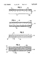
- FIG. 5 is a side sectional view of an electrode comprising two layers of porous electrically conductive material and an active layer comprising catalyst interposed between them.
- FIG. 6 is a side sectional view of a multi-layer electrode comprising four layers of porous electrically conductive material and catalyst disposed at both surfaces of each layer.
- FIG. 7 is a side sectional view of a multi-layer electrode comprising five layers of porous electrically conductive material and catalyst disposed within alternate layers.
- FIG. 8 is a side sectional view of a multi-layer electrode structured to facilitate escape of gaseous products, comprising three layers of porous electrically conductive material.
- FIG. 9 is a plot of cell voltage versus methanol utilization for a fuel cell with the conventional anode (plot A) shown in FIG. 1B and with a multi-layer anode (plot B) shown in FIG. 6.
- FIG. 1A illustrates a typical solid polymer fuel cell 10.
- Fuel cell 10 includes a membrane electrode assembly 12 consisting of an ion-exchange membrane 14 interposed between two electrodes, namely an anode 16 and a cathode 17.
- anode 16 and cathode 17 comprise a substrate of porous electrically conductive sheet material, 18 and 19, respectively.
- Each substrate has a thin layer, 20, 21, of electrocatalyst disposed on one of the major surfaces at the interface with the membrane 14.
- the membrane electrode assembly 12 is typically interposed between anode flow field or separator plate 22 and cathode flow field or separator plate 24.
- Anode separator plate 22 has at least one fuel flow channel 23 engraved, milled or molded in its surface facing anode.
- cathode separator plate 24 has at least one oxidant flow channel 25 engraved, milled or molded in its surface facing the cathode.
- FIG. 1B shows a conventional (prior art) electrode 30 of the type typically used in solid polymer fuel cells.
- Electrode 30 comprises a sheet of porous, electrically conductive material 32, typically carbon fiber paper or carbon cloth.
- the electrode 30 has oppositely facing major planar surfaces 30a, 30b.
- electrode surface 30b is adjacent to the membrane electrolyte.
- a thin layer comprising electrocatalyst particles 36 is disposed at electrode surface 30b.
- FIG. 2 shows an electrode 40 comprising porous material 42.
- the electrode 40 has oppositely facing major planar surfaces 40a, 40b.
- electrode surface 40b is adjacent to the membrane electrolyte.
- Catalyst particles 46 effective for promoting the oxidation of methanol, are distributed between the electrode surfaces 40a, 40b.
- the catalyst particles 46 may be distributed substantially uniformly throughout the volume between the electrode surfaces 40a, 40b, as shown in FIG. 2, or may be distributed nonuniformly, for example, in discrete layers or regions. Sufficient catalyst is provided so that substantially all of the methanol, which is introduced in a fluid to the electrode 40 at surface 40a is oxidized upon contacting surface 40b.
- porous material 42 is one or more layers of carbon particles mixed with a polymeric binder, and catalyst particles 46 are distributed throughout porous material 42.
- porous material 42 is glass fiber mat or expanded (porous) polytetrafluoroethylene and a matrix of carbon particles and a polymeric binder which, along with catalyst particles 46, is distributed throughout the thickness of the mat.
- porous material 42 is carbon cloth and a matrix of carbon particles and a polymeric binder which, along with catalyst particles 46, is distributed throughout the thickness of the carbon cloth.
- FIG. 3 shows an electrode 50 comprising porous electrically conductive material 52.
- the electrode 50 has oppositely facing major planar surfaces 50a, 50b.
- electrode surface 50b is adjacent the membrane electrolyte.
- Catalyst particles 56 effective for promoting the oxidation of methanol, are concentrated at electrode surface 50a.
- Sufficient catalyst is provided so that substantially all of the methanol, which is introduced in a fluid to the electrode 50 at surface 50a, is oxidized upon contacting surface 50b.
- catalyst particles 56 are applied to and impregnated into surface 50a of a porous electrically conductive material sheet material such as carbon fiber paper.
- FIG. 4 shows an electrode 60 comprising porous electrically conductive material 62.
- the electrode 60 has oppositely facing major planar surfaces 60a, 60b.
- surface 60b is adjacent to the membrane electrolyte.
- Catalyst particles 66 effective for promoting the oxidation of methanol, are concentrated at electrode surfaces 60a, 60b.
- Sufficient catalyst is provided so that substantially all of the methanol, which is introduced in a fluid to electrode 60 at surface 60a is oxidized upon contacting surface 60b.
- catalyst particles 66 are applied to and impregnated into both surfaces 60a, 60b of porous electrically conductive material 62.
- FIG. 5 shows a multi-layer electrode 70 comprising two layers of porous electrically conductive sheet material 72, 74.
- a direct methanol solid polymer fuel cell layer 74 is adjacent to the membrane electrolyte.
- An active layer 78, comprising catalyst particles 76 is interposed between layers 72, 74.
- the layers 72, 74 provide structural support for the catalyst-containing layer 78.
- Sufficient catalyst is provided so that substantially all of the methanol, introduced in a fluid at layer 72 is oxidized upon contacting layer 74.
- FIG. 6 shows a multi-layer electrode 80 comprising four layers of porous electrically conductive sheet material 82, 83, 84, 85.
- the electrode 80 has oppositely facing major planar surfaces 80a, 80b.
- surface 80b is disposed adjacent the membrane electrolyte.
- Catalyst particles 86 are disposed at both major planar surfaces of each layer.
- Sufficient catalyst is provided so that substantially all of the methanol, which is introduced in a liquid to the electrode 80 at surface 80a is oxidized upon contacting surface 80b.
- FIG. 7 shows a multi-layer electrode 90 comprising five stacked layers of porous electrically conductive sheet material 92a, 92b, 92c, 93a, 93b.
- the electrode 90 has oppositely facing major planar surfaces 90a, 90b.
- surface 90b is disposed adjacent the membrane electrolyte.
- Catalyst particles 96 are disposed in layers 92a, 92b and 92c.
- Sufficient catalyst is provided so that substantially all of the methanol, which is introduced in a fluid to the electrode 90 at surface 90a is oxidized upon contacting surface 90b.
- porous layers 92a, 92b, 92c are carbon cloth filled with a matrix of carbon particles and a polymeric binder, and catalyst particles 96 are distributed throughout the thickness of the layers 92a, 92b, 92c.
- Porous layers 93a and 93b are carbon cloth which is not filled with a matrix and catalyst particles, and are therefore more porous.
- FIG. 8 shows a multi-layer electrode 100 structured to facilitate escape of gaseous carbon dioxide product.
- Electrode 100 comprises three stacked layers of porous electrically conductive sheet material 102, 103, 104, and has oppositely facing major planar surfaces 100a, 100b.
- surface 100b is disposed adjacent the membrane electrolyte.
- Catalyst particles 106 are disposed in layers 102 and 104.
- Sufficient catalyst is provided so that substantially all of the methanol, which is introduced in a fluid to electrode 100 at surface 100a is oxidized upon contacting surface 100b.
- Layer 103 has channels 103a formed in its major planar surfaces to facilitate gas transport.
- porous material 102 and 104 is carbon cloth filled with a matrix of carbon particles and a polymeric binder, and catalyst particles 106 are distributed throughout the thickness of layers 102, 104.
- Layer 103 is carbon fiber paper with channels 103a formed in the surfaces thereof.
- Additional materials such as hydrophobic or hydrophillic polymers, and particulate fillers, may optionally be incorporated into the electrode, for example, to control gas and liquid transport in the electrode.
- protons are generated by oxidation of methanol at catalyst sites which are remote from the anode-membrane interface.
- a mechanism is provided for transporting protons from the catalyst sites to the membrane electrolyte.
- the anode further comprises proton conductive material which provides a path for transport of protons from the catalyst sites to the membrane electrolyte.
- proton conductive material may be impregnated into the at least one porous layer of the anode or may be applied in a mixture with the catalyst.
- the proton conductive material may, for example, be an ionomer such as a sulfonated fluoroionomer, for example Nafion.
- the methanol may be supplied to the anode in aqueous acidic solution, the aqueous acid thereby providing a path for transport of protons from the catalyst sites to the membrane electrolyte.
- Suitable acids include sulfuric acid and perchloric acid.
- any catalyst which is effective for the oxidation of methanol may be employed in the anode of a direct methanol fuel cell.
- the catalyst can be a metal black such as platinum, a mixture of metals, an alloy, a catalyst mixed with additives to promote electrocatalytic activity and/or inhibit catalyst poisoning, or a supported catalyst such as, for example, a noble metal on a carbon support.
- a single layer of carbon supported platinum ruthenium catalyst (Pt/Ru/C: 20/10/70%) was applied to one surface of a sheet of carbon fiber paper (14 ⁇ 14 cm, thickness 0.27 mm, Grade CFP090) to give a platinum loading of 1.80 mg/cm 2 .
- Carbon supported platinum ruthenium catalyst (Pt/Ru/C: 20/10/70%) was applied to both surfaces of three sheets of carbon fiber paper (14 ⁇ 14 cm, thickness 0.10 mm, Grade CFP030), and the sheets were stacked together to give a multi-layer anode with the same total platinum loading as in Example 1(a) above, that is 1.80 mg/cm 2 .
- Each of the above anodes was tested in a liquid feed direct methanol fuel cell employing Nafion 117 as the ion-exchange membrane (electrolyte) and a platinum black cathode (4 mg/cm 2 platinum loading).
- the fuel cell was supplied with a fixed amount of fuel which was recirculated past the anode.
- the fixed amount of fuel was 250 mL of aqueous 2M methanol solution with a 0.5M sulfuric acid concentration, and the operating conditions were as follows:
- FIG. 9 is a plot of cell voltage versus methanol utilization for a fuel cell with a conventional (plot A) and multi-layer anode (plot B) prepared as described in Example 1.
- the quantity of electricity which would be produced if all of the methanol were used (with complete oxidation) can be calculated.
- the ratio of the observed output (current ⁇ time) to the theoretical output of the fuel cell is expressed as a percentage methanol utilization in FIG. 9.
- the cell voltage drops sharply when the utilization approaches 60%. This indicates an inadequate concentration of methanol at the electrode.
- the voltage drop occurs closer to 80% utilization.
- the primary reason for fuel utilization loss (that is, the fuel cell producing less current than is theoretically possible) is methanol diffusion to the cathode. Additional contributions to the loss may be due to incomplete oxidation of methanol--less than its electrochemical equivalent of six electrons per methanol molecule. The results indicate that the multi-layer anode improves fuel utilization and reduces methanol diffusion to the cathode.
- substantially completely reacted indicates that the amount of reactant remaining unreacted is insufficient to detrimentally affect fuel cell performance.
Abstract
In an electrochemical fuel cell, a sufficient quantity of catalyst, effective for promoting the reaction of reactant supplied to an electrode, is disposed within the volume of the electrode so that a reactant introduced at a first major surface of the electrode is substantially completely reacted upon contacting the second major surface. Crossover of reactant from one electrode to the other electrode through the electrolyte in an electrochemical fuel cell is thereby reduced.
Description
The invention relates generally to electrochemical fuel cells and, more particularly, to a fuel cell with an electrode having catalyst disposed within the volume between its major surfaces. A method and apparatus for reducing reactant crossover from one electrode to the other in an electrochemical fuel cell is provided.
Electrochemical fuel cells convert fuel and oxidant to electricity and reaction product. Fluid reactants are supplied to a pair of electrodes which are in contact with and separated by an electrolyte. The electrolyte may be a solid or a liquid (supported liquid matrix). Solid polymer electrochemical fuel cells generally employ a membrane electrode assembly comprising a solid ionomer or ion-exchange membrane disposed between two planar electrodes. The electrodes typically comprise an electrode substrate and an electrocatalyst layer disposed upon one major surface of the electrode substrate. The electrode substrate typically comprises a sheet of porous, electrically conductive material, such as carbon fiber paper or carbon cloth. The layer of electrocatalyst is typically in the form of finely comminuted metal, typically platinum, and is disposed on the surface of the electrode substrate at the interface with the membrane electrolyte in order to induce the desired electrochemical reaction. In a single cell, the electrodes are electrically coupled to provide a path for conducting electrons between the electrodes through an external load.
At the anode, the fuel moves through the porous anode substrate and is oxidized at the anode electrocatalyst layer. At the cathode, the oxidant moves through the porous cathode substrate and is reduced at the cathode electrocatalyst layer.
Electrochemical fuel cells most commonly employ gaseous fuels and oxidants, for example, those operating on molecular hydrogen as the fuel and oxygen in air or a carrier gas (or substantially pure oxygen) as the oxidant. The anode and cathode reactions in hydrogen/oxygen fuel cells are shown in the following equations:
Anode reaction: H2 →2H+ +2e
Cathode reaction: 1/202 +2H+ +2e- →H2 O
The catalyzed reaction at the anode produces hydrogen cations (protons) from the fuel supply. The ion-exchange membrane facilitates the migration of protons from the anode to the cathode. In addition to conducting protons, the membrane isolates the hydrogen-containing gaseous fuel stream from the oxygen-containing gaseous oxidant stream. At the cathode electrocatalyst layer, oxygen reacts with the protons that have crossed the membrane to form water as the reaction product.
In liquid feed electrochemical fuel cells, one or more of the reactants is introduced to the electrocatalyst in the liquid form. Examples of electrochemical fuel cells which can be operated with a liquid fuel feed are those employing a lower alcohol, most commonly methanol, as the fuel supplied to the anode (so-called "direct methanol" fuel cells) and oxygen to the cathode. In fuel cells of this type the reaction at the anode produces protons, as in the hydrogen/oxygen fuel cell described above, however the protons (along with carbon dioxide) arise from the oxidation of methanol. An electrocatalyst promotes the methanol oxidation at the anode. The methanol may alternatively be supplied to the anode as vapor, but it is generally advantageous to supply the methanol to the anode as a liquid, preferably as an aqueous solution. In some situations, an acidic aqueous methanol solution is the preferred feed to the anode. The anode and cathode reactions in a direct methanol fuel cell are shown in the following equations:
Anode reaction: CH3 OH+H2 O →6H+ +CO2 +6e-
Cathode reaction: 3/2O2 +6H+ +6e- →3H2 O
Overall reaction: CH3 OH+3/2O2 →CO2 +2H2 O
The protons formed at the anode electrocatalyst migrate through the ion-exchange membrane from the anode to the cathode, and at the cathode electrocatalyst layer, the oxidant reacts with the protons to form water.
Other non-alcohol fuels may be used in liquid feed fuel cells, for example formic acid. The oxidant may also be supplied as a liquid, for example, as an organic fluid with a high oxygen concentration (see U.S. Pat. No. 5,185,218), or as a hydrogen peroxide solution.
In electrochemical fuel cells employing liquid or solid electrolytes and gaseous or liquid reactant streams, crossover of a reactant from one electrode to the other is generally undesirable. Reactant crossover may occur if the electrolyte is permeable to the reactant, that is, some of a reactant introduced at a first electrode of the fuel cell may pass through the electrolyte to the second electrode, instead of reacting at the first electrode. Reactant crossover typically causes a decrease in both reactant utilization efficiency and fuel cell performance. Fuel cell performance is defined as the voltage output from the cell at a given current density or vice versa; the higher the voltage at a given current density or the higher the current density at a given voltage, the better the performance.
In solid polymer electrochemical fuel cells the ion-exchange membrane may be permeable to one or more of the reactants. For example, ion-exchange membranes typically employed in solid polymer electrochemical fuel cells are permeable to methanol, thus methanol which contacts the membrane prior to participating in the oxidation reaction can cross over to the cathode side. Diffusion of methanol fuel from the anode to the cathode leads to a reduction in fuel utilization efficiency and to performance losses (see, for example, S. Surampudi et al., Journal of Power Sources, vol.47, 377-385 (1994) and C. Pu et al., Journal of the Electrochemical Society, vol. 142, L119-120 (1995)).
Fuel utilization efficiency losses arise from methanol diffusion away from the anode because some of the methanol which would otherwise participate in the oxidation reaction at the anode and supply electrons to do work through the external circuit is lost. Methanol arriving at the cathode may be lost through vaporization into the oxidant stream, or may be oxidized at the cathode electrocatalyst, consuming oxidant, as follows:
CH3 OH+3/2O2 →CO2 +2H2 O
Methanol diffusion to the cathode may lead to a decrease in fuel cell performance. The oxidation of methanol at the cathode reduces the concentration of oxygen at the electrocatalyst and may affect access of the oxidant to the electrocatalyst (mass transport issues). Further, depending upon the nature of the cathode electrocatalyst and the oxidant supply, the electrocatalyst may be poisoned by methanol oxidation products, or sintered by the methanol oxidation reaction.
The electrode structures presently used in direct methanol solid polymer fuel cells were originally developed for hydrogen/oxygen fuel cells. The anode electrocatalyst which promotes the oxidation of methanol to produce protons is typically provided as a thin layer adjacent to the ion-exchange membrane (see U.S. Pat. Nos. 5,132,193 and 5,409,785 and European Patent Publication No. 0090358). The anode electrocatalyst layer is typically applied as a coating to one major surface of a sheet of porous, electrically conductive sheet material or to one surface of the ion-exchange membrane. This provides a limited reaction zone in which the methanol can be oxidized before contacting the membrane electrolyte. Thus, with this type of electrode, the methanol concentration at the anode-electrolyte interface will typically be high.
Reactant crossover may be substantially eliminated if a reactant introduced to a first major surface of a fuel cell electrode is substantially completely reacted on contacting the second major surface of the electrode. In this case essentially no unreacted reactant would be available to pass from the second surface through the electrolyte to the other electrode. As described herein, this may be accomplished by ensuring that the reactant contacts sufficient catalyst so that it is substantially completely reacted before it contacts the second surface of the electrode.
It is therefore an object of the invention to provide an electrochemical fuel cell in which crossover of a reactant from one electrode to the other is reduced.
It is a further object of the invention to provide a solid polymer electrochemical fuel cell in which a reactant is substantially completely reacted before it contacts the membrane electrolyte.
It is a still further object of the invention to provide a direct methanol solid polymer fuel cell in which methanol crossover from the anode to the cathode is reduced.
Another object of the invention is to provide a method for reducing reactant crossover in an electrochemical fuel cell.
The above and other objects are achieved by an electrochemical fuel cell in which an electrode has catalyst disposed within the volume thereof. The electrochemical fuel cell comprises:
(a) a first electrode, the first electrode having first and second oppositely facing major surfaces, the first electrode comprising at least one layer of porous material and a sufficient quantity of catalyst disposed within the volume of the electrode between the major surfaces so that a reactant in a fluid introduced to the first major surface of the first electrode is substantially completely reacted upon contacting the second major surface of the first electrode;
(b) a second electrode;
(c) an electrolyte interposed between the second major surface of the first electrode and the second electrode.
In a preferred aspect of an electrochemical fuel cell the first and second oppositely facing major surfaces of the first electrode are planar.
In one embodiment the catalyst is distributed substantially uniformly within the volume between the first and second oppositely facing major surfaces of the first electrode. In an alternative embodiment the catalyst is distributed nonuniformly, such as, for example, in discrete layers or regions. The at least one layer of porous material may optionally comprise a plurality of stacked layers, and may optionally further comprise carbon particles. Suitable carbon particles include acetylene blacks, furnace blacks and graphite particles.
The electrolyte may be a liquid or a solid. With a liquid electrolyte a porous, electrically non-conductive separator is typically employed between the two electrodes. In a preferred embodiment the electrochemical fuel cell is a solid polymer fuel cell and the electrolyte comprises an ion-exchange membrane. The at least one layer of porous material is preferably electrically conductive and in a further embodiment comprises a proton conductor. Preferred porous materials comprise electrically conductive sheet material such as carbon fiber paper or carbon cloth. In an alternative aspect the at least one layer of porous material comprises carbon particles and a polymeric binder.
The fluid in which the reactant is introduced may be a liquid or a gas.
In a preferred embodiment of a liquid feed electrochemical fuel cell, the first electrode is an anode and the reactant comprises an alcohol, preferably methanol. In this case the catalyst promotes the oxidation of methanol. The fluid in which the methanol is introduced preferably comprises water and may optionally further comprise acid. In a preferred embodiment of a liquid feed direct methanol fuel cell the at least one layer of porous material comprises a plurality of carbon fiber paper layers each of the layers having two oppositely facing major surfaces, wherein catalyst is disposed on at least one major surface of each of the layers.
In any of the above embodiments of a solid polymer electrochemical fuel cell, catalyst may also be applied to the surface of the ion-exchange membrane.
The electrode has first and second oppositely facing major surfaces and comprises:
(a) at least one layer of porous material;
(b) a sufficient quantity of catalyst disposed within the volume of the electrode between the major surfaces so that a reactant in a fluid introduced to the first major surface of the electrode is substantially completely reacted upon contacting the second major surface of the electrode.
In a preferred aspect of an electrode the first and second oppositely facing major surfaces of the electrode are planar.
In the electrode, the porous material acts as a carrier for the catalyst, and is preferably liquid and gas permeable, to allow gas or liquid feed reactant to penetrate it and to allow gaseous products to escape. The porous material may be electrically non-conductive or preferably electrically conductive. The electrode, as a whole, is electrically conductive, however non-conductive porous material incorporating sufficient catalyst and/or other electrically conductive material to render the electrode electrically conductive may be used. The porous material may, for example, be one or more layers of electrically conductive particles, such as carbon particles, and a polymeric binder. The preferred porous material includes a sheet material which is self-supporting and has structural integrity, thus providing structural support for the adjacent ion-exchange membrane in solid polymer fuel cells. Suitable non-conductive sheet materials include expanded polytetrafluoroethylene and glass fiber matting, which preferably have electrically conductive particles, such as, for example, carbon particles associated therewith. Suitable electrically conductive sheet materials include carbon aerogel, carbon foam, carbon sponge, expanded metals and reticulated metals. Preferred sheet materials include carbon fiber paper and carbon cloth. The electrode may optionally incorporate structures to facilitate movement of gaseous products away from the electrode, for example, channels, grooves and layers or regions of different porosities.
In general, in electrochemical fuel cells, higher catalyst loadings lead to improved performance. The electrode structures described herein facilitate use of higher catalyst loadings.
In a method of substantially completely reacting a reactant in a fluid within a first electrode of an electrochemical fuel cell, the first electrode having first and second oppositely facing major surfaces, the reactant introduced at the first major surface, the first electrode comprising at least one layer of porous material and a catalyst, and the fuel cell further comprising a second electrode and an electrolyte interposed between the second major surface of the first electrode and the second electrode, the method comprises:
disposing a sufficient quantity of the catalyst within the volume of the first electrode between the major surfaces thereof such that the reactant is substantially completely reacted upon contacting the second major surface.
FIG. 1A is an exploded side view of a typical solid polymer electrochemical fuel cell showing a conventional membrane electrode assembly interposed between two separator plates, the separator plates having reactant flow channels formed in the surfaces for directing the reactants to the electrodes.
FIG. 1B is a side sectional view of a conventional (prior art) solid polymer electrochemical fuel cell electrode having the catalyst disposed in a single, discrete layer at the interface with the membrane electrolyte.
FIG. 2 is a side sectional view of an electrode having catalyst substantially uniformly distributed throughout the volume of the electrode.
FIG. 3 is a side sectional view of an electrode having a catalyst layer impregnated into, and disposed in the volume underlying, the surface of the electrode facing away from the membrane electrolyte.
FIG. 4 is a side sectional view of an electrode having a catalyst layer impregnated into both surfaces of the electrode.
FIG. 5 is a side sectional view of an electrode comprising two layers of porous electrically conductive material and an active layer comprising catalyst interposed between them.
FIG. 6 is a side sectional view of a multi-layer electrode comprising four layers of porous electrically conductive material and catalyst disposed at both surfaces of each layer.
FIG. 7 is a side sectional view of a multi-layer electrode comprising five layers of porous electrically conductive material and catalyst disposed within alternate layers.
FIG. 8 is a side sectional view of a multi-layer electrode structured to facilitate escape of gaseous products, comprising three layers of porous electrically conductive material.
FIG. 9 is a plot of cell voltage versus methanol utilization for a fuel cell with the conventional anode (plot A) shown in FIG. 1B and with a multi-layer anode (plot B) shown in FIG. 6.
FIG. 1A illustrates a typical solid polymer fuel cell 10. Fuel cell 10 includes a membrane electrode assembly 12 consisting of an ion-exchange membrane 14 interposed between two electrodes, namely an anode 16 and a cathode 17. In conventional solid polymer fuel cells, anode 16 and cathode 17 comprise a substrate of porous electrically conductive sheet material, 18 and 19, respectively. Each substrate has a thin layer, 20, 21, of electrocatalyst disposed on one of the major surfaces at the interface with the membrane 14. The membrane electrode assembly 12 is typically interposed between anode flow field or separator plate 22 and cathode flow field or separator plate 24. Anode separator plate 22 has at least one fuel flow channel 23 engraved, milled or molded in its surface facing anode. Similarly, cathode separator plate 24 has at least one oxidant flow channel 25 engraved, milled or molded in its surface facing the cathode. When assembled against the co-operating surfaces of electrodes 16 and 17, channels 23 and 25 form the reactant flow field passages for the fuel and oxidant respectively.
FIG. 1B shows a conventional (prior art) electrode 30 of the type typically used in solid polymer fuel cells. Electrode 30 comprises a sheet of porous, electrically conductive material 32, typically carbon fiber paper or carbon cloth. The electrode 30 has oppositely facing major planar surfaces 30a, 30b. In a conventional solid polymer fuel cell, electrode surface 30b is adjacent to the membrane electrolyte. A thin layer comprising electrocatalyst particles 36 is disposed at electrode surface 30b.
FIG. 2 shows an electrode 40 comprising porous material 42. The electrode 40 has oppositely facing major planar surfaces 40a, 40b. In a direct methanol fuel cell, electrode surface 40b is adjacent to the membrane electrolyte. Catalyst particles 46, effective for promoting the oxidation of methanol, are distributed between the electrode surfaces 40a, 40b. The catalyst particles 46 may be distributed substantially uniformly throughout the volume between the electrode surfaces 40a, 40b, as shown in FIG. 2, or may be distributed nonuniformly, for example, in discrete layers or regions. Sufficient catalyst is provided so that substantially all of the methanol, which is introduced in a fluid to the electrode 40 at surface 40a is oxidized upon contacting surface 40b. The thickness of the electrode 40 and the quantity of catalyst required will depend for example on the rate of methanol supply to the electrode 40, and the rate of fluid transport through the electrode 40. In one example of an electrode 40, porous material 42 is one or more layers of carbon particles mixed with a polymeric binder, and catalyst particles 46 are distributed throughout porous material 42. In another example of an electrode 40, porous material 42 is glass fiber mat or expanded (porous) polytetrafluoroethylene and a matrix of carbon particles and a polymeric binder which, along with catalyst particles 46, is distributed throughout the thickness of the mat. In preferred example of an electrode 40, porous material 42 is carbon cloth and a matrix of carbon particles and a polymeric binder which, along with catalyst particles 46, is distributed throughout the thickness of the carbon cloth.
FIG. 3 shows an electrode 50 comprising porous electrically conductive material 52. The electrode 50 has oppositely facing major planar surfaces 50a, 50b. In a direct methanol solid polymer fuel cell, electrode surface 50b is adjacent the membrane electrolyte. Catalyst particles 56, effective for promoting the oxidation of methanol, are concentrated at electrode surface 50a. Sufficient catalyst is provided so that substantially all of the methanol, which is introduced in a fluid to the electrode 50 at surface 50a, is oxidized upon contacting surface 50b. In an example of an electrode 50, catalyst particles 56 are applied to and impregnated into surface 50a of a porous electrically conductive material sheet material such as carbon fiber paper.
FIG. 4 shows an electrode 60 comprising porous electrically conductive material 62. The electrode 60 has oppositely facing major planar surfaces 60a, 60b. In a direct methanol solid polymer fuel cell electrode, surface 60b is adjacent to the membrane electrolyte. Catalyst particles 66, effective for promoting the oxidation of methanol, are concentrated at electrode surfaces 60a, 60b. Sufficient catalyst is provided so that substantially all of the methanol, which is introduced in a fluid to electrode 60 at surface 60a is oxidized upon contacting surface 60b. In an example of an electrode 60, catalyst particles 66 are applied to and impregnated into both surfaces 60a, 60b of porous electrically conductive material 62.
FIG. 5 shows a multi-layer electrode 70 comprising two layers of porous electrically conductive sheet material 72, 74. In a direct methanol solid polymer fuel cell layer 74 is adjacent to the membrane electrolyte. An active layer 78, comprising catalyst particles 76 is interposed between layers 72, 74. The layers 72, 74 provide structural support for the catalyst-containing layer 78. Sufficient catalyst is provided so that substantially all of the methanol, introduced in a fluid at layer 72 is oxidized upon contacting layer 74.
FIG. 6 shows a multi-layer electrode 80 comprising four layers of porous electrically conductive sheet material 82, 83, 84, 85. The electrode 80 has oppositely facing major planar surfaces 80a, 80b. In a direct methanol solid polymer fuel cell electrode, surface 80b is disposed adjacent the membrane electrolyte. Catalyst particles 86 are disposed at both major planar surfaces of each layer. Sufficient catalyst is provided so that substantially all of the methanol, which is introduced in a liquid to the electrode 80 at surface 80a is oxidized upon contacting surface 80b.
FIG. 7 shows a multi-layer electrode 90 comprising five stacked layers of porous electrically conductive sheet material 92a, 92b, 92c, 93a, 93b. The electrode 90 has oppositely facing major planar surfaces 90a, 90b. In a direct methanol solid polymer fuel cell electrode, surface 90b is disposed adjacent the membrane electrolyte. Catalyst particles 96 are disposed in layers 92a, 92b and 92c. Sufficient catalyst is provided so that substantially all of the methanol, which is introduced in a fluid to the electrode 90 at surface 90a is oxidized upon contacting surface 90b. In an example of an electrode 90 structured to facilitate escape of gaseous carbon dioxide product, porous layers 92a, 92b, 92c are carbon cloth filled with a matrix of carbon particles and a polymeric binder, and catalyst particles 96 are distributed throughout the thickness of the layers 92a, 92b, 92c. Porous layers 93a and 93b are carbon cloth which is not filled with a matrix and catalyst particles, and are therefore more porous.
FIG. 8 shows a multi-layer electrode 100 structured to facilitate escape of gaseous carbon dioxide product. Electrode 100 comprises three stacked layers of porous electrically conductive sheet material 102, 103, 104, and has oppositely facing major planar surfaces 100a, 100b. In a direct methanol solid polymer fuel cell electrode, surface 100b is disposed adjacent the membrane electrolyte. Catalyst particles 106 are disposed in layers 102 and 104. Sufficient catalyst is provided so that substantially all of the methanol, which is introduced in a fluid to electrode 100 at surface 100a is oxidized upon contacting surface 100b. Layer 103 has channels 103a formed in its major planar surfaces to facilitate gas transport. In an example of an electrode 100, porous material 102 and 104 is carbon cloth filled with a matrix of carbon particles and a polymeric binder, and catalyst particles 106 are distributed throughout the thickness of layers 102, 104. Layer 103 is carbon fiber paper with channels 103a formed in the surfaces thereof.
Additional materials, such as hydrophobic or hydrophillic polymers, and particulate fillers, may optionally be incorporated into the electrode, for example, to control gas and liquid transport in the electrode.
In the direct methanol solid polymer fuel cells described herein, protons are generated by oxidation of methanol at catalyst sites which are remote from the anode-membrane interface. A mechanism is provided for transporting protons from the catalyst sites to the membrane electrolyte. In preferred embodiments, the anode further comprises proton conductive material which provides a path for transport of protons from the catalyst sites to the membrane electrolyte. For example, proton conductive material may be impregnated into the at least one porous layer of the anode or may be applied in a mixture with the catalyst. The proton conductive material may, for example, be an ionomer such as a sulfonated fluoroionomer, for example Nafion. Alternatively, or in addition, the methanol may be supplied to the anode in aqueous acidic solution, the aqueous acid thereby providing a path for transport of protons from the catalyst sites to the membrane electrolyte. Suitable acids include sulfuric acid and perchloric acid.
Any catalyst which is effective for the oxidation of methanol may be employed in the anode of a direct methanol fuel cell. For example, the catalyst can be a metal black such as platinum, a mixture of metals, an alloy, a catalyst mixed with additives to promote electrocatalytic activity and/or inhibit catalyst poisoning, or a supported catalyst such as, for example, a noble metal on a carbon support.
(a) Preparation of a Conventional Anode
A single layer of carbon supported platinum ruthenium catalyst (Pt/Ru/C: 20/10/70%) was applied to one surface of a sheet of carbon fiber paper (14×14 cm, thickness 0.27 mm, Grade CFP090) to give a platinum loading of 1.80 mg/cm2.
(b) Preparation of a Multi-layer Anode
Carbon supported platinum ruthenium catalyst (Pt/Ru/C: 20/10/70%) was applied to both surfaces of three sheets of carbon fiber paper (14×14 cm, thickness 0.10 mm, Grade CFP030), and the sheets were stacked together to give a multi-layer anode with the same total platinum loading as in Example 1(a) above, that is 1.80 mg/cm2.
Each of the above anodes was tested in a liquid feed direct methanol fuel cell employing Nafion 117 as the ion-exchange membrane (electrolyte) and a platinum black cathode (4 mg/cm2 platinum loading). In both cases the fuel cell was supplied with a fixed amount of fuel which was recirculated past the anode. The fixed amount of fuel was 250 mL of aqueous 2M methanol solution with a 0.5M sulfuric acid concentration, and the operating conditions were as follows:
current density--constant at 200 mA/cm2
temperature=115° C.
air inlet pressure=35 psig
air stoichiometry=3
FIG. 9 is a plot of cell voltage versus methanol utilization for a fuel cell with a conventional (plot A) and multi-layer anode (plot B) prepared as described in Example 1. The quantity of electricity which would be produced if all of the methanol were used (with complete oxidation) can be calculated. The ratio of the observed output (current×time) to the theoretical output of the fuel cell is expressed as a percentage methanol utilization in FIG. 9. For the conventional anode, the cell voltage drops sharply when the utilization approaches 60%. This indicates an inadequate concentration of methanol at the electrode. For the multi-layer anode the voltage drop occurs closer to 80% utilization. The primary reason for fuel utilization loss (that is, the fuel cell producing less current than is theoretically possible) is methanol diffusion to the cathode. Additional contributions to the loss may be due to incomplete oxidation of methanol--less than its electrochemical equivalent of six electrons per methanol molecule. The results indicate that the multi-layer anode improves fuel utilization and reduces methanol diffusion to the cathode.
As used herein the term "substantially completely reacted" indicates that the amount of reactant remaining unreacted is insufficient to detrimentally affect fuel cell performance.
While particular elements, embodiments and applications of the present invention have been shown and described, it will be understood, of course, that the invention is not limited thereto since modifications may be made by those skilled in the art, particularly in light of the foregoing teachings. It is therefore contemplated by the appended claims to cover such modifications as incorporate those features which come within the spirit and scope of the invention.
Claims (24)
1. An electrochemical fuel cell comprising:
(a) a first electrode, said first electrode having first and second oppositely facing major surfaces, said first electrode comprising at least one layer of porous material and a sufficient quantity of catalyst disposed within the volume of said electrode between said major surfaces so that a reactant in a fluid introduced to said first major surface of said first electrode is substantially completely reacted upon contacting said second major surface of said first electrode;
(b) a second electrode;
(c) an electrolyte interposed between said second major surface of said first electrode and said second electrode;
wherein said at least one layer of porous material comprises a plurality of stacked layers.
2. An electrochemical fuel cell comprising:
(a) a first electrode, said first electrode having first and second oppositely facing major surfaces, said first electrode comprising (1) at least one layer of porous electrically conductive material comprising a proton conductor and (2) a sufficient quantity of catalyst disposed within the volume of said electrode between said major surfaces so that a reactant in a fluid introduced to said first major surface of said first electrode is substantially completely reacted upon contacting said second major surface of said first electrode;
(b) a second electrode;
(c) an electrolyte interposed between said second major surface of said first electrode and said second electrode, said electrolyte comprising an ion-exchange membrane;
wherein said at least one layer of porous electrically conductive material comprises carbon fiber paper.
3. An electrochemical fuel cell comprising:
(a) a first electrode, said first electrode having first and second oppositely facing major surfaces, said first electrode comprising (1) at least one layer of porous electrically conductive material comprising a proton conductor and (2) a sufficient quantity of catalyst disposed within the volume of said electrode between said major surfaces so that a reactant in a fluid introduced to said first major surface of said first electrode is substantially completely reacted upon contacting said second major surface of said first electrode;
(b) a second electrode;
(c) an electrolyte interposed between said second major surface of said first electrode and said second electrode, said electrolyte comprising an ion-exchange membrane;
wherein said at least one layer of porous electrically conductive material comprises carbon cloth.
4. An electrochemical fuel cell comprising:
(a) a first electrode, said first electrode having first and second oppositely facing major surfaces, said first electrode comprising (1) at least one layer of porous electrically conductive material comprising a proton conductor and (2) a sufficient quantity of catalyst disposed within the volume of said electrode between said major surfaces so that a reactant in a liquid introduced to said first major surface of said first electrode is substantially completely reacted upon contacting said second major surface of said first electrode;
(b) a second electrode;
(c) an electrolyte interposed between said second major surface of said first electrode and said second electrode, said electrolyte comprising an ion-exchange
wherein said first electrode is an anode and said reactant comprises an alcohol.
5. The electrochemical fuel cell of claim 4 wherein said alcohol is methanol and said quantity of catalyst promotes the oxidation of methanol.
6. The electrochemical fuel cell of claim 5 wherein said liquid comprises water.
7. The electrochemical fuel cell of claim 6 wherein said liquid further comprises acid.
8. The electrochemical fuel cell of claim 7 wherein said at least one layer of porous electrically conductive material comprises a plurality of carbon fiber paper layers each of said layers having two oppositely facing major surfaces, and wherein said quantity of catalyst is disposed on at least one major surface of each of said layers.
9. An electrode for an electrochemical fuel cell, said electrode having first and second oppositely facing major surfaces, said electrode comprising:
(a) at least one layer of porous material;
(b) a sufficient quantity of catalyst disposed within the volume of said electrode between said major surfaces so that a reactant in a fluid introduced to said first major surface of said first electrode is substantially completely reacted upon contacting said second major surface of said electrode;
wherein said at least one layer of porous material comprises a plurality of stacked layers.
10. An electrode for an electrochemical fuel cell comprising an electrolyte comprising an ion-exchange membrane, said electrode having first and second oppositely facing major surfaces, said electrode comprising:
(a) at least one layer of porous electrically conductive material comprising a proton conductor;
(b) a sufficient quantity of catalyst disposed within the volume of said electrode between said major surfaces so that a reactant in a fluid introduced to said first major surface of said electrode is substantially completely reacted upon contacting said second major surface of said electrode;
wherein said at least one layer of porous electrically conductive material comprises carbon fiber paper.
11. An electrode for an electrochemical fuel cell comprising an electrolyte comprising an ion-exchange membrane, said electrode having first and second oppositely facing major surfaces, said electrode comprising:
(a) at least one layer of porous electrically conductive material comprising a proton conductor;
(b) a sufficient quantity of catalyst disposed within the volume of said electrode between said major surfaces so that a reactant in a fluid introduced to said first major surface of said electrode is substantially completely reacted upon contacting said second major surface of said electrode;
wherein said at least one layer of porous electrically conductive material comprises carbon cloth.
12. An electrode for an electrochemical fuel cell comprising an electrolyte comprising an ion-exchange membrane, said electrode having first and second oppositely facing major surfaces, said electrode comprising:
(a) at least one layer of porous electrically conductive material comprising a proton conductor;
(b) a sufficient quantity of catalyst disposed within the volume of said electrode between said major surfaces so that a reactant in a liquid introduced to said first major surface of said electrode is substantially completely reacted upon contacting said second major surface of said electrode;
wherein said electrode is an anode and said reactant comprises an alcohol.
13. The electrode of claim 12 wherein said alcohol is methanol and said quantity of catalyst promotes the oxidation of methanol.
14. The electrode of claim 13 wherein said liquid comprises water.
15. The electrode of claim 14 wherein said liquid further comprises acid.
16. The electrode of claim 15 wherein said at least one layer of porous electrically conductive material comprises a plurality of carbon fiber paper layers each of said layers having two oppositely facing major surfaces, and wherein said quantity of catalyst is disposed on at least one major surface of each of said layers.
17. A method of reducing reactant crossover from a first electrode of an electrochemical fuel cell to a second electrode thereof, said first electrode having first and second oppositely facing major surfaces, said reactant introduced in a fluid at said first major surface, said first electrode comprising at least one layer of porous material and a catalyst, said fuel cell further comprising an electrolyte interposed between said second major surface of said first electrode and said second electrode, the method comprising:
disposing a sufficient quantity of said catalyst within the volume of said first electrode between said major surfaces such that said reactant is substantially completely reacted upon contacting said second major surface;
wherein said at least one layer of porous material comprises a plurality of stacked layers.
18. A method of reducing reactant crossover from a first electrode of an electrochemical fuel cell to a second electrode thereof, said first electrode having first and second oppositely facing major surfaces, said reactant introduced in a fluid at said first major surface, said first electrode comprising (a) at least one layer of porous electrically conductive material comprising a proton conductor and (b) a catalyst, said fuel cell further comprising an electrolyte interposed between said second major surface of said first electrode and said second electrode, said electrolyte comprising an ion-exchange membrane, the method comprising:
disposing a sufficient quantity of said catalyst within the volume of said first electrode between said major surfaces such that said reactant is substantially completely reacted upon contacting said second major surface;
wherein said at least one layer of porous electrically conductive material comprises carbon fiber paper.
19. A method of reducing reactant crossover from a first electrode of an electrochemical fuel cell to a second electrode thereof, said first electrode having first and second oppositely facing major surfaces, said reactant introduced in a fluid at said first major surface, said first electrode comprising (a) at least one layer of porous electrically conductive material comprising a proton conductor and (b) a catalyst, said fuel cell further comprising an electrolyte interposed between said second major surface of said first electrode and said second electrode, said electrolyte comprising an ion-exchange membrane, the method comprising:
disposing a sufficient quantity of said catalyst within the volume of said first electrode between said major surfaces such that said reactant is substantially completely reacted upon contacting said second major surface;
wherein said at least one layer of porous electrically conductive material comprises carbon cloth.
20. A method of reducing reactant crossover from a first electrode of an electrochemical fuel cell to a second electrode thereof, said first electrode having first and second oppositely facing major surfaces, said reactant introduced in a liquid at said first major surface, said first electrode comprising (a) at least one layer of porous electrically conductive material comprising a proton conductor and (b) a catalyst, said fuel cell further comprising an electrolyte interposed between said second major surface of said first electrode and said second electrode, said electrolyte comprising an ion-exchange membrane, the method comprising:
disposing a sufficient quantity of said catalyst within the volume of said first electrode between said major surfaces such that said reactant is substantially completely reacted upon contacting said second major surface;
wherein said electrode is an anode and said reactant comprises an alcohol.
21. The method of claim 20 wherein said alcohol is methanol and said quantity of catalyst promotes the oxidation of methanol.
22. The method of claim 20 wherein said liquid comprises water.
23. The method of claim 22 wherein said liquid further comprises acid.
24. The method of claim 23 wherein said at least one layer of porous electrically conductive material comprises a plurality of carbon fiber paper layers each of said layers having two oppositely facing major surfaces, and wherein said quantity of catalyst is disposed on at least one major surface of each of said layers.
Priority Applications (12)
| Application Number | Priority Date | Filing Date | Title |
|---|---|---|---|
| US08/574,262 US5672439A (en) | 1995-12-18 | 1995-12-18 | Method and apparatus for reducing reactant crossover in an electrochemical fuel cell |
| CA002240661A CA2240661C (en) | 1995-12-18 | 1996-11-25 | Method and apparatus for reducing reactant crossover in an electrochemical fuel cell |
| JP09522370A JP2000502205A (en) | 1995-12-18 | 1996-11-25 | Method and apparatus for reducing reactant crossover in an electrochemical fuel cell |
| PCT/CA1996/000773 WO1997023010A1 (en) | 1995-12-18 | 1996-11-25 | Method and apparatus for reducing reactant crossover in an electrochemical fuel cell |
| EP96938875A EP0868758B1 (en) | 1995-12-18 | 1996-11-25 | Apparatus for reducing reactant crossover in an electrochemical fuel cell |
| AU76151/96A AU697097B2 (en) | 1995-12-18 | 1996-11-25 | Method and apparatus for reducing reactant crossover in an electrochemical fuel cell |
| DE69622747T DE69622747T2 (en) | 1995-12-18 | 1996-11-25 | DEVICE FOR REDUCING REACTANT TRANSFER IN AN ELECTROCHEMICAL FUEL CELL |
| US08/768,650 US5863673A (en) | 1995-12-18 | 1996-12-18 | Porous electrode substrate for an electrochemical fuel cell |
| US08/939,673 US5874182A (en) | 1995-12-18 | 1997-09-29 | Method and apparatus for reducing reactant crossover in a liquid feed electrochemical fuel cell |
| US09/217,177 US6060190A (en) | 1995-12-18 | 1998-12-21 | Electrochemical fuel cell membrane electrode assembly with porous electrode substrate |
| US09/255,428 US6613464B1 (en) | 1995-12-18 | 1999-02-22 | Method and apparatus for reducing reactant crossover in a liquid feed electrochemical fuel cell |
| US10/633,413 US20040023091A1 (en) | 1995-12-18 | 2003-08-01 | Method and apparatus for reducing reactant crossover in a liquid feed electrochemical fuel cell |
Applications Claiming Priority (1)
| Application Number | Priority Date | Filing Date | Title |
|---|---|---|---|
| US08/574,262 US5672439A (en) | 1995-12-18 | 1995-12-18 | Method and apparatus for reducing reactant crossover in an electrochemical fuel cell |
Related Child Applications (3)
| Application Number | Title | Priority Date | Filing Date |
|---|---|---|---|
| US08/768,650 Continuation-In-Part US5863673A (en) | 1995-12-18 | 1996-12-18 | Porous electrode substrate for an electrochemical fuel cell |
| US08/939,673 Continuation US5874182A (en) | 1995-12-18 | 1997-09-29 | Method and apparatus for reducing reactant crossover in a liquid feed electrochemical fuel cell |
| US09/217,177 Continuation-In-Part US6060190A (en) | 1995-12-18 | 1998-12-21 | Electrochemical fuel cell membrane electrode assembly with porous electrode substrate |
Publications (1)
| Publication Number | Publication Date |
|---|---|
| US5672439A true US5672439A (en) | 1997-09-30 |
Family
ID=24295360
Family Applications (4)
| Application Number | Title | Priority Date | Filing Date |
|---|---|---|---|
| US08/574,262 Expired - Fee Related US5672439A (en) | 1995-12-18 | 1995-12-18 | Method and apparatus for reducing reactant crossover in an electrochemical fuel cell |
| US08/939,673 Expired - Fee Related US5874182A (en) | 1995-12-18 | 1997-09-29 | Method and apparatus for reducing reactant crossover in a liquid feed electrochemical fuel cell |
| US09/255,428 Expired - Fee Related US6613464B1 (en) | 1995-12-18 | 1999-02-22 | Method and apparatus for reducing reactant crossover in a liquid feed electrochemical fuel cell |
| US10/633,413 Abandoned US20040023091A1 (en) | 1995-12-18 | 2003-08-01 | Method and apparatus for reducing reactant crossover in a liquid feed electrochemical fuel cell |
Family Applications After (3)
| Application Number | Title | Priority Date | Filing Date |
|---|---|---|---|
| US08/939,673 Expired - Fee Related US5874182A (en) | 1995-12-18 | 1997-09-29 | Method and apparatus for reducing reactant crossover in a liquid feed electrochemical fuel cell |
| US09/255,428 Expired - Fee Related US6613464B1 (en) | 1995-12-18 | 1999-02-22 | Method and apparatus for reducing reactant crossover in a liquid feed electrochemical fuel cell |
| US10/633,413 Abandoned US20040023091A1 (en) | 1995-12-18 | 2003-08-01 | Method and apparatus for reducing reactant crossover in a liquid feed electrochemical fuel cell |
Country Status (7)
| Country | Link |
|---|---|
| US (4) | US5672439A (en) |
| EP (1) | EP0868758B1 (en) |
| JP (1) | JP2000502205A (en) |
| AU (1) | AU697097B2 (en) |
| CA (1) | CA2240661C (en) |
| DE (1) | DE69622747T2 (en) |
| WO (1) | WO1997023010A1 (en) |
Cited By (61)
| Publication number | Priority date | Publication date | Assignee | Title |
|---|---|---|---|---|
| US5863673A (en) * | 1995-12-18 | 1999-01-26 | Ballard Power Systems Inc. | Porous electrode substrate for an electrochemical fuel cell |
| US5874182A (en) * | 1995-12-18 | 1999-02-23 | Ballard Power Systems Inc. | Method and apparatus for reducing reactant crossover in a liquid feed electrochemical fuel cell |
| US5958616A (en) * | 1998-02-06 | 1999-09-28 | Lynntech, Inc. | Membrane and electrode structure for methanol fuel cell |
| US6010798A (en) * | 1995-04-07 | 2000-01-04 | Siemens Aktiengesellschaft | PEM fuel cell |
| GB2339058A (en) * | 1998-07-01 | 2000-01-12 | British Gas Plc | Electrochemical fuel cellassembly having an undulate membrane electrode assembly |
| WO2000036679A1 (en) * | 1998-12-18 | 2000-06-22 | The Regents Of The University Of California | Fuel cell anode configuration for co tolerance |
| US6104357A (en) * | 1995-09-26 | 2000-08-15 | Forsvarets Forskningsanstalt | Electrode with multiple carbon fibre contact surface |
| US6153323A (en) * | 1998-10-16 | 2000-11-28 | Ballard Power Systems Inc. | Electrode treatment method for improving performance in liquid feed fuel cells |
| US6245707B1 (en) | 1999-10-28 | 2001-06-12 | The United States Of America As Represented By The Secretary Of The Army | Methanol tolerant catalyst material |
| US6296964B1 (en) | 1999-12-23 | 2001-10-02 | The Regents Of The University Of California | Enhanced methanol utilization in direct methanol fuel cell |
| FR2809384A1 (en) * | 2000-05-26 | 2001-11-30 | Thomson Csf | Production of carbon foam for use in fuel cell, comprises production of polyimide foam and pyrolysis of produced foam |
| US20020119363A1 (en) * | 1998-12-18 | 2002-08-29 | Uribe Francisco A. | Fuel cell anode configuration for CO tolerance |
| US6479181B2 (en) * | 1999-08-20 | 2002-11-12 | Medis El Ltd. | Class of electrocatalysts and a gas diffusion electrode based thereon for fuel cells |
| US20020192548A1 (en) * | 2001-05-03 | 2002-12-19 | Schaefer Joachim R. | Double belt bonding process and apparatus |
| WO2003035279A1 (en) | 2001-10-19 | 2003-05-01 | Superior Micropowders Llc | Tape compositions for the deposition of electronic features |
| US6565998B2 (en) * | 2001-02-06 | 2003-05-20 | General Motors Corporation | Direct methanol fuel cell system with a device for the separation of the methanol and water mixture |
| US6602630B1 (en) | 2000-03-14 | 2003-08-05 | The Electrosynthesis Company, Inc. | Membrane electrode assemblies for electrochemical cells |
| WO2003067693A2 (en) * | 2002-02-06 | 2003-08-14 | Angstrom Power, Inc. | Apparatus of high power density fuel cell layer with micro structured components |
| US20030194598A1 (en) * | 2002-01-03 | 2003-10-16 | Chan Chung M. | Porous fuel cell electrode structures having conformal electrically conductive layers thereon |
| US6641948B1 (en) | 1999-11-17 | 2003-11-04 | Neah Power Systems Inc | Fuel cells having silicon substrates and/or sol-gel derived support structures |
| US6689439B2 (en) | 2000-03-08 | 2004-02-10 | Zbigniew S. Sobolewski | Micro-stud diffusion substrate for use in fuel cells |
| US20040043283A1 (en) * | 2002-09-04 | 2004-03-04 | Cipollini Ned E. | Membrane electrode assemblies with hydrogen peroxide decomposition catalyst |
| US20040062957A1 (en) * | 2002-09-28 | 2004-04-01 | Motorola, Inc. | Method and device for limiting crossover in fuel cell systems |
| US20040121208A1 (en) * | 2002-12-23 | 2004-06-24 | Doug James | Tubular direct methanol fuel cell |
| US20040140166A1 (en) * | 2003-01-21 | 2004-07-22 | Delphi Technologies Inc. | Integral rotor and tone wheel |
| US20040224216A1 (en) * | 2002-09-04 | 2004-11-11 | Burlatsky Sergei F. | Extended electrodes for PEM fuel cell applications |
| US6841289B2 (en) * | 2000-09-29 | 2005-01-11 | Sony Corporation | Electrochemical device and method for preparation thereof |
| US20050095355A1 (en) * | 2003-10-31 | 2005-05-05 | Leistra James A. | Method for preparing membranes and membrane electrode assemblies with hydrogen peroxide decomposition catalyst |
| US20050106448A1 (en) * | 2003-06-11 | 2005-05-19 | Toyota Jidosha Kabushiki Kaisha | Fuel cell having stack structure |
| US20050175880A1 (en) * | 2003-02-08 | 2005-08-11 | Samsung Sdi Co., Ltd. | Composite electrolyte membrane and fuel cell containing the same |
| US20050181256A1 (en) * | 2002-05-13 | 2005-08-18 | Shuguang Cao | Ion conductive random copolymers |
| US6936370B1 (en) * | 1999-08-23 | 2005-08-30 | Ballard Power Systems Inc. | Solid polymer fuel cell with improved voltage reversal tolerance |
| US20050191529A1 (en) * | 2004-03-01 | 2005-09-01 | Aisin Seiki Kabushiki Kaisha | Fuel cell |
| US20050196661A1 (en) * | 2004-03-04 | 2005-09-08 | Burlatsky Sergei F. | Extended catalyzed layer for minimizing cross-over oxygen and consuming peroxide |
| US20050221155A1 (en) * | 2004-04-06 | 2005-10-06 | Mclean Gerard F | Compact fuel cell layer |
| US20050221157A1 (en) * | 2004-04-06 | 2005-10-06 | Mclean Gerard F | Fuel cell layer with reactor frame |
| US20050220682A1 (en) * | 2004-04-06 | 2005-10-06 | Mclean Gerard F | Compact chemical reactor with reactor frame |
| US20050220683A1 (en) * | 2004-04-06 | 2005-10-06 | Mclean Gerard F | Compact chemical reactor |
| US20050221156A1 (en) * | 2004-04-06 | 2005-10-06 | Mclean Gerard F | Method for forming compact chemical reactors with reactor frames |
| US20050226996A1 (en) * | 2004-04-06 | 2005-10-13 | Mclean Gerard F | Method for making compact chemical reactors |
| US6969563B1 (en) | 2002-03-01 | 2005-11-29 | Angstrom Power | High power density fuel cell stack using micro structured components |
| US6989215B1 (en) | 2002-02-06 | 2006-01-24 | Angstrom Power | Apparatus of high power density fuel cell layer with micro structured components |
| US20060019143A1 (en) * | 2004-07-20 | 2006-01-26 | Yamaha Hatsudoki Kabushiki Kaisha | Fuel cell system and transport equipment including the same |
| US20060151494A1 (en) * | 2003-07-03 | 2006-07-13 | Tokai Corporation | Fuel container for fuel cell |
| US7094490B2 (en) | 2002-05-13 | 2006-08-22 | Polyfuel, Inc. | Ion conductive block copolymers |
| US7150933B1 (en) | 2002-02-06 | 2006-12-19 | Angstrom Power, Inc. | Method of manufacturing high power density fuel cell layers with micro structured components |
| US20070015042A1 (en) * | 2005-07-13 | 2007-01-18 | Chunxin Ji | Multi-layer diffusion medium substrate |
| US20070037042A1 (en) * | 2002-07-19 | 2007-02-15 | Siyu Ye | Anode catalyst compositions for a voltage reversal tolerant fuel cell |
| US20070078052A1 (en) * | 2004-10-05 | 2007-04-05 | Grinberg Vitali A | Methanol tolerant catalyst material |
| US7202001B2 (en) | 2002-05-13 | 2007-04-10 | Polyfuel, Inc. | Sulfonated copolymer |
| US20070154775A1 (en) * | 2005-12-30 | 2007-07-05 | In-Hyuk Son | Anode for direct oxidation fuel cell, and membrane-electrode assembly and direct oxidation fuel cell system including the same |
| US20080008918A1 (en) * | 2002-12-12 | 2008-01-10 | Samsung Sdi Co., Ltd. | Nanocomposite electrolyte membrane and fuel cell employing the same |
| US20080187813A1 (en) * | 2006-08-25 | 2008-08-07 | Siyu Ye | Fuel cell anode structure for voltage reversal tolerance |
| US20080292943A1 (en) * | 2005-05-18 | 2008-11-27 | Johnson Matthey Public Limited Company | Polymer Dispersion and Electrocatalyst Ink |
| US20090081527A1 (en) * | 2007-09-24 | 2009-03-26 | Ping He | Fuel cell system |
| US20090117433A1 (en) * | 2005-09-28 | 2009-05-07 | Shinji Yamamoto | Gas Diffusion Electrode Material and Production Method Thereof |
| US20090186248A1 (en) * | 2006-08-25 | 2009-07-23 | Siyu Ye | Fuel cell anode structure for voltage reversal tolerance |
| US20100151354A1 (en) * | 2007-04-30 | 2010-06-17 | National Research Council Of Canada | Membraneless Fuel Cell And Method Of Operating Same |
| US9118081B2 (en) | 2002-09-04 | 2015-08-25 | Audi Ag | Membrane electrode assemblies with hydrogen peroxide decomposition catalyst |
| CN109863129A (en) * | 2016-11-24 | 2019-06-07 | 旭化成株式会社 | Carbon foam, film electrode composite element |
| US11655152B2 (en) | 2017-03-13 | 2023-05-23 | Asahi Kasei Kabushiki Kaisha | Carbon foam and manufacturing method thereof |
Families Citing this family (54)
| Publication number | Priority date | Publication date | Assignee | Title |
|---|---|---|---|---|
| US6254978B1 (en) * | 1994-11-14 | 2001-07-03 | W. L. Gore & Associates, Inc. | Ultra-thin integral composite membrane |
| US6054230A (en) * | 1994-12-07 | 2000-04-25 | Japan Gore-Tex, Inc. | Ion exchange and electrode assembly for an electrochemical cell |
| WO1997050141A1 (en) * | 1996-06-26 | 1997-12-31 | Siemens Aktiengesellschaft | Anode for a direct methanol fuel cell |
| US6635384B2 (en) * | 1998-03-06 | 2003-10-21 | Gore Enterprise Holdings, Inc. | Solid electrolyte composite for electrochemical reaction apparatus |
| GB9914023D0 (en) * | 1999-06-17 | 1999-08-18 | Johnson Matthey Plc | Gas diffusion substrate and electrode |
| JP4093439B2 (en) | 1999-08-27 | 2008-06-04 | 松下電器産業株式会社 | Method for producing electrode for polymer electrolyte fuel cell |
| US7097932B1 (en) * | 1999-09-21 | 2006-08-29 | Matsushita Electric Industrial Co., Ltd. | Polymer electrolytic fuel cell and method for producing the same |
| US6924058B2 (en) * | 1999-11-17 | 2005-08-02 | Leroy J. Ohlsen | Hydrodynamic transport and flow channel passageways associated with fuel cell electrode structures and fuel cell electrode stack assemblies |
| CA2290302A1 (en) * | 1999-11-23 | 2001-05-23 | Karl Kordesch | Direct methanol fuel cell with circulating electrolyte |
| CA2397568A1 (en) * | 2000-01-18 | 2001-07-26 | Ramot University Authority For Applied Research And Industrial Development Ltd. | Novel fuels |
| US6468682B1 (en) | 2000-05-17 | 2002-10-22 | Avista Laboratories, Inc. | Ion exchange membrane fuel cell |
| US7052805B2 (en) * | 2000-06-02 | 2006-05-30 | Sri International | Polymer electrolyte having acidic, basic and elastomeric subunits |
| US6531238B1 (en) | 2000-09-26 | 2003-03-11 | Reliant Energy Power Systems, Inc. | Mass transport for ternary reaction optimization in a proton exchange membrane fuel cell assembly and stack assembly |
| US6613215B2 (en) | 2000-09-27 | 2003-09-02 | Proton Energy Systems, Inc. | Method for electrolysis of water using a polytetrafluoroethylene supported membrane in electrolysis cells |
| TW523961B (en) * | 2000-09-29 | 2003-03-11 | Sony Corp | Fuel cell and method for preparation thereof |
| DE10052223A1 (en) * | 2000-10-21 | 2002-05-02 | Daimler Chrysler Ag | Multi-layer, flexible, carbon-containing layer paper with high bending stiffness |
| US6503653B2 (en) * | 2001-02-23 | 2003-01-07 | General Motors Corporation | Stamped bipolar plate for PEM fuel cell stack |
| EP1357617A4 (en) * | 2001-03-08 | 2008-03-26 | Matsushita Electric Ind Co Ltd | Gas diffusion electrode and fuel cell using this |
| CA2444688A1 (en) * | 2001-04-19 | 2002-10-31 | Neah Power Systems, Inc. | Porous silicon and sol-gel derived electrode structures and assemblies adapted for use with fuel cell systems |
| US6878473B2 (en) * | 2001-05-02 | 2005-04-12 | Kabushiki Kaisha Toshiba | Fuel cell power generating apparatus, and operating method and combined battery of fuel cell power generating apparatus |
| IL142951A0 (en) * | 2001-05-03 | 2002-04-21 | Univ Ben Gurion | Improvements in methanol fuel cells |
| US7005206B2 (en) * | 2001-06-01 | 2006-02-28 | Polyfuel, Inc. | Fuel cell assembly for portable electronic device and interface, control, and regulator circuit for fuel cell powered electronic device |
| US7316855B2 (en) * | 2001-06-01 | 2008-01-08 | Polyfuel, Inc. | Fuel cell assembly for portable electronic device and interface, control, and regulator circuit for fuel cell powered electronic device |
| KR100413801B1 (en) * | 2001-10-30 | 2004-01-03 | 삼성전자주식회사 | Polymer electrolyte comprising conductive inorganic nano-particle and fuel cell employing the same |
| FR2838870B1 (en) * | 2002-04-23 | 2004-05-28 | Commissariat Energie Atomique | FUEL CELL BASE COMPONENT LIMITING THE ELECTROLYTE CROSSING BY METHANOL |
| US20040058227A1 (en) * | 2002-07-09 | 2004-03-25 | Matsushita Electric Industrial Co., Ltd. | Electrolyte membrane-electrode assembly for a fuel cell, fuel cell using the same and method of making the same |
| MXPA05005924A (en) * | 2002-12-02 | 2006-03-17 | Polyfuel Inc | Fuel cell cartridge for portable electronic device. |
| US20040175598A1 (en) * | 2002-12-02 | 2004-09-09 | Bliven David C. | Fuel cell power supply for portable computing device and method for fuel cell power control |
| ATE448581T1 (en) * | 2003-02-25 | 2009-11-15 | Aisin Seiki | FUEL CELL WITH INTERNAL AUXILIARY ELECTRODE AND METHOD FOR REGULATION |
| US7960072B2 (en) * | 2003-04-04 | 2011-06-14 | GM Global Technology Operations LLC | MEA with catalyst for oxidation of carbon monoxide |
| JP4637460B2 (en) * | 2003-05-26 | 2011-02-23 | 富士通株式会社 | Manufacturing method of fuel cell |
| DE10324200A1 (en) * | 2003-05-28 | 2004-12-23 | AMT Analysenmeßtechnik GmbH | Fuel cell consuming or regenerating liquid fuel and oxidant, which is suitable for underwater applications, is supplied with peroxide and selected fuel |
| US6974648B2 (en) * | 2003-09-12 | 2005-12-13 | General Motors Corporation | Nested bipolar plate for fuel cell and method |
| US20050142432A1 (en) * | 2003-12-29 | 2005-06-30 | Reiser Carl A. | Fuel cell with randomly-dispersed carbon fibers in a backing layer |
| US8486575B2 (en) * | 2004-02-05 | 2013-07-16 | GM Global Technology Operations LLC | Passive hydrogen vent for a fuel cell |
| US20070003820A1 (en) * | 2004-06-15 | 2007-01-04 | Alexander Kraytsberg | Direct methanol fuel cell with 3-D anode |
| WO2006014403A2 (en) * | 2004-06-30 | 2006-02-09 | Georgia Tech Research Corporation | Microstructures and methods of fabrication thereof |
| JP5022707B2 (en) * | 2004-07-13 | 2012-09-12 | パナソニック株式会社 | Solid polymer electrolyte fuel cell |
| FR2879823A1 (en) * | 2004-12-16 | 2006-06-23 | Sagem | Heterogeneous catalytic electrode comprises a diffusion layer, where the diffusion layer is associated with a catalytic layer comprising active catalyst particles |
| JP2006294603A (en) * | 2005-03-18 | 2006-10-26 | Matsushita Electric Ind Co Ltd | Direct type fuel cell |
| US7473483B2 (en) * | 2005-03-18 | 2009-01-06 | Panasonic Corporation | Direct methanol fuel cell |
| DE502005004821D1 (en) * | 2005-09-06 | 2008-09-04 | Sgl Carbon Ag | Electrodes for fuel cells |
| JP4541277B2 (en) | 2005-11-01 | 2010-09-08 | 株式会社資生堂 | Liquid fuel for fuel cell and fuel cell |
| DE102006012908A1 (en) * | 2006-03-10 | 2007-09-13 | Deutsches Zentrum für Luft- und Raumfahrt e.V. | Electrode membrane unit and fuel cell |
| WO2007113785A1 (en) * | 2006-04-06 | 2007-10-11 | Hi-Cell Ltd. | Direct methanol fuel cell with 3-d anode |
| JP5158403B2 (en) * | 2006-09-19 | 2013-03-06 | ソニー株式会社 | FUEL CELL, FUEL CELL SYSTEM, AND ELECTRONIC DEVICE |
| US20080124603A1 (en) * | 2006-11-27 | 2008-05-29 | Jiahua Han | Mixed reactants and electrolyte fuel cell |
| US7968248B2 (en) | 2007-01-31 | 2011-06-28 | Junli Liu | Liquid-liquid fuel cell systems having flow-through anodes and flow-by cathodes |
| US8785078B2 (en) * | 2008-10-10 | 2014-07-22 | Toyota Jidosha Kabushiki Kaisha | Fuel cell |
| US8968960B2 (en) | 2009-01-08 | 2015-03-03 | Daimler Ag | Reversal tolerant membrane electrode assembly for a fuel cell |
| EP2211406B1 (en) * | 2009-01-15 | 2012-05-30 | STMicroelectronics (Tours) SAS | Fuel cell electrode |
| JP5562968B2 (en) | 2009-09-24 | 2014-07-30 | 株式会社東芝 | Current collecting member, power generation device, and method of manufacturing current collecting member for power generation device |
| EP3355395A4 (en) * | 2015-09-24 | 2019-05-01 | Kolon Industries, Inc. | Membrane-electrode assembly for fuel cell, method for manufacturing same, and fuel cell system comprising same |
| WO2017069769A1 (en) * | 2015-10-23 | 2017-04-27 | Hewlett-Packard Development Company, L.P. | Analyte extraction |
Citations (12)
| Publication number | Priority date | Publication date | Assignee | Title |
|---|---|---|---|---|
| GB1130733A (en) * | 1965-04-10 | 1968-10-16 | Bosch Gmbh Robert | Anodes for the use in the electrochemical combustion of methanol |
| EP0090358A2 (en) * | 1982-03-26 | 1983-10-05 | Hitachi, Ltd. | Fuel cell |
| US4457987A (en) * | 1979-12-04 | 1984-07-03 | Hitachi, Ltd. | Liquid fuel cell |
| US5035962A (en) * | 1990-03-21 | 1991-07-30 | Westinghouse Electric Corp. | Layered method of electrode for solid oxide electrochemical cells |
| US5068161A (en) * | 1990-03-30 | 1991-11-26 | Johnson Matthey Public Limited Company | Catalyst material |
| US5132193A (en) * | 1990-08-08 | 1992-07-21 | Physical Sciences, Inc. | Generation of electricity with fuel cell using alcohol fuel |
| US5185218A (en) * | 1990-12-31 | 1993-02-09 | Luz Electric Fuel Israel Ltd | Electrodes for metal/air batteries and fuel cells and metal/air batteries incorporating the same |
| US5277946A (en) * | 1989-08-24 | 1994-01-11 | Nippon Electric Glass Co., Ltd. | Alumina package for hermetically containing an electronic device therein |
| US5316871A (en) * | 1992-04-03 | 1994-05-31 | General Motors Corporation | Method of making membrane-electrode assemblies for electrochemical cells and assemblies made thereby |
| US5409785A (en) * | 1991-12-25 | 1995-04-25 | Kabushikikaisha Equos Research | Fuel cell and electrolyte membrane therefor |
| US5472799A (en) * | 1992-09-22 | 1995-12-05 | Tanaka Kikinzoku Kogyo K.K. | Solid polymer electrolyte fuel cell |
| US5501915A (en) * | 1992-06-20 | 1996-03-26 | Johnson Matthey Public Limited Company | Porous electrode for electrode assemblies in a fuel cell |
Family Cites Families (12)
| Publication number | Priority date | Publication date | Assignee | Title |
|---|---|---|---|---|
| US3849201A (en) * | 1967-08-08 | 1974-11-19 | Union Carbide Corp | Anode and sensing cell for hydrazine fuel cell |
| CA970822A (en) * | 1970-07-30 | 1975-07-08 | Siemens Aktiengesellschaft | Fibrous electrode containing non-uniform distribution of catalyst for electrochemical cells |
| US4524114A (en) * | 1983-07-05 | 1985-06-18 | Allied Corporation | Bifunctional air electrode |
| JPS6132361A (en) * | 1984-07-23 | 1986-02-15 | Hitachi Ltd | Fuel cell |
| US5366821A (en) * | 1992-03-13 | 1994-11-22 | Ballard Power Systems Inc. | Constant voltage fuel cell with improved reactant supply and control system |
| US5277996A (en) * | 1992-07-02 | 1994-01-11 | Marchetti George A | Fuel cell electrode and method for producing same |
| JP3162851B2 (en) * | 1993-01-05 | 2001-05-08 | 三洋電機株式会社 | Method for producing electrode / polymer electrolyte membrane assembly |
| US5523177A (en) * | 1994-10-12 | 1996-06-04 | Giner, Inc. | Membrane-electrode assembly for a direct methanol fuel cell |
| US5573866A (en) * | 1995-05-08 | 1996-11-12 | International Fuel Cells Corp. | Direct methanol oxidation polymer electrolyte membrane power system |
| DE69608770T2 (en) * | 1995-12-06 | 2000-10-12 | Honda Motor Co Ltd | Direct methanol fuel cell |
| US5672439A (en) * | 1995-12-18 | 1997-09-30 | Ballard Power Systems, Inc. | Method and apparatus for reducing reactant crossover in an electrochemical fuel cell |
| US5798186A (en) * | 1996-06-07 | 1998-08-25 | Ballard Power Systems Inc. | Method and apparatus for commencing operation of a fuel cell electric power generation system below the freezing temperature of water |
-
1995
- 1995-12-18 US US08/574,262 patent/US5672439A/en not_active Expired - Fee Related
-
1996
- 1996-11-25 WO PCT/CA1996/000773 patent/WO1997023010A1/en active IP Right Grant
- 1996-11-25 DE DE69622747T patent/DE69622747T2/en not_active Expired - Fee Related
- 1996-11-25 CA CA002240661A patent/CA2240661C/en not_active Expired - Fee Related
- 1996-11-25 AU AU76151/96A patent/AU697097B2/en not_active Ceased
- 1996-11-25 EP EP96938875A patent/EP0868758B1/en not_active Expired - Lifetime
- 1996-11-25 JP JP09522370A patent/JP2000502205A/en not_active Ceased
-
1997
- 1997-09-29 US US08/939,673 patent/US5874182A/en not_active Expired - Fee Related
-
1999
- 1999-02-22 US US09/255,428 patent/US6613464B1/en not_active Expired - Fee Related
-
2003
- 2003-08-01 US US10/633,413 patent/US20040023091A1/en not_active Abandoned
Patent Citations (12)
| Publication number | Priority date | Publication date | Assignee | Title |
|---|---|---|---|---|
| GB1130733A (en) * | 1965-04-10 | 1968-10-16 | Bosch Gmbh Robert | Anodes for the use in the electrochemical combustion of methanol |
| US4457987A (en) * | 1979-12-04 | 1984-07-03 | Hitachi, Ltd. | Liquid fuel cell |
| EP0090358A2 (en) * | 1982-03-26 | 1983-10-05 | Hitachi, Ltd. | Fuel cell |
| US5277946A (en) * | 1989-08-24 | 1994-01-11 | Nippon Electric Glass Co., Ltd. | Alumina package for hermetically containing an electronic device therein |
| US5035962A (en) * | 1990-03-21 | 1991-07-30 | Westinghouse Electric Corp. | Layered method of electrode for solid oxide electrochemical cells |
| US5068161A (en) * | 1990-03-30 | 1991-11-26 | Johnson Matthey Public Limited Company | Catalyst material |
| US5132193A (en) * | 1990-08-08 | 1992-07-21 | Physical Sciences, Inc. | Generation of electricity with fuel cell using alcohol fuel |
| US5185218A (en) * | 1990-12-31 | 1993-02-09 | Luz Electric Fuel Israel Ltd | Electrodes for metal/air batteries and fuel cells and metal/air batteries incorporating the same |
| US5409785A (en) * | 1991-12-25 | 1995-04-25 | Kabushikikaisha Equos Research | Fuel cell and electrolyte membrane therefor |
| US5316871A (en) * | 1992-04-03 | 1994-05-31 | General Motors Corporation | Method of making membrane-electrode assemblies for electrochemical cells and assemblies made thereby |
| US5501915A (en) * | 1992-06-20 | 1996-03-26 | Johnson Matthey Public Limited Company | Porous electrode for electrode assemblies in a fuel cell |
| US5472799A (en) * | 1992-09-22 | 1995-12-05 | Tanaka Kikinzoku Kogyo K.K. | Solid polymer electrolyte fuel cell |
Non-Patent Citations (4)
| Title |
|---|
| Pu et al., "A Methanol Impermeable Proton Conducting Composite Electrolyte System", J. Electrochem. Soc., vol. 142, No. 7, pp. L119-L120 (month N/A) 1995. |
| Pu et al., A Methanol Impermeable Proton Conducting Composite Electrolyte System , J. Electrochem. Soc., vol. 142, No. 7, pp. L119 L120 (month N/A) 1995. * |
| Surampudi et al., "Advances in direct oxidation methanol fuel cells", Journal of Power Sources, vol. 47, pp. 377-385 (1994) (month N/A). |
| Surampudi et al., Advances in direct oxidation methanol fuel cells , Journal of Power Sources , vol. 47, pp. 377 385 (1994) (month N/A). * |
Cited By (105)
| Publication number | Priority date | Publication date | Assignee | Title |
|---|---|---|---|---|
| US6010798A (en) * | 1995-04-07 | 2000-01-04 | Siemens Aktiengesellschaft | PEM fuel cell |
| US6104357A (en) * | 1995-09-26 | 2000-08-15 | Forsvarets Forskningsanstalt | Electrode with multiple carbon fibre contact surface |
| US6613464B1 (en) | 1995-12-18 | 2003-09-02 | Ballard Power Systems Inc. | Method and apparatus for reducing reactant crossover in a liquid feed electrochemical fuel cell |
| US5874182A (en) * | 1995-12-18 | 1999-02-23 | Ballard Power Systems Inc. | Method and apparatus for reducing reactant crossover in a liquid feed electrochemical fuel cell |
| US6060190A (en) * | 1995-12-18 | 2000-05-09 | Ballard Power Systems Inc. | Electrochemical fuel cell membrane electrode assembly with porous electrode substrate |
| US5863673A (en) * | 1995-12-18 | 1999-01-26 | Ballard Power Systems Inc. | Porous electrode substrate for an electrochemical fuel cell |
| US20040023091A1 (en) * | 1995-12-18 | 2004-02-05 | Wilkinson David P. | Method and apparatus for reducing reactant crossover in a liquid feed electrochemical fuel cell |
| US5958616A (en) * | 1998-02-06 | 1999-09-28 | Lynntech, Inc. | Membrane and electrode structure for methanol fuel cell |
| GB2339058A (en) * | 1998-07-01 | 2000-01-12 | British Gas Plc | Electrochemical fuel cellassembly having an undulate membrane electrode assembly |
| GB2339064A (en) * | 1998-07-01 | 2000-01-12 | British Gas Plc | Internal support structure for an undulate membrane electrode assembly in an electrochemical cell |
| US6153323A (en) * | 1998-10-16 | 2000-11-28 | Ballard Power Systems Inc. | Electrode treatment method for improving performance in liquid feed fuel cells |
| US6187467B1 (en) | 1998-10-16 | 2001-02-13 | Ballard Power Systems Inc. | Ionomer impregnation of electrode substrates for improved fuel cell performance |
| WO2000036679A1 (en) * | 1998-12-18 | 2000-06-22 | The Regents Of The University Of California | Fuel cell anode configuration for co tolerance |
| US20020119363A1 (en) * | 1998-12-18 | 2002-08-29 | Uribe Francisco A. | Fuel cell anode configuration for CO tolerance |
| US6818341B2 (en) | 1998-12-18 | 2004-11-16 | The Regents Of The University Of California | Fuel cell anode configuration for CO tolerance |
| US6479181B2 (en) * | 1999-08-20 | 2002-11-12 | Medis El Ltd. | Class of electrocatalysts and a gas diffusion electrode based thereon for fuel cells |
| US6936370B1 (en) * | 1999-08-23 | 2005-08-30 | Ballard Power Systems Inc. | Solid polymer fuel cell with improved voltage reversal tolerance |
| US6245707B1 (en) | 1999-10-28 | 2001-06-12 | The United States Of America As Represented By The Secretary Of The Army | Methanol tolerant catalyst material |
| US6641948B1 (en) | 1999-11-17 | 2003-11-04 | Neah Power Systems Inc | Fuel cells having silicon substrates and/or sol-gel derived support structures |
| US6296964B1 (en) | 1999-12-23 | 2001-10-02 | The Regents Of The University Of California | Enhanced methanol utilization in direct methanol fuel cell |
| US6689439B2 (en) | 2000-03-08 | 2004-02-10 | Zbigniew S. Sobolewski | Micro-stud diffusion substrate for use in fuel cells |
| US6602630B1 (en) | 2000-03-14 | 2003-08-05 | The Electrosynthesis Company, Inc. | Membrane electrode assemblies for electrochemical cells |
| FR2809384A1 (en) * | 2000-05-26 | 2001-11-30 | Thomson Csf | Production of carbon foam for use in fuel cell, comprises production of polyimide foam and pyrolysis of produced foam |
| US6841289B2 (en) * | 2000-09-29 | 2005-01-11 | Sony Corporation | Electrochemical device and method for preparation thereof |
| US6565998B2 (en) * | 2001-02-06 | 2003-05-20 | General Motors Corporation | Direct methanol fuel cell system with a device for the separation of the methanol and water mixture |
| US20020192548A1 (en) * | 2001-05-03 | 2002-12-19 | Schaefer Joachim R. | Double belt bonding process and apparatus |
| US6823584B2 (en) * | 2001-05-03 | 2004-11-30 | Ballard Power Systems Inc. | Process for manufacturing a membrane electrode assembly |
| WO2003035279A1 (en) | 2001-10-19 | 2003-05-01 | Superior Micropowders Llc | Tape compositions for the deposition of electronic features |
| US7157177B2 (en) * | 2002-01-03 | 2007-01-02 | Neah Power Systems, Inc. | Porous fuel cell electrode structures having conformal electrically conductive layers thereon |
| US20030194598A1 (en) * | 2002-01-03 | 2003-10-16 | Chan Chung M. | Porous fuel cell electrode structures having conformal electrically conductive layers thereon |
| WO2003067693A3 (en) * | 2002-02-06 | 2004-12-16 | Angstrom Power Inc | Apparatus of high power density fuel cell layer with micro structured components |
| WO2003067693A2 (en) * | 2002-02-06 | 2003-08-14 | Angstrom Power, Inc. | Apparatus of high power density fuel cell layer with micro structured components |
| US6989215B1 (en) | 2002-02-06 | 2006-01-24 | Angstrom Power | Apparatus of high power density fuel cell layer with micro structured components |
| CN100358177C (en) * | 2002-02-06 | 2007-12-26 | 昂斯特罗姆动力公司 | Apparatus of high power density fuel cell layer with micro structured components |
| US7150933B1 (en) | 2002-02-06 | 2006-12-19 | Angstrom Power, Inc. | Method of manufacturing high power density fuel cell layers with micro structured components |
| US6969563B1 (en) | 2002-03-01 | 2005-11-29 | Angstrom Power | High power density fuel cell stack using micro structured components |
| USRE41577E1 (en) | 2002-03-01 | 2010-08-24 | Angstrom Power Incorporated | High power density fuel cell stack using micro structured components |
| US7094490B2 (en) | 2002-05-13 | 2006-08-22 | Polyfuel, Inc. | Ion conductive block copolymers |
| US20050181256A1 (en) * | 2002-05-13 | 2005-08-18 | Shuguang Cao | Ion conductive random copolymers |
| US7202001B2 (en) | 2002-05-13 | 2007-04-10 | Polyfuel, Inc. | Sulfonated copolymer |
| US7354679B2 (en) | 2002-05-13 | 2008-04-08 | Polyfuel, Inc. | Ion conductive random copolymers |
| US20070037042A1 (en) * | 2002-07-19 | 2007-02-15 | Siyu Ye | Anode catalyst compositions for a voltage reversal tolerant fuel cell |
| US9118081B2 (en) | 2002-09-04 | 2015-08-25 | Audi Ag | Membrane electrode assemblies with hydrogen peroxide decomposition catalyst |
| US9455450B2 (en) | 2002-09-04 | 2016-09-27 | Audi Ag | Membrane electrode assemblies with hydrogen peroxide decomposition catalyst |
| US20040224216A1 (en) * | 2002-09-04 | 2004-11-11 | Burlatsky Sergei F. | Extended electrodes for PEM fuel cell applications |
| US7473485B2 (en) | 2002-09-04 | 2009-01-06 | Utc Power Corporation | Extended electrodes for PEM fuel cell applications |
| US7112386B2 (en) | 2002-09-04 | 2006-09-26 | Utc Fuel Cells, Llc | Membrane electrode assemblies with hydrogen peroxide decomposition catalyst |
| US20040043283A1 (en) * | 2002-09-04 | 2004-03-04 | Cipollini Ned E. | Membrane electrode assemblies with hydrogen peroxide decomposition catalyst |
| US8993187B2 (en) | 2002-09-28 | 2015-03-31 | Google Technology Holdings LLC | Method and device for limiting crossover in fuel cell systems |
| US20060099465A1 (en) * | 2002-09-28 | 2006-05-11 | Kelley Ronald J | Method and device for limiting crossover in fuel cell systems |
| US20040062957A1 (en) * | 2002-09-28 | 2004-04-01 | Motorola, Inc. | Method and device for limiting crossover in fuel cell systems |
| US7282283B2 (en) | 2002-09-28 | 2007-10-16 | Motorola, Inc. | Method and device for limiting crossover in fuel cell systems |
| US7357999B2 (en) | 2002-12-12 | 2008-04-15 | Samsung Sdi Co., Ltd. | Nanocomposite electrolyte membrane and fuel cell employing the same |
| US20080008918A1 (en) * | 2002-12-12 | 2008-01-10 | Samsung Sdi Co., Ltd. | Nanocomposite electrolyte membrane and fuel cell employing the same |
| US20040121208A1 (en) * | 2002-12-23 | 2004-06-24 | Doug James | Tubular direct methanol fuel cell |
| US20040140166A1 (en) * | 2003-01-21 | 2004-07-22 | Delphi Technologies Inc. | Integral rotor and tone wheel |
| US20050175880A1 (en) * | 2003-02-08 | 2005-08-11 | Samsung Sdi Co., Ltd. | Composite electrolyte membrane and fuel cell containing the same |
| US7179560B2 (en) | 2003-02-08 | 2007-02-20 | Samsung Sdi Co., Ltd. | Composite electrolyte membrane and fuel cell containing the same |
| US20050106448A1 (en) * | 2003-06-11 | 2005-05-19 | Toyota Jidosha Kabushiki Kaisha | Fuel cell having stack structure |
| US20060151494A1 (en) * | 2003-07-03 | 2006-07-13 | Tokai Corporation | Fuel container for fuel cell |
| US8057847B2 (en) | 2003-10-31 | 2011-11-15 | Utc Fuel Cells, Llc | Method for preparing membranes and membrane electrode assemblies with hydrogen peroxide decomposition catalyst |
| US20050095355A1 (en) * | 2003-10-31 | 2005-05-05 | Leistra James A. | Method for preparing membranes and membrane electrode assemblies with hydrogen peroxide decomposition catalyst |
| US7638227B2 (en) * | 2003-11-06 | 2009-12-29 | Toyota Jidosha Kabushiki Kaisha | Fuel cell having stack structure |
| US20050191529A1 (en) * | 2004-03-01 | 2005-09-01 | Aisin Seiki Kabushiki Kaisha | Fuel cell |
| EP1571724A2 (en) | 2004-03-01 | 2005-09-07 | Aisin Seiki Kabushiki Kaisha | Fuel Cell |
| US7816040B2 (en) | 2004-03-01 | 2010-10-19 | Aisin Seiki Kabushiki Kaisha | Fuel cell |
| US20050196661A1 (en) * | 2004-03-04 | 2005-09-08 | Burlatsky Sergei F. | Extended catalyzed layer for minimizing cross-over oxygen and consuming peroxide |
| US7507494B2 (en) | 2004-03-04 | 2009-03-24 | Utc Power Corporation | Extended catalyzed layer for minimizing cross-over oxygen and consuming peroxide |
| US7052795B2 (en) | 2004-04-06 | 2006-05-30 | Angstrom Power | Compact chemical reactor |
| US7560077B2 (en) | 2004-04-06 | 2009-07-14 | Angstrom Power Incorporated | Compact chemical reactor with reactor frame |
| US7241525B2 (en) | 2004-04-06 | 2007-07-10 | Angstrom Power Inc. | Fuel cell layer with reactor frame |
| US20050221155A1 (en) * | 2004-04-06 | 2005-10-06 | Mclean Gerard F | Compact fuel cell layer |
| US7195652B2 (en) | 2004-04-06 | 2007-03-27 | Angstrom Power | Method for forming compact chemical reactors with reactor frames |
| US20050221157A1 (en) * | 2004-04-06 | 2005-10-06 | Mclean Gerard F | Fuel cell layer with reactor frame |
| US20050220682A1 (en) * | 2004-04-06 | 2005-10-06 | Mclean Gerard F | Compact chemical reactor with reactor frame |
| US20060204411A1 (en) * | 2004-04-06 | 2006-09-14 | Angstrom Power Inc. | Compact chemical reactor with reactor frame |
| US20050220683A1 (en) * | 2004-04-06 | 2005-10-06 | Mclean Gerard F | Compact chemical reactor |
| US20050221156A1 (en) * | 2004-04-06 | 2005-10-06 | Mclean Gerard F | Method for forming compact chemical reactors with reactor frames |
| US7458997B2 (en) | 2004-04-06 | 2008-12-02 | Angstrom Power Incorporated | Method for making compact chemical reactors |
| US7067217B2 (en) | 2004-04-06 | 2006-06-27 | Angstrom Power | Compact fuel cell layer |
| US7063910B2 (en) | 2004-04-06 | 2006-06-20 | Angstrom Power | Compact chemical reactor with reactor frame |
| US20050226996A1 (en) * | 2004-04-06 | 2005-10-13 | Mclean Gerard F | Method for making compact chemical reactors |
| US20060019143A1 (en) * | 2004-07-20 | 2006-01-26 | Yamaha Hatsudoki Kabushiki Kaisha | Fuel cell system and transport equipment including the same |
| US7781110B2 (en) * | 2004-07-20 | 2010-08-24 | Yamaha Hatsudoki Kabushiki Kaisha | Fuel cell system and transport equipment including the same |
| US20070078052A1 (en) * | 2004-10-05 | 2007-04-05 | Grinberg Vitali A | Methanol tolerant catalyst material |
| US9127182B2 (en) * | 2005-05-18 | 2015-09-08 | Johnson Matthey Fuel Cells Limited | Polymer dispersion and electrocatalyst ink |
| US20080292943A1 (en) * | 2005-05-18 | 2008-11-27 | Johnson Matthey Public Limited Company | Polymer Dispersion and Electrocatalyst Ink |
| US8354199B2 (en) * | 2005-07-13 | 2013-01-15 | GM Global Technology Operations LLC | Multi-layer diffusion medium substrate |
| WO2007008402A3 (en) * | 2005-07-13 | 2009-04-23 | Gm Global Tech Operations Inc | Multi-layer diffusion medium substrate |
| WO2007008402A2 (en) * | 2005-07-13 | 2007-01-18 | Gm Global Technology Operations, Inc. | Multi-layer diffusion medium substrate |
| US20070015042A1 (en) * | 2005-07-13 | 2007-01-18 | Chunxin Ji | Multi-layer diffusion medium substrate |
| CN101501904B (en) * | 2005-07-13 | 2013-05-08 | 通用汽车环球科技运作公司 | Multi-layer diffusion medium substrate |
| US8293428B2 (en) | 2005-09-28 | 2012-10-23 | Nissan Motor Co., Ltd. | Gas diffusion electrode material and production method thereof |
| US20090117433A1 (en) * | 2005-09-28 | 2009-05-07 | Shinji Yamamoto | Gas Diffusion Electrode Material and Production Method Thereof |
| US8586264B2 (en) | 2005-09-28 | 2013-11-19 | Nissan Motor Co., Ltd. | Gas diffusion electrode material and production method thereof |
| US20070154775A1 (en) * | 2005-12-30 | 2007-07-05 | In-Hyuk Son | Anode for direct oxidation fuel cell, and membrane-electrode assembly and direct oxidation fuel cell system including the same |
| US20080187813A1 (en) * | 2006-08-25 | 2008-08-07 | Siyu Ye | Fuel cell anode structure for voltage reversal tolerance |
| US7608358B2 (en) | 2006-08-25 | 2009-10-27 | Bdf Ip Holdings Ltd. | Fuel cell anode structure for voltage reversal tolerance |
| US20090186248A1 (en) * | 2006-08-25 | 2009-07-23 | Siyu Ye | Fuel cell anode structure for voltage reversal tolerance |
| US8632927B2 (en) | 2007-04-30 | 2014-01-21 | National Research Council Of Canada | Membraneless fuel cell and method of operating same |
| US20100151354A1 (en) * | 2007-04-30 | 2010-06-17 | National Research Council Of Canada | Membraneless Fuel Cell And Method Of Operating Same |
| US20090081527A1 (en) * | 2007-09-24 | 2009-03-26 | Ping He | Fuel cell system |
| CN109863129A (en) * | 2016-11-24 | 2019-06-07 | 旭化成株式会社 | Carbon foam, film electrode composite element |
| US11171339B2 (en) * | 2016-11-24 | 2021-11-09 | Asahi Kasei Kabushiki Kaisha | Carbon foam and membrane electrode assembly |
| US11655152B2 (en) | 2017-03-13 | 2023-05-23 | Asahi Kasei Kabushiki Kaisha | Carbon foam and manufacturing method thereof |
Also Published As
| Publication number | Publication date |
|---|---|
| EP0868758A1 (en) | 1998-10-07 |
| US5874182A (en) | 1999-02-23 |
| DE69622747D1 (en) | 2002-09-05 |
| US6613464B1 (en) | 2003-09-02 |
| CA2240661C (en) | 2005-01-25 |
| CA2240661A1 (en) | 1997-06-26 |
| JP2000502205A (en) | 2000-02-22 |
| EP0868758B1 (en) | 2002-07-31 |
| AU697097B2 (en) | 1998-09-24 |
| WO1997023010A1 (en) | 1997-06-26 |
| DE69622747T2 (en) | 2003-03-13 |
| US20040023091A1 (en) | 2004-02-05 |
| AU7615196A (en) | 1997-07-14 |
Similar Documents
| Publication | Publication Date | Title |
|---|---|---|
| US5672439A (en) | Method and apparatus for reducing reactant crossover in an electrochemical fuel cell | |
| US5958616A (en) | Membrane and electrode structure for methanol fuel cell | |
| US5795669A (en) | Electrode | |
| EP0654837B1 (en) | Manufacture of electrodes | |
| Ralph et al. | Low cost electrodes for proton exchange membrane fuel cells: Performance in single cells and ballard stacks | |
| Parthasarathy et al. | Electrode kinetics of oxygen reduction at carbon-supported and unsupported platinum microcrystallite/Nafion® interfaces | |
| US7678162B2 (en) | Gas diffusion substrate and electrode | |
| US5318863A (en) | Near ambient, unhumidified solid polymer fuel cell | |
| US7226689B2 (en) | Method of making a membrane electrode assembly for electrochemical fuel cells | |
| US20030170524A1 (en) | Direct methanol cell with circulating electrolyte | |
| US20040247992A1 (en) | Fuel cell | |
| US20050255371A1 (en) | Fuel cell | |
| Acres et al. | Electrocatalysts for fuel cells | |
| JP3500086B2 (en) | Fuel cell and fuel cell using the same | |
| USH2240H1 (en) | Membrane electrode assemblies | |
| JP4245405B2 (en) | Fuel cell | |
| JP2006185882A (en) | Operation method of fuel cell using metallic separator, and power generating device having the fuel cell using metallic separator | |
| KR20230154546A (en) | Catalyst and stack for hydrogen fuel cell | |
| WO2001039300A2 (en) | Cathode structures for direct liquid fuel cells | |
| CA2391398A1 (en) | Direct methanol cell with circulating electrolyte |
Legal Events
| Date | Code | Title | Description |
|---|---|---|---|
| FPAY | Fee payment |
Year of fee payment: 4 |
|
| REMI | Maintenance fee reminder mailed | ||
| LAPS | Lapse for failure to pay maintenance fees | ||
| STCH | Information on status: patent discontinuation |
Free format text: PATENT EXPIRED DUE TO NONPAYMENT OF MAINTENANCE FEES UNDER 37 CFR 1.362 |
|
| FP | Lapsed due to failure to pay maintenance fee |
Effective date: 20050930 |