US5667269A - Three section convertible top - Google Patents
Three section convertible top Download PDFInfo
- Publication number
- US5667269A US5667269A US08/625,927 US62592796A US5667269A US 5667269 A US5667269 A US 5667269A US 62592796 A US62592796 A US 62592796A US 5667269 A US5667269 A US 5667269A
- Authority
- US
- United States
- Prior art keywords
- molded
- piece
- frame member
- shaped frame
- projection
- Prior art date
- Legal status (The legal status is an assumption and is not a legal conclusion. Google has not performed a legal analysis and makes no representation as to the accuracy of the status listed.)
- Expired - Lifetime
Links
- XAGFODPZIPBFFR-UHFFFAOYSA-N aluminium Chemical compound [Al] XAGFODPZIPBFFR-UHFFFAOYSA-N 0.000 claims description 12
- 229910052782 aluminium Inorganic materials 0.000 claims description 12
- 239000000463 material Substances 0.000 claims description 9
- 229910000861 Mg alloy Inorganic materials 0.000 claims description 7
- 239000004033 plastic Substances 0.000 claims description 7
- 229920003023 plastic Polymers 0.000 claims description 7
- 229920002430 Fibre-reinforced plastic Polymers 0.000 claims 6
- 239000011151 fibre-reinforced plastic Substances 0.000 claims 6
- 238000004512 die casting Methods 0.000 description 3
- 238000003466 welding Methods 0.000 description 3
- 238000010276 construction Methods 0.000 description 2
- 238000004519 manufacturing process Methods 0.000 description 2
- 229910000831 Steel Inorganic materials 0.000 description 1
- 239000002131 composite material Substances 0.000 description 1
- 239000011152 fibreglass Substances 0.000 description 1
- 238000009432 framing Methods 0.000 description 1
- 239000003562 lightweight material Substances 0.000 description 1
- 238000004064 recycling Methods 0.000 description 1
- 239000010959 steel Substances 0.000 description 1
Images


Classifications
-
- B—PERFORMING OPERATIONS; TRANSPORTING
- B60—VEHICLES IN GENERAL
- B60J—WINDOWS, WINDSCREENS, NON-FIXED ROOFS, DOORS, OR SIMILAR DEVICES FOR VEHICLES; REMOVABLE EXTERNAL PROTECTIVE COVERINGS SPECIALLY ADAPTED FOR VEHICLES
- B60J7/00—Non-fixed roofs; Roofs with movable panels, e.g. rotary sunroofs
- B60J7/08—Non-fixed roofs; Roofs with movable panels, e.g. rotary sunroofs of non-sliding type, i.e. movable or removable roofs or panels, e.g. let-down tops or roofs capable of being easily detached or of assuming a collapsed or inoperative position
- B60J7/12—Non-fixed roofs; Roofs with movable panels, e.g. rotary sunroofs of non-sliding type, i.e. movable or removable roofs or panels, e.g. let-down tops or roofs capable of being easily detached or of assuming a collapsed or inoperative position foldable; Tensioning mechanisms therefor, e.g. struts
- B60J7/1226—Soft tops for convertible vehicles
- B60J7/1234—Soft tops for convertible vehicles characterised by arches, e.g. shape or material
Definitions
- the invention relates to a top for convertibles.
- the frame for the top consists of a welded construction of steel.
- the assembly comprising the peak of the roof and the front part of the roof frame, consists here of six parts, the assembly comprising the rear part of the roof frame includes four components and the main column assembly is composed of six parts.
- receptacles for the locking devices for the top are constructed separately.
- the inventive construction overall makes possible a significant reduction in the number of components comprising the frame for the top and also in the weight. Expensive welding work is no longer required to assemble the frame. As a result, the quality of the frame for the top can be improved overall, since there no longer is a need for manufacturing tolerances which are unavoidable for welding. Moreover, due to the omission of the labor-intensive welding, the top can be produced more inexpensively. Furthermore, the tying to the remaining components of the frame for the top can be configured more simply.
- FIG. 1 shows a perspective, overall view of the inventive frame for the top
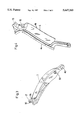
- FIG. 2 shows an enlarged, perspective representation of a first component of the frame of FIG. 1;
- FIG. 3 shows an enlarged, perspective representation of a second component of the frame of FIG. 1;
- FIG. 4 shows an enlarged, perspective representation of a third component of the frame of FIG. 1.
- the frame 1 for the top consists of a front supporting part 2, two rear roof frame parts 3, two main columns 4, two guide rods 5 and two main bearings 6, which serve for retaining as well for fastening the rod assembly elements of the top and in each case are firmly connected to the body.
- roof arches 7 are provided for fastening the material of the top in the usual manner.
- the supporting part 2 is U-shaped and constructed as a one-piece molded part, preferably of pressure diecasting (such as aluminum pressure diecasting).
- pressure diecasting such as aluminum pressure diecasting.
- a front roof frame part 8 Adjoining each side of the peak 9 of the roof, there is a front roof frame part 8. Between the peak 9 of the roof and the front roof frame parts 8, there is in each case a connecting zone 10, which has a receptacle 11 for the locking device for the top.
- a receiving fulcrum 12 which pivotably holds at 42 a connecting element 25, which in turn is connected with the roof arch 7, is provided here.
- the roof arch 7 is stretched in this region over the two front roof frame parts 8.
- the free ends of the front roof frame parts 8 have receiving fulcrums 14 for pivotably connecting at 36 a roof peak guide rod 15.
- elements 16 for a mechanical joint connection with the opening rear roof frame part 3 are disposed here.
- the rear roof frame part 3, in each case adjoining the front roof frame parts 8 can be seen in FIG. 3.
- This rear roof frame part 3 advantageously is also constructed as a one-piece molded part and consists advisably, just as does the supporting part 2, of aluminum pressure diecasting.
- the region of the rear roof frame part 3, facing the front roof frame part 8, has a connecting element 17, which corresponds to the connecting element 16.
- the two roof frame parts 8, 3 can pivotably be connected at 30 to one another mechanically (for example, by means of pivot shafts).
- the region of the rear roof frame part 3, facing the main column 4, has a receiving fulcrum 3a, at which the main column 4 is pivotably connected at 32 with the roof frame part 3.
- a receiving fulcrum 3b is provided, at which the main guide rod 5 is pivotably connected at 40 with the roof frame part 3.
- This main column 4 which can be connected with the rear roof frame parts 3, can be seen in FIG. 4.
- This main column 4 is also advantageously constructed as a one-piece molded part of pressure diecast aluminum.
- the main column 4 has the connecting elements 18 for mechanically fastening to the rear roof frame part 3, as well as receptacles 19 for the roof arch 7 in the middle, which is connected with the main column 4 over a fixed connection, for example, a screwed connection.
- the roof peak guide rod 15 is pivotably connected at 21 with the main column 4.
- the connecting element 16, the receiving fulcrum 14, and the receiving fulcrum 12 are in the form of projections 16a, 14a, 12a respectively which project upwardly from the front roof frame part 8. Also as shown in FIG. 2 each projection 16a, 14a and 12a has an outer end portion at which the pivotal connections 30, 36 and 42 respectively are made.
- the connecting element 17 is in the form of a projection 17a which projects upwardly from the side member 3. Also as shown in FIG. 3 the projection 17a has an outer end portion at which the pivotal connection 30 is made.
- the main column 4 is pivotably fastened at 34 to the main bearing 6 at receiving fulcrum 22 and the main guide rod 5 is pivotally fastened at 38 to the receiving fulcrum 23.
- the main bearing 6 is pivotably mounted at the receiving fulcrum 24 of the rear roof arch 7.
- the main columns 4 have two parts 4a and 4b with the part 4b extending laterally from part 4a.
- pivot connections and pivot fastenings 21, 30, 32, 34, 36, 40, and 42 each constitute pivot means.
- the number of components, of which the inventive frame for the top is composed can be reduced considerably and the assembly of the individual elements to form the frame for the top can be simplified significantly.
- the manufacturing tolerances, improved by these means increase the quality of the top as a whole and improve the possibilities for fastening mounting parts for the top, such as clamping and framing rails.
- the fact that the main components are produced from pressure diecast aluminum primarily means a reduction in weight. This facilitates the handling of the top and also improves the recycling possibilities.
- the supporting part is made from a pressure diecast material
- new design ideas can be realized in that, for example, the supporting part 2 is designed in such a way that it serves to cover the remaining parts of the rod assembly and the material of the top, when the top is down. This may also be of advantage from an aesthetic as well as from a safety point of view.
Abstract
A top for convertibles includes a frame, the side parts of which are disposed symmetrically to the longitudinal axis of the vehicle and comprise front and rear pieces which are pivotably braced over a main column and a main guide rod at a rear main bearing of the chassis frame. The roof peak of the frame lies in a closed position against an upper cross-tie of a windshield frame. The frame is constructed in the front region as a one-piece, shaped carrying part with a U-shaped contour at the basic cross-member of which, forming the roof peak, the front frame parts, which have at their free ends at least one joint connecting element directed towards the main column, are integrally molded over a respective connecting zone as profiled legs.
Description
This application is a continuation of application Ser. No. 08/321,705 filed Oct. 12, 1994, which has been abandoned.
The invention relates to a top for convertibles.
For known convertibles, the frame for the top consists of a welded construction of steel. The assembly, comprising the peak of the roof and the front part of the roof frame, consists here of six parts, the assembly comprising the rear part of the roof frame includes four components and the main column assembly is composed of six parts. In addition, receptacles for the locking devices for the top are constructed separately.
It is an object of the invention to provide a top which is distinguished by a significantly lower number of components for the frame and by a lesser weight which makes the handling easier.
The inventive construction overall makes possible a significant reduction in the number of components comprising the frame for the top and also in the weight. Expensive welding work is no longer required to assemble the frame. As a result, the quality of the frame for the top can be improved overall, since there no longer is a need for manufacturing tolerances which are unavoidable for welding. Moreover, due to the omission of the labor-intensive welding, the top can be produced more inexpensively. Furthermore, the tying to the remaining components of the frame for the top can be configured more simply.
Further details and advantages of the invention arise out of the following specification and out of the drawing, which diagrammatically illustrates an embodiment of the object of the invention.
FIG. 1 shows a perspective, overall view of the inventive frame for the top;
FIG. 2 shows an enlarged, perspective representation of a first component of the frame of FIG. 1;
FIG. 3 shows an enlarged, perspective representation of a second component of the frame of FIG. 1; and
FIG. 4 shows an enlarged, perspective representation of a third component of the frame of FIG. 1.
The frame 1 for the top, generally labeled 1 in FIG. 1, consists of a front supporting part 2, two rear roof frame parts 3, two main columns 4, two guide rods 5 and two main bearings 6, which serve for retaining as well for fastening the rod assembly elements of the top and in each case are firmly connected to the body. In addition, roof arches 7 are provided for fastening the material of the top in the usual manner.
Furthermore, as can be seen particularly from FIG. 2, the supporting part 2 is U-shaped and constructed as a one-piece molded part, preferably of pressure diecasting (such as aluminum pressure diecasting). The peak of the roof 9, which lies against the upper transverse cross-tie of a windshield of the vehicle, forms the basic cross-member.
Adjoining each side of the peak 9 of the roof, there is a front roof frame part 8. Between the peak 9 of the roof and the front roof frame parts 8, there is in each case a connecting zone 10, which has a receptacle 11 for the locking device for the top.
In the region of the free ends of the front roof frame parts 8, there are connecting elements to the remaining components of the frame 1 for the top. For example, a receiving fulcrum 12, which pivotably holds at 42 a connecting element 25, which in turn is connected with the roof arch 7, is provided here. As shown in FIG. 1, the roof arch 7 is stretched in this region over the two front roof frame parts 8. In addition, the free ends of the front roof frame parts 8 have receiving fulcrums 14 for pivotably connecting at 36 a roof peak guide rod 15. Moreover, elements 16 for a mechanical joint connection with the opening rear roof frame part 3 are disposed here.
The rear roof frame part 3, in each case adjoining the front roof frame parts 8 can be seen in FIG. 3. This rear roof frame part 3 advantageously is also constructed as a one-piece molded part and consists advisably, just as does the supporting part 2, of aluminum pressure diecasting. The region of the rear roof frame part 3, facing the front roof frame part 8, has a connecting element 17, which corresponds to the connecting element 16. By these means, the two roof frame parts 8, 3 can pivotably be connected at 30 to one another mechanically (for example, by means of pivot shafts). The region of the rear roof frame part 3, facing the main column 4, has a receiving fulcrum 3a, at which the main column 4 is pivotably connected at 32 with the roof frame part 3. Moreover, a receiving fulcrum 3b is provided, at which the main guide rod 5 is pivotably connected at 40 with the roof frame part 3.
This main column 4, which can be connected with the rear roof frame parts 3, can be seen in FIG. 4. This main column 4 is also advantageously constructed as a one-piece molded part of pressure diecast aluminum. The main column 4 has the connecting elements 18 for mechanically fastening to the rear roof frame part 3, as well as receptacles 19 for the roof arch 7 in the middle, which is connected with the main column 4 over a fixed connection, for example, a screwed connection. In addition, the roof peak guide rod 15 is pivotably connected at 21 with the main column 4.
As shown in FIG. 2, the connecting element 16, the receiving fulcrum 14, and the receiving fulcrum 12 are in the form of projections 16a, 14a, 12a respectively which project upwardly from the front roof frame part 8. Also as shown in FIG. 2 each projection 16a, 14a and 12a has an outer end portion at which the pivotal connections 30, 36 and 42 respectively are made. As shown in FIG. 3, the connecting element 17 is in the form of a projection 17a which projects upwardly from the side member 3. Also as shown in FIG. 3 the projection 17a has an outer end portion at which the pivotal connection 30 is made.
As is evident from FIG. 1, the main column 4 is pivotably fastened at 34 to the main bearing 6 at receiving fulcrum 22 and the main guide rod 5 is pivotally fastened at 38 to the receiving fulcrum 23. Moreover, the main bearing 6 is pivotably mounted at the receiving fulcrum 24 of the rear roof arch 7. As shown in FIGS. 1 and 4, the main columns 4 have two parts 4a and 4b with the part 4b extending laterally from part 4a.
The pivot connections and pivot fastenings 21, 30, 32, 34, 36, 40, and 42 each constitute pivot means.
As is evident from the preceding, the number of components, of which the inventive frame for the top is composed, can be reduced considerably and the assembly of the individual elements to form the frame for the top can be simplified significantly. The manufacturing tolerances, improved by these means, increase the quality of the top as a whole and improve the possibilities for fastening mounting parts for the top, such as clamping and framing rails. The fact that the main components are produced from pressure diecast aluminum primarily means a reduction in weight. This facilitates the handling of the top and also improves the recycling possibilities. Moreover, particularly because the supporting part is made from a pressure diecast material, new design ideas can be realized in that, for example, the supporting part 2 is designed in such a way that it serves to cover the remaining parts of the rod assembly and the material of the top, when the top is down. This may also be of advantage from an aesthetic as well as from a safety point of view.
Aside from pressure diecast aluminum, other lightweight materials, such as magnesium alloys or composites (plastics or fiberglass-reinforced plastics) can also be used to make the components of the top, since their properties, with respect to weight and strength, are similar to those of pressure diecast aluminum.
Claims (31)
1. A top for a convertible vehicle having a front, a rear and a longitudinal axis extending from front to rear, said top comprising a molded one-piece U-shaped frame member having a front section extending transversely of said longitudinal axis and two elongated spaced side sections extending rearwardly from said front section, each of said side sections having a first connecting element, said first connecting element being integrally formed with said molded one-piece U-shaped frame member, a pair of side members, first pivot means pivotably connecting said side members to said first connecting element of said elongated side sections of said one-piece U-shaped frame member for pivotal movement about a generally horizontal axis, a pair of main column means, said pair of main column means having second pivot means pivotably mounting said pair of main column means on said vehicle, and third pivot means pivotably connecting said side members to said main column means for pivotal movement about a generally horizontal axis, said two spaced elongated side sections, said pair of side members, and said pair of main column means each being disposed on opposite sides of said longitudinal axis of said vehicle.
2. A top for a convertible vehicle according to claim 1 wherein each of said main column means comprises a main bearing support and a main column member, said second pivot means pivotably supporting said main column member on said main bearing support.
3. A top for a convertible vehicle according to claim 2 wherein each of said side sections has a first receiving fulcrum integrally formed with said molded one-piece U-shaped frame member, and further comprising elongated guide rods juxtaposed to said side members, fourth pivot means pivotably connecting said guide rods to said first receiving fulcrum on each of said elongated side sections of said one-piece U-shaped member and fifth pivot means pivotably connecting said guide rods to said main column members.
4. A top for a convertible vehicle according to claim 3 wherein said elongated guide rods are designated first guide rods, further comprising elongated second guide rods juxtaposed to said main column members, sixth pivot means pivotably connecting said elongated second guide rods to said side members, and seventh pivot means pivotably connecting said elongated second guide rods to said main bearing support.
5. A top for a convertible vehicle having a front, a rear and a longitudinal axis extending from front to rear, said top comprising a molded one-piece U-shaped frame member having a front section extending transversely of said longitudinal axis and two elongated spaced side sections extending rearwardly from said front section, each of said side sections having a first connecting element, said first connecting element being integrally formed with said molded one-piece U-shaped frame member, a pair of side members, first pivot means pivotably connecting said side members to said first connecting element of said elongate side sections of said one-piece U-shaped frame member for pivotal movement about a first axis, a pair of main column means, said pair of main column means having second pivot means pivotably mounting said pair of main column means on said vehicle for pivotal movement about a second axis, and third pivot means for pivotably connecting said side members to said main column means for pivotal movement about a third axis, said first, second and third axes being substantially parallel to one another, said two spaced elongated side sections, said pair of side members, and said pair of main column means each being disposed on opposite sides of said longitudinal axis of said vehicle.
6. In a top for a convertible vehicle having a front, a rear and a longitudinal axis extending from front to rear, the combination comprising:
a molded, one-piece, U-shaped frame member lying against an upper transverse cross-tie of a windshield of the vehicle and directly connected to a roof arch, said frame member having a front section extending transversely of said longitudinal axis and two elongated spaced side sections extending rearwardly from said front section;
each of said side sections having a first connecting element;
a pair of side members; and
first pivot means pivotally connecting said first connecting element to said side members.
7. In a top for a convertible vehicle according to claim 6 wherein said first connecting element on said side sections of said molded one-piece U-shaped frame member comprises a projection projecting upwardly from said elongated side section, said elongated side section and said projection being integral with said molded one-piece U-shaped frame member, said projection having an outer end portion, said first pivot means being located at said outer end portion of said projection.
8. In a top for a convertible vehicle according to claim 6 wherein each of said side sections has a first receiving fulcrum integrally formed with said molded one-piece U-shaped frame member, said first receiving fulcrum comprising a projection projecting upwardly from said side sections, said projections being integral with said side sections of said molded one-piece U-shaped frame member.
9. In a top for a convertible vehicle according to claim 6 wherein said first connecting element on each of said side sections comprises a first projection projecting upwardly from said elongated side sections, said first projection being an integral part of said molded one-piece U-shaped supporting member, said first projection having a first outer end portion, said first pivot means being located at said first outer end portion of said first projection, each of said side sections having a first receiving fulcrum integrally formed with said molded one-piece U-shaped frame member, said first receiving fulcrum comprising a second projection projecting upwardly from said elongated side sections, said elongated side section and said second projection each being integral parts of said molded one-piece U-shaped frame member, said second projection having a second outer end portion, and second pivot means being located on said second outer end portion of said second projection.
10. A top for a convertible vehicle according to claim 6 wherein said molded one-piece U-shaped frame member is molded from a material selected from the group consisting of diecast aluminum, magnesium alloy, fiber-reinforced plastic, and plastic.
11. In a top for a convertible vehicle according to claim 9 wherein said molded one-piece U-shaped frame member including said first connecting element and said first receiving fulcrum are all molded from a material selected from the group consisting of diecast aluminum, magnesium alloy, fiber-reinforced plastic, and plastic.
12. In a top for a convertible vehicle according to claim 9 further comprising a second receiving fulcrum on each of said side sections of said molded one-piece U-shaped frame member, said second receiving fulcrum including a third projection projecting upwardly from said elongated side section, said elongated side section and said third projection being integral parts of said molded one-piece U-shaped frame member, said third projection having a third outer end portion, third pivot means located at said third outer end portion, and said roof arch pivotally connected to said third pivot means.
13. In a top for a convertible vehicle according to claim 12 wherein said molded one-piece U-shaped frame member including said first connecting element, said first receiving fulcrum and said second receiving fulcrum are all molded from a material selected from the group consisting of diecast aluminum, magnesium alloy, fiber-reinforced plastic, and plastic.
14. In a top for a convertible vehicle according to claim 6 wherein said vehicle has a locking device for locking said top to said vehicle, said molded one-piece U-shaped frame member having a receptacle for receiving said locking device.
15. In a top for a convertible automobile according to claim 9 further comprising:
a main bearing support mounted on said vehicle;
third pivot means pivotally connecting main columns to said main bearing support;
a first guide rod;
said first guide rod being pivotably connected to said one-piece U-shaped frame member at said second pivot means on said second outer end portion of said second projection of said one-piece U-shaped frame member; and
fourth pivot means pivotally connecting said first guide rod to said main columns.
16. In a top for a convertible vehicle according to claim 15 further comprising:
a second guide rod;
fifth pivot means pivotally connecting said second guide rod to said main bearing support; and
sixth pivot means pivotally connecting said second guide rod to said side member.
17. A top for a convertible vehicle having a front, a rear and a longitudinal axis extending from front to rear, said top comprising:
a molded, one-piece, U-shaped frame member having a front section extending transversely of said longitudinal axis and two elongated spaced side sections extending rearwardly from said front section;
each of said side sections having a first receiving fulcrum and a first connecting element;
a pair of molded one-piece side members;
each of said side members having a second receiving fulcrum and a second connecting element;
first pivot means pivotally connecting said first connecting element and said second connecting element to thereby pivotally connect said side sections of said molded one-piece U-shaped frame member to said molded one-piece side member;
a pair of molded one-piece main columns;
second pivot means pivotally connecting said molded one-piece main columns and said second receiving fulcrum to thereby pivotably connect said molded one-piece main column to said molded one-piece side member;
a main bearing support mounted on said vehicle;
third pivot means pivotally connecting said molded one-piece main columns to said main bearing support;
a first guide rod;
fourth pivot means pivotally connecting said first guide rod to said one-piece U-shaped frame member;
fifth pivot means pivotally connecting said first guide rod to said molded one-piece main columns;
a second guide rod;
sixth pivot means pivotally connecting said second guide rod to said main bearing support; and
seventh pivot means pivotally connecting said second guide rod to said molded one-piece side member.
18. A top for a convertible vehicle according to claim 17 wherein said second connecting element on said side members comprise a projection projecting upwardly from said side members, said side members and said projection each being an integral part of said molded one-piece side member, said projection having an outer end portion, said first pivot means being located at said outer end portion of said projection.
19. A top for a convertible vehicle according to claim 16 wherein said molded one-piece main columns each have an elongate first part and a second part extending laterally from said first part, said first part and said second part being integral parts of said molded one-piece main columns.
20. A top for a convertible vehicle according to claim 16 wherein each of said molded one-piece U-shaped frame member, said molded one-piece side members and said molded one-piece main columns are molded from a material selected from the group consisting of diecast aluminum, magnesium alloy, fiber-reinforced plastic and plastic.
21. A top for a convertible vehicle having a front, a rear and a longitudinal axis extending from front to rear, said top comprising:
a molded, one-piece, U-shaped frame member having a front section extending transversely of said longitudinal axis and two elongated spaced side sections extending rearwardly from said front section;
each of said side sections having a first receiving fulcrum and a first connecting element;
a pair of molded one-piece side members;
each of said side members having a second receiving fulcrum and a second connecting element;
first pivot means pivotally connecting said first connecting element and said second connecting element to thereby pivotally connect said side sections of said molded one-piece U-shaped frame member to said molded one-piece side member;
a pair of molded one-piece main columns;
second pivot means pivotally connecting said molded one-piece main columns and said second receiving fulcrum to thereby pivotably connect said molded one-piece main column to said molded one-piece side member;
a main bearing support mounted on said vehicle, said main bearing support having a fourth receiving fulcrum and a fifth receiving fulcrum;
third pivot means pivotally connecting said molded one-piece main columns to said fourth receiving fulcrum to thereby pivotably connect said molded one-piece main columns to said main bearing support;
a first guide rod;
a fourth pivot means pivotally connecting said first guide rod to said first receiving fulcrum to thereby pivotably connect said first guide rod to said side sections of said molded one-piece U-shaped frame member;
fifth pivot means pivotally connecting said first guide rod to said molded one-piece main columns to thereby pivotably connect said first guide rod to said molded one-piece main columns;
a second guide rod;
sixth pivot means pivotally connecting said second guide rod to said fifth receiving fulcrum to thereby pivotably connect said second guide rod to said main bearing support; and
seventh pivot means pivotally connecting said second guide rod to a third receiving fulcrum to thereby pivotably connect said second guide rod to said molded one-piece side member.
22. A top for a convertible vehicle according to claim 21 wherein said first receiving fulcrum on said side sections of said molded one-piece U-shaped frame member comprises a projection projecting upwardly from said side sections, said projections being integral with said side sections of said molded one-piece U-shaped frame member.
23. A top for a convertible vehicle according to claim 21 wherein said first connecting element on said side sections of said molded one-piece U-shaped frame member part comprises a projection projecting upwardly from said side sections, said projections being integral with said side sections of said molded one-piece U-shaped frame member.
24. A top for a convertible vehicle according to claim 21 wherein said first connecting element on said side sections of said molded one-piece U-shaped frame member comprises a projection projecting upwardly from said elongated side section, said elongated side section and said projection being integral with said molded one-piece U-shaped frame member, said projection having an outer end portion, said first pivot means being located at said outer end portion of said projection.
25. A top for a convertible vehicle according to claim 21 wherein said second connecting element on said side members comprise a projection projecting upwardly from said side members, said side members and said projection each being an integral part of said molded one-piece side member, said projection having an outer end portion, said first pivot means being located at said outer end portion of said projection.
26. A top for a convertible vehicle according to claim 21 further comprising a sixth receiving fulcrum on each of said side sections of said molded one-piece U-shaped frame member, said sixth receiving fulcrum including a projection projecting upwardly from said side sections, said side sections and said projection having an outer end portion, said sixth receiving fulcrum having eighth pivot means at said outer end of said projection, and a roof arch pivotally connected at said eight pivotal means.
27. A top for a convertible vehicle according to claim 21 wherein said first connecting element on each of said side sections comprises a first projection projecting upwardly from said elongated side sections, said first projection being an integral part of said molded one-piece U-shaped supporting member, said first projection having a first outer end portion, said first pivot means being located at said first outer end portion of said first projection, said first receiving fulcrum comprising a second projection projecting upwardly from said elongated side sections, said elongated side section and said second projection each being integral parts of said molded one-piece U-shaped frame member, said second projection having a second outer end portion, said fourth pivot means being located on said second outer end portion of said second projection.
28. A top for a convertible vehicle according to claim 21 wherein said molded one-piece main columns each have an elongate first part and a second part extending laterally from said first part, said first part and said second part being integral parts of said molded one-piece main columns.
29. A top for a convertible vehicle according to claim 21 further comprising a roof arch, and connecting means fixedly connecting said roof arch on said main columns.
30. A top for a convertible vehicle according to claim 21 wherein at least one of said molded one-piece U-shaped frame member, said molded one-piece side members and said molded one-piece main columns are molded from a material selected from the group consisting of diecast aluminum, magnesium alloy, fiber-reinforced plastic, and plastic.
31. A top for a convertible vehicle according to claim 21 wherein each of said molded one-piece U-shaped frame member, said molded one-piece side members and said molded one-piece main columns are molded from a material selected from the group consisting of diecast aluminum, magnesium alloy, fiber-reinforced plastic and plastic.
Priority Applications (1)
| Application Number | Priority Date | Filing Date | Title |
|---|---|---|---|
| US08/625,927 US5667269A (en) | 1993-10-15 | 1996-04-01 | Three section convertible top |
Applications Claiming Priority (4)
| Application Number | Priority Date | Filing Date | Title |
|---|---|---|---|
| DE9315758U DE9315758U1 (en) | 1993-10-15 | 1993-10-15 | Convertible top |
| DE9315758.4U | 1993-10-15 | ||
| US32170594A | 1994-10-12 | 1994-10-12 | |
| US08/625,927 US5667269A (en) | 1993-10-15 | 1996-04-01 | Three section convertible top |
Related Parent Applications (1)
| Application Number | Title | Priority Date | Filing Date |
|---|---|---|---|
| US32170594A Continuation | 1993-10-15 | 1994-10-12 |
Publications (1)
| Publication Number | Publication Date |
|---|---|
| US5667269A true US5667269A (en) | 1997-09-16 |
Family
ID=6899477
Family Applications (1)
| Application Number | Title | Priority Date | Filing Date |
|---|---|---|---|
| US08/625,927 Expired - Lifetime US5667269A (en) | 1993-10-15 | 1996-04-01 | Three section convertible top |
Country Status (5)
| Country | Link |
|---|---|
| US (1) | US5667269A (en) |
| EP (1) | EP0648630B1 (en) |
| JP (1) | JP3014597B2 (en) |
| DE (2) | DE9315758U1 (en) |
| ES (1) | ES2096384T3 (en) |
Cited By (23)
| Publication number | Priority date | Publication date | Assignee | Title |
|---|---|---|---|---|
| US5903119A (en) * | 1997-08-22 | 1999-05-11 | Asc Incorporated | Convertible roof actuation mechanism |
| US5971470A (en) * | 1996-06-07 | 1999-10-26 | Dr. Ing. H.C.F. Porsche Ag | Folding top for a passenger car |
| US5998948A (en) * | 1998-05-29 | 1999-12-07 | Acs Incorporated | Convertible roof actuation mechanism |
| US6042174A (en) | 1997-08-22 | 2000-03-28 | Asc Incorporated | Latching and control apparatus for an automotive vehicle convertible roof |
| US6048021A (en) * | 1998-04-25 | 2000-04-11 | Dura Convertible Systems | Convertible top mechanism with powered rear row |
| US6095589A (en) * | 1998-02-27 | 2000-08-01 | Valmet Auotmotive Oy | Vehicle and folding top for a vehicle |
| US6237986B1 (en) * | 1998-11-14 | 2001-05-29 | Cts Fahrzeug-Dachsysteme Gmbh | Folding hood for a motor vehicle |
| US6416111B1 (en) * | 2001-02-08 | 2002-07-09 | Cts Fahrzeug Dachsysteme Gmbh | Cross folding convertible top |
| US6464284B2 (en) | 2000-09-13 | 2002-10-15 | Cts Fahrzeug Dachsysteme Gmbh | Compact top stack linkage |
| US6499793B2 (en) * | 1999-12-31 | 2002-12-31 | Wilhelm Karmann Gmbh | Folding for a convertible vehicle |
| US6523881B1 (en) * | 1999-09-06 | 2003-02-25 | Webasto Vehicle Systems International Gmbh | Folding roof for a convertible |
| US20040130188A1 (en) * | 2002-11-06 | 2004-07-08 | Stevens Michael C. | Releasable header for vehicle soft tops |
| US6802554B1 (en) | 2003-10-15 | 2004-10-12 | Cts Fahrzeug-Dachsysteme Gmbh | Cross folding convertible top with one piece one bow |
| WO2005084289A3 (en) * | 2004-02-27 | 2005-10-20 | Cts Fahrzeug Dachsysteme Gmbh | Injection molded magnesium convertible top stack having a common pivot for a pivot link, center rail and rear rail |
| US6957842B1 (en) | 2004-04-30 | 2005-10-25 | Asc Incorporated | Convertible roof bow tensioning apparatus |
| US20070187982A1 (en) * | 2003-10-24 | 2007-08-16 | Klaus Licher | Convertible vehicle |
| US20080066671A1 (en) * | 2006-08-02 | 2008-03-20 | The Talaria Company, Llc | Convertible top for yacht |
| US20090008968A1 (en) * | 2004-04-02 | 2009-01-08 | Wilhelm Karmann Gmbh | Closure Device for a Convertible Top of a Convertible Vehicle |
| US20090261615A1 (en) * | 2007-10-15 | 2009-10-22 | Magna Car Top Systems Gmbh | Injection molded magnesium link and method of making an injection molded magnesium link |
| US20100156136A1 (en) * | 2008-12-22 | 2010-06-24 | Wilhelm Karmann Gmbh | Convertible top with in-folding side rails |
| US20150151619A1 (en) * | 2013-12-04 | 2015-06-04 | Webasto-Edscha Cabrio GmbH | Convertible top with link arrangements for adjusting a convertible top element |
| US10220689B2 (en) * | 2017-06-30 | 2019-03-05 | Webasto SE | Top of a vehicle comprising locking means |
| USD1002493S1 (en) * | 2022-02-16 | 2023-10-24 | Bestop, Inc. | Convertible top frame |
Families Citing this family (5)
| Publication number | Priority date | Publication date | Assignee | Title |
|---|---|---|---|---|
| DE4441666C1 (en) | 1994-11-23 | 1995-12-14 | Porsche Ag | Collapsible roof for vehicle |
| DE29617882U1 (en) * | 1996-10-15 | 1998-02-19 | Karmann Gmbh W | Cabriolet vehicle |
| JP4639844B2 (en) * | 2005-02-25 | 2011-02-23 | マツダ株式会社 | Top frame structure for vehicle hood |
| DE102009020941A1 (en) | 2009-05-12 | 2010-11-25 | Magna Car Top Systems Gmbh | Roof cap for convertible top of passenger car, is arranged in front area of convertible top movable between closed position and open position and cooperates with windshield frame of structure of passenger car |
| DE102011016778A1 (en) | 2011-04-12 | 2012-10-18 | Magna Car Top Systems Gmbh | Actuator for U-shaped roof cover of movable roof of cabriolet vehicle, has end-side guide bar whose front pivotal lever is pivotally connected with cover by connecting rod that is pointed toward cover |
Citations (10)
| Publication number | Priority date | Publication date | Assignee | Title |
|---|---|---|---|---|
| US1952252A (en) * | 1933-05-24 | 1934-03-27 | Derham Custom Body Company | Collapsible top for vehicles |
| US2596309A (en) * | 1949-05-17 | 1952-05-13 | Urich William | Supplemental top for automobiles |
| CA740339A (en) * | 1966-08-09 | W. Brydon Edward | Convertible top interlock | |
| US3473842A (en) * | 1967-06-27 | 1969-10-21 | Ford Motor Co | Convertible top mechanism |
| US3994524A (en) * | 1973-05-30 | 1976-11-30 | Daimler-Benz Aktiengesellschaft | Control linkage for foldable top motor vehicles |
| US4261615A (en) * | 1979-09-20 | 1981-04-14 | Deaver Dann T | Convertible top structure and method |
| US4440436A (en) * | 1982-05-06 | 1984-04-03 | Giddens Marian S | Convertible top for motorcycles and snowmobiles |
| US4747635A (en) * | 1987-03-02 | 1988-05-31 | Cars & Concepts, Inc. | Vehicle convertible top having sail flap tensioner |
| US4991902A (en) * | 1989-02-08 | 1991-02-12 | Daimler-Benz Ag | Folding top covering for a folding top of a vehicle |
| US5207474A (en) * | 1991-07-04 | 1993-05-04 | Wilhelm Karmann Gmbh | Folding top for a passenger car with folding roof |
Family Cites Families (12)
| Publication number | Priority date | Publication date | Assignee | Title |
|---|---|---|---|---|
| SU608672A1 (en) * | 1975-09-29 | 1978-05-30 | Московский Автомобильный Завод Имени И.А.Лихачева (Производственное Объединение Зил) | Foldable tent for vehicle |
| DE8030653U1 (en) * | 1980-11-15 | 1981-05-27 | Daffner, Johann, 8413 Batzhausen | HARDTOP FOR MOTOR VEHICLES |
| DE3127524C2 (en) * | 1981-07-11 | 1983-04-28 | Dr.Ing.H.C. F. Porsche Ag, 7000 Stuttgart | "Folding top for passenger cars" |
| DE3405920C2 (en) * | 1984-02-18 | 1985-12-12 | Daimler-Benz Ag, 7000 Stuttgart | Folding roofs for vehicles, in particular for passenger cars |
| US4573732A (en) * | 1984-04-30 | 1986-03-04 | Muscat Peter P | Convertible top frame |
| DE3507800A1 (en) * | 1985-03-05 | 1986-09-11 | skv-styling Cabriolet- und Fahrzeugbau GmbH & Co KG, 6520 Worms | Passenger car |
| DE3724532C1 (en) * | 1987-07-24 | 1988-11-10 | Daimler Benz Ag | Hood frame of a folding roof for vehicles |
| DE3809197A1 (en) * | 1988-03-18 | 1989-09-28 | Bayerische Motoren Werke Ag | FOLDING CANOPY OF A MOTOR VEHICLE |
| DE8909984U1 (en) * | 1989-08-21 | 1989-10-05 | Ostermann, Wilfried, 4530 Ibbenbueren, De | |
| DE9017360U1 (en) * | 1990-01-17 | 1991-03-21 | Wilhelm Karmann Gmbh, 4500 Osnabrueck, De | |
| DE9108242U1 (en) * | 1991-07-04 | 1992-11-05 | Wilhelm Karmann Gmbh, 4500 Osnabrueck, De | |
| GB2271088A (en) * | 1992-08-19 | 1994-04-06 | Mascotech Automotive Operation | Vehicle convertible top. |
-
1993
- 1993-10-15 DE DE9315758U patent/DE9315758U1/en not_active Expired - Lifetime
-
1994
- 1994-07-23 DE DE59401077T patent/DE59401077D1/en not_active Expired - Lifetime
- 1994-07-23 ES ES94111513T patent/ES2096384T3/en not_active Expired - Lifetime
- 1994-07-23 EP EP94111513A patent/EP0648630B1/en not_active Expired - Lifetime
- 1994-10-14 JP JP6249691A patent/JP3014597B2/en not_active Expired - Fee Related
-
1996
- 1996-04-01 US US08/625,927 patent/US5667269A/en not_active Expired - Lifetime
Patent Citations (10)
| Publication number | Priority date | Publication date | Assignee | Title |
|---|---|---|---|---|
| CA740339A (en) * | 1966-08-09 | W. Brydon Edward | Convertible top interlock | |
| US1952252A (en) * | 1933-05-24 | 1934-03-27 | Derham Custom Body Company | Collapsible top for vehicles |
| US2596309A (en) * | 1949-05-17 | 1952-05-13 | Urich William | Supplemental top for automobiles |
| US3473842A (en) * | 1967-06-27 | 1969-10-21 | Ford Motor Co | Convertible top mechanism |
| US3994524A (en) * | 1973-05-30 | 1976-11-30 | Daimler-Benz Aktiengesellschaft | Control linkage for foldable top motor vehicles |
| US4261615A (en) * | 1979-09-20 | 1981-04-14 | Deaver Dann T | Convertible top structure and method |
| US4440436A (en) * | 1982-05-06 | 1984-04-03 | Giddens Marian S | Convertible top for motorcycles and snowmobiles |
| US4747635A (en) * | 1987-03-02 | 1988-05-31 | Cars & Concepts, Inc. | Vehicle convertible top having sail flap tensioner |
| US4991902A (en) * | 1989-02-08 | 1991-02-12 | Daimler-Benz Ag | Folding top covering for a folding top of a vehicle |
| US5207474A (en) * | 1991-07-04 | 1993-05-04 | Wilhelm Karmann Gmbh | Folding top for a passenger car with folding roof |
Cited By (40)
| Publication number | Priority date | Publication date | Assignee | Title |
|---|---|---|---|---|
| US5971470A (en) * | 1996-06-07 | 1999-10-26 | Dr. Ing. H.C.F. Porsche Ag | Folding top for a passenger car |
| US6042174A (en) | 1997-08-22 | 2000-03-28 | Asc Incorporated | Latching and control apparatus for an automotive vehicle convertible roof |
| US5903119A (en) * | 1997-08-22 | 1999-05-11 | Asc Incorporated | Convertible roof actuation mechanism |
| US6095589A (en) * | 1998-02-27 | 2000-08-01 | Valmet Auotmotive Oy | Vehicle and folding top for a vehicle |
| US6048021A (en) * | 1998-04-25 | 2000-04-11 | Dura Convertible Systems | Convertible top mechanism with powered rear row |
| US5998948A (en) * | 1998-05-29 | 1999-12-07 | Acs Incorporated | Convertible roof actuation mechanism |
| US6237986B1 (en) * | 1998-11-14 | 2001-05-29 | Cts Fahrzeug-Dachsysteme Gmbh | Folding hood for a motor vehicle |
| US6523881B1 (en) * | 1999-09-06 | 2003-02-25 | Webasto Vehicle Systems International Gmbh | Folding roof for a convertible |
| US6499793B2 (en) * | 1999-12-31 | 2002-12-31 | Wilhelm Karmann Gmbh | Folding for a convertible vehicle |
| US6464284B2 (en) | 2000-09-13 | 2002-10-15 | Cts Fahrzeug Dachsysteme Gmbh | Compact top stack linkage |
| US6416111B1 (en) * | 2001-02-08 | 2002-07-09 | Cts Fahrzeug Dachsysteme Gmbh | Cross folding convertible top |
| US20040130188A1 (en) * | 2002-11-06 | 2004-07-08 | Stevens Michael C. | Releasable header for vehicle soft tops |
| US6932423B2 (en) | 2002-11-06 | 2005-08-23 | Bestop, Inc. | Releasable header for vehicle soft tops |
| US6802554B1 (en) | 2003-10-15 | 2004-10-12 | Cts Fahrzeug-Dachsysteme Gmbh | Cross folding convertible top with one piece one bow |
| US20070187982A1 (en) * | 2003-10-24 | 2007-08-16 | Klaus Licher | Convertible vehicle |
| US7413236B2 (en) * | 2003-10-24 | 2008-08-19 | Wilhelm Karmann Gmbh | Convertible vehicle |
| WO2005084289A3 (en) * | 2004-02-27 | 2005-10-20 | Cts Fahrzeug Dachsysteme Gmbh | Injection molded magnesium convertible top stack having a common pivot for a pivot link, center rail and rear rail |
| EP1727695A2 (en) * | 2004-02-27 | 2006-12-06 | CTS Fahrzeug Dachsysteme GmbH | Injection molded magnesium convertible top stack having a common pivot for a pivot link, center rail and rear rail |
| US20100109374A1 (en) * | 2004-02-27 | 2010-05-06 | Magna Car Top Systems Of America, Inc. | Convertible Top Having a Common Pivot for a Pivot Link for Two Bows and a Tensioning Link for a Rear Rail |
| US8398147B2 (en) | 2004-02-27 | 2013-03-19 | Magna Car Top Systems Gmbh | Convertible top having a common pivot for a pivot link for two bows and a tensioning link for a rear rail |
| US8302311B2 (en) | 2004-02-27 | 2012-11-06 | Magna Car Top Systems Gmbh | Convertible top stack having a triple pivot for a pivot link, center rail, and rear rail |
| EP1727695A4 (en) * | 2004-02-27 | 2010-06-02 | Cts Fahrzeug Dachsysteme Gmbh | Injection molded magnesium convertible top stack having a common pivot for a pivot link, center rail and rear rail |
| US20100109375A1 (en) * | 2004-02-27 | 2010-05-06 | Magna Car Top Systems Of America, Inc. | Convertible Top Stack Having a Triple Pivot for a Pivot Link, Center Rail, and Rear Rail |
| US20090008968A1 (en) * | 2004-04-02 | 2009-01-08 | Wilhelm Karmann Gmbh | Closure Device for a Convertible Top of a Convertible Vehicle |
| US20060061130A1 (en) * | 2004-04-30 | 2006-03-23 | Asc Incorporated | Convertible roof bow tensioning apparatus |
| US20050242615A1 (en) * | 2004-04-30 | 2005-11-03 | Garska Bradley R | Convertible roof bow tensioning apparatus |
| US6957842B1 (en) | 2004-04-30 | 2005-10-25 | Asc Incorporated | Convertible roof bow tensioning apparatus |
| US7380863B2 (en) | 2004-04-30 | 2008-06-03 | Specialty Vehicle Aquisition Corp. | Convertible roof bow tensioning apparatus |
| US20080066671A1 (en) * | 2006-08-02 | 2008-03-20 | The Talaria Company, Llc | Convertible top for yacht |
| US20100107961A1 (en) * | 2006-08-02 | 2010-05-06 | The Talaria Company, Llc | Convertible top for yacht |
| US7958839B2 (en) | 2006-08-02 | 2011-06-14 | The Talaria Company, Llc | Convertible top for yacht |
| US7669542B2 (en) | 2006-08-02 | 2010-03-02 | The Talaria Company, Llc | Convertible top for yacht |
| US8136864B2 (en) | 2007-10-15 | 2012-03-20 | Magna Car Top Systems Gmbh | Injection molded magnesium link and method of making an injection molded magnesium link |
| US20090261615A1 (en) * | 2007-10-15 | 2009-10-22 | Magna Car Top Systems Gmbh | Injection molded magnesium link and method of making an injection molded magnesium link |
| US20100156136A1 (en) * | 2008-12-22 | 2010-06-24 | Wilhelm Karmann Gmbh | Convertible top with in-folding side rails |
| US7959208B2 (en) * | 2008-12-22 | 2011-06-14 | Wilhelm Karmann Gmbh | Convertible top with in-folding side rails |
| US20150151619A1 (en) * | 2013-12-04 | 2015-06-04 | Webasto-Edscha Cabrio GmbH | Convertible top with link arrangements for adjusting a convertible top element |
| US9108494B2 (en) * | 2013-12-04 | 2015-08-18 | Webasto-Edscha Cabrio GmbH | Convertible top with link arrangements for adjusting a convertible top element |
| US10220689B2 (en) * | 2017-06-30 | 2019-03-05 | Webasto SE | Top of a vehicle comprising locking means |
| USD1002493S1 (en) * | 2022-02-16 | 2023-10-24 | Bestop, Inc. | Convertible top frame |
Also Published As
| Publication number | Publication date |
|---|---|
| EP0648630A1 (en) | 1995-04-19 |
| DE59401077D1 (en) | 1997-01-02 |
| JPH07156660A (en) | 1995-06-20 |
| JP3014597B2 (en) | 2000-02-28 |
| EP0648630B1 (en) | 1996-11-20 |
| ES2096384T3 (en) | 1997-03-01 |
| DE9315758U1 (en) | 1993-12-23 |
Similar Documents
| Publication | Publication Date | Title |
|---|---|---|
| US5667269A (en) | Three section convertible top | |
| US4542934A (en) | Front body construction for motor vehicle | |
| US4618163A (en) | Automotive chassis | |
| US5466005A (en) | Motor vehicle | |
| US5611569A (en) | Vehicle subframe assembly | |
| US4487447A (en) | Convertible top for passenger motor vehicles | |
| JP2000118440A (en) | Center pillar structure | |
| JP5306618B2 (en) | Automobile having a roll bar device | |
| JP3480289B2 (en) | Body rear structure | |
| US6267437B1 (en) | Front pillar arrangement for a motor vehicle body frame | |
| JP2000333769A (en) | Seat back frame | |
| EP0823363A3 (en) | Body structure for a motor vehicle | |
| US6139093A (en) | Front end-to-body side joint for automotive vehicle | |
| US7938446B2 (en) | Vehicle body of a convertible vehicle | |
| EP1234751B1 (en) | Front structure for a motor vehicle | |
| JPH07164845A (en) | Linking part structure of rear suspension | |
| EP1083071B1 (en) | Convertible vehicle soft top element and convertible vehicle soft top | |
| US6872463B2 (en) | Reinforcing rod for body and/or chassis elements for a motor vehicle | |
| JP3364706B2 (en) | Reinforcement structure of the joint between the vehicle rear pillar and the rear roof rail | |
| JPS63176785A (en) | Upper body structure of automobile | |
| JP2949885B2 (en) | Rear frame structure of vehicle body | |
| JP4359613B2 (en) | Automobile front pillar structure | |
| JP2707860B2 (en) | Body frame structure | |
| JP3316787B2 (en) | Rear pillar reinforcement structure for vehicles | |
| KR950009030Y1 (en) | Upper body structure of an automotive vehicle |
Legal Events
| Date | Code | Title | Description |
|---|---|---|---|
| STCF | Information on status: patent grant |
Free format text: PATENTED CASE |
|
| FPAY | Fee payment |
Year of fee payment: 4 |
|
| FPAY | Fee payment |
Year of fee payment: 8 |
|
| FPAY | Fee payment |
Year of fee payment: 12 |