US5644491A - Self contained multi-function engine monitor and timer for providing engine running time, job time, service time and tachometer functions - Google Patents
Self contained multi-function engine monitor and timer for providing engine running time, job time, service time and tachometer functions Download PDFInfo
- Publication number
- US5644491A US5644491A US08/189,321 US18932194A US5644491A US 5644491 A US5644491 A US 5644491A US 18932194 A US18932194 A US 18932194A US 5644491 A US5644491 A US 5644491A
- Authority
- US
- United States
- Prior art keywords
- engine
- rpm
- time
- monitor
- timer
- Prior art date
- Legal status (The legal status is an assumption and is not a legal conclusion. Google has not performed a legal analysis and makes no representation as to the accuracy of the status listed.)
- Expired - Lifetime
Links
Images


Classifications
-
- G—PHYSICS
- G07—CHECKING-DEVICES
- G07C—TIME OR ATTENDANCE REGISTERS; REGISTERING OR INDICATING THE WORKING OF MACHINES; GENERATING RANDOM NUMBERS; VOTING OR LOTTERY APPARATUS; ARRANGEMENTS, SYSTEMS OR APPARATUS FOR CHECKING NOT PROVIDED FOR ELSEWHERE
- G07C3/00—Registering or indicating the condition or the working of machines or other apparatus, other than vehicles
- G07C3/02—Registering or indicating working or idle time only
- G07C3/04—Registering or indicating working or idle time only using counting means or digital clocks
Definitions
- This invention relates generally to an engine monitor, and more particularly to a self-contained multi-function engine monitor and timer that provides engine running time, job time, service time, and tachometer functions.
- U.S. Pat. No. 5,257,190 describes an engine management system for powered vehicles that senses a large number of parameters of the engine powered vehicle and performs real time management for identifying system inefficiencies and sub-systems requiring repair.
- the device includes a microprocessor and an analogue to digital converter connected between a plurality of inputs and the microprocessor to convert the analogue output of input sensors into digital output for the microprocessor.
- a large number of direct real time inputs is described including RPM and the system includes a clock for implementing timing functions.
- U.S. Pat. No. 4,853,859 shows a device for detecting operating conditions of a vehicle.
- the apparatus measures RPM and includes a clock for discriminating the entire working time of an engine into engine idling, operation of the vehicle and rest time.
- U.S. Pat. No. 4,551,803 describes an engine monitoring system having a multiplicity of inputs and a clock for monitoring a number of engine parameters to perform various functions including speed metering, odometer, trip meter, tachometer, and the like.
- An engine monitor that provides all of these characteristics is even more useful if it is small, self-contained, and easily fitted to an existing engine on an existing piece of equipment in a manner that can provide the foregoing functions in a cost effective, low maintenance, easy to install unit.
- an engine monitor in accordance with the present invention that includes, in a self-contained preferably sealed unit, a spark sensor, inductively and capacitively coupled through the case to a spark pick up wire, a timer, and a running time detector, responsive to inputs from the spark pick up to provide total running time, job time, and service time metering.
- storage means are included for storing maximum RPM and spark mode data, that is, data indicating the number of firings per RPM for the particular engine, as well as a preset service interval and one or more auxiliary timers.
- the engine monitor of this invention is adapted to be controlled by a user through the activation of a single push button.
- the various functions of the engine monitor are selected and displayed on the built-in display by activating the push button in different sequences for different times to enter the various functions.
- FIG. 1 is a front elevation of an air compressor powered by an internal combustion engine showing the mounting of an engine monitor in accordance with this invention on the support for the compressor.
- FIG. 2 is a top plan view of the engine monitor of this invention.
- FIG. 3 is a side elevation, partly in section, of the engine monitor of this invention showing the spark plug input tab within the housing of the engine monitor.
- FIG. 4 is a side elevation view of the spark plug wire mounting bracket.
- FIG. 5 is a schematic diagram of the engine monitor of this invention.
- FIG. 6 is a schematic diagram of the job time reset circuit of the invention.
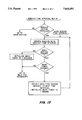
- FIG. 7 is a schematic diagram of the mode switch of the invention.
- FIG. 8 is a schematic of the DC input of the invention.
- FIG. 9 are wave form diagrams corresponding to the nodes labeled A-F in FIG. 5.
- FIGS. 10A and 10B is a flow chart diagram showing the way in which the push button selects the various functions, controls the display, and switches operating modes of the engine monitor.
- FIGS. 11-17 are flow chart diagrams showing the manner in which the software running on micro-controller 50 controls the operation of the engine monitor wherein FIGS. 12A and 12B are flow charts showing the relationship of the timer display and associated functions and FIGS. 14A, 14B and 14C are flow charts showing the monitoring of RPM data in relationship to timer modes.
- FIG. 1 shows an engine monitor 10 in accordance with this invention installed on a portable air compressor 12.
- the compressor is powered by a conventional internal combustion engine 14 having a spark plug 16 disposed in a cylinder 18 for driving the compressor.
- the spark plug 16 is connected to a conventional spark coil or magneto, not shown, by a spark plug wire 20 leading to a removable cap 22 that engages the spark plug 16.
- the engine monitor 10, shown in an enlarged view at FIG. 2, is mechanically attached to the compressor by conventional fasteners 24, 26 such as bolts, extending through two mounting lugs 30, 32 integrally formed with the case of the engine monitor 10.
- a spark plug pick up wire, or antenna wire 36 has one end having several turns 38 wrapped around the spark plug wire 20 and another end mechanically fastened to a clamp 40 on the outside of the engine monitor case and inductively and capacitively coupled to a spark pick up terminal within the case.
- the pick up wire 36 may be secured to the spark plug wire in any conventional fashion such as through the use of tape or a clamp or the like.
- the spark pick up wire 36 is preferably secured to the spark plug wire 20 with a tamper evident attachment.
- FIGS. 3 and 4 show the manner in which the spark pick-up wire 36 is inductively and capacitively coupled to the circuit of the engine monitor.
- the engine monitor includes a clamp for securing an end of the spark plug pick-up wire adjacent to a tab 42 electrically connected to a trace on a printed circuit wiring board 46 disposed within the housing of the engine monitor of this invention.
- the circuitry of the engine monitor will be described in more detail below.
- the clamp 40 forms the end of the wire into an inverted U-shape as shown in FIG. 4.
- FIG. 5 is a schematic diagram showing the overall arrangement of an engine monitor in accordance with this invention
- FIGS. 6-8 show components for implementing the optional job guard, mode switch, and non-spark engine functions of the engine monitor.
- the engine monitor 10 includes a conventional general purpose microcomputer such as a MC 68HC05L5 microcomputer manufactured by Motorola.
- the microcomputer includes read only memory for storing the computer software program that controls the operation of the monitor, read/write memory for use in executing the program, and for storing temporary values, such as the job time, service time, maximum RPM and the like, as will be described in more detail later, a central processing unit, an LCD display driver, and conventional ancillary circuits, such as a clock for providing timing signals to the microprocessor, and for implementing the total time, job time, and service time functions of the engine monitor.
- a conventional general purpose microcomputer such as a MC 68HC05L5 microcomputer manufactured by Motorola.
- the microcomputer includes read only memory for storing the computer software program that controls the operation of the monitor, read/write memory for use in executing the program, and for storing temporary values, such as the job time, service time, maximum RPM and the like, as will be described in more detail later, a central processing unit,
- the micro controller 50 has a plurality of input and output terminals, including a multi conductor connection 52 to a four and one-half digit LCD display 54, oscillator terminals for connection to a frequency determining component, such as a quartz crystal 56, a plurality of I/O terminals, a reset terminal, an interrupt terminal, all of which, together with others, will be described in more detail below.
- the engine monitor of this invention no direct connection to the spark plug wire of the engine on which the monitor is installed is required.
- the electrical components of the engine monitor are attached to a printed circuit wiring board 46, which is encapsulated in epoxy or the like to both physically secure the components to the board to improve reliability in the sometimes hostile environments in which the engine monitor may operate, and to seal the components and protect them from the environment.
- the engine monitor is preferably enclosed within a plastic case 60, more preferably a case without any through wires or holes, so that the engine monitor as a whole is at least water resistant.
- the engine monitor 10 receives input signals from the spark plug pick up wire 36 inductively and capacitively through the plastic case 60.
- a metal tab 42 which may be about one-quarter inch square is physically positioned adjacent to an unshielded portion of the inside wall of the case in close proximity to a pick up wire clamp 40 attached to the outside of the case.
- the end of the spark plug pick up wire 36 is formed into a small loop 48 arranged parallel to the tab 42 for inductively and capacitively coupling a signal derived from the spark plug wire 36 to the tab 42 for processing within the engine monitor 10.
- the tab 42 within the engine monitor is connected to a rectifier including two diodes 61, 62 for rectifying the spark signal received by the tab 42 and applying it to the base 64 of a transistor 66 connected in a common collector amplifier configuration.
- the output of this amplifier is connected to the base 70 of a second transistor 72 arranged as a pulse differentiator.
- the transistor 72 has a capacitor 74 connected between its collector 76 and emitter 78, and a resistor 80 connected from the collector to a positive voltage supply such as a 3 v battery 82.
- the output of the differentiator is connected to an OR-gate 86 that functions to remove the effects of ringing to produce a clean pulse for each spark.
- the clean output of the OR-gate 86 is connected to a NAND-gate 88 arranged as an inverter having its output 90 connected to a capacitor 92 for differentiating the pulse.
- the differentiated pulse is connected to a second input 94 of the OR-gate.
- the shaped output of the OR-gate 86 is connected to a NAND-gate 96 arranged as an inverter for providing one negative going pulse per spark to an interrupt input 100 of the micro controller 50.
- FIGS. 9A-9F show the wave forms appearing at the like labeled points A-F in FIG. 5.
- the pulse as applied to the interrupt input 100 of the micro controller allows the controller 50 to determine the RPM of the engine to which the monitor is attached, and also to control the total running time, job time, and service lime clocks, by enabling the clocks when the engine is running as shown by the presence of pulses at the interrupt input.
- FIG. 7 which corresponds to Box 7 of FIG. 5, shows the components that are optionally provided for implementing the mode switch function of the invention.
- a single pole single throw momentary contact normally open switch 104 has one terminal 106 connected to a power supply V DD , its other terminal 108 connected to an input terminal 110 of the micro controller 50, and a high value resistor 112 connected to the negative battery terminal V SS of the engine monitor.
- the mode switch provides a signal that can be sampled by the micro controller on a regular basis to determine when the switch is pressed. When the engine monitor is provided in a run time only mode, without any other functions, the switch 104 may be omitted.
- FIG. 6 and Box 6 show the components for implementing the job time reset function of the invention, as will be described in more detail later.
- the job time reset functional allows an external controller that includes an electro-magnetic oscillator, for example, to be brought into proximity with the engine monitor for resetting the job time.
- a tuned circuit including an inductor 120 and a capacitor 122 is responsive to a signal produced by the electromagnetic oscillator.
- a detector including a diode 124 and a capacitor 126 are connected to the circuit and a zener diode 128 limits the voltage produced by the circuit before applying it to an input 130 of the micro controller. In this way a signal is produced when the external oscillator is brought into close proximity with the engine monitor.
- a pull down resistor 132 keeps input 130 low unless a reset signal is present.
- Mother optional function is to provide a running time indication whenever a DC voltage is applied to the engine monitor. This is useful in non-spark plug engines such as diesel engines.
- the components for implementing this function are shown in FIG. 8, which corresponds to Box 8 of FIG. 3.
- a conventional opto-coupler 140 is connected to a pair of input terminals 142, 144 through a diode 146 and a resistor 148 for protecting against an inadvertent reverse polarity connection and limiting the current through the opto-coupler.
- the output 150 of the opto-coupler is connected to an input 152 of the micro controller 50 where its signal is sensed by software in a manner analogous to the signal produced by the spark plug conditioning circuit to indicate that the engine is running.
- a pull down resistor 154 keeps output 150 low except when a DC signal is applied to terminal 142, 144.
- the flow chart in FIG. 10 shows all of the available functions of the engine monitor.
- the engine monitor may be supplied to a user with all functions enabled, or with only a sub-set of functions enabled.
- the functions, total time 200, RPM 300, job time 400, service time 500, and service set 600 are shown.
- the engine monitor itself continuously loops through these functions without the need for user intervention.
- the user can select which function is displayed and configure the engine monitor modes within each function.
- the total time mode 200 has no user configurable options.
- the total time is initialized to zero 210 during the manufacture of the engine monitor, and is operable continuously whenever the engine monitor is connected to an engine that is running. As will be described in more detail below, the total time accumulates whenever either a signal from the spark sensor is detected by the engine monitor, or a DC signal indicating that power is being provided to a non-spark engine is sensed.
- total time function may include an error code display function that is designed not to be inadvertently accessed by the user. If the button 160 is pressed and held for more than 10 seconds, the display of the engine monitor shows a code indicating either normal operation or one or more preselected error conditions. This allows malfunctions of the engine monitor to be diagnosed either when the monitor is returned to the factory, or in an appropriate circumstance remotely by instructing a user as to entering the error mode.
- the user switches between the main modes: total time, RPM, job time, service time and service set by pressing and releasing the button in less than three seconds. Repeated short button pushes therefore cycle through the main modes.
- a plurality of sub-modes are selected from the main mode by pressing and holding the button for periods greater than 3 seconds, as will now be described in more detail.
- the RPM code is displayed in the minutes position for three seconds 302.
- the RPM code indicates the ratio of sparks to RPM currently selected.
- Three RPM modes are provided, P1 in which one spark equals one RPM, P2 in which 2 sparks equal 1 RPM, and P3 in which one spark equals 2 RPM.
- the RPM mode can be selected manually by the user or can be permanently configured by internal jumpers, as will be described later.
- the display shows the current RPM of the engine in the four and one-half digit hours portion of the display.
- the engine monitor includes a memory in the micro controller for storing the maximum RPM detected by the monitor since the maximum RPM function was reset.
- the maximum RPM display mode is selected from the RPM mode by pressing and holding the button for more than three seconds.
- the display shows the maximum RPM up to 19,999 in the hours position of the display and displays the letters HI in the minutes position for up to 6 seconds. If the button is released while the maximum RPM is displayed, the monitor reverts to the RPM mode. button is released while the maximum RPM is displayed, the monitor reverts to the RPM mode.
- the maximum RPM reset mode 308 is entered if enabled by the presence of an internal jumper R9. If the jumper is present, the memory storing the maximum RPM is erased, and the display is set to 0000. If the button is released from this mode, the monitor reverts to the RPM mode 300. If the maximum RPM reset mode 308 is not enabled or if the button is held more than three seconds after the maximum RPM has been reset, the monitor enters the tachometer set mode 310. When this mode is first entered, the display shows the current tachometer mode in the least hours position.
- the display shifts to the next tachometer mode, 314 and after one more second to the third mode 316. As long as the button is held, the unit cycles among the three tachometer modes continuously.
- the user selects the desired mode by releasing the button while the unit is in the desired mode and the display shows the code for the desired mode.
- the maximum RPM is recalculated 320 if it has not been erased. Preferably the maximum RPM is not displayed at the time of recalculation, but stored directly in memory for display in the maximum RPM mode as already described. Once a new tachometer mode is selected or the current mode is left undisturbed, operation reverts to the normal RPM mode.
- the job time mode 400 is entered.
- the job time mode displays elapsed ruing time since the last time the job time was reset. Two options are available for resetting job time. If a job guard jumper is enabled at the factory, a job guard signal must be provided to reset the job time. If the engine monitor is not configured in a job guard configuration, the user may reset the job time by button presses alone.
- the monitor When in the job time mode, if the button is held for more than three seconds, the monitor senses whether the job guard jumper 410 is installed. If not, the job time is set to 0 430. When the button is released the monitor reverts to the job time mode. If a jumper is installed to configure the monitor in a job guard configuration, when the button is held for more than three seconds the monitor determines whether a job guard input is present 420 If it is, the job time is reset 430 to 0, as in the mode just discussed. If no job guard input is present, the monitor simply reverts to the job time mode 400 and job time continues to accumulate as long as the engine is running.
- the service time mode 500 is entered by pressing and releasing the button within three seconds.
- the service time mode is provided to enable the monitor to remind a user of the need for periodic service, based on running time of the engine.
- the service time mode timer is reset from the service time mode by holding the button for more than three seconds. After three seconds, the service time display is zeroed 520, and when the button is released, the monitor reverts to the service time mode.
- the user may set the service time interval in the service set mode 600.
- the user enters the service set mode by pressing and releasing the button within three seconds.
- the display shows "OFF"
- the service time mode is simply another timer with no alarm function.
- the service timer accumulates time while the engine is running in substantially the same way as the job time timer.
- the service alarm is enabled when the time accumulated in the service timer exceeds the preselected service interval, a service alarm is activated. This alarm is indicated by flashing the display, preferably at a one half second on, one haft second off rate in all modes of operation, the Total time mode, the RPM mode, The Service Time mode, and the Service Set mode.
- the display shows the current service time interval or "OFF".
- the service time interval is set from the service set mode by pressing and holding the button for more than three seconds. While the button is pressed, the service interval is incremented, preferably each second, in preselected increments. Preferably, the service interval is incremented in five hour steps from five to fifty hours, and then in fifty hour steps from fifty to two hundred and fifty hours, and then back to "OFF".
- the service interval is selected by releasing the button when the desired interval is displayed. In this way, the service interval can be selected as desired by the user or turned “OFF”.
- the selected interval is displayed 630 and the monitor reverts to the service set mode. The monitor can be returned to the total time mode by pressing and releasing the button in less than three seconds. Alternatively, the user can change the service time interval by pressing and holding the button for more than three seconds, and proceeding as just described.
- FIGS. 11-17 are flow charts showing the operation of the software running in microprocessor 50.
- the software is interrupt driven. Each time an interrupt occurs, as shown in FIG. 11, the source of the interrupt is determined and the program flow is directed accordingly.
- the internal clock generates an interrupt every half second, and upon receiving that interrupt flow is directed to the timer routine as shown in FIG. 12.
- a spark signal applied to interrupt pin 100 as shown on FIG. 5 sets the active flag, which starts the total time clock and other clocks as will be described later, and increments the RPM count.
- Releasing the mode button checks the data type change inhibited flag. If data type change was inhibited, it is enabled. If data type change is not inhibited, the display advances to the next data type. A switch directs flow to the selected main function, i.e., total time set-up, RPM set-up, job time set-up, service time set-up or service time interval set-up.
- FIG. 12 shows the timer routine. On entry, if the active flag is set (see FIG. 11), the software blinks the colon to show that the clock is running. If the service time is exceeded, the software flashes the display. If one second has expired, the routine determines whether a minute has passed, and if so, the total time, job time, and service time registers are incremented by a minute. If one and one-half seconds have elapsed, the software determines whether the RPM has been counted. If not, the active flag is cleared to turn off the timers. If the RPM has been counted, the cuttent RPM count is saved to the RPM display buffer, the maximum RPM register is updated as necessary, and the current RPM counter is reset to 0. The software then branches to update the currently active display, that is the total, RPM, job, service, or service time interval displays.
- FIG. 13 shows the total time set-up routine. There are two entry points, total time set-up and show total coming from FIGS. 11 and 12 respectively. If the time option is not installed, that is if the meter is an RPM only meter, control branches to the mode button entry point, as discussed in FIG. 11. Otherwise, the display is updated from the total time buffer.
- the mode button is then detected. If the mode button is not pushed, the mode timer is initialized to 9 seconds, and flow returns to the wait for interrupt routine. If the mode button is pushed, the mode timer is checked and if it has expired, data type change is inhibited and the display is updated with reset information. Flow then returns to the wait for interrupt routine.
- the RPM routine has two entry points, as shown in FIG. 14A. From the set-up entry point, a P-timer is set to three seconds. The monitor determines whether the RPM option is installed. If not, control returns to the mode button routine. If the RPM option is installed, the RPM data register is initialized to the current RPM and control is switched to display the selected one of the current, maximum, zero maximum, or RPM ratio.
- the display is updated from the current RPM buffer.
- the tachometer mode is then set. If the P-timer has not expired, the ratio (mode) is displayed. If the P-timer has expired, the mode button is sensed. If the mode button is not pushed, the mode timer is initialized to 3 seconds. If the mode button is pushed, the mode timer is checked and if it has not expired, control returns to wait for interrupt. If the mode timer has expired, that is if the mode button has been pushed for more than 3 seconds, the which RPM data to display switch is changed to maximum RPM, and data type change is inhibited. The display is updated from the maximum RPM buffer, and the mode timer is initialized to 6 seconds. Flow returns to wait for interrupt.
- the mode timer is sensed. If the mode timer has not expired, the flow reverts to wait for interrupt. If the mode timer has expired, the 0 maximum RPM jumper is sensed. If the zero maximum function is enabled, the RPM data register is zeroed, the display is updated with zeros, the maximim RPM buffer is set to 0, and the mode timer is initialized to 3 seconds. Flow then returns to wait for interrupt.
- the RPM data switch is changed to RPM ratio, and the display is updated with the RPM ratio. Flow then returns to wait for interrupt. What we refer to here as the RPM ratio is the same as the tachometer mode discussed in connection with FIG. 10.
- the mode timer is checked. If the mode timer has not expired, control reverts to wait for interrupt. If the mode timer has ,expired, then again the RPM data is changed to RPM ratio and the display is updated with the new ratio and flow returns to wait for interrupt.
- the change ratio jumper is sensed. If change ratio is enabled, the next RPM ratio is selected and the display is updated with the new ratio. If the ratio change jumper is not enabled, the display is updated but with the same ratio and in either case flow returns to wait for interrupt.
- the job time set-up routine appears in FIG. 15.
- the routine has two entry points, job time set-up and show job time. From job time set-up, the job time option jumper is checked and if the job time option is not enabled, flow returns to the mode button routine. If the job option is installed, the display is updated from the job time buffer, and the mode button is sensed. If the mode button is not pushed, the mode timer is initialized to 3 seconds, and flow returns to wait for interrupt. If the mode button is pushed, the mode timer is checked. If it has not expired, flow returns to wait for interrupt. If it has expired, then 3 seconds has passed, data type change is inhibited, and the okay to zero job time terminal is sensed. If enabled, either directly or because an external signal for zeroing job time is present, the job timer is reset to 0, the display is updated, and if the mode button is no longer pressed, the mode timer is initialized to 3 seconds and flow returns to wait for interrupt.
- the service time set-up routine shown in FIG. 16 has 2 entry points. From service time set-up, the service time option jumper is sensed. If it is not present, flow returns to the mode button routine. If the service time option is installed, the display is updated from the service time buffer, and the mode button is sensed. If the mode button is not pushed, the mode timer is initialized to 3 seconds, and flow returns to wait for interrupt. If the mode button is pushed, the mode timer is checked and if the mode timer has expired, that is if more than 3 seconds has elapsed, data type change is inhibited, and the service time is reset to 0. The display is updated and assuming the mode button is no longer pushed, the mode timer is reinitialized to 3 seconds and control reverts to the wait for interrupt routine.
- the service time interval set-up routine appears on page 17. This routine has two entry points, the set-up entry point and the show service time interval entry point. From the set-up entry point, the service option jumper is checked, and if the service option is not installed, flow returns to the mode button routine. If the service option is installed, the display is updated with the current service time interval. If the mode button is not pushed, the mode timer is initialized to 3 seconds, and flow returns to the wait for interrupt routine. If the mode button is pushed, the mode timer is checked, and if it has expired, indicating that the mode button has been pushed for more than 3 seconds, data type change is inhibited and the service time interval is advanced to the next interval.
- the mode timer is then initialized to 1 second, and the display is updated with the new service time interval. If the mode button is still pushed, and the mode timer has expired, that is if one second has passed, the time interval is advanced again, the mode timer is reset, and this cycle continues as long as the mode button is still pushed, allowing the service time interval to be cycled through its complete range. Once the mode button is released, the mode timer is initialized to 3 seconds, and flow returns to the wait for interrupt routine.
Abstract
Description
Claims (28)
Priority Applications (1)
| Application Number | Priority Date | Filing Date | Title |
|---|---|---|---|
| US08/189,321 US5644491A (en) | 1994-01-31 | 1994-01-31 | Self contained multi-function engine monitor and timer for providing engine running time, job time, service time and tachometer functions |
Applications Claiming Priority (1)
| Application Number | Priority Date | Filing Date | Title |
|---|---|---|---|
| US08/189,321 US5644491A (en) | 1994-01-31 | 1994-01-31 | Self contained multi-function engine monitor and timer for providing engine running time, job time, service time and tachometer functions |
Publications (1)
| Publication Number | Publication Date |
|---|---|
| US5644491A true US5644491A (en) | 1997-07-01 |
Family
ID=22696817
Family Applications (1)
| Application Number | Title | Priority Date | Filing Date |
|---|---|---|---|
| US08/189,321 Expired - Lifetime US5644491A (en) | 1994-01-31 | 1994-01-31 | Self contained multi-function engine monitor and timer for providing engine running time, job time, service time and tachometer functions |
Country Status (1)
| Country | Link |
|---|---|
| US (1) | US5644491A (en) |
Cited By (23)
| Publication number | Priority date | Publication date | Assignee | Title |
|---|---|---|---|---|
| US5968108A (en) * | 1997-07-18 | 1999-10-19 | Honda Giken Kogyo Kabushiki Kaisha | Vehicle diagnosing apparatus |
| US6205395B1 (en) | 1997-10-31 | 2001-03-20 | Holley Performance Products, Inc. | Ignition system and method of programming an ignition system |
| US6259998B1 (en) * | 1998-02-16 | 2001-07-10 | Paul D. Crunk | Adaptable engine tachometer device |
| US6272428B1 (en) | 1997-10-31 | 2001-08-07 | Holley Performance Products, Inc. | Method and system for engine ignition for timing controlled on a per cylinder basis |
| US6339743B1 (en) | 1997-10-31 | 2002-01-15 | Holley Performance Products, Inc. | Ignition system and method of programming an ignition system |
| WO2002019042A2 (en) * | 2000-08-30 | 2002-03-07 | Briggs & Stratton Corporation | Monitoring system for an internal combustion engine |
| US6377168B1 (en) | 2000-09-07 | 2002-04-23 | Delta Systems, Inc. | Engine operation detecting circuit for a visual display |
| US6609357B1 (en) | 2002-01-31 | 2003-08-26 | Delta Systems, Inc. | Lawn and garden control module |
| US6687552B1 (en) * | 1999-03-30 | 2004-02-03 | Oxley Developments Company Limited | Data indicator |
| US20040164857A1 (en) * | 2003-02-24 | 2004-08-26 | Delta Systems, Inc. | Hour meter with incremental service indicator |
| US20050053447A1 (en) * | 2003-09-09 | 2005-03-10 | Ariens Company | Data collection apparatus and method |
| US20050249042A1 (en) * | 2004-05-10 | 2005-11-10 | Delta Systems, Inc. | Digital engine hour meter for outdoor power equipment |
| US20070104034A1 (en) * | 2005-11-08 | 2007-05-10 | Powermate Corporation | LCD Panel Meter for a Generator |
| US20070297291A1 (en) * | 2005-11-08 | 2007-12-27 | Powermate Corporation | Maintenance panel for a generator |
| EP2034453A2 (en) | 2007-09-07 | 2009-03-11 | Deere & Company | Tamper resistant hourmeter for mower |
| US20090095062A1 (en) * | 2007-10-09 | 2009-04-16 | Gary Warren | Spark plug sensor probe utilizing PCB as antenna |
| US20090274263A1 (en) * | 2008-05-05 | 2009-11-05 | Collins Michael P | Run-Time Meter With Blind Interface |
| GB2463059A (en) * | 2008-09-01 | 2010-03-03 | Simon Victor De Banke | Inductively coupled engine speed monitor |
| US8653365B1 (en) * | 2009-01-23 | 2014-02-18 | Claude W. Mixon | Overfill warning wiring system for tank trucks |
| US9002585B2 (en) | 2013-08-29 | 2015-04-07 | Exmark Manufacturing Company, Incorporated | Control system for grounds maintenance vehicle, and grounds maintenance vehicle including same |
| US9462746B1 (en) * | 2006-03-10 | 2016-10-11 | The Toro Company | Outdoor power equipment unit having encapsulated, housing free electronic controller |
| WO2019006163A1 (en) * | 2017-06-29 | 2019-01-03 | Briggs & Stratton Corporation | Engine operation detection system |
| US10701859B2 (en) | 2016-01-07 | 2020-07-07 | Exmark Manufacturing Company, Incorporated | Electronic controller and turf maintenance vehicle incorporating same |
Citations (40)
| Publication number | Priority date | Publication date | Assignee | Title |
|---|---|---|---|---|
| US3886450A (en) * | 1973-08-06 | 1975-05-27 | Sun Electric Corp | Wireless portable tachometer |
| US3965669A (en) * | 1975-02-18 | 1976-06-29 | Eaton Corporation | Engine running time indicator |
| USRE28904E (en) * | 1971-11-22 | 1976-07-13 | Scans Associates, Inc. | Method and apparatus for testing internal combustion engines |
| US4135246A (en) * | 1976-12-13 | 1979-01-16 | General Electric Company | Integrated history recorder for gas turbine engines |
| US4192179A (en) * | 1978-10-06 | 1980-03-11 | Edward Yelke | Piezoelectric transducer for fuel injection engine |
| US4207611A (en) * | 1978-12-18 | 1980-06-10 | Ford Motor Company | Apparatus and method for calibrated testing of a vehicle electrical system |
| US4296409A (en) * | 1979-03-12 | 1981-10-20 | Dickey-John Corporation | Combine performance monitor |
| US4304126A (en) * | 1978-10-06 | 1981-12-08 | Edward Yelke | Transducer for fuel injection engine with flexible piezoelectric element |
| US4319481A (en) * | 1979-12-03 | 1982-03-16 | Edward Yelke | Clip-on piezoelectric transducer |
| US4404641A (en) * | 1981-02-17 | 1983-09-13 | Dierckx Equipment Corporation | Maintenance monitor |
| US4437538A (en) * | 1982-03-30 | 1984-03-20 | Ingemar Ohlsson | Ear-cap |
| US4551803A (en) * | 1981-07-17 | 1985-11-05 | Nissan Motor Company, Limited | Electronic engine control system for controlling the energy conversion process of an internal combustion engine |
| US4559637A (en) * | 1983-09-12 | 1985-12-17 | Weber Harold J | Tamper proof digital value accumulator and display method and apparatus |
| US4575809A (en) * | 1980-06-20 | 1986-03-11 | Rca Corporation | Digital timing method for spark advance |
| US4578755A (en) * | 1982-11-12 | 1986-03-25 | Snap-On Tools Corporation | Microprocessor controlled timing/tachometer apparatus |
| US4644284A (en) * | 1984-12-26 | 1987-02-17 | Friedline James G | Distributorless ignition system interface for engine diagnostic testers |
| US4677847A (en) * | 1985-09-30 | 1987-07-07 | Aisin Seiki Kabushiki Kaisha | Automotive engine oil monitoring system |
| US4812768A (en) * | 1985-08-23 | 1989-03-14 | Snap-On Tools Corporation | Digital engine analyzer |
| US4812979A (en) * | 1985-02-16 | 1989-03-14 | Horst Hermann Company | Method and apparatus for analyzing the performance of the electronic ignition of an internal combustion engine |
| US4821216A (en) * | 1987-04-10 | 1989-04-11 | Howell Instruments, Inc. | Multifunction meter for use in an aircraft |
| US4831536A (en) * | 1985-12-20 | 1989-05-16 | Honda Giken Kogyo Kabushiki Kaisha | Method of processing controlled variables in engine control system |
| US4831560A (en) * | 1986-01-15 | 1989-05-16 | Zaleski James V | Method for testing auto electronics systems |
| US4853859A (en) * | 1985-01-24 | 1989-08-01 | Shin Caterpillar Mitsubishi Ltd. | Operation data recording system |
| US4975846A (en) * | 1987-10-09 | 1990-12-04 | Fuji Jukogyo Kabushiki Kaisha | Diagnosis system for a motor vehicle |
| US5001431A (en) * | 1990-02-02 | 1991-03-19 | Bear Automotive Service Equipment Company | Clip for holding ignition wires of different sizes |
| US5003478A (en) * | 1988-02-16 | 1991-03-26 | Fuji Jukogyo Kabushiki Kaisha | Diagnosis system for a motor vehicle |
| US5004984A (en) * | 1989-09-08 | 1991-04-02 | Snap-On Tools Corporation | Magnetic field pickup assembly for diagnositics on specific engine |
| US5043659A (en) * | 1989-12-18 | 1991-08-27 | Clean Air Technologies Inc. | Non-intrusive tachometer for spark ignition autos |
| US5050080A (en) * | 1988-09-28 | 1991-09-17 | Fuji Jukogyo Kabushiki Kaisha | Diagnostic system for a motor vehicle |
| US5151654A (en) * | 1988-07-06 | 1992-09-29 | Systems Control, Inc. | Tachometer system for measuring the RPM of an internal combustion engine with no physical or visual connection |
| US5160892A (en) * | 1990-10-05 | 1992-11-03 | Bear Automotive Service Equipment Company | Engine analyzer waveform display with a buffer region |
| US5198980A (en) * | 1990-11-05 | 1993-03-30 | Patrick James D | Portable testing apparatus for airplane engines |
| US5208541A (en) * | 1991-06-19 | 1993-05-04 | Daniel Yerkovich | Spark plug firing sensor with capacitive coupling and optical pickup |
| US5214582A (en) * | 1991-01-30 | 1993-05-25 | Edge Diagnostic Systems | Interactive diagnostic system for an automotive vehicle, and method |
| US5222469A (en) * | 1992-06-09 | 1993-06-29 | Thermo King Corporation | Apparatus for monitoring an internal combustion engine of a vehicle |
| US5257190A (en) * | 1991-08-12 | 1993-10-26 | Crane Harold E | Interactive dynamic realtime management system for powered vehicles |
| US5307017A (en) * | 1991-11-28 | 1994-04-26 | Honda Giken Kogyo Kabushiki Kaisha | Sparking voltage detecting device for internal combustion engines |
| US5317267A (en) * | 1991-04-12 | 1994-05-31 | Ngk Spark Plug Co., Ltd. | Spark plug voltage probe for use with an internal combustion engine |
| US5337003A (en) * | 1992-12-28 | 1994-08-09 | Carmichael Edward W | Self-contained, clip-on engine operating time log |
| US5397860A (en) * | 1993-10-29 | 1995-03-14 | Splitfire, Inc. | Multiple-core electrical ignition system cable |
-
1994
- 1994-01-31 US US08/189,321 patent/US5644491A/en not_active Expired - Lifetime
Patent Citations (41)
| Publication number | Priority date | Publication date | Assignee | Title |
|---|---|---|---|---|
| USRE28904E (en) * | 1971-11-22 | 1976-07-13 | Scans Associates, Inc. | Method and apparatus for testing internal combustion engines |
| US3886450A (en) * | 1973-08-06 | 1975-05-27 | Sun Electric Corp | Wireless portable tachometer |
| US3965669A (en) * | 1975-02-18 | 1976-06-29 | Eaton Corporation | Engine running time indicator |
| US4135246A (en) * | 1976-12-13 | 1979-01-16 | General Electric Company | Integrated history recorder for gas turbine engines |
| US4192179A (en) * | 1978-10-06 | 1980-03-11 | Edward Yelke | Piezoelectric transducer for fuel injection engine |
| US4304126A (en) * | 1978-10-06 | 1981-12-08 | Edward Yelke | Transducer for fuel injection engine with flexible piezoelectric element |
| US4207611A (en) * | 1978-12-18 | 1980-06-10 | Ford Motor Company | Apparatus and method for calibrated testing of a vehicle electrical system |
| US4296409A (en) * | 1979-03-12 | 1981-10-20 | Dickey-John Corporation | Combine performance monitor |
| US4319481A (en) * | 1979-12-03 | 1982-03-16 | Edward Yelke | Clip-on piezoelectric transducer |
| US4575809A (en) * | 1980-06-20 | 1986-03-11 | Rca Corporation | Digital timing method for spark advance |
| US4404641A (en) * | 1981-02-17 | 1983-09-13 | Dierckx Equipment Corporation | Maintenance monitor |
| US4551803A (en) * | 1981-07-17 | 1985-11-05 | Nissan Motor Company, Limited | Electronic engine control system for controlling the energy conversion process of an internal combustion engine |
| US4437538A (en) * | 1982-03-30 | 1984-03-20 | Ingemar Ohlsson | Ear-cap |
| US4578755A (en) * | 1982-11-12 | 1986-03-25 | Snap-On Tools Corporation | Microprocessor controlled timing/tachometer apparatus |
| US4559637A (en) * | 1983-09-12 | 1985-12-17 | Weber Harold J | Tamper proof digital value accumulator and display method and apparatus |
| US4644284A (en) * | 1984-12-26 | 1987-02-17 | Friedline James G | Distributorless ignition system interface for engine diagnostic testers |
| US4853859A (en) * | 1985-01-24 | 1989-08-01 | Shin Caterpillar Mitsubishi Ltd. | Operation data recording system |
| US4812979A (en) * | 1985-02-16 | 1989-03-14 | Horst Hermann Company | Method and apparatus for analyzing the performance of the electronic ignition of an internal combustion engine |
| US4812768A (en) * | 1985-08-23 | 1989-03-14 | Snap-On Tools Corporation | Digital engine analyzer |
| US4677847A (en) * | 1985-09-30 | 1987-07-07 | Aisin Seiki Kabushiki Kaisha | Automotive engine oil monitoring system |
| US4831536A (en) * | 1985-12-20 | 1989-05-16 | Honda Giken Kogyo Kabushiki Kaisha | Method of processing controlled variables in engine control system |
| US4831560A (en) * | 1986-01-15 | 1989-05-16 | Zaleski James V | Method for testing auto electronics systems |
| US4821216A (en) * | 1987-04-10 | 1989-04-11 | Howell Instruments, Inc. | Multifunction meter for use in an aircraft |
| US4975846A (en) * | 1987-10-09 | 1990-12-04 | Fuji Jukogyo Kabushiki Kaisha | Diagnosis system for a motor vehicle |
| US5003478A (en) * | 1988-02-16 | 1991-03-26 | Fuji Jukogyo Kabushiki Kaisha | Diagnosis system for a motor vehicle |
| US5151654A (en) * | 1988-07-06 | 1992-09-29 | Systems Control, Inc. | Tachometer system for measuring the RPM of an internal combustion engine with no physical or visual connection |
| US5050080A (en) * | 1988-09-28 | 1991-09-17 | Fuji Jukogyo Kabushiki Kaisha | Diagnostic system for a motor vehicle |
| US5004984A (en) * | 1989-09-08 | 1991-04-02 | Snap-On Tools Corporation | Magnetic field pickup assembly for diagnositics on specific engine |
| US5043659A (en) * | 1989-12-18 | 1991-08-27 | Clean Air Technologies Inc. | Non-intrusive tachometer for spark ignition autos |
| US5001431A (en) * | 1990-02-02 | 1991-03-19 | Bear Automotive Service Equipment Company | Clip for holding ignition wires of different sizes |
| US5160892A (en) * | 1990-10-05 | 1992-11-03 | Bear Automotive Service Equipment Company | Engine analyzer waveform display with a buffer region |
| US5198980A (en) * | 1990-11-05 | 1993-03-30 | Patrick James D | Portable testing apparatus for airplane engines |
| US5214582A (en) * | 1991-01-30 | 1993-05-25 | Edge Diagnostic Systems | Interactive diagnostic system for an automotive vehicle, and method |
| US5214582C1 (en) * | 1991-01-30 | 2001-06-26 | Edge Diagnostic Systems | Interactive diagnostic system for an automobile vehicle and method |
| US5317267A (en) * | 1991-04-12 | 1994-05-31 | Ngk Spark Plug Co., Ltd. | Spark plug voltage probe for use with an internal combustion engine |
| US5208541A (en) * | 1991-06-19 | 1993-05-04 | Daniel Yerkovich | Spark plug firing sensor with capacitive coupling and optical pickup |
| US5257190A (en) * | 1991-08-12 | 1993-10-26 | Crane Harold E | Interactive dynamic realtime management system for powered vehicles |
| US5307017A (en) * | 1991-11-28 | 1994-04-26 | Honda Giken Kogyo Kabushiki Kaisha | Sparking voltage detecting device for internal combustion engines |
| US5222469A (en) * | 1992-06-09 | 1993-06-29 | Thermo King Corporation | Apparatus for monitoring an internal combustion engine of a vehicle |
| US5337003A (en) * | 1992-12-28 | 1994-08-09 | Carmichael Edward W | Self-contained, clip-on engine operating time log |
| US5397860A (en) * | 1993-10-29 | 1995-03-14 | Splitfire, Inc. | Multiple-core electrical ignition system cable |
Cited By (34)
| Publication number | Priority date | Publication date | Assignee | Title |
|---|---|---|---|---|
| US5968108A (en) * | 1997-07-18 | 1999-10-19 | Honda Giken Kogyo Kabushiki Kaisha | Vehicle diagnosing apparatus |
| US6205395B1 (en) | 1997-10-31 | 2001-03-20 | Holley Performance Products, Inc. | Ignition system and method of programming an ignition system |
| US6272428B1 (en) | 1997-10-31 | 2001-08-07 | Holley Performance Products, Inc. | Method and system for engine ignition for timing controlled on a per cylinder basis |
| US6339743B1 (en) | 1997-10-31 | 2002-01-15 | Holley Performance Products, Inc. | Ignition system and method of programming an ignition system |
| US6259998B1 (en) * | 1998-02-16 | 2001-07-10 | Paul D. Crunk | Adaptable engine tachometer device |
| US6687552B1 (en) * | 1999-03-30 | 2004-02-03 | Oxley Developments Company Limited | Data indicator |
| WO2002019042A2 (en) * | 2000-08-30 | 2002-03-07 | Briggs & Stratton Corporation | Monitoring system for an internal combustion engine |
| WO2002019042A3 (en) * | 2000-08-30 | 2002-08-01 | Briggs & Stratton Corp | Monitoring system for an internal combustion engine |
| US6542074B1 (en) | 2000-08-30 | 2003-04-01 | Briggs & Stratton Corporation | Monitoring system for an internal combustion engine |
| US6377168B1 (en) | 2000-09-07 | 2002-04-23 | Delta Systems, Inc. | Engine operation detecting circuit for a visual display |
| US6609357B1 (en) | 2002-01-31 | 2003-08-26 | Delta Systems, Inc. | Lawn and garden control module |
| US20040164857A1 (en) * | 2003-02-24 | 2004-08-26 | Delta Systems, Inc. | Hour meter with incremental service indicator |
| US7034674B2 (en) | 2003-02-24 | 2006-04-25 | Delta Systems, Inc. | Hour meter with incremental service indicator |
| US20050053447A1 (en) * | 2003-09-09 | 2005-03-10 | Ariens Company | Data collection apparatus and method |
| US7076348B2 (en) | 2003-09-09 | 2006-07-11 | Ariens Company | Data collection apparatus and method |
| US7154814B2 (en) | 2004-05-10 | 2006-12-26 | Delta Systems, Inc. | Digital engine hour meter for outdoor power equipment |
| US20050249042A1 (en) * | 2004-05-10 | 2005-11-10 | Delta Systems, Inc. | Digital engine hour meter for outdoor power equipment |
| US20070104034A1 (en) * | 2005-11-08 | 2007-05-10 | Powermate Corporation | LCD Panel Meter for a Generator |
| US20070297291A1 (en) * | 2005-11-08 | 2007-12-27 | Powermate Corporation | Maintenance panel for a generator |
| US9462746B1 (en) * | 2006-03-10 | 2016-10-11 | The Toro Company | Outdoor power equipment unit having encapsulated, housing free electronic controller |
| US7649810B2 (en) | 2007-09-07 | 2010-01-19 | Deere & Company | Tamper resistant hourmeter for mower |
| EP2034453A2 (en) | 2007-09-07 | 2009-03-11 | Deere & Company | Tamper resistant hourmeter for mower |
| US20090067293A1 (en) * | 2007-09-07 | 2009-03-12 | Anfinson Bryan L | Tamper resistant hourmeter for mower |
| WO2009047619A2 (en) * | 2007-10-09 | 2009-04-16 | Gary Warren | Spark plug sensor probe utilizing pcb as an antenna |
| WO2009047619A3 (en) * | 2007-10-09 | 2011-04-28 | Gary Warren | Spark plug sensor probe utilizing pcb as an antenna |
| US8033166B2 (en) | 2007-10-09 | 2011-10-11 | Flextronics Automotive Inc. | Spark plug sensor probe utilizing PCB as antenna |
| US20090095062A1 (en) * | 2007-10-09 | 2009-04-16 | Gary Warren | Spark plug sensor probe utilizing PCB as antenna |
| US20090274263A1 (en) * | 2008-05-05 | 2009-11-05 | Collins Michael P | Run-Time Meter With Blind Interface |
| GB2463059A (en) * | 2008-09-01 | 2010-03-03 | Simon Victor De Banke | Inductively coupled engine speed monitor |
| US8653365B1 (en) * | 2009-01-23 | 2014-02-18 | Claude W. Mixon | Overfill warning wiring system for tank trucks |
| US9002585B2 (en) | 2013-08-29 | 2015-04-07 | Exmark Manufacturing Company, Incorporated | Control system for grounds maintenance vehicle, and grounds maintenance vehicle including same |
| US10701859B2 (en) | 2016-01-07 | 2020-07-07 | Exmark Manufacturing Company, Incorporated | Electronic controller and turf maintenance vehicle incorporating same |
| WO2019006163A1 (en) * | 2017-06-29 | 2019-01-03 | Briggs & Stratton Corporation | Engine operation detection system |
| US11022085B2 (en) | 2017-06-29 | 2021-06-01 | Briggs & Stratton, Llc | Engine operation detection system |
Similar Documents
| Publication | Publication Date | Title |
|---|---|---|
| US5644491A (en) | Self contained multi-function engine monitor and timer for providing engine running time, job time, service time and tachometer functions | |
| US4277772A (en) | Motor vehicle diagnostic and monitoring system | |
| US4926352A (en) | Diagnostic system for control apparatus of a motor vehicle | |
| US4404641A (en) | Maintenance monitor | |
| US5337003A (en) | Self-contained, clip-on engine operating time log | |
| US7053497B2 (en) | Monitoring system for a generator | |
| US4532594A (en) | Multiple microcomputer system with comonitoring/back-up for an automotive vehicle | |
| AU680475B2 (en) | Loop powered process control transmitter | |
| US5382942A (en) | Engine oil monitoring system having an in-vehicle display of the current status of the oil | |
| US4887080A (en) | Stationary traffic monitoring device | |
| US4348726A (en) | Method of controlling automobile equipment and control apparatus | |
| JP2581571B2 (en) | Battery voltage warning device | |
| US6044315A (en) | Vehicle non-volatile memory system | |
| US5505076A (en) | Vehicle fuel usage tracking device | |
| US6542074B1 (en) | Monitoring system for an internal combustion engine | |
| JP2002525616A (en) | Wien Gand effect energy generator | |
| US4003019A (en) | Parameter display and alarm installation for motor-driven vehicles | |
| US7154814B2 (en) | Digital engine hour meter for outdoor power equipment | |
| US4611193A (en) | Electric display device of a vehicle | |
| EP0466314B1 (en) | Parking time display device | |
| US5003518A (en) | Running time meter for engine | |
| US6377168B1 (en) | Engine operation detecting circuit for a visual display | |
| EP0708418B1 (en) | Time totaling meter for internal combustion engines | |
| EP0708388A2 (en) | Stop watch and clocking system | |
| US5714929A (en) | Microprocessor-controlled speedometer/odometer |
Legal Events
| Date | Code | Title | Description |
|---|---|---|---|
| AS | Assignment |
Owner name: SENDEC CORPORATION, NEW YORK Free format text: ASSIGNMENT OF ASSIGNORS INTEREST;ASSIGNORS:FISKE, KENTON W.;REEHIL, EDWARD G.;LEY, HERBERT F., III;AND OTHERS;REEL/FRAME:006994/0575 Effective date: 19940509 |
|
| STCF | Information on status: patent grant |
Free format text: PATENTED CASE |
|
| FEPP | Fee payment procedure |
Free format text: PAYOR NUMBER ASSIGNED (ORIGINAL EVENT CODE: ASPN); ENTITY STATUS OF PATENT OWNER: SMALL ENTITY |
|
| FPAY | Fee payment |
Year of fee payment: 4 |
|
| FPAY | Fee payment |
Year of fee payment: 8 |
|
| FPAY | Fee payment |
Year of fee payment: 12 |
|
| AS | Assignment |
Owner name: GLOBAL DIGITAL INSTRUMENTS LLC, NEW YORK Free format text: NUNC PRO TUNC ASSIGNMENT;ASSIGNOR:SENDEC CORP;REEL/FRAME:026276/0521 Effective date: 20110513 |