US5644319A - Multi-resonance horizontal-U shaped antenna - Google Patents

Multi-resonance horizontal-U shaped antenna Download PDF

Info

Publication number
US5644319A
US5644319A US08/455,916 US45591695A US5644319A US 5644319 A US5644319 A US 5644319A US 45591695 A US45591695 A US 45591695A US 5644319 A US5644319 A US 5644319A
Authority
US
United States
Prior art keywords
antenna
base plate
horizontal
arms
side plates
Prior art date
Legal status (The legal status is an assumption and is not a legal conclusion. Google has not performed a legal analysis and makes no representation as to the accuracy of the status listed.)
Expired - Lifetime
Application number
US08/455,916
Inventor
Yung Jinn Chen
Hsueh-Jyh Li
Ruey-Beei Wu
Dou-Ken Lee
Current Assignee (The listed assignees may be inaccurate. Google has not performed a legal analysis and makes no representation or warranty as to the accuracy of the list.)
Industrial Technology Research Institute ITRI
Original Assignee
Industrial Technology Research Institute ITRI
Priority date (The priority date is an assumption and is not a legal conclusion. Google has not performed a legal analysis and makes no representation as to the accuracy of the date listed.)
Filing date
Publication date
Application filed by Industrial Technology Research Institute ITRI filed Critical Industrial Technology Research Institute ITRI
Priority to US08/455,916 priority Critical patent/US5644319A/en
Assigned to INDUSTRIAL TECHNOLOGY RESEARCH INSTITUTE reassignment INDUSTRIAL TECHNOLOGY RESEARCH INSTITUTE ASSIGNMENT OF ASSIGNORS INTEREST (SEE DOCUMENT FOR DETAILS). Assignors: CHEN, YUNG JINN, LEE, DOU-KEN, LI, HSUEH-JYH, WU, RUEY-BEEI
Application granted granted Critical
Publication of US5644319A publication Critical patent/US5644319A/en
Anticipated expiration legal-status Critical
Expired - Lifetime legal-status Critical Current

Links

Images

Classifications

    • HELECTRICITY
    • H01ELECTRIC ELEMENTS
    • H01QANTENNAS, i.e. RADIO AERIALS
    • H01Q9/00Electrically-short antennas having dimensions not more than twice the operating wavelength and consisting of conductive active radiating elements
    • H01Q9/04Resonant antennas
    • H01Q9/0407Substantially flat resonant element parallel to ground plane, e.g. patch antenna
    • H01Q9/0421Substantially flat resonant element parallel to ground plane, e.g. patch antenna with a shorting wall or a shorting pin at one end of the element
    • HELECTRICITY
    • H01ELECTRIC ELEMENTS
    • H01QANTENNAS, i.e. RADIO AERIALS
    • H01Q1/00Details of, or arrangements associated with, antennas
    • H01Q1/12Supports; Mounting means
    • H01Q1/22Supports; Mounting means by structural association with other equipment or articles
    • H01Q1/24Supports; Mounting means by structural association with other equipment or articles with receiving set
    • H01Q1/241Supports; Mounting means by structural association with other equipment or articles with receiving set used in mobile communications, e.g. GSM
    • H01Q1/242Supports; Mounting means by structural association with other equipment or articles with receiving set used in mobile communications, e.g. GSM specially adapted for hand-held use
    • H01Q1/243Supports; Mounting means by structural association with other equipment or articles with receiving set used in mobile communications, e.g. GSM specially adapted for hand-held use with built-in antennas

Definitions

  • This invention relates generally to internal antenna for portable communication system. More particularly, this invention relates to new configuration and method for designing and manufacturing a multi-resonance horizontal-U shaped antenna to broaden the bandwidth of an internal antenna for portable communication system.
  • antennas employed by movable communication systems are extendible types including monopole antenna, whip antenna, sleeve antenna or normal mode helical antenna. It is well known fact in the art that the performance characteristics of these antennas are functions of the height of the antenna extended out of the rectangular metal box used to contain the communication system, e.g., a wireless telephone. Due the design considerations of simplicity, convenience of use, serviceability, reliability, and price, the external extendible antennas are increasingly being replaced by internal antennas. The internal antennas not only provides a design configuration to overcome the difficulties and limitations of the external antennas mentioned above, it further enhances the portability of the communication systems since the antennas can be conveniently placed in a pocket.
  • the micro-strip antenna is most frequently being employed because of its low cost, small volume, light weight and easy to form on a flat surface.
  • the microstip antennas however are limited by the narrow bandwidths.
  • many other types of internal antenna are disclosed including the linear inverted-F antenna, planar inverted-F antenna.
  • the linear inverted-F antenna was disclosed in early 1960s while the planar inverted-F antenna is to replace the linear radiation elements with planar elements.
  • An inverted F-antenna can be considered as a quarter-wave microstrip antenna with air dielectric, matched by the RF-input stage by the position of the feed probe.
  • Such feeds tend to restrict the antenna bandwidth defined by standing wave ratio, i.e., VSWR ⁇ 2. Since the bandwidth as defined by the acceptable radiation patterns is usually much larger than the VSWR bandwidth, additional matching network elements can be added to expand the VSWR bandwidth such that it can approximate the radiation bandwidth. However, this expansion is at the cost of decreasing the radiation efficiency of the antenna caused by non-ideal components of the matching network
  • Rasinger et al. disclose a radiation coupled dual-L antenna which includes two narrow plates in the form of letter L on top of metallic shielding case. The narrow plates are arranged in parallel separated by a narrow slot. These two narrow plates are formed with equal length.
  • This radiation-coupled dual-L antenna is intended to enhance the bandwidth of the antenna without requiring added matching network components thus enhanced bandwidth can be achieved without increasing the occupied volumes or consideration of matching network components.
  • This enhanced bandwidth dual-L antenna has recently been published by Rasinger et al. in 1990 in IEEE Journal as attached herein. For ease of reference, please refer to FIG. 1A to 1E for different configurations of the prior art antennas as discussed above.
  • Rasinger et al. also applies a three-dimensional numerical analytical model i.e., an antenna wire-grid model to obtain calculated data of current distributions, 3-D radiation patterns, and input impedance at a fixed frequency.
  • the analytical model enables an antenna designer to overcome the difficulties that experimental investigation of antenna performance is very time consuming as it depends on geometrical parameters and solder-intensive tinkering. Additionally, the measurement of radiation patterns in an anechoic chamber is very complex, expensive, and time consuming.
  • the three dimensional wire-grid models does not provide sufficient accuracy in defining the current distribution for a more complex antenna configuration. Furthermore, extra long computer execution time is required for performing such analyses when greater of number of grids is used.
  • the technique of the 3-D wire-grid model is often not adequate to satisfy the need for modern antenna design.
  • the dual-L antenna as disclosed by Rasinger is able to increase the bandwidth of the antenna without requiring the use of matching network components.
  • the bandwidth enhancement is still very limited compared to the rapidly increased demand to accommodate a great number of users in the portable tele-communication market.
  • the potential improvements on matching impedance for performance improvement is very limited by changing the position of the feed probe.
  • Another object of the present invention is to provide a new antenna configuration and design method by employing a multi-resonance horizontal-U shaped antenna to provide multiple resonant frequencies for performance improvements.
  • Another object of the present invention is to provide a new antenna configuration and design method by employing a novel design method for the multi-resonance horizontal-U shaped antenna of the present invention to improve the design accuracy and flexibility.
  • the present invention discloses a horizontal-U shaped antenna which includes a conductive base plate including two vertically side plates extending upwardly from one edge of the base plate.
  • the antenna further includes two horizontal conductive antenna arms of unequal lengths each connected to a corresponding side plate extending horizontally over the base plate.
  • the two horizontal conductive antenna arms of unequal lengths and the two corresponding side plates connected thereto further are separated by an opening slot.
  • Another advantage of the present invention is that it provides a new antenna configuration and design method by employing a multi-resonance horizontal-U shaped antenna to provide multiple resonant frequencies for performance improvements.
  • Another advantage of the present invention is that it provides a new antenna configuration and design method by employing a novel design method for the multi-resonance horizontal-U shaped antenna of the present invention to improve the design accuracy and flexibility.
  • FIGS. 1A to 1E are perspective views of the configurations of a series of prior art antennas
  • FIGS. 2 is a perspective view of a horizontal-U shaped antenna of the present invention
  • FIGS. 3 is a perspective view of another horizontal-U shaped antenna of the present invention attached to a containing box;
  • FIGS. 4 is a perspective view of a horizontal-U shaped antenna of FIG. 2 which being divided into a plurality of cells for numerical analysis of the present invention
  • FIGS. 5 is a perspective view of a horizontal-U shaped antenna of FIG. 3 which being divided into a plurality of cells for numerical analysis of the present invention
  • FIG. 6 shows the variations of the input conductance and susceptance as function of frequency of the antenna of FIG. 2;
  • FIG. 7 shows the variations of the input conductance and susceptance as function of frequency of the antenna of FIG. 3 without the containing box;
  • FIG. 8 shows the variations of the input conductance and susceptance as function of frequency of the antenna of FIG. 3 with the containing box;
  • FIG. 9 shows the variations of the input conductance and susceptance as function of frequency of the antenna of FIG. 2 with feed probe placed at different positions;
  • FIG. 10 shows the variations of the input conductance and susceptance as function of frequency of the antenna of FIG. 2 with feed probes of different diameters;
  • FIG. 11 shows the variations of the reflection coefficient as function of frequency of the antennas of FIG. 2 and FIG. 3;
  • FIG. 12 shows the variations of the reflection coefficient as function of frequency of the antenna of FIG. 3 with uniform opening slot and tapered opening slot;
  • FIG. 13 shows the variations of the reflection coefficient as function of frequency of another antenna with and without the containing box
  • FIG. 14 shows the current distribution on the surface of the antenna of FIG. 2 at two resonant frequencies
  • FIG. 15 shows the current distribution on the surface of the antenna of FIG. 3 at two resonant frequencies
  • FIG. 16 is a flowchart showing a design procedure for a multiple resonance horizontal U-shaped antenna applying a full wavelength equivalent circuit technique of this invention
  • FIGS. 17a to 17c show the cell elements used in the full wavelength equivalent circuit technique of this invention.
  • FIGS. 18a and 18b shows the surface current in a cell element and the equivalent circuits for the full wavelength equivalent circuit technique of this invention.
  • FIG. 2 shows a new multi-resonance horizontal-U antenna 100 of the present invention before the antenna is attached to a box for containing communication system, e.g., a wireless telephone.
  • the horizontal-U antenna 100 includes a base plate 110 of length L6 and two horizontal antenna arms 115 and 120 with arm lengths of L1 and L2 respectively. Each of these horizontal antenna arms 115 and 120 are connected to the base plate 110 via a side plate 122 and 124 respectively. A set of preferred dimensions of the antenna 100 are shown wherein the lengths L1, L2, and L6 are all of different values.
  • the feedline 125 from the communication system is extended from a via 130 on the base plate 110 to be in contact with the horizontal antenna arm 120.
  • FIG. 3 shows another preferred embodiment of the present invention where a multi-resonance horizontal-U antenna 200 is provided to be attached to a box 250 for containing a communication system therein. Similar to the horizontal-U antenna 100 as shown in FIG. 1, the horizontal-U antenna 200 also includes a base plate 210 and two horizontal antenna arms 215 and 220 which are connected to the base plate 210 via two side plates 222 and 224 respectively. A set of dimensions of a preferred embodiment is shown in FIG. 2 also.
  • the upper cover of the box 250 is composed of plastic material such that minimum interference is caused by the upper cover which is right underneath the base plate 210.
  • Other parts of the containing box 210 are composed of material coated with metallic paints to function as electromagnetic wave, i.e., E-M wave, radiating body.
  • the present invention discloses a horizontal-U shaped antenna 100 which includes a conductive base plate 110 including two vertically side plates 122 and 124 extending upwardly from one edge of the base plate 110.
  • the antenna 100 further includes two horizontal conductive antenna arms 115 and 120 of unequal lengths each connected to a corresponding side plate 122 and 124 respectively, extending horizontally over the base plate 110.
  • the two horizontal conductive antenna arms 115 and 120 of unequal lengths and the two corresponding side plates 122 and 124 connected thereto further are separated by an opening slot,
  • the antenna is now managed as it is formed with a plurality of ⁇ cells ⁇ in a new analytical model i.e., the full wave equivalent circuit model.
  • the cells can be rectangles, triangles, or even a wire.
  • the antennas of the present invention as that shown in FIGS. 2 and 3 can be modeled as FIGS. 4 and 5 respectively.
  • the details of the full wave equivalent circuit model including the electromagnetic equations employed to model the antenna as equivalent circuits are presented in Appendix A.
  • FIG. 6 The calculated and measured input conductance and input susceptance for the multi-resonant horizontal-U antenna 100 is shown in FIG. 6. It is very clear that antenna 100 has two resonant modes. The first resonant mode occurs at 1.87 GHz and the second resonant mode occurs around 2.17 GHz. Similar to FIG. 6, FIGS. 7 and 8 show the input conductance and input susceptance for the antenna 200 without and with the containing box respectively. In examining the data shown in these two figures, it is found that as a result of adding the containing box, the first resonance frequency is changed from 1.605 GHz to 1.7 GHz, and the second resonance frequency is changed from 2.17 to 1.95 GHz. As these two resonance frequencies are drawn closer, the bandwidth is expanded. FIG.
  • FIG. 9 shows the variation of calculated input conductance and input susceptance as function of the feed probe positions, i.e., y f when all other parameters are maintained the same. The relative frequency difference between two resonant frequencies remains substantially unchanged while the two resonant frequencies move higher as y f is increased.
  • FIG. 10 shows the variation of calculated input conductance and input susceptance as function of the diameter of the feed probe. The first resonant frequency moves higher as the diameter of the feed prove is increased while the second resonant frequency does not change.
  • FIG. 11A shows the reflection coefficient for antenna 100 (FIG. 2) where a 20% is achieved around a resonant frequency around 1.9 GHz
  • FIG. 11B shows the reflection coefficient for antenna 200 (FIG. 3) wherein two curves are shown for the reflection coefficient of antenna 200 with and without the containing box respectively and a bandwidth of about 25% is achieved.
  • FIG. 12A and FIG. 12B show the reflection coefficient of the antenna 200 with uniform slot and tapered slot respectively. In FIG. 12A, the reflection coefficient between 1.7 and 1.8 GHz is greater than -10 dB and this section of bandwidth is not useful.
  • FIG. 12B further shows that the containing box tends to lower the resonance frequencies and also improve the bandwidth.
  • design A seven sets of dimensions, i.e., design A, to B5 are employed for designing the antenna for determination of antenna performance characteristics where type A is for antenna along and type B is for antennas designed with a box for containing a cordless phone therein. It is noted that B5 is for a horizontal-U shaped antenna where there is no opening slot between two horizontal upper arms.
  • An example of the reflection coefficient for design B2 is shown in FIG. 13 where a bandwidth greater than 25% is achieved.
  • FIGS. 14A and 14B show the current distributions, at frequencies 1.87 GHz and 2.16 GHz respectively, on the surface of the base plate 110, two horizontal antenna arms 115 and 120, and two side plates 122 and 124 of a type A antenna 100 in FIG. 2.
  • the currents in two horizontal antenna arms 115 and 120 are in opposite directions while at 2.16 GHz they are in the same direction.
  • the first resonance is induced by the currents in the two horizontal antenna arms 115 and 120 wherein L1+L2 is approximately ⁇ /2.
  • L1+L6 is approximately ⁇ /2.
  • 15A and 15B show the current distributions, at frequencies 1.605 GHz and 2.17 GHz respectively, on the surface of the base plate 210, two horizontal antenna arms 215 and 220, and two side plates 222 and 224 of a type B antenna 200 in FIG. 3.
  • the currents in two horizontal antenna arms 215 and 220 are in opposite directions while at 2.17 GHz they are in the same direction.
  • the first resonance is induced by the currents in the two horizontal antenna arms 215 and 220 wherein L1+L2 is approximately ⁇ /2.
  • the second resonance frequency 2.17 GHz the current density on arm 220 is greater than 215 thus the resonance is more related to arm 220 than arm 215.
  • the full wave length analysis technique as outlined above can be employed to simplify the design process and to optimize the design parameters as that shown in a flow chart in FIG. 16.
  • the process begins (step 300) by making a preliminary selection of the lengths of the base plate, the horizontal antenna arms, e.g., L1, L2, and L6, and the position of the feed probe (step 310).
  • a full wavelength equivalent circuit analysis is then performed (step 320) to calculate the performance parameters such as the resonance frequencies, bandwidth, input impedance and radiation pattern.
  • the geometrical parameters of the antenna are then adjusted and further analyses are performed iteratively to optimize the antenna performance depending on the operation requirement specification of the antenna (step 330).
  • An experiment is then carried out to confirm the performance based on the analysis data (step 340). Further adjustments are made to fine tune the design (step 350) before the design process is completed (step 360).
  • a design is then provided with an effective design process by the use of the full wavelength equivalent technique to achieve optimal design of an antenna in a predictable and controllable manner.
  • This invention also discloses a method of generating multiple-resonance modes of operation in a horizontal-U shaped antenna which includes a conductive base plate of length L6 having two vertically side plates extending upwardly from one edge of the base plate and two horizontal conductive antenna arms of unequal lengths L1 and L2 respectively each connected to a corresponding side plate and extending horizontally over the base plate.
  • the method includes a step of adjusting the lengths of the L1, L2 and L6 whereby L1+L2 and L1+L6 are both approximately half of the wavelength ⁇ corresponding to a main resonance frequency.
  • a method of generating multiple-resonance mode of operation in a horizontal-U shaped antenna is also disclosed in this invention which includes thereof: (a) forming a base plate having multiple vertically side plates extending upwardly from one edge of the base plate; (b) forming multiple horizontal conductive antenna arms corresponding to each of the vertical side plates each being of unequal length and being connected to the corresponding side plate and extending horizontally over the base plate; and (c) adjusting the lengths of the base plates and each of the horizontal antenna arms for achieving the multiple-resonance mode of operation.
  • This invention further discloses a method of designing a multiple-resonance horizontal-U shaped antenna which includes a base plate having multiple vertically side plates extending upwardly from one edge of the base plate and multiple horizontal conductive antenna arms corresponding to each of the vertical side plates each being of unequal length and being connected to the corresponding side plate and extending horizontally over the base plate.
  • This method can be computerized such that automated design procedure can be carried out to achieve savings of human efforts.
  • the method includes the steps of: (a) making a preliminary selection of a plurality of geometrical parameters of the antenna, e.g., step 310; (b) performing a full wavelength equivalent circuit analysis with the geometrical parameters for the antenna for obtaining several performance variables, e.g., step 320; (c) comparing the performance variables with a set of targeted performance variables; and (d) adjusting the lengths of the base plates and each of the horizontal antenna arms for achieving an optimal design wherein the performance variables being most approximating to the target performance variables, i.e., step 350.
  • This invention thus discloses a novel design of high frequency hidden hand-held antenna which includes two metal arms above a lower arm of finite ground plane. By properly choosing the lengths of these arms and the separations between them, the bandwidth can be broadened more than 20%. Thus, it is suitable for personal mobile communication applications.
  • a full wave equivalent circuit analytic model is also developed to analyze and optimize the geometrical configuration including the lengths and separations between the arms. Numerical analyses for current distribution on the conductor surface and various antenna characteristics such as input impedance and radiation patterns are computed by the use of the analytical models. Experimental results and numerical computations all confirm that better performance characteristics including broadened antenna bandwidth are achieved by this novel antenna.
  • the current J(r) on the surface of the multi-resonant horizontal-U shaped antenna 100 as that shown in FIG. 4 can be expressed as:
  • the charge density ⁇ (r) may be obtained as:
  • ⁇ s represents a derivative on the surface of the conductive metal.
  • the metal surface is divided Into many cell elements and the current in each cell is then represented as simple functions which approximate the current density.
  • cell elements i.e., a wire cell, a triangle cell, and a rectangular cell.
  • majority of the cells are rectangular cells, while the intersection parts between the base plate and vertical arms are modeled by the use of triangle cells.
  • the feed probe is modeled by the use of wire cells. The following descriptions provide equations for modeling these different types of cells:
  • the length of the line is l and the diameter is d, and the current density can be defined as:
  • Equation A-7 s representing a coordinate along the line and the basis functions
  • s representing a coordinate along the line and the basis functions can be defined as: ##EQU3##
  • the unknowns I1 and I2 in Equation A-7 may be represented as the current outputs.
  • the charge density corresponding to the current density obtained from the basis function can be derived from Equation A-4 as:
  • A is the total area of the wire and the coefficient Q can be defined as: ##EQU5## is the total charge of this wire cell element.
  • the dimension of the rectangle is a by b and the current can be represented as: ##EQU6##
  • the current can be represented as: ##EQU6##
  • the three points defining the triangle are located at r 1 , r 2 and r 3 whereas three sides are ⁇ 1 , ⁇ 2 , and ⁇ 3 .
  • the current inside the triangle can be represented as: ##EQU9##
  • Equation (A-9) represent the total current output from each side ⁇ i of the triangle, and the charge density is:
  • B Pi (r) is a vector basis representing the current on a boundary line ⁇ Pi of a cell element ⁇ p and I Pi representing the total current flow on that boundary line ⁇ Pi of that cell element ⁇ p .
  • Equation A-5 a functional relationship
  • the third term can be simplified by the divergence theorem as: ##EQU12##
  • the basis function for a cell element has the characteristic that n ⁇ B m (r) has a value of zero.
  • the line integration portion can be neglected.
  • the magnetic vector potential A(r) and the electric scalar potential ⁇ (r) in the above equation can be represented as function of J(r) by the use of Equations (A-2) to (A-4).
  • the current function J(r) can be further expressed as function of the basis functions of each cell. ##EQU13## representing an input voltage.
  • Equation A-14 when the frequency is low e -jkR ⁇ 1, where L qi ,pi is a partial inductance between the bases B qj (r) and B pi (r) and C qp represents a partial capacitance between the q-th and p-th cells.
  • the phase retarded term e -jkR can not be neglected where the inductance and the capacitance are all complex numbers and may be termed as the full wavelength inductance and capacitance.
  • FIG. 18b is a diagram showing such an equivalent circuit.
  • Equation A-12 can be defined as: ##EQU16## Which is consistent with the results obtained above.
  • the input voltage, V m should be maintained at a zero value.
  • the impedance with respect to the antenna input is:

Abstract

A novel design of high frequency hidden hand-held antenna which includes two metal arms above a lower arm of finite ground plane. By properly choosing the lengths of these arms and the separations between them, the bandwidth can be broadened more than 20%. Thus, it is suitable for personal mobile communication applications. A full wave equivalent circuit analytic model is also developed to analyze and optimize the geometrical configuration including the lengths and separations between the arms. Numerical analyses for current distribution on the conductor surface and various antenna characteristics such as input impedance and radiation patterns are computed by the use of the analytical models. Experimental results and numerical computations all confirm that better performance characteristics including broadened antenna bandwidth are achieved by this novel antenna.

Description

BACKGROUND OF THE INVENTION
1. Field of the Invention
This invention relates generally to internal antenna for portable communication system. More particularly, this invention relates to new configuration and method for designing and manufacturing a multi-resonance horizontal-U shaped antenna to broaden the bandwidth of an internal antenna for portable communication system.
2. Description of the Prior Art
Conventional techniques for employing conducting plates or strips configured in different shapes as antennas for transmitting and receiving electromagnetic waves of different frequencies are limited by a major difficulty that the bandwidth provided by the antennas for such transmissions are not sufficiently broad. The demand for broader bandwidth is ever increased for portable communication systems as more communication transmissions are rapidly increased and greater crowd of users are causing `traffic jams` in different frequency-bands.
Most of the traditional antennas employed by movable communication systems are extendible types including monopole antenna, whip antenna, sleeve antenna or normal mode helical antenna. It is well known fact in the art that the performance characteristics of these antennas are functions of the height of the antenna extended out of the rectangular metal box used to contain the communication system, e.g., a wireless telephone. Due the design considerations of simplicity, convenience of use, serviceability, reliability, and price, the external extendible antennas are increasingly being replaced by internal antennas. The internal antennas not only provides a design configuration to overcome the difficulties and limitations of the external antennas mentioned above, it further enhances the portability of the communication systems since the antennas can be conveniently placed in a pocket.
Among several types of internal antennas, the micro-strip antenna is most frequently being employed because of its low cost, small volume, light weight and easy to form on a flat surface. The microstip antennas however are limited by the narrow bandwidths. In order to resolve this difficulty, many other types of internal antenna are disclosed including the linear inverted-F antenna, planar inverted-F antenna. The linear inverted-F antenna was disclosed in early 1960s while the planar inverted-F antenna is to replace the linear radiation elements with planar elements. An inverted F-antenna can be considered as a quarter-wave microstrip antenna with air dielectric, matched by the RF-input stage by the position of the feed probe. Such feeds tend to restrict the antenna bandwidth defined by standing wave ratio, i.e., VSWR≦2. Since the bandwidth as defined by the acceptable radiation patterns is usually much larger than the VSWR bandwidth, additional matching network elements can be added to expand the VSWR bandwidth such that it can approximate the radiation bandwidth. However, this expansion is at the cost of decreasing the radiation efficiency of the antenna caused by non-ideal components of the matching network
Rasinger et al. disclose a radiation coupled dual-L antenna which includes two narrow plates in the form of letter L on top of metallic shielding case. The narrow plates are arranged in parallel separated by a narrow slot. These two narrow plates are formed with equal length. This radiation-coupled dual-L antenna is intended to enhance the bandwidth of the antenna without requiring added matching network components thus enhanced bandwidth can be achieved without increasing the occupied volumes or consideration of matching network components. This enhanced bandwidth dual-L antenna has recently been published by Rasinger et al. in 1990 in IEEE Journal as attached herein. For ease of reference, please refer to FIG. 1A to 1E for different configurations of the prior art antennas as discussed above.
Rasinger et al. also applies a three-dimensional numerical analytical model i.e., an antenna wire-grid model to obtain calculated data of current distributions, 3-D radiation patterns, and input impedance at a fixed frequency. The analytical model enables an antenna designer to overcome the difficulties that experimental investigation of antenna performance is very time consuming as it depends on geometrical parameters and solder-intensive tinkering. Additionally, the measurement of radiation patterns in an anechoic chamber is very complex, expensive, and time consuming. The three dimensional wire-grid models, however, does not provide sufficient accuracy in defining the current distribution for a more complex antenna configuration. Furthermore, extra long computer execution time is required for performing such analyses when greater of number of grids is used. The technique of the 3-D wire-grid model is often not adequate to satisfy the need for modern antenna design.
Even that the dual-L antenna as disclosed by Rasinger is able to increase the bandwidth of the antenna without requiring the use of matching network components. However, since this dual-L antenna with the sum of the lengths of long and short arms equal to quarter wavelength, i.e., L+H=λ/4, it only has one resonant mode. The bandwidth enhancement is still very limited compared to the rapidly increased demand to accommodate a great number of users in the portable tele-communication market. Additionally, under the condition when the height of the antenna is less than quarter wavelength, i.e., H<λ/4, the potential improvements on matching impedance for performance improvement is very limited by changing the position of the feed probe.
Therefore, a need still exist in the art of design and manufacture of antenna for portable communication system to provide a new antenna configuration and design technique for broadening the bandwidth and for improving the impedance match characteristics of an antenna such that limitations and difficulties as now faced by the art of antenna design for portable communication devices can be resolved and more effective and higher performance applications of the portable communication systems can be achieved.
SUMMARY OF THE PRESENT INVENTION
It is therefore an object of the present invention to provide a new antenna configuration and design method to overcome the aforementioned difficulties encountered in the prior art.
Specifically, it is an object of the present invention to provide a new antenna configuration and design method by employing a multi-resonance horizontal-U shaped antenna to provide multiple resonance modes thus greatly expanding the bandwidth.
Another object of the present invention is to provide a new antenna configuration and design method by employing a multi-resonance horizontal-U shaped antenna to provide multiple resonant frequencies for performance improvements.
Another object of the present invention is to provide a new antenna configuration and design method by employing a novel design method for the multi-resonance horizontal-U shaped antenna of the present invention to improve the design accuracy and flexibility.
Briefly, in a preferred embodiment, the present invention discloses a horizontal-U shaped antenna which includes a conductive base plate including two vertically side plates extending upwardly from one edge of the base plate. The antenna further includes two horizontal conductive antenna arms of unequal lengths each connected to a corresponding side plate extending horizontally over the base plate. The two horizontal conductive antenna arms of unequal lengths and the two corresponding side plates connected thereto further are separated by an opening slot.
It is an advantage of the present invention that it provides a new antenna configuration and design method by employing a multi-resonance horizontal-U shaped antenna to provide multiple resonance modes thus greatly expanding the bandwidth.
Another advantage of the present invention is that it provides a new antenna configuration and design method by employing a multi-resonance horizontal-U shaped antenna to provide multiple resonant frequencies for performance improvements.
Another advantage of the present invention is that it provides a new antenna configuration and design method by employing a novel design method for the multi-resonance horizontal-U shaped antenna of the present invention to improve the design accuracy and flexibility.
These and other objects and advantages of the present invention will no doubt become obvious to those of ordinary skill in the art after having read the following detailed description of the preferred embodiment which is illustrated in the various drawing figures.
BRIEF DESCRIPTION OF THE DRAWINGS
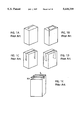
FIGS. 1A to 1E are perspective views of the configurations of a series of prior art antennas;
FIGS. 2 is a perspective view of a horizontal-U shaped antenna of the present invention;
FIGS. 3 is a perspective view of another horizontal-U shaped antenna of the present invention attached to a containing box;
FIGS. 4 is a perspective view of a horizontal-U shaped antenna of FIG. 2 which being divided into a plurality of cells for numerical analysis of the present invention;
FIGS. 5 is a perspective view of a horizontal-U shaped antenna of FIG. 3 which being divided into a plurality of cells for numerical analysis of the present invention;
FIG. 6 shows the variations of the input conductance and susceptance as function of frequency of the antenna of FIG. 2;
FIG. 7 shows the variations of the input conductance and susceptance as function of frequency of the antenna of FIG. 3 without the containing box;
FIG. 8 shows the variations of the input conductance and susceptance as function of frequency of the antenna of FIG. 3 with the containing box;
FIG. 9 shows the variations of the input conductance and susceptance as function of frequency of the antenna of FIG. 2 with feed probe placed at different positions;
FIG. 10 shows the variations of the input conductance and susceptance as function of frequency of the antenna of FIG. 2 with feed probes of different diameters;
FIG. 11 shows the variations of the reflection coefficient as function of frequency of the antennas of FIG. 2 and FIG. 3;
FIG. 12 shows the variations of the reflection coefficient as function of frequency of the antenna of FIG. 3 with uniform opening slot and tapered opening slot;,
FIG. 13 shows the variations of the reflection coefficient as function of frequency of another antenna with and without the containing box;
FIG. 14 shows the current distribution on the surface of the antenna of FIG. 2 at two resonant frequencies;
FIG. 15 shows the current distribution on the surface of the antenna of FIG. 3 at two resonant frequencies;
FIG. 16 is a flowchart showing a design procedure for a multiple resonance horizontal U-shaped antenna applying a full wavelength equivalent circuit technique of this invention;
FIGS. 17a to 17c show the cell elements used in the full wavelength equivalent circuit technique of this invention; and
FIGS. 18a and 18b shows the surface current in a cell element and the equivalent circuits for the full wavelength equivalent circuit technique of this invention.
DETAILED DESCRIPTION OF THE PREFERRED EMBODIMENT
FIG. 2 shows a new multi-resonance horizontal-U antenna 100 of the present invention before the antenna is attached to a box for containing communication system, e.g., a wireless telephone. The horizontal-U antenna 100 includes a base plate 110 of length L6 and two horizontal antenna arms 115 and 120 with arm lengths of L1 and L2 respectively. Each of these horizontal antenna arms 115 and 120 are connected to the base plate 110 via a side plate 122 and 124 respectively. A set of preferred dimensions of the antenna 100 are shown wherein the lengths L1, L2, and L6 are all of different values. The feedline 125 from the communication system is extended from a via 130 on the base plate 110 to be in contact with the horizontal antenna arm 120.
FIG. 3 shows another preferred embodiment of the present invention where a multi-resonance horizontal-U antenna 200 is provided to be attached to a box 250 for containing a communication system therein. Similar to the horizontal-U antenna 100 as shown in FIG. 1, the horizontal-U antenna 200 also includes a base plate 210 and two horizontal antenna arms 215 and 220 which are connected to the base plate 210 via two side plates 222 and 224 respectively. A set of dimensions of a preferred embodiment is shown in FIG. 2 also. The upper cover of the box 250 is composed of plastic material such that minimum interference is caused by the upper cover which is right underneath the base plate 210. Other parts of the containing box 210 are composed of material coated with metallic paints to function as electromagnetic wave, i.e., E-M wave, radiating body.
In a preferred embodiment, the present invention discloses a horizontal-U shaped antenna 100 which includes a conductive base plate 110 including two vertically side plates 122 and 124 extending upwardly from one edge of the base plate 110. The antenna 100 further includes two horizontal conductive antenna arms 115 and 120 of unequal lengths each connected to a corresponding side plate 122 and 124 respectively, extending horizontally over the base plate 110. The two horizontal conductive antenna arms 115 and 120 of unequal lengths and the two corresponding side plates 122 and 124 connected thereto further are separated by an opening slot,
In order to more fully appreciate the advantages and the underlying physics of these novel and improved antenna configurations, a new analytical model is first described. The performance parameters of the antenna of this invention are first computed by the use of this new analytical model. Results of actual measurements are then compared with the calculated data. The computational results in combination with the actual measurements present clear explanations and proofs that (1) the antenna of this invention is superior in performance and is able to provide more design flexibility, and (2) the new analytical is more accurate and require less computer time and thus providing better design techniques for use in modern antenna design processes.
Instead of dividing an antenna into a plurality of `wire grids` and simulating the currents flowing through these wires, the antenna is now managed as it is formed with a plurality of `cells` in a new analytical model i.e., the full wave equivalent circuit model. The cells can be rectangles, triangles, or even a wire. The antennas of the present invention as that shown in FIGS. 2 and 3 can be modeled as FIGS. 4 and 5 respectively. The details of the full wave equivalent circuit model including the electromagnetic equations employed to model the antenna as equivalent circuits are presented in Appendix A.
The calculated and measured input conductance and input susceptance for the multi-resonant horizontal-U antenna 100 is shown in FIG. 6. It is very clear that antenna 100 has two resonant modes. The first resonant mode occurs at 1.87 GHz and the second resonant mode occurs around 2.17 GHz. Similar to FIG. 6, FIGS. 7 and 8 show the input conductance and input susceptance for the antenna 200 without and with the containing box respectively. In examining the data shown in these two figures, it is found that as a result of adding the containing box, the first resonance frequency is changed from 1.605 GHz to 1.7 GHz, and the second resonance frequency is changed from 2.17 to 1.95 GHz. As these two resonance frequencies are drawn closer, the bandwidth is expanded. FIG. 9 shows the variation of calculated input conductance and input susceptance as function of the feed probe positions, i.e., yf when all other parameters are maintained the same. The relative frequency difference between two resonant frequencies remains substantially unchanged while the two resonant frequencies move higher as yf is increased. FIG. 10 shows the variation of calculated input conductance and input susceptance as function of the diameter of the feed probe. The first resonant frequency moves higher as the diameter of the feed prove is increased while the second resonant frequency does not change.
As the bandwidth is defined as the value of voltage standing wave ratio (VSWR) less than 2.0, or the reflection coefficient, i.e., S11, is less than -10 dB. FIG. 11A shows the reflection coefficient for antenna 100 (FIG. 2) where a 20% is achieved around a resonant frequency around 1.9 GHz, and FIG. 11B shows the reflection coefficient for antenna 200 (FIG. 3) wherein two curves are shown for the reflection coefficient of antenna 200 with and without the containing box respectively and a bandwidth of about 25% is achieved. FIG. 12A and FIG. 12B show the reflection coefficient of the antenna 200 with uniform slot and tapered slot respectively. In FIG. 12A, the reflection coefficient between 1.7 and 1.8 GHz is greater than -10 dB and this section of bandwidth is not useful. By varying the slot S2 from 0.1 cm to 0.65 cm, that limitation is removed. FIG. 12B further shows that the containing box tends to lower the resonance frequencies and also improve the bandwidth. As shown in Table 1 below, seven sets of dimensions, i.e., design A, to B5 are employed for designing the antenna for determination of antenna performance characteristics where type A is for antenna along and type B is for antennas designed with a box for containing a cordless phone therein. It is noted that B5 is for a horizontal-U shaped antenna where there is no opening slot between two horizontal upper arms. An example of the reflection coefficient for design B2 is shown in FIG. 13 where a bandwidth greater than 25% is achieved.
FIGS. 14A and 14B show the current distributions, at frequencies 1.87 GHz and 2.16 GHz respectively, on the surface of the base plate 110, two horizontal antenna arms 115 and 120, and two side plates 122 and 124 of a type A antenna 100 in FIG. 2. At frequency 1.87 GHz, the currents in two horizontal antenna arms 115 and 120 are in opposite directions while at 2.16 GHz they are in the same direction. The first resonance is induced by the currents in the two horizontal antenna arms 115 and 120 wherein L1+L2 is approximately λ/2. While the second resonance is induced by the first antenna arm 115 and the base plate 110, thus L1+L6 is approximately λ/2. FIGS. 15A and 15B show the current distributions, at frequencies 1.605 GHz and 2.17 GHz respectively, on the surface of the base plate 210, two horizontal antenna arms 215 and 220, and two side plates 222 and 224 of a type B antenna 200 in FIG. 3. At frequency 1.605 GHz, the currents in two horizontal antenna arms 215 and 220 are in opposite directions while at 2.17 GHz they are in the same direction. The first resonance is induced by the currents in the two horizontal antenna arms 215 and 220 wherein L1+L2 is approximately λ/2. While at the second resonance frequency 2.17 GHz, the current density on arm 220 is greater than 215 thus the resonance is more related to arm 220 than arm 215. The second resonance is induced by the current flow from the base plate 210 through the feed probe to the second arm 220 and forming a length of approximately half wave length, i.e., (L2 -yf)+h5 +(L6 -yf)=λ/2 where yf is the distance between the contact point of the feed probe from the edge of the horizontal arm connected to the side plates 222 and 224.
For a multiple-resonance horizontal U-shaped antenna, the full wave length analysis technique as outlined above can be employed to simplify the design process and to optimize the design parameters as that shown in a flow chart in FIG. 16. The process begins (step 300) by making a preliminary selection of the lengths of the base plate, the horizontal antenna arms, e.g., L1, L2, and L6, and the position of the feed probe (step 310). The preliminary selection is be guided by the equations either L1+L2 is approximately to be λ/2 or (L2 -yf)+h5 +(L6 -yf) =λ/2. A full wavelength equivalent circuit analysis is then performed (step 320) to calculate the performance parameters such as the resonance frequencies, bandwidth, input impedance and radiation pattern. Based on the calculated results, the geometrical parameters of the antenna are then adjusted and further analyses are performed iteratively to optimize the antenna performance depending on the operation requirement specification of the antenna (step 330). An experiment is then carried out to confirm the performance based on the analysis data (step 340). Further adjustments are made to fine tune the design (step 350) before the design process is completed (step 360). A design is then provided with an effective design process by the use of the full wavelength equivalent technique to achieve optimal design of an antenna in a predictable and controllable manner.
This invention also discloses a method of generating multiple-resonance modes of operation in a horizontal-U shaped antenna which includes a conductive base plate of length L6 having two vertically side plates extending upwardly from one edge of the base plate and two horizontal conductive antenna arms of unequal lengths L1 and L2 respectively each connected to a corresponding side plate and extending horizontally over the base plate. The method includes a step of adjusting the lengths of the L1, L2 and L6 whereby L1+L2 and L1+L6 are both approximately half of the wavelength λ corresponding to a main resonance frequency.
A method of generating multiple-resonance mode of operation in a horizontal-U shaped antenna is also disclosed in this invention which includes thereof: (a) forming a base plate having multiple vertically side plates extending upwardly from one edge of the base plate; (b) forming multiple horizontal conductive antenna arms corresponding to each of the vertical side plates each being of unequal length and being connected to the corresponding side plate and extending horizontally over the base plate; and (c) adjusting the lengths of the base plates and each of the horizontal antenna arms for achieving the multiple-resonance mode of operation.
This invention further discloses a method of designing a multiple-resonance horizontal-U shaped antenna which includes a base plate having multiple vertically side plates extending upwardly from one edge of the base plate and multiple horizontal conductive antenna arms corresponding to each of the vertical side plates each being of unequal length and being connected to the corresponding side plate and extending horizontally over the base plate. This method can be computerized such that automated design procedure can be carried out to achieve savings of human efforts. The method includes the steps of: (a) making a preliminary selection of a plurality of geometrical parameters of the antenna, e.g., step 310; (b) performing a full wavelength equivalent circuit analysis with the geometrical parameters for the antenna for obtaining several performance variables, e.g., step 320; (c) comparing the performance variables with a set of targeted performance variables; and (d) adjusting the lengths of the base plates and each of the horizontal antenna arms for achieving an optimal design wherein the performance variables being most approximating to the target performance variables, i.e., step 350.
This invention thus discloses a novel design of high frequency hidden hand-held antenna which includes two metal arms above a lower arm of finite ground plane. By properly choosing the lengths of these arms and the separations between them, the bandwidth can be broadened more than 20%. Thus, it is suitable for personal mobile communication applications. A full wave equivalent circuit analytic model is also developed to analyze and optimize the geometrical configuration including the lengths and separations between the arms. Numerical analyses for current distribution on the conductor surface and various antenna characteristics such as input impedance and radiation patterns are computed by the use of the analytical models. Experimental results and numerical computations all confirm that better performance characteristics including broadened antenna bandwidth are achieved by this novel antenna.
Although the present invention has been described in terms of the presently preferred embodiment, it is to be understood that such disclosure is not to be interpreted as limiting. Various alternations and modifications will no doubt become apparent to those skilled in the art after reading the above disclosure. Accordingly, it is intended that the appended claims be interpreted as covering all alternations and modifications as fall within the true spirit and scope of the invention.
              TABLE 1*                                                    
______________________________________                                    
PARAMETER\                                                      
Type        A      B      B1   B2   B3   B4   B5**                        
______________________________________                                    
L1          2.8    4.8    6.1  5.8  4.3  5.0  4.8                         
W1          .45    .45    .45  .45  .45  .45  N/A                         
L2          5.27   4.7    4.8  4.8  4.3  5.0  4.8                         
W2          .45    .45    .45  .45  .45  .45  N/A                         
h34         0.5    0.5    0.5  0.5  1.0  0.3  0.5                         
W34         .45    .45    .45  .45  .45  .45  N/A                         
h5          0.5    0.5    0.5  0.5  1.0  0.3  0.5                         
L6          4.0    3.4    3.4  3.3  3.4  3.4  3.4                         
W6          1.0    1.0    1.0  1.0  1.0  1.0  1.0                         
yf          1.0    1.0    1.0  1.0  1.0  1.0  1.0                         
s1          0.1    0.1    0.1  0.1  0.1  0.1  0                           
s2          0.1    0.65   0.45 0.25 0.1  0.1  0                           
bx          N/A    3.5    3.5  3.5  3.5  3.5  3.5                         
by          N/A    6.0    6.0  6.0  6.0  6.0  6.0                         
bz          N/A    20.0   20.0 20.0 20.0 20.0 20.0                        
______________________________________                                    
 *All parameters have dimensions defined in CM                            
 **B5 is a type which has no opening slot.                                
Appendix A
The current J(r) on the surface of the multi-resonant horizontal-U shaped antenna 100 as that shown in FIG. 4 can be expressed as:
E.sup.s (r)=-jωA(r)-∇Φ(r)               (A-1)
and the magnetic vector potential A(r) and the electric scalar potential Φ(r) can be represented as ##EQU1## where R=|r-r'| which is the distance between the source of the electromagnetic (E-M) wave r' and the position of observation r. The charge density ρ(r) may be obtained as:
ρ(r)=(-1/jω)∇s·J(r)            (A-4)
where ∇s represents a derivative on the surface of the conductive metal.
The tangential component of total electrical field over the surface of the metal surface satisfies a condition represented by:
E.sub.t.sup.i (r)+E.sub.t.sup.s (r)=Z.sub.s J(r)           (A-5)
where the subscript t representing a tangent component and Ei (r) defines the incident electrical field from the E-M wave source. And, ##EQU2## which is surface impedance. The solution for the surface current J(r) can be obtained by substituting equations A-1 to A-4 into Equation A-5.
In order to obtain the value of J(r), the metal surface is divided Into many cell elements and the current in each cell is then represented as simple functions which approximate the current density. As shown in FIG. 17a to 17c, there are three kinds of cell elements, i.e., a wire cell, a triangle cell, and a rectangular cell. For the modeling of the U-shaped antenna, majority of the cells are rectangular cells, while the intersection parts between the base plate and vertical arms are modeled by the use of triangle cells. The feed probe is modeled by the use of wire cells. The following descriptions provide equations for modeling these different types of cells:
I. Wire Cell Model
As shown in FIG. 17a, the length of the line is l and the diameter is d, and the current density can be defined as:
J(s)=I.sub.1 B.sub.1 (s)+I.sub.2 B.sub.2 (s)               (A-7)
where s representing a coordinate along the line and the basis functions can be defined as: ##EQU3## When an integration of the basis functions are performed along the edge at the end portion, the unknowns I1 and I2 in Equation A-7 may be represented as the current outputs. The charge density corresponding to the current density obtained from the basis function can be derived from Equation A-4 as:
ρ(s)=Q·II(s)
where ##EQU4## A is the total area of the wire and the coefficient Q can be defined as: ##EQU5## is the total charge of this wire cell element.
II. Rectangular Cell Element
As shown in FIG. 17b, the dimension of the rectangle is a by b and the current can be represented as: ##EQU6## It can be noted that when an integration is performed over any side of the rectangle, e.g., Γ1, for the basis function B1, the following condition exists: ##EQU7## as to the other sides of the rectangle, i.e., Γ1 where i≠1, the coefficient for Ii where i=1,2,3, and 4, in Equation A-8 is equivalent to the total current output from that side. Therefore, the total charge density corresponding to the total current can be obtained by:
ρ(ξ·η)=Q·II(ξ,η)
where the base function for the total charge can be derived from: ##EQU8## Similarly, A represents the total area of this cell and the total charge Q can be obtained as:
Q=-(1/jω)(I.sub.1 +I.sub.2 +I.sub.3 +I.sub.4)
III. Triangle Cell Element
As shown in FIG. 17c, the three points defining the triangle are located at r1, r2 and r3 whereas three sides are Γ1, Γ2, and Γ3. The current inside the triangle can be represented as: ##EQU9## where
B.sub.i (r)=(r-r.sub.i)/2A where i=1, 2, 3
and A is the area of this triangle. The integration performed over each side is: ##EQU10## thus the coefficients Ii in Equation (A-9) represent the total current output from each side Γi of the triangle, and the charge density is:
ρ(r)=Q·II(r)
where
II(r)=∇s·B.sub.i (r)-1/A (i=1,2,3)
and the total charge Q in the triangle cell is:
Q=-(1/jω) (I.sub.1 +I.sub.2 +I.sub.3)
IV. Current Connection Matrix
As the antenna includes many different types of cell elements, assuming that the term BPi (r) is a vector basis representing the current on a boundary line ΓPi of a cell element Ωp and IPi representing the total current flow on that boundary line ΓPi of that cell element Ωp. This current will flow into a boundary line of a next cell, e.g., q-th cell, thus, Ipi =-Iqj. A branch current can be defined as In =Ipi =-Iqj. The basis function Bn (r) can therefore be represented as functions of BPi (r) and --Bqj (r): ##EQU11## where N is the number of total branches and [T] is a current branch matrix consisting of matrix elements Tnpi =1 if the n-th branch current flows out of the i-th side of the p-th cell, Tnpi =-1 if the n-th branch current flows into the i-th side of the p-th cell, and Tnpi =0 if other than the above two conditions.
V. Equations for Full wavelength Equivalent Circuit
Moment method is often used for solving Equation A-5. By substituting Equation A-1 into Equation A-5, a functional relationship can be represented as:
∫B.sub.m (r)·E.sub.t.sup.i (r)dΩ-jω∫B.sub.m (r)·A(r)d Ω-∫B.sub.m (r)·∇Φ(r)dΩ=Z.sub.s ∫B.sub.m (r)·J(r)dΩ                                 (A-12)
The third term can be simplified by the divergence theorem as: ##EQU12## On a boundary line Γ, the basis function for a cell element has the characteristic that n·Bm (r) has a value of zero. The line integration portion can be neglected. The magnetic vector potential A(r) and the electric scalar potential Φ(r) in the above equation can be represented as function of J(r) by the use of Equations (A-2) to (A-4). And the current function J(r) can be further expressed as function of the basis functions of each cell. ##EQU13## representing an input voltage. In Equation A-14, when the frequency is low e-jkR ≈1, where Lqi,pi is a partial inductance between the bases Bqj (r) and Bpi (r) and Cqp represents a partial capacitance between the q-th and p-th cells. As the frequency increases, the phase retarded term e-jkR can not be neglected where the inductance and the capacitance are all complex numbers and may be termed as the full wavelength inductance and capacitance.
The analyses can be carried out by including these equivalent components. FIG. 18b is a diagram showing such an equivalent circuit. By the use of the KVL method, and assuming that a branch current is flowing from a m-th branch on a J+ side of a q+ -th cell into j- side of a q- cell branch while the current on an n-th branch is from a i+ side of a p+ cell flowing into a i- side of a p- cell, then in a m-th loop: ##EQU14## which is consistent with Equation A-14.
Please refer to FIG. 18a for an input voltage source added to a m-th branch, the potential Vm is imposed on a gap with width of Δ where the electric field is about: ##EQU15## The first term in Equation A-12 can be defined as: ##EQU16## Which is consistent with the results obtained above. For the purposes of solving Equations A-14 and A-15, other than an input point, the input voltage, Vm, should be maintained at a zero value.
VI. Input Impedance and Radiation Pattern
When the branch currents are solved with appropriate input voltages in different branches, the impedance with respect to the antenna input is:
Z.sub.in =V.sub.m /I.sub.m                                 (A- 18)
Meanwhile, the electric field at any point r in the space can be obtained by the use of Equations A-1 to A-3, and when it is remote from the current source, |r|=r→∞
R=|r-r'|≅r-r·r'
and the radiation pattern can be obtained by: ##EQU17##

Claims (8)

We claim:
1. A horizontal-U shaped antenna provided for application with a signal transmitting and receiving device, said antenna comprising: a conductive base plate including two vertically side plates extending upwardly from one edge of said base plate;
two horizontal conductive antenna arms of unequal lengths each connected to a corresponding side plate extending horizontally over said base plate; and
said conductive base plate is further provided to be electrically insulated from said signal transmitting and receiving device whereby a plurality of resonance currents are induced in said conductive base plate, said vertical side plates and said horizontal conductive antenna arms to generate a plurality of antenna resonant frequencies.
2. The antenna of claim 1 wherein:
said two horizontal conductive antenna arms of unequal lengths and said two corresponding side plates connected thereto further are separated by an opening slot.
3. The antenna of claim 2 wherein:
said opening slot further being tapered having a narrower opening near said plates and having an opening which being gradually widened therefrom.
4. The antenna of claim 1 further comprising:
a containing box for containing said signal transmitting and receiving device therein;
said containing box further including an upper cover; and
said base plate being securely attached to and electrically insulated from said upper cover of said containing box.
5. A horizontal-U shaped antenna provided for application with a signal transmitting and receiving device, said antenna comprising:
a conductive base plate including two vertically side plates extending upwardly from one edge of said base plate;
two horizontal conductive antenna arms of unequal lengths each connected to a corresponding side plate extending horizontally over said base plate;
said two horizontal conductive antenna arms of unequal lengths and said two corresponding side plates connected thereto further are separated by an opening slot;
said opening slot further being tapered having a narrower opening near said plates and having an opening which being gradually widened therefrom;
a containing box for containing said signal transmitting and receiving device therein;
said containing box further including an upper cover; and
said base plate being securely attached to and electrically insulated from said upper cover of said containing box and being electrically insulated from said signal transmitting and receiving device whereby a plurality of resonance currents are induced in said conductive base plate, said vertical side plates and said horizontal conductive antenna arms to generate a plurality of antenna resonant frequencies.
6. A method of generating multiple-resonance modes of operation in a horizontal-U shaped antenna including a conductive base plate of length L6 having two vertically side plates extending upwardly from one edge of said base plate and two horizontal conductive antenna arms of unequal lengths L1 and L2 respectively each connected to a corresponding side plate and extending horizontally over said base plate, said method including a step of:
(a) providing an insulation means to said horizontal-U shaped antenna for substantially insulating said antenna from external interference; and
(b) adjusting the lengths of said L1, L2 and L6 whereby L1+L2 and L1+L6 are both approximately half of the wavelength λ corresponding to a main resonance frequency.
7. A method of generating multiple-resonance mode of operation in a horizontal-U shaped antenna comprising the steps of:
(a) forming a base plate having multiple vertically side plates extending upwardly from one edge of said base plate;
(b) forming multiple horizontal conductive antenna arms corresponding to each of said vertical side plates each being of unequal length and being connected to said corresponding side plate and extending horizontally over said base plate; and
(c) adjusting the lengths of said base plates and each of said horizontal antenna arms for achieving said multiple-resonance mode of operation; and
(d) providing an insulation means to said horizontal-U shaped antenna for substantially insulating said base plate from a ground potential whereby a plurality of resonance currents may be induced in said base plate, said vertical side plates and said horizontal conductive antenna arms to generate a plurality of antenna resonant frequencies.
8. A method of designing a multiple-resonance horizontal-U shaped antenna for application with a signal transmitting and receiving device, wherein said antenna including a base plate having multiple vertically side plates extending upwardly from one edge of said base plate and multiple horizontal conductive antenna arms corresponding to each of said vertical side plates each being of unequal length and being connected to said corresponding side plate and extending horizontally over said base plate wherein said base plate is provided to be electrically insulated from said signal transmitting and receiving device, the method comprising the steps of:
(a) making a preliminary selection of a plurality of geometrical parameters of said antenna;
(b) performing a full wavelength equivalent circuit analysis with said geometrical parameters for said antenna for obtaining several performance variables;
(c) comparing said performance variables with a set of targeted performance variables; and
(d) adjusting the lengths of said base plates and each of said horizontal antenna arms for achieving an optimal design wherein said performance variables being most approximating to said target performance variables.
US08/455,916 1995-05-31 1995-05-31 Multi-resonance horizontal-U shaped antenna Expired - Lifetime US5644319A (en)

Priority Applications (1)

Application Number Priority Date Filing Date Title
US08/455,916 US5644319A (en) 1995-05-31 1995-05-31 Multi-resonance horizontal-U shaped antenna

Applications Claiming Priority (1)

Application Number Priority Date Filing Date Title
US08/455,916 US5644319A (en) 1995-05-31 1995-05-31 Multi-resonance horizontal-U shaped antenna

Publications (1)

Publication Number Publication Date
US5644319A true US5644319A (en) 1997-07-01

Family

ID=23810745

Family Applications (1)

Application Number Title Priority Date Filing Date
US08/455,916 Expired - Lifetime US5644319A (en) 1995-05-31 1995-05-31 Multi-resonance horizontal-U shaped antenna

Country Status (1)

Country Link
US (1) US5644319A (en)

Cited By (49)

* Cited by examiner, † Cited by third party
Publication number Priority date Publication date Assignee Title
WO1998044588A1 (en) * 1997-03-31 1998-10-08 Qualcomm Incorporated Dual-frequency-band patch antenna with alternating active and passive elements
EP0911988A2 (en) * 1997-10-23 1999-04-28 Kyocera Corporation Antenna connection for a portable radio
WO1999033144A1 (en) * 1997-12-22 1999-07-01 Nokia Mobile Phones Limited Antenna
GB2333902A (en) * 1998-01-31 1999-08-04 Nec Technologies Directive antenna for mobile telephones
US5943019A (en) * 1996-02-19 1999-08-24 Murata Manufacturing Co., Ltd. Method of mounting surface mounting antenna on mounting substrate antenna apparatus and communication apparatus employing mounting substrate
WO1999043045A1 (en) * 1998-02-23 1999-08-26 Qualcomm Incorporated Antenna with two active radiators
US6008762A (en) * 1997-03-31 1999-12-28 Qualcomm Incorporated Folded quarter-wave patch antenna
US6114996A (en) * 1997-03-31 2000-09-05 Qualcomm Incorporated Increased bandwidth patch antenna
FR2791815A1 (en) * 1999-04-02 2000-10-06 Rene Liger Compact metallic plate UHF antenna, e.g. for small transponders, has folded trihedral structure with horizontal and vertical sections forming ground planes and inclined section acting as radiator
US6140966A (en) * 1997-07-08 2000-10-31 Nokia Mobile Phones Limited Double resonance antenna structure for several frequency ranges
US6218991B1 (en) 1999-08-27 2001-04-17 Mohamed Sanad Compact planar inverted F antenna
WO2001057952A1 (en) * 2000-02-04 2001-08-09 Rangestar Wireless, Inc. Dual frequency wideband resonator
US6307512B1 (en) * 1998-12-22 2001-10-23 Nokia Mobile Phones Limited Dual band antenna for a handset
US6339402B1 (en) * 1999-12-22 2002-01-15 Rangestar Wireless, Inc. Low profile tunable circularly polarized antenna
US6429818B1 (en) * 1998-01-16 2002-08-06 Tyco Electronics Logistics Ag Single or dual band parasitic antenna assembly
US6456249B1 (en) 1999-08-16 2002-09-24 Tyco Electronics Logistics A.G. Single or dual band parasitic antenna assembly
US20020151328A1 (en) * 2001-04-11 2002-10-17 Lg Electronics Inc. Internal display-mounted antenna for mobile electronic equipment and mobile electronic equipment incorporating same
US6542123B1 (en) * 2001-10-24 2003-04-01 Auden Techno Corp. Hidden wideband antenna
US20030124985A1 (en) * 2001-04-11 2003-07-03 Shin Hyo Sik Multi-band antenna and notebook computer with built-in multi-band antenna
US20030222823A1 (en) * 2001-05-29 2003-12-04 International Business Machines Corporation Integrated dual-band antenna for laptop applications
US20030227351A1 (en) * 2002-05-15 2003-12-11 Hrl Laboratories, Llc Single-pole multi-throw switch having low parasitic reactance, and an antenna incorporating the same
US6683575B2 (en) * 2001-07-05 2004-01-27 Kabushiki Kaisha Toshiba Antenna apparatus
US20040125025A1 (en) * 2000-04-27 2004-07-01 Warren Stutzman Wideband compact planar inverted- f antenna
US20040227668A1 (en) * 2003-05-12 2004-11-18 Hrl Laboratories, Llc Steerable leaky wave antenna capable of both forward and backward radiation
US20040227678A1 (en) * 2003-05-12 2004-11-18 Hrl Laboratories, Llc Compact tunable antenna
US20040227667A1 (en) * 2003-05-12 2004-11-18 Hrl Laboratories, Llc Meta-element antenna and array
US20050251798A1 (en) * 2004-05-05 2005-11-10 News, Iq, Inc. System and method for inventory control and management
US20060071871A1 (en) * 2004-10-05 2006-04-06 Industrial Technology Research Institute Omnidirectional ultra-wideband monopole antenna
US20060082505A1 (en) * 2003-02-19 2006-04-20 Baliarda Carles P Miniature antenna having a volumetric structure
US20060125703A1 (en) * 2004-12-14 2006-06-15 Intel Corporation Slot antenna having a MEMS varactor for resonance frequency tuning
US7154451B1 (en) 2004-09-17 2006-12-26 Hrl Laboratories, Llc Large aperture rectenna based on planar lens structures
US20070146213A1 (en) * 2005-12-28 2007-06-28 Fujitsu Limited Antenna, method of adjusting resonance frequency thereof, and wireless communication device
US7245269B2 (en) 2003-05-12 2007-07-17 Hrl Laboratories, Llc Adaptive beam forming antenna system using a tunable impedance surface
US7253699B2 (en) 2003-05-12 2007-08-07 Hrl Laboratories, Llc RF MEMS switch with integrated impedance matching structure
US7276990B2 (en) 2002-05-15 2007-10-02 Hrl Laboratories, Llc Single-pole multi-throw switch having low parasitic reactance, and an antenna incorporating the same
US7307589B1 (en) 2005-12-29 2007-12-11 Hrl Laboratories, Llc Large-scale adaptive surface sensor arrays
US20070290944A1 (en) * 2006-04-10 2007-12-20 Hitachi Metals, Ltd. Antenna device and multi-band type wireless communication apparatus using same
US7456803B1 (en) 2003-05-12 2008-11-25 Hrl Laboratories, Llc Large aperture rectenna based on planar lens structures
US20090318094A1 (en) * 2006-06-08 2009-12-24 Fractus, S.A. Distributed antenna system robust to human body loading effects
US7868829B1 (en) 2008-03-21 2011-01-11 Hrl Laboratories, Llc Reflectarray
US8436785B1 (en) 2010-11-03 2013-05-07 Hrl Laboratories, Llc Electrically tunable surface impedance structure with suppressed backward wave
US8982011B1 (en) 2011-09-23 2015-03-17 Hrl Laboratories, Llc Conformal antennas for mitigation of structural blockage
US8994609B2 (en) 2011-09-23 2015-03-31 Hrl Laboratories, Llc Conformal surface wave feed
US20150238114A1 (en) * 2014-02-27 2015-08-27 Kimberly-Clark Worldwide, Inc. Methods for Assessing Health Conditions Using Single Coil Magnetic Induction Tomography Imaging
US9442088B2 (en) 2014-02-27 2016-09-13 Kimberly-Clark Worldwide, Inc. Single coil magnetic induction tomographic imaging
US9466887B2 (en) 2010-11-03 2016-10-11 Hrl Laboratories, Llc Low cost, 2D, electronically-steerable, artificial-impedance-surface antenna
US9903736B2 (en) 2014-09-18 2018-02-27 Arad Measuring Technologies Ltd. Utility meter having a meter register utilizing a multiple resonance antenna
US10236561B2 (en) 2014-07-24 2019-03-19 Fractus Antennas, S.L. Slim booster bars for electronic devices
WO2020239544A1 (en) 2019-05-29 2020-12-03 Robert Bosch Gmbh An antenna system

Citations (6)

* Cited by examiner, † Cited by third party
Publication number Priority date Publication date Assignee Title
US4584585A (en) * 1984-04-04 1986-04-22 Motorola, Inc. Two element low profile antenna
US4641366A (en) * 1984-10-04 1987-02-03 Nec Corporation Portable radio communication apparatus comprising an antenna member for a broad-band signal
US4876552A (en) * 1988-04-27 1989-10-24 Motorola, Inc. Internally mounted broadband antenna
US5144324A (en) * 1989-08-02 1992-09-01 At&T Bell Laboratories Antenna arrangement for a portable transceiver
EP0604338A1 (en) * 1992-12-23 1994-06-29 France Telecom Space-saving broadband antenna with corresponding transceiver
US5365246A (en) * 1989-07-27 1994-11-15 Siemens Aktiengesellschaft Transmitting and/or receiving arrangement for portable appliances

Patent Citations (6)

* Cited by examiner, † Cited by third party
Publication number Priority date Publication date Assignee Title
US4584585A (en) * 1984-04-04 1986-04-22 Motorola, Inc. Two element low profile antenna
US4641366A (en) * 1984-10-04 1987-02-03 Nec Corporation Portable radio communication apparatus comprising an antenna member for a broad-band signal
US4876552A (en) * 1988-04-27 1989-10-24 Motorola, Inc. Internally mounted broadband antenna
US5365246A (en) * 1989-07-27 1994-11-15 Siemens Aktiengesellschaft Transmitting and/or receiving arrangement for portable appliances
US5144324A (en) * 1989-08-02 1992-09-01 At&T Bell Laboratories Antenna arrangement for a portable transceiver
EP0604338A1 (en) * 1992-12-23 1994-06-29 France Telecom Space-saving broadband antenna with corresponding transceiver

Cited By (85)

* Cited by examiner, † Cited by third party
Publication number Priority date Publication date Assignee Title
US5943019A (en) * 1996-02-19 1999-08-24 Murata Manufacturing Co., Ltd. Method of mounting surface mounting antenna on mounting substrate antenna apparatus and communication apparatus employing mounting substrate
US6114996A (en) * 1997-03-31 2000-09-05 Qualcomm Incorporated Increased bandwidth patch antenna
WO1998044588A1 (en) * 1997-03-31 1998-10-08 Qualcomm Incorporated Dual-frequency-band patch antenna with alternating active and passive elements
US6008762A (en) * 1997-03-31 1999-12-28 Qualcomm Incorporated Folded quarter-wave patch antenna
US6140966A (en) * 1997-07-08 2000-10-31 Nokia Mobile Phones Limited Double resonance antenna structure for several frequency ranges
EP0911988A2 (en) * 1997-10-23 1999-04-28 Kyocera Corporation Antenna connection for a portable radio
EP0911988A3 (en) * 1997-10-23 2003-08-06 Kyocera Corporation Antenna connection for a portable radio
GB2347275B (en) * 1997-12-22 2002-08-14 Nokia Mobile Phones Ltd Antenna
WO1999033144A1 (en) * 1997-12-22 1999-07-01 Nokia Mobile Phones Limited Antenna
US6160513A (en) * 1997-12-22 2000-12-12 Nokia Mobile Phones Limited Antenna
GB2347275A (en) * 1997-12-22 2000-08-30 Nokia Mobile Phones Ltd Antenna
US6429818B1 (en) * 1998-01-16 2002-08-06 Tyco Electronics Logistics Ag Single or dual band parasitic antenna assembly
GB2333902B (en) * 1998-01-31 2002-10-23 Nec Technologies Directive antenna for mobile telephones
GB2333902A (en) * 1998-01-31 1999-08-04 Nec Technologies Directive antenna for mobile telephones
KR100721742B1 (en) * 1998-02-23 2007-05-25 퀄컴 인코포레이티드 Dual strip antenna
US6184833B1 (en) * 1998-02-23 2001-02-06 Qualcomm, Inc. Dual strip antenna
WO1999043045A1 (en) * 1998-02-23 1999-08-26 Qualcomm Incorporated Antenna with two active radiators
AU762189B2 (en) * 1998-02-23 2003-06-19 Qualcomm Incorporated Antenna with two active radiators
US6307512B1 (en) * 1998-12-22 2001-10-23 Nokia Mobile Phones Limited Dual band antenna for a handset
FR2791815A1 (en) * 1999-04-02 2000-10-06 Rene Liger Compact metallic plate UHF antenna, e.g. for small transponders, has folded trihedral structure with horizontal and vertical sections forming ground planes and inclined section acting as radiator
US6456249B1 (en) 1999-08-16 2002-09-24 Tyco Electronics Logistics A.G. Single or dual band parasitic antenna assembly
US6218991B1 (en) 1999-08-27 2001-04-17 Mohamed Sanad Compact planar inverted F antenna
US6339402B1 (en) * 1999-12-22 2002-01-15 Rangestar Wireless, Inc. Low profile tunable circularly polarized antenna
WO2001057952A1 (en) * 2000-02-04 2001-08-09 Rangestar Wireless, Inc. Dual frequency wideband resonator
US20040125025A1 (en) * 2000-04-27 2004-07-01 Warren Stutzman Wideband compact planar inverted- f antenna
USRE42672E1 (en) 2000-04-27 2011-09-06 Virginia Tech Intellectual Properties, Inc. Wideband compact planar inverted-F antenna
US6795028B2 (en) * 2000-04-27 2004-09-21 Virginia Tech Intellectual Properties, Inc. Wideband compact planar inverted-F antenna
US6957085B2 (en) * 2001-04-11 2005-10-18 Lg Electronics Inc Internal display-mounted antenna for mobile electronic equipment and mobile electronic equipment incorporating same
US7072690B2 (en) 2001-04-11 2006-07-04 Lg Electronics Inc. Multi-band antenna and notebook computer with built-in multi-band antenna
US20030124985A1 (en) * 2001-04-11 2003-07-03 Shin Hyo Sik Multi-band antenna and notebook computer with built-in multi-band antenna
US20020151328A1 (en) * 2001-04-11 2002-10-17 Lg Electronics Inc. Internal display-mounted antenna for mobile electronic equipment and mobile electronic equipment incorporating same
US20030222823A1 (en) * 2001-05-29 2003-12-04 International Business Machines Corporation Integrated dual-band antenna for laptop applications
US8294620B2 (en) * 2001-05-29 2012-10-23 Lenovo (Singapore) Pte Ltd. Integrated dual-band antenna for laptop applications
US6683575B2 (en) * 2001-07-05 2004-01-27 Kabushiki Kaisha Toshiba Antenna apparatus
US20040080458A1 (en) * 2001-07-05 2004-04-29 Syuichi Sekine Antenna apparatus
US6911944B2 (en) 2001-07-05 2005-06-28 Kabushiki Kaisha Toshiba Antenna apparatus
US6542123B1 (en) * 2001-10-24 2003-04-01 Auden Techno Corp. Hidden wideband antenna
US20030227351A1 (en) * 2002-05-15 2003-12-11 Hrl Laboratories, Llc Single-pole multi-throw switch having low parasitic reactance, and an antenna incorporating the same
US7298228B2 (en) 2002-05-15 2007-11-20 Hrl Laboratories, Llc Single-pole multi-throw switch having low parasitic reactance, and an antenna incorporating the same
US7276990B2 (en) 2002-05-15 2007-10-02 Hrl Laboratories, Llc Single-pole multi-throw switch having low parasitic reactance, and an antenna incorporating the same
US8149171B2 (en) 2003-02-19 2012-04-03 Fractus, S.A. Miniature antenna having a volumetric structure
US20060082505A1 (en) * 2003-02-19 2006-04-20 Baliarda Carles P Miniature antenna having a volumetric structure
US8593349B2 (en) 2003-02-19 2013-11-26 Fractus, S.A. Miniature antenna having a volumetric structure
US7504997B2 (en) * 2003-02-19 2009-03-17 Fractus, S.A. Miniature antenna having a volumetric structure
US20090167612A1 (en) * 2003-02-19 2009-07-02 Carles Puente Baliarda Miniature antenna having a volumetric structure
US20040227678A1 (en) * 2003-05-12 2004-11-18 Hrl Laboratories, Llc Compact tunable antenna
US7164387B2 (en) 2003-05-12 2007-01-16 Hrl Laboratories, Llc Compact tunable antenna
US20040227668A1 (en) * 2003-05-12 2004-11-18 Hrl Laboratories, Llc Steerable leaky wave antenna capable of both forward and backward radiation
US7245269B2 (en) 2003-05-12 2007-07-17 Hrl Laboratories, Llc Adaptive beam forming antenna system using a tunable impedance surface
US7253699B2 (en) 2003-05-12 2007-08-07 Hrl Laboratories, Llc RF MEMS switch with integrated impedance matching structure
US7456803B1 (en) 2003-05-12 2008-11-25 Hrl Laboratories, Llc Large aperture rectenna based on planar lens structures
US7071888B2 (en) 2003-05-12 2006-07-04 Hrl Laboratories, Llc Steerable leaky wave antenna capable of both forward and backward radiation
US7068234B2 (en) 2003-05-12 2006-06-27 Hrl Laboratories, Llc Meta-element antenna and array
US20040227667A1 (en) * 2003-05-12 2004-11-18 Hrl Laboratories, Llc Meta-element antenna and array
US20050251798A1 (en) * 2004-05-05 2005-11-10 News, Iq, Inc. System and method for inventory control and management
US7154451B1 (en) 2004-09-17 2006-12-26 Hrl Laboratories, Llc Large aperture rectenna based on planar lens structures
US7495616B2 (en) * 2004-10-05 2009-02-24 Industrial Technology Research Institute Omnidirectional ultra-wideband monopole antenna
US20060071871A1 (en) * 2004-10-05 2006-04-06 Industrial Technology Research Institute Omnidirectional ultra-wideband monopole antenna
US7348928B2 (en) * 2004-12-14 2008-03-25 Intel Corporation Slot antenna having a MEMS varactor for resonance frequency tuning
US20060125703A1 (en) * 2004-12-14 2006-06-15 Intel Corporation Slot antenna having a MEMS varactor for resonance frequency tuning
US7940219B2 (en) * 2005-12-28 2011-05-10 Fujitsu Limited Antenna, method of adjusting resonance frequency thereof, and wireless communication device
US20070146213A1 (en) * 2005-12-28 2007-06-28 Fujitsu Limited Antenna, method of adjusting resonance frequency thereof, and wireless communication device
US7307589B1 (en) 2005-12-29 2007-12-11 Hrl Laboratories, Llc Large-scale adaptive surface sensor arrays
US7679569B2 (en) * 2006-04-10 2010-03-16 Hitachi Metals, Ltd. Antenna device and multi-band type wireless communication apparatus using same
US20070290944A1 (en) * 2006-04-10 2007-12-20 Hitachi Metals, Ltd. Antenna device and multi-band type wireless communication apparatus using same
US20090318094A1 (en) * 2006-06-08 2009-12-24 Fractus, S.A. Distributed antenna system robust to human body loading effects
US9007275B2 (en) 2006-06-08 2015-04-14 Fractus, S.A. Distributed antenna system robust to human body loading effects
US10411364B2 (en) 2006-06-08 2019-09-10 Fractus Antennas, S.L. Distributed antenna system robust to human body loading effects
US10033114B2 (en) 2006-06-08 2018-07-24 Fractus Antennas, S.L. Distributed antenna system robust to human body loading effects
US7868829B1 (en) 2008-03-21 2011-01-11 Hrl Laboratories, Llc Reflectarray
US9466887B2 (en) 2010-11-03 2016-10-11 Hrl Laboratories, Llc Low cost, 2D, electronically-steerable, artificial-impedance-surface antenna
US8436785B1 (en) 2010-11-03 2013-05-07 Hrl Laboratories, Llc Electrically tunable surface impedance structure with suppressed backward wave
US8982011B1 (en) 2011-09-23 2015-03-17 Hrl Laboratories, Llc Conformal antennas for mitigation of structural blockage
US8994609B2 (en) 2011-09-23 2015-03-31 Hrl Laboratories, Llc Conformal surface wave feed
US9442088B2 (en) 2014-02-27 2016-09-13 Kimberly-Clark Worldwide, Inc. Single coil magnetic induction tomographic imaging
CN105979865A (en) * 2014-02-27 2016-09-28 金伯利-克拉克环球有限公司 Methods for assessing health conditions using single coil magnetic induction tomography imaging
US9320451B2 (en) * 2014-02-27 2016-04-26 Kimberly-Clark Worldwide, Inc. Methods for assessing health conditions using single coil magnetic induction tomography imaging
RU2677623C2 (en) * 2014-02-27 2019-01-17 Кимберли-Кларк Ворлдвайд, Инк. Methods for assessing health conditions using single coil magnetic induction tomography imaging
US10278609B2 (en) 2014-02-27 2019-05-07 Kimberly-Clark Worldwide, Inc. Methods for assessing health conditions using single coil magnetic induction tomography imaging
US20150238114A1 (en) * 2014-02-27 2015-08-27 Kimberly-Clark Worldwide, Inc. Methods for Assessing Health Conditions Using Single Coil Magnetic Induction Tomography Imaging
US10236561B2 (en) 2014-07-24 2019-03-19 Fractus Antennas, S.L. Slim booster bars for electronic devices
US11349195B2 (en) 2014-07-24 2022-05-31 Ignion, S.L. Slim booster bars for electronic devices
US20240047860A1 (en) * 2014-07-24 2024-02-08 Ignion, S.L. Slim Booster Bars for Electronic Devices
US9903736B2 (en) 2014-09-18 2018-02-27 Arad Measuring Technologies Ltd. Utility meter having a meter register utilizing a multiple resonance antenna
WO2020239544A1 (en) 2019-05-29 2020-12-03 Robert Bosch Gmbh An antenna system

Similar Documents

Publication Publication Date Title
US5644319A (en) Multi-resonance horizontal-U shaped antenna
Virga et al. Low-profile enhanced-bandwidth PIFA antennas for wireless communications packaging
Agrawal et al. An analysis technique for microstrip antennas
Puente-Baliarda et al. On the behavior of the Sierpinski multiband fractal antenna
Wei et al. A MNG-TL loop antenna array with horizontally polarized omnidirectional patterns
Wu et al. Accurate characterization of planar printed antennas using finite-difference time-domain method
US5489914A (en) Method of constructing multiple-frequency dipole or monopole antenna elements using closely-coupled resonators
Majeed et al. Aperture-coupled asymmetric dielectric resonators antenna for wideband applications
Shi et al. Circularly polarized rectangularly bent slot antennas backed by a rectangular cavity
Kiang Analysis of linear coaxial antennas
Lin et al. Characteristics of concentrically shorted circular patch microstrip antennas
Nath et al. A compact flower-shaped printed monopole MIMO antenna for wideband applications
Mitchell et al. Search for high-performance probe-fed stacked patches using optimization
Lu et al. Computation of input impedance of printed antennas with finite size and arbitrarily shaped dielectric substrate and ground plane
Li et al. A moment-based study on the impedance effect of mutual coupling for VLF umbrella antenna arrays
Dinarević et al. Electric Field Radiated By a Vertical Dipole Antenna Above a Lossy Half Space by using Calculated and Assumed Current Distribution
Mayhew-Ridgers et al. Efficient full-wave modeling of patch antenna arrays with new single-layer capacitive feed probes
Douglas Design and Analysis of microstrip antenna for 2.4 GHz applications
Trainotti et al. On the crossed field antenna performance
Zhou et al. The multiturn half-loop antenna
Banerjee et al. Theoretical Investigations on CPW-Fed Single and Dual-Polarized Slot Radiators Using Schelkunoff's Biconical Antenna Analysis.
Qiu et al. Design of a wearable textile broadband RF ambient power harvester
Janapsatya et al. Analysis of an array of monopoles with the use of a radial waveguide approach
Koziel et al. Performance-Driven Inverse/Forward Modeling of Antennas in Variable-Thickness Domains
Bass Investigation of a Frequency and Pattern Reconfigurable Slot Array Utilizing Ring Resonator End Loads

Legal Events

Date Code Title Description
AS Assignment

Owner name: INDUSTRIAL TECHNOLOGY RESEARCH INSTITUTE, TAIWAN

Free format text: ASSIGNMENT OF ASSIGNORS INTEREST;ASSIGNORS:CHEN, YUNG JINN;LI, HSUEH-JYH;WU, RUEY-BEEI;AND OTHERS;REEL/FRAME:007547/0185

Effective date: 19950526

STCF Information on status: patent grant

Free format text: PATENTED CASE

FEPP Fee payment procedure

Free format text: PAYOR NUMBER ASSIGNED (ORIGINAL EVENT CODE: ASPN); ENTITY STATUS OF PATENT OWNER: LARGE ENTITY

FPAY Fee payment

Year of fee payment: 4

FPAY Fee payment

Year of fee payment: 8

FPAY Fee payment

Year of fee payment: 12

REMI Maintenance fee reminder mailed