US5643693A - Battery-mounted power distribution module - Google Patents
Battery-mounted power distribution module Download PDFInfo
- Publication number
- US5643693A US5643693A US08/550,367 US55036795A US5643693A US 5643693 A US5643693 A US 5643693A US 55036795 A US55036795 A US 55036795A US 5643693 A US5643693 A US 5643693A
- Authority
- US
- United States
- Prior art keywords
- battery
- power distribution
- fuse
- distribution module
- battery terminal
- Prior art date
- Legal status (The legal status is an assumption and is not a legal conclusion. Google has not performed a legal analysis and makes no representation as to the accuracy of the status listed.)
- Expired - Lifetime
Links
Images


Classifications
-
- H—ELECTRICITY
- H01—ELECTRIC ELEMENTS
- H01M—PROCESSES OR MEANS, e.g. BATTERIES, FOR THE DIRECT CONVERSION OF CHEMICAL ENERGY INTO ELECTRICAL ENERGY
- H01M50/00—Constructional details or processes of manufacture of the non-active parts of electrochemical cells other than fuel cells, e.g. hybrid cells
- H01M50/50—Current conducting connections for cells or batteries
-
- H—ELECTRICITY
- H01—ELECTRIC ELEMENTS
- H01M—PROCESSES OR MEANS, e.g. BATTERIES, FOR THE DIRECT CONVERSION OF CHEMICAL ENERGY INTO ELECTRICAL ENERGY
- H01M50/00—Constructional details or processes of manufacture of the non-active parts of electrochemical cells other than fuel cells, e.g. hybrid cells
- H01M50/20—Mountings; Secondary casings or frames; Racks, modules or packs; Suspension devices; Shock absorbers; Transport or carrying devices; Holders
- H01M50/202—Casings or frames around the primary casing of a single cell or a single battery
-
- H—ELECTRICITY
- H01—ELECTRIC ELEMENTS
- H01M—PROCESSES OR MEANS, e.g. BATTERIES, FOR THE DIRECT CONVERSION OF CHEMICAL ENERGY INTO ELECTRICAL ENERGY
- H01M50/00—Constructional details or processes of manufacture of the non-active parts of electrochemical cells other than fuel cells, e.g. hybrid cells
- H01M50/20—Mountings; Secondary casings or frames; Racks, modules or packs; Suspension devices; Shock absorbers; Transport or carrying devices; Holders
- H01M50/244—Secondary casings; Racks; Suspension devices; Carrying devices; Holders characterised by their mounting method
-
- H—ELECTRICITY
- H01—ELECTRIC ELEMENTS
- H01M—PROCESSES OR MEANS, e.g. BATTERIES, FOR THE DIRECT CONVERSION OF CHEMICAL ENERGY INTO ELECTRICAL ENERGY
- H01M50/00—Constructional details or processes of manufacture of the non-active parts of electrochemical cells other than fuel cells, e.g. hybrid cells
- H01M50/20—Mountings; Secondary casings or frames; Racks, modules or packs; Suspension devices; Shock absorbers; Transport or carrying devices; Holders
- H01M50/249—Mountings; Secondary casings or frames; Racks, modules or packs; Suspension devices; Shock absorbers; Transport or carrying devices; Holders specially adapted for aircraft or vehicles, e.g. cars or trains
-
- H—ELECTRICITY
- H01—ELECTRIC ELEMENTS
- H01M—PROCESSES OR MEANS, e.g. BATTERIES, FOR THE DIRECT CONVERSION OF CHEMICAL ENERGY INTO ELECTRICAL ENERGY
- H01M50/00—Constructional details or processes of manufacture of the non-active parts of electrochemical cells other than fuel cells, e.g. hybrid cells
- H01M50/20—Mountings; Secondary casings or frames; Racks, modules or packs; Suspension devices; Shock absorbers; Transport or carrying devices; Holders
- H01M50/296—Mountings; Secondary casings or frames; Racks, modules or packs; Suspension devices; Shock absorbers; Transport or carrying devices; Holders characterised by terminals of battery packs
-
- H—ELECTRICITY
- H01—ELECTRIC ELEMENTS
- H01M—PROCESSES OR MEANS, e.g. BATTERIES, FOR THE DIRECT CONVERSION OF CHEMICAL ENERGY INTO ELECTRICAL ENERGY
- H01M50/00—Constructional details or processes of manufacture of the non-active parts of electrochemical cells other than fuel cells, e.g. hybrid cells
- H01M50/20—Mountings; Secondary casings or frames; Racks, modules or packs; Suspension devices; Shock absorbers; Transport or carrying devices; Holders
- H01M50/298—Mountings; Secondary casings or frames; Racks, modules or packs; Suspension devices; Shock absorbers; Transport or carrying devices; Holders characterised by the wiring of battery packs
-
- H—ELECTRICITY
- H01—ELECTRIC ELEMENTS
- H01M—PROCESSES OR MEANS, e.g. BATTERIES, FOR THE DIRECT CONVERSION OF CHEMICAL ENERGY INTO ELECTRICAL ENERGY
- H01M50/00—Constructional details or processes of manufacture of the non-active parts of electrochemical cells other than fuel cells, e.g. hybrid cells
- H01M50/50—Current conducting connections for cells or batteries
- H01M50/572—Means for preventing undesired use or discharge
- H01M50/574—Devices or arrangements for the interruption of current
- H01M50/581—Devices or arrangements for the interruption of current in response to temperature
-
- H—ELECTRICITY
- H01—ELECTRIC ELEMENTS
- H01M—PROCESSES OR MEANS, e.g. BATTERIES, FOR THE DIRECT CONVERSION OF CHEMICAL ENERGY INTO ELECTRICAL ENERGY
- H01M50/00—Constructional details or processes of manufacture of the non-active parts of electrochemical cells other than fuel cells, e.g. hybrid cells
- H01M50/50—Current conducting connections for cells or batteries
- H01M50/572—Means for preventing undesired use or discharge
- H01M50/574—Devices or arrangements for the interruption of current
- H01M50/583—Devices or arrangements for the interruption of current in response to current, e.g. fuses
-
- H—ELECTRICITY
- H01—ELECTRIC ELEMENTS
- H01M—PROCESSES OR MEANS, e.g. BATTERIES, FOR THE DIRECT CONVERSION OF CHEMICAL ENERGY INTO ELECTRICAL ENERGY
- H01M50/00—Constructional details or processes of manufacture of the non-active parts of electrochemical cells other than fuel cells, e.g. hybrid cells
- H01M50/50—Current conducting connections for cells or batteries
- H01M50/572—Means for preventing undesired use or discharge
- H01M50/584—Means for preventing undesired use or discharge for preventing incorrect connections inside or outside the batteries
- H01M50/588—Means for preventing undesired use or discharge for preventing incorrect connections inside or outside the batteries outside the batteries, e.g. incorrect connections of terminals or busbars
-
- H—ELECTRICITY
- H01—ELECTRIC ELEMENTS
- H01M—PROCESSES OR MEANS, e.g. BATTERIES, FOR THE DIRECT CONVERSION OF CHEMICAL ENERGY INTO ELECTRICAL ENERGY
- H01M50/00—Constructional details or processes of manufacture of the non-active parts of electrochemical cells other than fuel cells, e.g. hybrid cells
- H01M50/50—Current conducting connections for cells or batteries
- H01M50/572—Means for preventing undesired use or discharge
- H01M50/584—Means for preventing undesired use or discharge for preventing incorrect connections inside or outside the batteries
- H01M50/59—Means for preventing undesired use or discharge for preventing incorrect connections inside or outside the batteries characterised by the protection means
- H01M50/591—Covers
-
- H—ELECTRICITY
- H01—ELECTRIC ELEMENTS
- H01H—ELECTRIC SWITCHES; RELAYS; SELECTORS; EMERGENCY PROTECTIVE DEVICES
- H01H85/00—Protective devices in which the current flows through a part of fusible material and this current is interrupted by displacement of the fusible material when this current becomes excessive
- H01H85/02—Details
- H01H85/0241—Structural association of a fuse and another component or apparatus
- H01H2085/025—Structural association with a binding post of a storage battery
-
- H—ELECTRICITY
- H01—ELECTRIC ELEMENTS
- H01H—ELECTRIC SWITCHES; RELAYS; SELECTORS; EMERGENCY PROTECTIVE DEVICES
- H01H85/00—Protective devices in which the current flows through a part of fusible material and this current is interrupted by displacement of the fusible material when this current becomes excessive
- H01H85/02—Details
- H01H85/20—Bases for supporting the fuse; Separate parts thereof
- H01H85/205—Electric connections to contacts on the base
-
- Y—GENERAL TAGGING OF NEW TECHNOLOGICAL DEVELOPMENTS; GENERAL TAGGING OF CROSS-SECTIONAL TECHNOLOGIES SPANNING OVER SEVERAL SECTIONS OF THE IPC; TECHNICAL SUBJECTS COVERED BY FORMER USPC CROSS-REFERENCE ART COLLECTIONS [XRACs] AND DIGESTS
- Y02—TECHNOLOGIES OR APPLICATIONS FOR MITIGATION OR ADAPTATION AGAINST CLIMATE CHANGE
- Y02E—REDUCTION OF GREENHOUSE GAS [GHG] EMISSIONS, RELATED TO ENERGY GENERATION, TRANSMISSION OR DISTRIBUTION
- Y02E60/00—Enabling technologies; Technologies with a potential or indirect contribution to GHG emissions mitigation
- Y02E60/10—Energy storage using batteries
Definitions
- the present invention relates to electrical power distribution module for use in automotive vehicles, and more particularly to a power distribution module which is mounted on top of a vehicle battery.
- Automotive vehicle electrical systems typically operate on direct current supplied by an engine-driven alternator in combination with a lead-acid storage battery.
- the alternator and the battery are connected to various circuits for the different electrically powered components of the vehicle.
- the circuits are provided with protection from over-current conditions by fuses, at least some of which are located in a fuse box mounted in the vehicle engine compartment.
- the fuse box is preferably placed close to the battery.
- fuse box houses a plurality of fuses which plug into a bus bar which extends from the box and bent is to form a strap which is mechanically and electrically connected to the battery terminal or post.
- An additional mechanical connection with the battery is provided by a mounting arm extending from the fuse box and secured to one of the battery solution inlet caps.
- Most of the weight of the fuse box is supported by the battery post, giving rise to the possibility that the battery post may be overstressed and battery fluids may leak from the battery around the post.
- a second battery mounted fuse box is taught by Japanese Utility Model Preliminary Publication No. 64-19261 in which the battery is formed with a notch in its upper surface and a fuse box is provided with locking arms which engage the notch to support the fuse box in a position alongside the battery.
- a connecting strap extends between the battery post and the bus bar housed inside the fuse box, but mechanical loads and stresses are transferred to the body of the battery via the locking arms rather than directly to the battery post. This construction reduces the likelihood of leakage around the battery post, but it does not lend itself to general application since a specially designated battery having an appropriately shaped notch is required.
- Both of the above-described fuse boxes are mounted adjacent the side surface of the battery and thus require that additional lateral space for the box be provided when it is installed in the vehicle.
- lateral space in the vehicle engine compartment is at a great premium and there may not be sufficient room for such a side battery mounting.
- the location of the battery within the engine compartment may force the fuse box to be positioned in a place which is difficult to reach if it is necessary to replace fuses or perform other maintenance involving the fuse box.
- a battery-mounted, fuse-protected electrical power distribution module for use with an automotive vehicle battery having a substantially horizontal top surface.
- the power distribution module includes a battery terminal connector for making electrical contact with a battery terminal and a plurality of fuse receptacles electrically connected with the battery terminal.
- the power distribution module is mounted to the battery so as to be positioned essentially against and over the battery top surface and is low-profile so as to extend only marginally above the battery terminals.
- the module is compatible with standard battery designs, imposes no adverse load on the battery terminals, provides access to automotive fuses, and makes efficient use of space in the battery-mounting area.
- the power distribution module is designed to fit substantially within the perimeter of the battery top surface, and when mounted to a battery having an upwardly projecting battery terminal to extend only slightly higher than the highest point of the battery terminal. This results in a very compact mounting.
- a bus bar electrically connecting the battery terminal connector to the fuse receptacles lies in a substantially horizontal plane in close proximity to the battery top surface. This is important in achieving the low profile design of the power distribution module as mentioned above.
- the power distribution module includes means for electrically connecting a starter cable with the battery terminal connector and an alternator cable with the bus bar.
- the power distribution module includes means for mounting a high-current fuse between the alternator cable and the bus bar, thereby providing a convenient and protected installation for the fuse which protects the vehicle electrical system against short circuit conditions.
- the fuse receptacles which make up the fuse module portion of the power distribution module are arranged in a horizontal row substantially parallel with and in close proximity to the battery top surface, and are oriented such that fuses are inserted therein in a horizontal direction.
- the power distribution module includes a wire harness guide channel through which are routed a plurality of wires connected with the fuse receptacles.
- the guide channel routes these wires over the top surface of the battery and keeps them in a compact, protected bundle.
- the power distribution module further includes a cover having at least two separately openable hinged portions, one portion opening to allow access to the battery terminal connector and another opening to allow access to the fuse receptacles.
- the cover thereby provides substantial protection against harmful contaminants and against shorting, while allowing convenient access to the terminal and fuse receptacles when necessary for maintenance.
- the electrical power distribution module when mounted to the battery substantially encloses the battery terminal, thus protecting the terminal from corrosive materials as well as from contact with other objects which might cause electrical shorting.
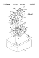
- FIG. 1 is a perspective view of a power distribution module according to the invention immediately prior to being mounted to a battery;
- FIG. 2 is a side view of the power distribution module of FIG. 1 mounted to a battery;
- FIG. 3 is a top view of the power distribution module of FIG. 1;
- FIG. 4 is an exploded view of the power distribution module of FIG. 1 with the cover removed;
- FIG. 5 is a top view of the battery connecting block of the invention power distribution module
- FIG. 6 is a top view of the fuse block portion of the invention power distribution module
- FIG. 7 is a front view of the fuse block of FIG. 6;
- FIG. 8 is a cross-sectional view taken along the line 8--8 of FIG. 7;
- FIG. 9 is a perspective view of a power distribution module cover according to the present invention.
- FIG. 10 is an exploded view of a portion of the invention power distribution module showing stages of the assembly of the fuse block and battery connecting block;
- FIG. 11 is a partial view of the fuse block of the invention power distribution module with load-side terminals being inserted therein;
- FIG. 12 is a perspective view of a one-piece molded fuse block and battery connecting block according to the present invention.
- FIG. 13 is a partial exploded view of a second embodiment of a battery connecting block according to the present invention.
- FIG. 14 is a perspective view of a power distribution module according to the present invention mounted to a battery having terminals extending from its side.
- a low-profile, battery-top power distribution module 10 is an essentially unitary, closed plastic structure which overlies the vehicle battery 70 and is held against or immediately adjacent the top surface of the battery by clamping bolts 72 and nuts 73.
- the module comprises a bottom shell which is divided into blocks 20 and 30 and a unitary top shell 40 which snaps into the bottom shell to enclose the internal components.
- the internal divisions of the bottom shell define a battery connecting block 20 and a fuse block 30 enclosing a bus bar terminal 25 and fuses 65.
- Mounting bolts 72 pass through holes formed in a plastic fuse block flange 39 and a harness guide flange 14 and are secured with nuts 73. While the module 10 appears to function as a battery hold-down clamp, it is not normally manufactured to have the structural strength required for this purpose. Battery hold-down is, therefore, performed by clamps 77 which act on bevelled base 76.
- the module 10 is essentially L-shaped as shown in FIG. 3 and covers only battery terminal 71; the opposite polarity terminal is left exposed for normal cable connection. Terminal 71, however, extends upwardly into assembly 12 in the bottom shell 20,30 for purposes to be described. The height of module 10 is only marginally greater than the height of terminal 71.
- Battery connecting block 20 comprises an electrically non-conductive case preferably made of an injection molded synthetic resin. As shown in FIGS. 4 and 5, battery connecting block 20 includes a terminal guide 11 extending along the rear of the block, a battery terminal connecting assembly 12 disposed at one end of terminal guide 11, and a harness guide channel 13 extending adjacent to post connecting assembly 12. Terminal guide 11 includes left and right side walls 11b, a front wall 11c, and an elongated bottom plate 11a which is of the same length as fuse block 30.
- Battery terminal connecting assembly 12 is closed at three sides, with left and right side walls 12b, a front wall 12c, and a bottom plate 12a extending from and contiguous with bottom plate 11a of terminal guide 11.
- Harness guide channel 13 includes left and right side walls 13b, and a bottom plate 13a extending from and contiguous with bottom plate 11a of terminal guide 11 to describe a T-shape. Harness guide channel 13 has a downwardly sloped harness outlet 13d from which a harness holder 13c extends vertically downward. Mounting flange 14 projects from right side wall 13b and has a hole formed therein.
- Battery terminal connecting assembly 12 is divided into a raised fuse mounting section 16 and a battery terminal section 15.
- Battery terminal section 15 is formed with a hole 17 in the bottom wall through which battery terminal 71 extends when power distribution module 10 is mounted on battery 70.
- a terminal connector positioning plate 18 with a hole 18a projects upward from bottom plate 12a adjacent to hole 17.
- a pair of terminal connector positioning flanges 19 are arranged on opposite sides of hole 17.
- Fuse mounting section 16 is provided with a pair of parallel, upwardly projecting fuse holding walls 35 and a pair of bolts 21 also extend upwardly near the ends of walls 35, with fuse seat nuts 22 threaded onto bolts 21.
- Battery connecting block 20 is formed with locking projections 23 on walls 11c, 12c, and 13b, which projections engage locking straps 45, 46 on cover 40 as hereinafter described.
- Side wall 12b is formed with a shallow, elongated cut-out 24a and a semi-circular cut-out 24b.
- Conductive metal bus bar 25 has a plurality of spaced tabs 27 extending from one side thereof, and a fuse connecting terminal 29 and a battery connecting terminal 28 extending from the opposite side thereof. Terminals 28 and 29 have holes 28a and 29a respectively formed therein. Fuse connecting terminal 29 has a step 29b located so that the terminal will extend over the raised fuse mounting area 16. Each of the tabs 27 has a locking hole 27a.
- fuse block 30 is a generally rectangular and also made of an electrically non-conductive synthetic resin, and has a plurality of fuse receptacles 31a formed therein along a forward end 30a. Each fuse receptacle 31a communicates with a load-side terminal cavity 31b and a tab cavity 31c formed along a rearward end 30b of fuse block 30.
- a horizontal wall 32 separates the load-side terminal cavities 31b from the tab cavities 31c, with the former located above the latter.
- resilient locking arms 33, 34 are molded to extend from fuse block 30 into cavities 31b, 31c respectively, and have locking projections 33a, 34a at their tips.
- a horizontal slit 36 extends longitudinally along fuse block 30, passing through the walls separating tab cavities 31c from one another and opening to the rearward end 30b of block 30.
- Bus bar 25 is inserted into fuse block 30 so that it is seated in slit 36 with tabs 27 extending forwardly into the lower portions of fuse receptacles 31a.
- Horizontal wall 32 extends from fuse block rearward end 30b, and the end portion of the wall adjacent battery connecting block 20 has a cut-out 37 formed therein so that the step 29b of power distributing terminal 25 clears wall 32.
- Locking projections 38a and 38b project from the left and right side walls 30c of fuse block 30.
- Mounting flange 39 is contiguous with a fuse block bottom wall 30d, projecting from the front side of the fuse block and having a pair of holes 39a.
- cover 40 includes as integral portions a main body 41, a battery terminal cover portion 42, and a fuse cover portion 43.
- Battery terminal cover portion 42 is made pivotal relative to body 41 by a living hinge, a narrow strip of material located between and formed integrally with the two portions and which is thinner than the structure to either side so as to form a flexible hinge line.
- Fuse cover portion 43 is made pivotal relative to main cover body 41 by living hinge 44a.
- Locking straps 45 extend from peripheral walls 41a, 41b and 41c of body 41 and have holes that engage locking projections 38b and 23 on fuse block 30 and battery connecting block 20 respectively.
- an inner wall 41d projects downward from the inner side of body 41 and extends adjacent battery post cover 42 to define a path along which harness wires 63 run between wall 32 and fuse block 30.
- Battery terminal cover portion 42 and fuse cover portion 43 are formed with locking straps 46a and 46b respectively to engage locking projections 23 and 38a and hold the covers in their closed positions.
- Battery terminal cover portion 42 has a front peripheral wall 42a which is formed with a shallow, elongated cut-out 48 to permit passage of a later described L-shaped terminal 68a, and a cable terminal cover 51b extends out from post cover 42 over cut-out 48.
- Cover 42 also has a shallow cut-out 47 which aligns with cut-out 24 in battery terminal connecting assembly side wall 12b when the cover is in its closed position, and a cable terminal cover 51a projects outward and downward from the cover.
- cable terminal cover 51b has a C-shaped cross section so as to surround terminal 68a when cover 42 is closed
- cable terminal cover 51a has an L-shaped cross section, as best seen in FIG. 14, so that it will not strike terminal 67a when cover 42 is moved between the open and closed positions.
- a semi-circular tab 49 also extends downwardly from side wall 42b to engage cut-out 24b in wall 12b when the cover is closed.
- power distribution module 10 is assembled by first inserting bus bar 25 into fuse block 30 from the rear side 30b, placing the bus bar in slit 36 beneath horizontal wall 32.
- Each of the tabs 27 projects into the corresponding cavity 31c and projections 34a of resilient locking arms 34 engage the corresponding locking hole 27a of each tab 27 to lock bus bar 25 in position.
- a battery terminal connector 50 is preliminarily positioned in battery terminal area 15 of battery terminal connecting assembly 12. As shown in FIGS. 4 and 10, battery terminal connector 50 comprises a cable terminal connection 52 and a C-shaped battery terminal clamp 53. Straps 54 extend from the free ends of clamp 53 and holes 54b pass through the straps. Cable terminal connection 52 holds an upwardly extending bolt 55.
- Battery terminal clamp 53 is first placed on bottom plate 12a such that terminal connector positioning plate 18 extends upward inside of clamp 53. Clamp 53 is then moved away from terminal connector positioning tab 18 until a flange 53a formed around the bottom of clamp 53 slides underneath terminal connector positioning flanges 19 and terminal positioning plate 18 is between straps 54. A bolt 56 is then inserted through holes 54b in straps 54 and hole 18a in terminal connector positioning plate 18, and a nut 57 is loosely threaded onto the bolt.
- a high current fuse 60 is next mounted in fuse mounting area 16 by placing holes in fuse tabs 61 over bolts 21a, 21b and pushing downward on the fuse until it is retained between walls 35 and on top of fuse seat nuts 22.
- High current fuse 60 is of the type commonly used in the automotive industry to protect a vehicle electrical system from short circuit conditions such as would be caused, for example, if an un-fused alternator cable were to contact an electrical ground.
- Battery connecting block 20 is then assembled to fuse block 30 so that bolt 55 of battery terminal connector 50 extends through hole 28a in battery connecting terminal 28 and bolt 21a of fuse mounting area 16 extends through hole 29a in fuse connecting terminal 29. Nuts 59, 58 are then threaded onto bolts 55, 21a respectively to secure terminals 28 and 29.
- load-side terminals 64 have locking holes 64a and are crimped to wires 63.
- Load-side terminals 64 are inserted into tab cavities 31b where locking holes 64a are engaged by locking projections 33a of locking arms 33 (as shown in FIG. 8).
- Wires 63 are routed along the upper surface of horizontal wall 32 and then outwardly through guide channel 13, with the bundled wires 63 forming a wiring harness 63a which is lashed to harness holder 13c by an elastic strap 66 or the equivalent (see FIG. 2).
- Conventionally known fuses 65 are inserted into fuse receptacles 31a from fuse block front side 30a, with one of two female fuse terminals of fuse 65 receiving tab 27 and the other receiving load-side terminal 64.
- the two blocks may be molded as an integral unit connected by a living hinge 80 as shown in FIG. 12. Hinge 80 is necessary because it is impractical to mold the two blocks in a co-planar unit. Rather, the unit is more advantageously molded with battery connecting block 20 and fuse block 30 at 90° to one another as seen in FIG. 12, thereby permitting the formation of cavities 31b and 31c. Blocks 20 and 30 are then bent about living hinge 80 during assembly of the power distribution module, placing them in a co-planar orientation with one another. Such one-piece construction is more economical to manufacture than two separate pieces and simplifies assembly of the power distribution module.
- cover 40 is placed over the battery connecting block 10 and fuse block 30, and locking straps 45 engage locking projections 23 and 38b to firmly connect cover body 41 to blocks 20 and 30.
- Terminal cover 42 and fuse cover 43 are locked in their closed positions by locking straps 46a and 46b respectively in a similar manner.
- Power distribution module 10 is placed onto battery 70 with terminal cover 42 open, as shown in FIG. 2, so that battery terminal 71 extends upwardly through hole 17 into the battery terminal connecting assembly 12 to be encircled by battery terminal clamp 53 which has been preliminarily mounted in battery terminal area 15. Bolt 56 and nut 57 are now tightened to securely fasten clamp 53 to battery terminal 71.
- power distribution module 10 is secured to the vehicle body by mounting bolts 72.
- the lower ends of mounting bolts 72 engage battery hold-down means 77 which secure battery 70 to a battery mounting platform 76 attached to the vehicle body, and the upper ends of the mounting bolts pass through holes formed in fuse block flange 39 and harness guide flange 14 and are secured with nuts 73.
- Nut 59 is disconnected from battery terminal bolt 55 and a starter cable terminal 67a is placed over battery terminal connector 50 and nut 59 is again threaded onto bolt 55 and tightened securely.
- Terminal 67a is connected with a starter cable 67b which supplies battery power to a conventional starter motor (not shown).
- nut 58b is removed from bolt 21b and alternator cable terminal 68a is placed over bolt 21b on top of fuse terminal 61 and nut 58b is retightened.
- Terminal 68a is connected to an alternator cable 68b to allow current from an alternator (not shown) to charge battery 70 and be supplied to bus bar 25.
- cable terminals 67a and 68a extend outwardly from battery terminal connecting assembly 12, with starter cable terminal 67b passing through cut-out 24a in left side wall 12b and alternator cable terminal 68a passing over the top edge of front wall 12c.
- cable terminal covers 51a and 51b shield cable terminals 67a and 68a respectively to protect the terminals from moisture and dirt, and to prevent accidental contact with the terminals that could cause electrical shorting.
- power distribution module 10 extends above the top of battery terminal 71 by an amount slightly greater than the thickness of the top surface of cover 42.
- FIG. 13 illustrates a second embodiment of a battery terminal connecting assembly 12' differing from the above-described first embodiment in that fuse mounting section 16' is not raised with respect to battery terminal section 15, but rather the two sections are co-planar.
- a battery terminal connector 50' is of the same basic construction as battery terminal connector 50 of the first embodiment except that a fuse connecting jumper 52b extends laterally from cable terminal connection 52' to connect with bolt 21a. Because fuse connecting jumper 52b provides electrical connection between fuse 60 and battery terminal connector 50', bus bar 25' need be connected with battery terminal connecting assembly 12' only by means of battery connecting terminal 28'.
- fuse connecting jumper 52b with battery terminal connector 50' facilitates assembly of the battery terminal connecting assembly 12' to battery 70 and also simplifies the construction of bus bar 25' by eliminating the stepped fuse connecting terminal 29 present in the first embodiment.
- FIG. 14 illustrates a third embodiment of a power distribution module 10' according to the present invention for use on a battery 70' having a side-mounted battery terminal 71'.
- Power distribution module 10' is substantially identical to the module described above, except that contact with side battery terminal 71' is made by a battery terminal connector 50" extending out of battery terminal area 15' through a slot 82 formed in front wall 12c. Battery terminal connector 50" bends downward approximately 90° to engage battery terminal 71'.
- Battery terminal cover 42' has a battery terminal cover extension 51c to cover battery terminal 71' and battery terminal connector 50" when cover 42' is in the closed position.
Abstract
An electrical power distribution module for use with an automotive vehicle electrical system is adapted to be mounted on the top surface of a standard automotive lead-acid storage battery and connect with a battery terminal extending therefrom. The power distribution module includes a battery post connecting assembly for housing a terminal connector for making electrical connections with the battery terminal and alternator and starter cables, a fuse block for receiving a plurality of fuses associated with separate vehicle electrical circuits, and a harness guide channel for routing a plurality of wires which connect the fuses with their associated circuits. The power distribution module is mounted to lay flat on top of the battery's upper surface with the battery terminal extending upwardly into the module to be engaged by the battery terminal connector. The module does not extend substantially above the highest point of the battery terminal, nor does it extend laterally substantially outside of the battery perimeter. A cover is attached to the power distribution module and has hinged sections which may be opened to provide access to the battery terminal connector and the fuse receptacles.
Description
The present invention relates to electrical power distribution module for use in automotive vehicles, and more particularly to a power distribution module which is mounted on top of a vehicle battery.
Automotive vehicle electrical systems typically operate on direct current supplied by an engine-driven alternator in combination with a lead-acid storage battery. The alternator and the battery are connected to various circuits for the different electrically powered components of the vehicle. Conventionally, the circuits are provided with protection from over-current conditions by fuses, at least some of which are located in a fuse box mounted in the vehicle engine compartment. To reduce the amount and complexity of electrical wiring in the engine compartment, the fuse box is preferably placed close to the battery.
Several prior art fuse boxes are mounted directly to the battery. One example of such a fuse box is disclosed in Japanese Utility Model Preliminary Publication No. 63-182048. The fuse box houses a plurality of fuses which plug into a bus bar which extends from the box and bent is to form a strap which is mechanically and electrically connected to the battery terminal or post. An additional mechanical connection with the battery is provided by a mounting arm extending from the fuse box and secured to one of the battery solution inlet caps. Most of the weight of the fuse box is supported by the battery post, giving rise to the possibility that the battery post may be overstressed and battery fluids may leak from the battery around the post.
A second battery mounted fuse box is taught by Japanese Utility Model Preliminary Publication No. 64-19261 in which the battery is formed with a notch in its upper surface and a fuse box is provided with locking arms which engage the notch to support the fuse box in a position alongside the battery. A connecting strap extends between the battery post and the bus bar housed inside the fuse box, but mechanical loads and stresses are transferred to the body of the battery via the locking arms rather than directly to the battery post. This construction reduces the likelihood of leakage around the battery post, but it does not lend itself to general application since a specially designated battery having an appropriately shaped notch is required.
Both of the above-described fuse boxes are mounted adjacent the side surface of the battery and thus require that additional lateral space for the box be provided when it is installed in the vehicle. In some automotive applications, particularly in small vehicles, lateral space in the vehicle engine compartment is at a great premium and there may not be sufficient room for such a side battery mounting. Further, even if the battery installation does permit room for a side-mounted fuse module, the location of the battery within the engine compartment may force the fuse box to be positioned in a place which is difficult to reach if it is necessary to replace fuses or perform other maintenance involving the fuse box.
According to the present invention, a battery-mounted, fuse-protected electrical power distribution module is provided for use with an automotive vehicle battery having a substantially horizontal top surface. The power distribution module includes a battery terminal connector for making electrical contact with a battery terminal and a plurality of fuse receptacles electrically connected with the battery terminal. The power distribution module is mounted to the battery so as to be positioned essentially against and over the battery top surface and is low-profile so as to extend only marginally above the battery terminals. The module is compatible with standard battery designs, imposes no adverse load on the battery terminals, provides access to automotive fuses, and makes efficient use of space in the battery-mounting area.
According to another feature of the invention, the power distribution module is designed to fit substantially within the perimeter of the battery top surface, and when mounted to a battery having an upwardly projecting battery terminal to extend only slightly higher than the highest point of the battery terminal. This results in a very compact mounting.
According to a further feature of the invention, a bus bar electrically connecting the battery terminal connector to the fuse receptacles lies in a substantially horizontal plane in close proximity to the battery top surface. This is important in achieving the low profile design of the power distribution module as mentioned above.
According to still another feature of the invention, the power distribution module includes means for electrically connecting a starter cable with the battery terminal connector and an alternator cable with the bus bar. By integrating into the power distribution module the connections for these other electrical system components, the power distribution module is easily installed in a vehicle.
According to yet another feature of the invention, the power distribution module includes means for mounting a high-current fuse between the alternator cable and the bus bar, thereby providing a convenient and protected installation for the fuse which protects the vehicle electrical system against short circuit conditions.
According to yet another feature of the invention, the fuse receptacles which make up the fuse module portion of the power distribution module are arranged in a horizontal row substantially parallel with and in close proximity to the battery top surface, and are oriented such that fuses are inserted therein in a horizontal direction.
According to a still further feature of the invention, the power distribution module includes a wire harness guide channel through which are routed a plurality of wires connected with the fuse receptacles. The guide channel routes these wires over the top surface of the battery and keeps them in a compact, protected bundle.
According to another feature of the invention, the power distribution module further includes a cover having at least two separately openable hinged portions, one portion opening to allow access to the battery terminal connector and another opening to allow access to the fuse receptacles. The cover thereby provides substantial protection against harmful contaminants and against shorting, while allowing convenient access to the terminal and fuse receptacles when necessary for maintenance.
According to yet another feature of the invention, the electrical power distribution module when mounted to the battery substantially encloses the battery terminal, thus protecting the terminal from corrosive materials as well as from contact with other objects which might cause electrical shorting.
FIG. 1 is a perspective view of a power distribution module according to the invention immediately prior to being mounted to a battery;
FIG. 2 is a side view of the power distribution module of FIG. 1 mounted to a battery;
FIG. 3 is a top view of the power distribution module of FIG. 1;
FIG. 4 is an exploded view of the power distribution module of FIG. 1 with the cover removed;
FIG. 5 is a top view of the battery connecting block of the invention power distribution module;
FIG. 6 is a top view of the fuse block portion of the invention power distribution module;
FIG. 7 is a front view of the fuse block of FIG. 6;
FIG. 8 is a cross-sectional view taken along the line 8--8 of FIG. 7;
FIG. 9 is a perspective view of a power distribution module cover according to the present invention;
FIG. 10 is an exploded view of a portion of the invention power distribution module showing stages of the assembly of the fuse block and battery connecting block;
FIG. 11 is a partial view of the fuse block of the invention power distribution module with load-side terminals being inserted therein;
FIG. 12 is a perspective view of a one-piece molded fuse block and battery connecting block according to the present invention;
FIG. 13 is a partial exploded view of a second embodiment of a battery connecting block according to the present invention; and
FIG. 14 is a perspective view of a power distribution module according to the present invention mounted to a battery having terminals extending from its side.
Referring to FIGS. 1-3, a low-profile, battery-top power distribution module 10 is an essentially unitary, closed plastic structure which overlies the vehicle battery 70 and is held against or immediately adjacent the top surface of the battery by clamping bolts 72 and nuts 73. The module comprises a bottom shell which is divided into blocks 20 and 30 and a unitary top shell 40 which snaps into the bottom shell to enclose the internal components. The internal divisions of the bottom shell define a battery connecting block 20 and a fuse block 30 enclosing a bus bar terminal 25 and fuses 65. Mounting bolts 72 pass through holes formed in a plastic fuse block flange 39 and a harness guide flange 14 and are secured with nuts 73. While the module 10 appears to function as a battery hold-down clamp, it is not normally manufactured to have the structural strength required for this purpose. Battery hold-down is, therefore, performed by clamps 77 which act on bevelled base 76.
The module 10 is essentially L-shaped as shown in FIG. 3 and covers only battery terminal 71; the opposite polarity terminal is left exposed for normal cable connection. Terminal 71, however, extends upwardly into assembly 12 in the bottom shell 20,30 for purposes to be described. The height of module 10 is only marginally greater than the height of terminal 71.
Battery terminal connecting assembly 12 is closed at three sides, with left and right side walls 12b, a front wall 12c, and a bottom plate 12a extending from and contiguous with bottom plate 11a of terminal guide 11.
Battery terminal connecting assembly 12 is divided into a raised fuse mounting section 16 and a battery terminal section 15. Battery terminal section 15 is formed with a hole 17 in the bottom wall through which battery terminal 71 extends when power distribution module 10 is mounted on battery 70. A terminal connector positioning plate 18 with a hole 18a projects upward from bottom plate 12a adjacent to hole 17. A pair of terminal connector positioning flanges 19 are arranged on opposite sides of hole 17. Fuse mounting section 16 is provided with a pair of parallel, upwardly projecting fuse holding walls 35 and a pair of bolts 21 also extend upwardly near the ends of walls 35, with fuse seat nuts 22 threaded onto bolts 21. Battery connecting block 20 is formed with locking projections 23 on walls 11c, 12c, and 13b, which projections engage locking straps 45, 46 on cover 40 as hereinafter described. Side wall 12b is formed with a shallow, elongated cut-out 24a and a semi-circular cut-out 24b.
Conductive metal bus bar 25 has a plurality of spaced tabs 27 extending from one side thereof, and a fuse connecting terminal 29 and a battery connecting terminal 28 extending from the opposite side thereof. Terminals 28 and 29 have holes 28a and 29a respectively formed therein. Fuse connecting terminal 29 has a step 29b located so that the terminal will extend over the raised fuse mounting area 16. Each of the tabs 27 has a locking hole 27a.
Referring now to FIGS. 6-8, fuse block 30 is a generally rectangular and also made of an electrically non-conductive synthetic resin, and has a plurality of fuse receptacles 31a formed therein along a forward end 30a. Each fuse receptacle 31a communicates with a load-side terminal cavity 31b and a tab cavity 31c formed along a rearward end 30b of fuse block 30. A horizontal wall 32 separates the load-side terminal cavities 31b from the tab cavities 31c, with the former located above the latter. As best seen in FIG. 8, resilient locking arms 33, 34 are molded to extend from fuse block 30 into cavities 31b, 31c respectively, and have locking projections 33a, 34a at their tips. A horizontal slit 36 extends longitudinally along fuse block 30, passing through the walls separating tab cavities 31c from one another and opening to the rearward end 30b of block 30. Bus bar 25 is inserted into fuse block 30 so that it is seated in slit 36 with tabs 27 extending forwardly into the lower portions of fuse receptacles 31a.
As shown in FIGS. 1, 2 and 9, cover 40 includes as integral portions a main body 41, a battery terminal cover portion 42, and a fuse cover portion 43. Battery terminal cover portion 42 is made pivotal relative to body 41 by a living hinge, a narrow strip of material located between and formed integrally with the two portions and which is thinner than the structure to either side so as to form a flexible hinge line. Fuse cover portion 43 is made pivotal relative to main cover body 41 by living hinge 44a. When cover 40 is fitted over battery connecting block 20 and fuse block 30, body 41 is fixed and covers harness guide channel 13 and most of fuse block 30. Hinged cover portion 43 provides access to the ends of the fuses for placement and replacement purposes. Cover portion 42 provides access to the battery terminal clamp 53 and the main fuse 60. Locking straps 45 extend from peripheral walls 41a, 41b and 41c of body 41 and have holes that engage locking projections 38b and 23 on fuse block 30 and battery connecting block 20 respectively. As best seen in FIG. 2, an inner wall 41d projects downward from the inner side of body 41 and extends adjacent battery post cover 42 to define a path along which harness wires 63 run between wall 32 and fuse block 30.
Battery terminal cover portion 42 and fuse cover portion 43 are formed with locking straps 46a and 46b respectively to engage locking projections 23 and 38a and hold the covers in their closed positions. Battery terminal cover portion 42 has a front peripheral wall 42a which is formed with a shallow, elongated cut-out 48 to permit passage of a later described L-shaped terminal 68a, and a cable terminal cover 51b extends out from post cover 42 over cut-out 48. Cover 42 also has a shallow cut-out 47 which aligns with cut-out 24 in battery terminal connecting assembly side wall 12b when the cover is in its closed position, and a cable terminal cover 51a projects outward and downward from the cover. While cable terminal cover 51b has a C-shaped cross section so as to surround terminal 68a when cover 42 is closed, cable terminal cover 51a has an L-shaped cross section, as best seen in FIG. 14, so that it will not strike terminal 67a when cover 42 is moved between the open and closed positions. A semi-circular tab 49 also extends downwardly from side wall 42b to engage cut-out 24b in wall 12b when the cover is closed.
As shown in FIGS. 10 and 11, power distribution module 10 is assembled by first inserting bus bar 25 into fuse block 30 from the rear side 30b, placing the bus bar in slit 36 beneath horizontal wall 32. Each of the tabs 27 projects into the corresponding cavity 31c and projections 34a of resilient locking arms 34 engage the corresponding locking hole 27a of each tab 27 to lock bus bar 25 in position.
A battery terminal connector 50 is preliminarily positioned in battery terminal area 15 of battery terminal connecting assembly 12. As shown in FIGS. 4 and 10, battery terminal connector 50 comprises a cable terminal connection 52 and a C-shaped battery terminal clamp 53. Straps 54 extend from the free ends of clamp 53 and holes 54b pass through the straps. Cable terminal connection 52 holds an upwardly extending bolt 55.
A high current fuse 60 is next mounted in fuse mounting area 16 by placing holes in fuse tabs 61 over bolts 21a, 21b and pushing downward on the fuse until it is retained between walls 35 and on top of fuse seat nuts 22. High current fuse 60 is of the type commonly used in the automotive industry to protect a vehicle electrical system from short circuit conditions such as would be caused, for example, if an un-fused alternator cable were to contact an electrical ground. Battery connecting block 20 is then assembled to fuse block 30 so that bolt 55 of battery terminal connector 50 extends through hole 28a in battery connecting terminal 28 and bolt 21a of fuse mounting area 16 extends through hole 29a in fuse connecting terminal 29. Nuts 59, 58 are then threaded onto bolts 55, 21a respectively to secure terminals 28 and 29.
As shown in FIG. 11, load-side terminals 64 have locking holes 64a and are crimped to wires 63. Load-side terminals 64 are inserted into tab cavities 31b where locking holes 64a are engaged by locking projections 33a of locking arms 33 (as shown in FIG. 8). Wires 63 are routed along the upper surface of horizontal wall 32 and then outwardly through guide channel 13, with the bundled wires 63 forming a wiring harness 63a which is lashed to harness holder 13c by an elastic strap 66 or the equivalent (see FIG. 2).
Conventionally known fuses 65 are inserted into fuse receptacles 31a from fuse block front side 30a, with one of two female fuse terminals of fuse 65 receiving tab 27 and the other receiving load-side terminal 64.
As an alternative to forming battery connecting block 20 and fuse block 30 as two separate pieces, the two blocks may be molded as an integral unit connected by a living hinge 80 as shown in FIG. 12. Hinge 80 is necessary because it is impractical to mold the two blocks in a co-planar unit. Rather, the unit is more advantageously molded with battery connecting block 20 and fuse block 30 at 90° to one another as seen in FIG. 12, thereby permitting the formation of cavities 31b and 31c. Blocks 20 and 30 are then bent about living hinge 80 during assembly of the power distribution module, placing them in a co-planar orientation with one another. Such one-piece construction is more economical to manufacture than two separate pieces and simplifies assembly of the power distribution module.
Referring again to FIG. 2, cover 40 is placed over the battery connecting block 10 and fuse block 30, and locking straps 45 engage locking projections 23 and 38b to firmly connect cover body 41 to blocks 20 and 30. Terminal cover 42 and fuse cover 43 are locked in their closed positions by locking straps 46a and 46b respectively in a similar manner.
As shown in FIG. 1, power distribution module 10 is secured to the vehicle body by mounting bolts 72. The lower ends of mounting bolts 72 engage battery hold-down means 77 which secure battery 70 to a battery mounting platform 76 attached to the vehicle body, and the upper ends of the mounting bolts pass through holes formed in fuse block flange 39 and harness guide flange 14 and are secured with nuts 73.
When fastened to power distribution module 10 as described above, cable terminals 67a and 68a extend outwardly from battery terminal connecting assembly 12, with starter cable terminal 67b passing through cut-out 24a in left side wall 12b and alternator cable terminal 68a passing over the top edge of front wall 12c. When terminal cover 42 is closed over battery connecting block 10 cable terminal covers 51a and 51b shield cable terminals 67a and 68a respectively to protect the terminals from moisture and dirt, and to prevent accidental contact with the terminals that could cause electrical shorting. When battery terminal cover 42 is closed, power distribution module 10 extends above the top of battery terminal 71 by an amount slightly greater than the thickness of the top surface of cover 42.
FIG. 13 illustrates a second embodiment of a battery terminal connecting assembly 12' differing from the above-described first embodiment in that fuse mounting section 16' is not raised with respect to battery terminal section 15, but rather the two sections are co-planar. A battery terminal connector 50' is of the same basic construction as battery terminal connector 50 of the first embodiment except that a fuse connecting jumper 52b extends laterally from cable terminal connection 52' to connect with bolt 21a. Because fuse connecting jumper 52b provides electrical connection between fuse 60 and battery terminal connector 50', bus bar 25' need be connected with battery terminal connecting assembly 12' only by means of battery connecting terminal 28'.
The integration of fuse connecting jumper 52b with battery terminal connector 50' facilitates assembly of the battery terminal connecting assembly 12' to battery 70 and also simplifies the construction of bus bar 25' by eliminating the stepped fuse connecting terminal 29 present in the first embodiment.
FIG. 14 illustrates a third embodiment of a power distribution module 10' according to the present invention for use on a battery 70' having a side-mounted battery terminal 71'. Power distribution module 10' is substantially identical to the module described above, except that contact with side battery terminal 71' is made by a battery terminal connector 50" extending out of battery terminal area 15' through a slot 82 formed in front wall 12c. Battery terminal connector 50" bends downward approximately 90° to engage battery terminal 71'. Battery terminal cover 42' has a battery terminal cover extension 51c to cover battery terminal 71' and battery terminal connector 50" when cover 42' is in the closed position.
Whereas the preferred embodiments of the invention have been illustrated and described in detail, it will be apparent that various changes may be made in the disclosed embodiments without departing from the scope or spirit of the invention.
Claims (16)
1. An electrical power distribution module for mounting to a vehicle battery having a substantially horizontal top surface and a battery terminal projecting from the top surface, the power distribution unit comprising:
a battery terminal connector for making electrical contact with the battery terminal and a plurality of fuse receptacles electrically connected with the battery terminal connector by a bus bar, characterized in that the power distribution module is adapted to be mounted in overlying relation to the battery top surface.
2. A power distribution module according to claim 1 characterized in that when mounted to the battery the power distribution module lies essentially within the lateral boundaries of the battery top surface.
3. A power distribution module according to claim 1 wherein the bus bar lies in a substantially horizontal plane.
4. A power distribution module according to claim 1 further including means for electrically connecting a starter cable with the battery terminal connector and an alternator cable with the bus bar.
5. A power distribution module according to claim 4 further including means for mounting a fuse between the alternator cable and the bus bar.
6. A power distribution module according to claim 1 wherein the fuse receptacles lie in a horizontal row substantially parallel with the battery top surface and are oriented such that fuses may be inserted horizontally therein.
7. A power distribution module according to claim 1 further including a wire harness guide channel for routing a plurality of wires connected with the fuse receptacles over the battery top surface.
8. A power distribution module according to claim 1 further including a cover having at least first and second separately openable hinged portions, the first hinged portion providing access to the battery terminal connector and the second hinged portion providing access to the fuse receptacles.
9. An electrical power distribution module for mounting to an automotive vehicle battery having a battery terminal with portions projecting therefrom, the power distribution module comprising:
a battery terminal connector for making electrical contact with the battery terminal and a plurality of fuse receptacles electrically connected to the battery terminal connector by a bus bar, characterized in that the power distribution module when mounted to the battery encloses the portions of the battery terminal projecting from the battery.
10. An electrical power distribution module adapted to be mounted above an automotive vehicle battery having a battery terminal projecting upward from a substantially horizontal top surface of the battery, the power distribution module comprising:
a battery connecting block positioned over the battery terminal and having a battery terminal connector for making electrical connection with the battery terminal, means for electrically connecting a starter cable and an alternator cable to the power distribution module, and fuse mounting means for mounting a main fuse in electrical connection between the alternator cable and the power distribution module;
a fuse block adapted to lie in a substantially horizontal plane above the battery top surface and having a plurality of horizontally oriented fuse receptacles and a bus bar electrically connecting the fuse receptacles with the battery terminal connector, the bus bar lying in a substantially horizontal plane;
a wire harness guide channel for routing a plurality of wires connected with the fuse receptacles over the battery top surface; and
a cover for covering the battery connecting block, the fuse block, and the wire harness guide channel and having at least first and second separately openable hinged portions, the first hinged portion openable to allow access to the battery terminal connector and the second hinged portion openable to allow access to the fuse receptacles.
11. A battery-mounted, fuse-protected, automotive power distribution module comprising:
a housing of electrically non-conductive material having respective internal spaces for a battery terminal connector, a distribution bus bar and a plurality of fuses;
a battery terminal connector in the battery terminal connector space;
a bus bar disposed in the bus bar space and electrically connected to the battery terminal connector; and
means for mounting the module in overlying relation to an automotive battery with a terminal of the battery extending upwardly into the battery terminal connector.
12. A battery-mounted, fuse-protected automotive power distribution module as defined in claim 11 wherein said housing includes a first cover portion for providing access to the battery terminal connector space.
13. A battery-mounted, fuse-protected automotive power distribution module as defined in claim 11 wherein said housing includes a second cover portion for providing access to said fuse space.
14. A battery-mounted, fuse-protected automotive power distribution module as defined in claim 11 further including a plurality of fuses mounted within said fuse space and means for electrically connecting said fuses to said distribution bus bar.
15. A battery-mounted, fuse-protected automotive power distribution module as defined in claim 11 wherein said means for mounting the module comprises a plurality of threaded clamping rods extending in mutually parallel relation through a portion of said housing, and threaded nuts engaging the end portions of said rods.
16. A power distribution module according to claim 1 wherein the battery terminal connector, the fuse receptacles, and the bus bar do not project above a highest point of the battery terminal.
Priority Applications (1)
| Application Number | Priority Date | Filing Date | Title |
|---|---|---|---|
| US08/550,367 US5643693A (en) | 1995-10-30 | 1995-10-30 | Battery-mounted power distribution module |
Applications Claiming Priority (1)
| Application Number | Priority Date | Filing Date | Title |
|---|---|---|---|
| US08/550,367 US5643693A (en) | 1995-10-30 | 1995-10-30 | Battery-mounted power distribution module |
Publications (1)
| Publication Number | Publication Date |
|---|---|
| US5643693A true US5643693A (en) | 1997-07-01 |
Family
ID=24196875
Family Applications (1)
| Application Number | Title | Priority Date | Filing Date |
|---|---|---|---|
| US08/550,367 Expired - Lifetime US5643693A (en) | 1995-10-30 | 1995-10-30 | Battery-mounted power distribution module |
Country Status (1)
| Country | Link |
|---|---|
| US (1) | US5643693A (en) |
Cited By (127)
| Publication number | Priority date | Publication date | Assignee | Title |
|---|---|---|---|---|
| GB2326287A (en) * | 1997-06-09 | 1998-12-16 | Delphi Automotive Systems Gmbh | Fuse assembly |
| GB2330253A (en) * | 1997-10-13 | 1999-04-14 | Toyota Motor Co Ltd | A molded resin connecting plate for electric vehicle batteries with integral bus bars and voltage-detection terminals |
| GB2330252A (en) * | 1997-10-13 | 1999-04-14 | Toyota Motor Co Ltd | A molded resin connecting plate for electric vehicle batteries with integral bus bars and voltage-detection terminals |
| GB2330251A (en) * | 1997-10-13 | 1999-04-14 | Toyota Motor Co Ltd | A molded resin connecting plate for electric vehicle batteries with integral bus bars and voltage-detection terminals |
| US5897392A (en) * | 1997-03-26 | 1999-04-27 | Yazaki Corporation | Wire retaining clip |
| US6010804A (en) * | 1998-04-30 | 2000-01-04 | Barksdale; Henry R. | Protective cover and connection device for batteries |
| US6010375A (en) * | 1997-06-30 | 2000-01-04 | Sumitomo Wiring Systems, Ltd. | Connection construction for a battery and an electrical connection box |
| US6062899A (en) * | 1998-09-15 | 2000-05-16 | Chrysler Corporation | Digital verification of battery cable connection to power distribution module |
| DE19906000A1 (en) * | 1999-02-15 | 2000-08-17 | Volkswagen Ag | Power connector strip for motor vehicles has generator part contg. fuse, starter part contg. external starter point; starter part engages generator part via tooth arrangement and is embedded |
| EP1054461A2 (en) * | 1999-05-18 | 2000-11-22 | Yazaki Corporation | Battery connection plate and a manufacturing method therefor |
| US6215636B1 (en) * | 1997-03-24 | 2001-04-10 | Siemens Automotive, S.A. | Device for supplying electric power to several parallel-fed circuits, and method for making same |
| US6232013B1 (en) * | 1997-11-26 | 2001-05-15 | Lucent Technologies Inc. | Droppable battery packs |
| US6294978B1 (en) * | 1998-03-16 | 2001-09-25 | Yazaki Corporation | High-current fuse for vehicles |
| US6346011B1 (en) * | 1998-10-09 | 2002-02-12 | Yazaki Corporation | Battery-connecting plate, method of producing same and wire protector |
| US6396380B1 (en) * | 1996-04-19 | 2002-05-28 | Trw Automotive Electronics & Components Gmbh & Co. Kg | Electrical fuse box for motor vehicles |
| EP1239506A2 (en) * | 2001-03-07 | 2002-09-11 | Yazaki Corporation | Protective cover and fuse box |
| US6456188B1 (en) * | 1999-11-25 | 2002-09-24 | Yazaki Corporation | Connecting structure of a fuse link and external terminals |
| US6494279B1 (en) * | 1998-06-11 | 2002-12-17 | Gnb Technologies, Inc. | Battery enclosure system for motive power in hazardous service environments |
| US20020191385A1 (en) * | 2001-06-13 | 2002-12-19 | Honda Giken Kogyo Kabushiki Kaisha | Automotive equipment mounting structure |
| ES2178919A1 (en) * | 2000-04-24 | 2003-01-01 | Cables Perti Sa | Procedure for connecting cables and fuse box to a battery |
| US6512443B1 (en) * | 1999-05-18 | 2003-01-28 | Yazaki Corporation | Large current fuse for direct coupling to power source |
| US6545861B1 (en) * | 2001-11-20 | 2003-04-08 | Fci Americas Technology, Inc. | High voltage distribution box with pre-molded lead frame |
| EP1310972A1 (en) * | 2001-11-09 | 2003-05-14 | Meccanotecnica Codognese S.p.A. | Fuse box for vehicles |
| US20030090358A1 (en) * | 2001-11-14 | 2003-05-15 | Yazaki Corporation | Power distributing box and power-device module |
| US6642633B1 (en) | 2001-06-27 | 2003-11-04 | Yazaki North America, Inc. | Power management assembly |
| US6650024B2 (en) * | 2000-08-02 | 2003-11-18 | Autonetworks Technologies, Ltd | Vehicle power distributor and method of producing the same |
| EP1369305A2 (en) * | 2002-06-04 | 2003-12-10 | Alcoa Fujikura Ltd. | Power management and distribution assembly mountable on a battery |
| US20040018417A1 (en) * | 2002-07-23 | 2004-01-29 | Stack Thomas James | Battery fuse bus bar assembly |
| US6696914B2 (en) * | 1999-12-29 | 2004-02-24 | Robert Bosch Gmbh | Electrical fuse for rotary current generator with rectifier |
| US6759938B2 (en) * | 2001-04-27 | 2004-07-06 | Yazaki Corporation | Fuse link assembly and layout method therefor |
| US20040132335A1 (en) * | 2002-03-12 | 2004-07-08 | Sumitomo Wiring Systems, Ltd. | Battery connecting member and method of mounting it to a battery |
| US6824430B2 (en) | 2002-10-02 | 2004-11-30 | Yazaki Corporation | Fusible link unit |
| US20050116806A1 (en) * | 2003-10-31 | 2005-06-02 | Yazaki Corporation | Fuse unit |
| US20050116807A1 (en) * | 2003-12-02 | 2005-06-02 | Sumitomo Wiring Systems, Ltd. | Electrical junction box |
| US20050134423A1 (en) * | 2003-12-20 | 2005-06-23 | Lear Corporation | Mounting Device for Laminated Fuses |
| US20050190519A1 (en) * | 2003-11-26 | 2005-09-01 | Brown William P. | Vehicle electrical protection device and system employing same |
| US20050285709A1 (en) * | 2003-12-24 | 2005-12-29 | Norio Matsumura | Fusible link unit |
| US20050285223A1 (en) * | 2003-07-16 | 2005-12-29 | Leigh Stan E | Fuse structure |
| US20060003627A1 (en) * | 2004-07-01 | 2006-01-05 | Erik Freitag | Fused battery terminal connector |
| EP1621410A2 (en) * | 2004-07-27 | 2006-02-01 | Paccar Inc. | Electrical power unit and power distribution center therefor for vehicles |
| US20060036362A1 (en) * | 2004-08-04 | 2006-02-16 | Yazaki Corporation, | High-tension connector box |
| US20070063809A1 (en) * | 2005-09-21 | 2007-03-22 | Yazaki Corporation | Fusible link |
| WO2007101596A1 (en) * | 2006-03-03 | 2007-09-13 | Auto Kabel Managementgesellschaft Mbh | Arrangement for power distribution and contact-making therewith and protection of the outgoing lines |
| US20070241858A1 (en) * | 2004-02-19 | 2007-10-18 | Autonetworks Technologies, Ltd. | Fuse Module |
| US20070241857A1 (en) * | 2006-04-18 | 2007-10-18 | Sumitomo Wiring Systems, Ltd. | Fusible link unit accommodated in in-vehicle electrical connection box |
| EP1850407A1 (en) * | 2005-02-16 | 2007-10-31 | Toyota Jidosha Kabushiki Kaisha | Battery pack and automobile |
| US20080030295A1 (en) * | 2006-08-04 | 2008-02-07 | Yusuke Matsumoto | Fusible Link Unit |
| US20080042795A1 (en) * | 2006-05-24 | 2008-02-21 | Lisa Draxlmaier Gmbh | Fuse Unit |
| WO2008035874A1 (en) * | 2006-09-18 | 2008-03-27 | Lg Chem, Ltd. | Equal distribution-typed bus bar, and middle or large-sized battery pack employed with the same |
| US20080153325A1 (en) * | 2006-09-08 | 2008-06-26 | Boileau Daniel E | Modular power distribution center |
| US20080268671A1 (en) * | 2007-04-24 | 2008-10-30 | Littelfuse, Inc. | Fuse card system for automotive circuit protection |
| US20090006815A1 (en) * | 2007-06-20 | 2009-01-01 | I Squared Llc | System and method for interfacing devices |
| US20090045906A1 (en) * | 2007-08-13 | 2009-02-19 | Littelfuse, Inc. | Moderately hazardous environment fuse |
| US20090053588A1 (en) * | 2007-08-24 | 2009-02-26 | Panasonic Ev Energy Co., Ltd. | Battery pack |
| US20090061291A1 (en) * | 2007-09-03 | 2009-03-05 | Norihiro Ohashi | Protection cover attachment structure of battery-mounted fusible link unit |
| US20090108982A1 (en) * | 2007-10-31 | 2009-04-30 | Yazaki Corporation | Fusible link unit |
| US20090155675A1 (en) * | 2006-08-29 | 2009-06-18 | Johnson Controls - Saft Advanced Power Solutions Llc | Battery module |
| US20090251200A1 (en) * | 2008-04-02 | 2009-10-08 | Littlefuse, Inc. | Master fuse module |
| US20090269951A1 (en) * | 2008-04-23 | 2009-10-29 | Littelfuse, Inc. | Flexible power distribution module |
| US7663466B1 (en) * | 2007-09-21 | 2010-02-16 | Yazaki North America, Inc. | Corner-mounted battery fuse |
| US20100047682A1 (en) * | 2007-03-01 | 2010-02-25 | Johnson Controls - SAFT Advanced Power Solutions, LLC | Battery system and thermal management system therefor |
| US20100060407A1 (en) * | 2008-09-05 | 2010-03-11 | Yazaki Corporation | Complex type fusible link, fuse box, and manufacturing method thereof |
| US20100092849A1 (en) * | 2007-03-01 | 2010-04-15 | Johnson Controls-Saft Advanced Power Solutions Llc | Battery module |
| US7728704B2 (en) | 2007-06-07 | 2010-06-01 | Trombetta, Llc | Method for reducing continuous charge |
| WO2010081086A1 (en) * | 2009-01-12 | 2010-07-15 | A123 Systems, Inc. | Fuse for battery cells |
| US20100255351A1 (en) * | 2009-01-07 | 2010-10-07 | A123 Systems, Inc. | Fuse for battery cells |
| US20100261377A1 (en) * | 2006-08-31 | 2010-10-14 | Lisa Draxlmaier Gmbh | Tolerance-compensating current distribution board |
| US20110045343A1 (en) * | 2009-08-20 | 2011-02-24 | Roland Barkoczi | High voltage battery system having modular high voltage battery interface with integrated connector and fuse |
| EP2296206A1 (en) * | 2009-09-11 | 2011-03-16 | MAGNA STEYR Fahrzeugtechnik AG & Co KG | High voltage battery system having modular high voltage battery interface with integrated connector and fuse |
| EP2315297A1 (en) * | 2009-10-22 | 2011-04-27 | SB LiMotive Co., Ltd. | Bus bar holder and battery pack including the same |
| US20110148564A1 (en) * | 2009-12-23 | 2011-06-23 | John Lawrence Staylor | Universal dual stud modular fuse holder assembly for bussed and non-bussed power connections |
| WO2012027837A1 (en) * | 2010-09-02 | 2012-03-08 | Bathium Canada Inc. | Connector for battery pack |
| US20120092846A1 (en) * | 2009-06-30 | 2012-04-19 | Akihiro Kosaki | Junction block, and vehicle |
| GB2484682A (en) * | 2010-10-19 | 2012-04-25 | Land Rover Uk Ltd | Battery clamp for a vehicle |
| US20120188050A1 (en) * | 2011-01-26 | 2012-07-26 | Nohara Mami | Fuse unit |
| US8235732B2 (en) | 2008-05-15 | 2012-08-07 | Johnson Controls—SAFT Advanced Power Solutions LLC | Battery system |
| WO2012132326A1 (en) * | 2011-03-31 | 2012-10-04 | Yazaki Corporation | Fuse unit for vehicles |
| DE112011100211T5 (en) | 2010-01-08 | 2012-10-25 | Yazaki Corp. | Structure for fixing an electrical connection box |
| US20130027174A1 (en) * | 2010-04-06 | 2013-01-31 | Yazaki Corporation | Fuse unit |
| US20130029540A1 (en) * | 2011-07-29 | 2013-01-31 | Zhiwei Tong | Connector between battery modules and battery system comprising the same |
| US20130120101A1 (en) * | 2010-07-23 | 2013-05-16 | Yazaki Corporation | Fuse block device |
| US20130171495A1 (en) * | 2011-02-09 | 2013-07-04 | Toyota Jidosha Kabushiki Kaisha | Bus bar module |
| US8514039B1 (en) * | 2012-05-17 | 2013-08-20 | Mitsubishi Electric Corporation | Electric relay |
| US20130288530A1 (en) * | 2011-12-14 | 2013-10-31 | Tyco Electronics Corporation | Battery connector system |
| US20130316584A1 (en) * | 2011-03-31 | 2013-11-28 | Yazaki Corporation | Bus bar for forming fusible link block circuit, fusible link block, and method for manufacturing fusible link block |
| US20140003016A1 (en) * | 2012-06-27 | 2014-01-02 | Aees, Inc. | Battery monitoring system |
| US8674803B2 (en) | 2007-08-13 | 2014-03-18 | Littelfuse, Inc. | Moderately hazardous environment fuse |
| US20140299373A1 (en) * | 2011-10-13 | 2014-10-09 | Keihin Corporation | Power supply control device |
| US20140311768A1 (en) * | 2012-02-28 | 2014-10-23 | Yazaki Corporation | Insulative cover for covering case of busbar module |
| US8944401B2 (en) | 2010-10-19 | 2015-02-03 | Jaguar Land Rover Limited | Vibration damper of a vehicle and method of reducing vibration |
| EP2833435A1 (en) * | 2013-07-31 | 2015-02-04 | LG Chem, Ltd. | Safety device for battery pack having inserted-typed disconnect member |
| US20150107920A1 (en) * | 2012-05-08 | 2015-04-23 | Toyota Jidosha Kabushiki Kaisha | Electric vehicle |
| US20160134000A1 (en) * | 2013-07-31 | 2016-05-12 | Lg Chem, Ltd. | Battery module assembly having coolant flow channel |
| JP2016131095A (en) * | 2015-01-14 | 2016-07-21 | 矢崎総業株式会社 | Fuse unit |
| JP2016131096A (en) * | 2015-01-14 | 2016-07-21 | 矢崎総業株式会社 | Fuse unit |
| US9415730B2 (en) | 2008-04-23 | 2016-08-16 | Littlefuse, Inc. | Flexible power distribution module cover assembly |
| WO2016178708A1 (en) * | 2015-05-06 | 2016-11-10 | Chief Enterprises, Inc. | Power distribution module |
| US20160351368A1 (en) * | 2015-05-29 | 2016-12-01 | Yazaki Corporation | Electrical connection box and wire harness |
| JP2016203649A (en) * | 2015-04-15 | 2016-12-08 | 矢崎総業株式会社 | Electric connection structure between negative electrode side battery post and body side connection part |
| DE102015007628A1 (en) | 2015-06-15 | 2016-12-15 | GM Global Technology Operations LLC (n. d. Ges. d. Staates Delaware) | Holder for a motor vehicle accumulator, motor vehicle |
| US20170117068A1 (en) * | 2014-04-25 | 2017-04-27 | Autonetworks Technologies, Ltd. | Wiring module, wiring-module intermediary body and method for manufacturing wiring module |
| US20170148600A1 (en) * | 2015-11-25 | 2017-05-25 | Sumitomo Electric Wiring Systems, Inc. | Pre-fuse assembly with horizontal jump post |
| US20170345601A1 (en) * | 2015-01-14 | 2017-11-30 | Yazaki Corporation | Fuse unit |
| US20180026248A1 (en) * | 2015-02-04 | 2018-01-25 | Volkswagen Aktiengesellschaft | Electric connection device |
| US9954215B2 (en) | 2009-12-04 | 2018-04-24 | A123 Systems, LLC | Battery with integrated power management system and scalable battery cutoff |
| WO2018106715A1 (en) | 2016-12-05 | 2018-06-14 | Littelfuse, Inc. | Battery terminal fuse module |
| US10071698B2 (en) | 2017-02-16 | 2018-09-11 | Motor Coach Industries Limited | Power distribution module for use in a vehicle |
| JP2018186624A (en) * | 2017-04-25 | 2018-11-22 | 矢崎総業株式会社 | Electric connection box and wire harness |
| US10177578B2 (en) * | 2016-08-02 | 2019-01-08 | Jason Cooke | Power distribution device for use with portable battery |
| US20190097191A1 (en) * | 2016-03-15 | 2019-03-28 | Kabushiki Kaisha Toyota Jidoshokki | Battery module |
| US10322689B1 (en) * | 2017-12-01 | 2019-06-18 | Toyota Jidosha Kabushiki Kaisha | Battery carrier |
| US10325748B2 (en) * | 2017-03-22 | 2019-06-18 | Yazaki Corporation | Electrical connection box |
| US10333129B2 (en) * | 2017-01-26 | 2019-06-25 | Te Connectivity Corporation | Buss bar assembly for a battery system |
| US10381620B2 (en) * | 2017-09-14 | 2019-08-13 | Honda Motor Co., Ltd. | Battery unit |
| USD863227S1 (en) | 2017-02-16 | 2019-10-15 | Motor Coach Industries Limited | Main distribution panel |
| EP3573134A1 (en) * | 2018-05-25 | 2019-11-27 | Yazaki Corporation | Battery module |
| US20200021096A1 (en) * | 2018-07-10 | 2020-01-16 | Yazaki Corporation | Protector and bus bar module |
| US10910621B2 (en) | 2018-11-13 | 2021-02-02 | Ford Global Technologies, Llc | Electrical modules with bus bar locating and separating features |
| US11049680B2 (en) * | 2017-09-08 | 2021-06-29 | Littelfuse, Inc. | Low profile integrated fuse module |
| US11062870B2 (en) * | 2017-09-22 | 2021-07-13 | Littelfuse, Inc. | Integrated fuse module |
| US11165227B2 (en) * | 2018-03-21 | 2021-11-02 | Volvo Truck Corporation | Power distribution unit, such as a fuse box for a vehicle |
| US11450929B2 (en) * | 2017-06-08 | 2022-09-20 | Yazaki Corporation | Automotive bus bar module and power supply device |
| US11502432B2 (en) * | 2017-03-14 | 2022-11-15 | Autonetworks Technologies, Ltd. | Wiring module |
| US20220392728A1 (en) * | 2021-03-01 | 2022-12-08 | Aptiv Technologies Limited | High voltage power distributor |
| US11539104B2 (en) | 2020-04-20 | 2022-12-27 | Toyota Motor Engineering & Manufacturing North America, Inc. | Battery pillar protector |
| US20230019520A1 (en) * | 2021-07-19 | 2023-01-19 | Sumitomo Wiring Systems,Ltd. | Wire cover and wiring member |
| RU2790458C1 (en) * | 2020-05-07 | 2023-02-21 | Энертек Интернэшнл, Инк. | Battery for electric vehicle with parallel connection |
Citations (7)
| Publication number | Priority date | Publication date | Assignee | Title |
|---|---|---|---|---|
| JPS63182048A (en) * | 1987-01-22 | 1988-07-27 | バブコツク日立株式会社 | Circulator for wet type tube mill outlet coarse grain |
| US4769295A (en) * | 1985-06-20 | 1988-09-06 | Honda Giken Kogyo Kabushiki Kaisha | Battery and switch to be mounted on vehicles |
| JPS6419259A (en) * | 1987-07-10 | 1989-01-23 | Sanyo Electric Co | Absorption refrigerating machine |
| JPS6419261A (en) * | 1987-07-12 | 1989-01-23 | Yamaha Motor Co Ltd | Drive unit for engine driven heat pump apparatus |
| JPS6419260A (en) * | 1987-07-12 | 1989-01-23 | Yamaha Motor Co Ltd | Drive unit for engine driven heat pump apparatus |
| US5389462A (en) * | 1993-11-17 | 1995-02-14 | Ztong Yee Industrial Co., Ltd. | Storage battery |
| US5503642A (en) * | 1994-11-04 | 1996-04-02 | Yazaki Corporation | Method of assembling a protective cover to battery cable terminal |
-
1995
- 1995-10-30 US US08/550,367 patent/US5643693A/en not_active Expired - Lifetime
Patent Citations (7)
| Publication number | Priority date | Publication date | Assignee | Title |
|---|---|---|---|---|
| US4769295A (en) * | 1985-06-20 | 1988-09-06 | Honda Giken Kogyo Kabushiki Kaisha | Battery and switch to be mounted on vehicles |
| JPS63182048A (en) * | 1987-01-22 | 1988-07-27 | バブコツク日立株式会社 | Circulator for wet type tube mill outlet coarse grain |
| JPS6419259A (en) * | 1987-07-10 | 1989-01-23 | Sanyo Electric Co | Absorption refrigerating machine |
| JPS6419261A (en) * | 1987-07-12 | 1989-01-23 | Yamaha Motor Co Ltd | Drive unit for engine driven heat pump apparatus |
| JPS6419260A (en) * | 1987-07-12 | 1989-01-23 | Yamaha Motor Co Ltd | Drive unit for engine driven heat pump apparatus |
| US5389462A (en) * | 1993-11-17 | 1995-02-14 | Ztong Yee Industrial Co., Ltd. | Storage battery |
| US5503642A (en) * | 1994-11-04 | 1996-04-02 | Yazaki Corporation | Method of assembling a protective cover to battery cable terminal |
Cited By (240)
| Publication number | Priority date | Publication date | Assignee | Title |
|---|---|---|---|---|
| US6396380B1 (en) * | 1996-04-19 | 2002-05-28 | Trw Automotive Electronics & Components Gmbh & Co. Kg | Electrical fuse box for motor vehicles |
| US6215636B1 (en) * | 1997-03-24 | 2001-04-10 | Siemens Automotive, S.A. | Device for supplying electric power to several parallel-fed circuits, and method for making same |
| US5897392A (en) * | 1997-03-26 | 1999-04-27 | Yazaki Corporation | Wire retaining clip |
| US5886611A (en) * | 1997-06-09 | 1999-03-23 | Delphi Automotive Systems Deutschland Gmbh | Fuse assembly |
| GB2326287A (en) * | 1997-06-09 | 1998-12-16 | Delphi Automotive Systems Gmbh | Fuse assembly |
| GB2326287B (en) * | 1997-06-09 | 2001-10-24 | Delphi Automotive Systems Gmbh | Fuse assembly |
| US6010375A (en) * | 1997-06-30 | 2000-01-04 | Sumitomo Wiring Systems, Ltd. | Connection construction for a battery and an electrical connection box |
| GB2330251B (en) * | 1997-10-13 | 1999-12-01 | Toyota Motor Co Ltd | Connecting plate for a battery holder |
| US6168470B1 (en) | 1997-10-13 | 2001-01-02 | Toyota Jidosha Kabushiki Kaisha | Connecting plate for battery holder and method of producing the same |
| GB2330251A (en) * | 1997-10-13 | 1999-04-14 | Toyota Motor Co Ltd | A molded resin connecting plate for electric vehicle batteries with integral bus bars and voltage-detection terminals |
| GB2330253A (en) * | 1997-10-13 | 1999-04-14 | Toyota Motor Co Ltd | A molded resin connecting plate for electric vehicle batteries with integral bus bars and voltage-detection terminals |
| US6240637B1 (en) | 1997-10-13 | 2001-06-05 | Yazaki Corporation | Connecting plate for battery holder and method of producing the same |
| US6152776A (en) * | 1997-10-13 | 2000-11-28 | Yazaki Corporation | Connecting plate for a battery holder |
| GB2330252B (en) * | 1997-10-13 | 1999-12-01 | Toyota Motor Co Ltd | Connecting plate for a battery holder |
| GB2330252A (en) * | 1997-10-13 | 1999-04-14 | Toyota Motor Co Ltd | A molded resin connecting plate for electric vehicle batteries with integral bus bars and voltage-detection terminals |
| GB2330253B (en) * | 1997-10-13 | 1999-08-25 | Toyota Motor Co Ltd | Connecting plate for battery holder and method of producing the same |
| US6232013B1 (en) * | 1997-11-26 | 2001-05-15 | Lucent Technologies Inc. | Droppable battery packs |
| US6294978B1 (en) * | 1998-03-16 | 2001-09-25 | Yazaki Corporation | High-current fuse for vehicles |
| US6010804A (en) * | 1998-04-30 | 2000-01-04 | Barksdale; Henry R. | Protective cover and connection device for batteries |
| US6494279B1 (en) * | 1998-06-11 | 2002-12-17 | Gnb Technologies, Inc. | Battery enclosure system for motive power in hazardous service environments |
| US6062899A (en) * | 1998-09-15 | 2000-05-16 | Chrysler Corporation | Digital verification of battery cable connection to power distribution module |
| US20020086578A1 (en) * | 1998-10-09 | 2002-07-04 | Yazaki Corporation | Battery-connecting plate, method of producing same and wire protector |
| US6935020B2 (en) | 1998-10-09 | 2005-08-30 | Yazaki Corporation | Method of producing a battery-connecting plate |
| US6346011B1 (en) * | 1998-10-09 | 2002-02-12 | Yazaki Corporation | Battery-connecting plate, method of producing same and wire protector |
| US6544077B2 (en) | 1998-10-09 | 2003-04-08 | Yazaki Corporation | Battery-connecting plate, method of producing same and wire protector |
| DE19906000A1 (en) * | 1999-02-15 | 2000-08-17 | Volkswagen Ag | Power connector strip for motor vehicles has generator part contg. fuse, starter part contg. external starter point; starter part engages generator part via tooth arrangement and is embedded |
| DE19906000B4 (en) * | 1999-02-15 | 2006-09-28 | Volkswagen Ag | Power connection strip for motor vehicles |
| EP1988589A1 (en) * | 1999-05-18 | 2008-11-05 | Yazaki Corporation | Battery Connection Plate And A Manufacturing Method Therefor |
| US6512443B1 (en) * | 1999-05-18 | 2003-01-28 | Yazaki Corporation | Large current fuse for direct coupling to power source |
| EP1054461A3 (en) * | 1999-05-18 | 2002-07-31 | Yazaki Corporation | Battery connection plate and a manufacturing method therefor |
| EP1054461A2 (en) * | 1999-05-18 | 2000-11-22 | Yazaki Corporation | Battery connection plate and a manufacturing method therefor |
| US6456188B1 (en) * | 1999-11-25 | 2002-09-24 | Yazaki Corporation | Connecting structure of a fuse link and external terminals |
| US6696914B2 (en) * | 1999-12-29 | 2004-02-24 | Robert Bosch Gmbh | Electrical fuse for rotary current generator with rectifier |
| ES2178919A1 (en) * | 2000-04-24 | 2003-01-01 | Cables Perti Sa | Procedure for connecting cables and fuse box to a battery |
| US6650024B2 (en) * | 2000-08-02 | 2003-11-18 | Autonetworks Technologies, Ltd | Vehicle power distributor and method of producing the same |
| EP1239506A2 (en) * | 2001-03-07 | 2002-09-11 | Yazaki Corporation | Protective cover and fuse box |
| US6576838B2 (en) * | 2001-03-07 | 2003-06-10 | Yazaki Corporation | Protective cover and fuse box |
| EP1239506A3 (en) * | 2001-03-07 | 2003-08-13 | Yazaki Corporation | Protective cover and fuse box |
| US6759938B2 (en) * | 2001-04-27 | 2004-07-06 | Yazaki Corporation | Fuse link assembly and layout method therefor |
| US6827168B2 (en) * | 2001-06-13 | 2004-12-07 | Honda Giken Kogyo Kabushiki Kaisha | Automotive equipment mounting structure |
| US20020191385A1 (en) * | 2001-06-13 | 2002-12-19 | Honda Giken Kogyo Kabushiki Kaisha | Automotive equipment mounting structure |
| US6642633B1 (en) | 2001-06-27 | 2003-11-04 | Yazaki North America, Inc. | Power management assembly |
| EP1310972A1 (en) * | 2001-11-09 | 2003-05-14 | Meccanotecnica Codognese S.p.A. | Fuse box for vehicles |
| US20030090358A1 (en) * | 2001-11-14 | 2003-05-15 | Yazaki Corporation | Power distributing box and power-device module |
| US6707369B2 (en) * | 2001-11-14 | 2004-03-16 | Yazaki Corporation | Power distributing box and power-device module |
| US6545861B1 (en) * | 2001-11-20 | 2003-04-08 | Fci Americas Technology, Inc. | High voltage distribution box with pre-molded lead frame |
| US20040132335A1 (en) * | 2002-03-12 | 2004-07-08 | Sumitomo Wiring Systems, Ltd. | Battery connecting member and method of mounting it to a battery |
| EP1369305A2 (en) * | 2002-06-04 | 2003-12-10 | Alcoa Fujikura Ltd. | Power management and distribution assembly mountable on a battery |
| US20040048142A1 (en) * | 2002-06-04 | 2004-03-11 | Marusak Brian T. | Power management and distribution assembly mountable to a battery |
| EP1369305A3 (en) * | 2002-06-04 | 2004-07-14 | Alcoa Fujikura Ltd. | Power management and distribution assembly mountable on a battery |
| US20040018417A1 (en) * | 2002-07-23 | 2004-01-29 | Stack Thomas James | Battery fuse bus bar assembly |
| US6902434B2 (en) * | 2002-07-23 | 2005-06-07 | Cooper Technologies Company | Battery fuse bus bar assembly |
| US6824430B2 (en) | 2002-10-02 | 2004-11-30 | Yazaki Corporation | Fusible link unit |
| US6939167B2 (en) * | 2002-12-03 | 2005-09-06 | Sumitomo Wiring Systems, Ltd. | Battery connecting member and method of mounting it to a battery |
| DE10354949B4 (en) * | 2002-12-03 | 2011-06-16 | Sumitomo Wiring Systems, Ltd., Yokkaichi-City | Battery link |
| US20050285223A1 (en) * | 2003-07-16 | 2005-12-29 | Leigh Stan E | Fuse structure |
| US7170387B2 (en) * | 2003-07-16 | 2007-01-30 | Hewlett-Packard Development Company, L.P. | Fuse structure |
| US20050116806A1 (en) * | 2003-10-31 | 2005-06-02 | Yazaki Corporation | Fuse unit |
| US7176780B2 (en) * | 2003-10-31 | 2007-02-13 | Yazaki Corporation | Fuse unit |
| US20050190519A1 (en) * | 2003-11-26 | 2005-09-01 | Brown William P. | Vehicle electrical protection device and system employing same |
| US7233474B2 (en) * | 2003-11-26 | 2007-06-19 | Littelfuse, Inc. | Vehicle electrical protection device and system employing same |
| US7321286B2 (en) * | 2003-12-02 | 2008-01-22 | Sumitomo Wiring Systems, Ltd. | Electrical junction box |
| US20050116807A1 (en) * | 2003-12-02 | 2005-06-02 | Sumitomo Wiring Systems, Ltd. | Electrical junction box |
| US6985065B2 (en) * | 2003-12-20 | 2006-01-10 | Lear Corporation | Mounting device for laminated fuses |
| US20050134423A1 (en) * | 2003-12-20 | 2005-06-23 | Lear Corporation | Mounting Device for Laminated Fuses |
| US20050285709A1 (en) * | 2003-12-24 | 2005-12-29 | Norio Matsumura | Fusible link unit |
| US7420453B2 (en) * | 2003-12-24 | 2008-09-02 | Yazaki Corporation | Fusible link unit |
| US7504926B2 (en) * | 2004-02-19 | 2009-03-17 | Autonetworks Technologies, Ltd. | Fuse module |
| US20070241858A1 (en) * | 2004-02-19 | 2007-10-18 | Autonetworks Technologies, Ltd. | Fuse Module |
| US20060003627A1 (en) * | 2004-07-01 | 2006-01-05 | Erik Freitag | Fused battery terminal connector |
| EP1621410A2 (en) * | 2004-07-27 | 2006-02-01 | Paccar Inc. | Electrical power unit and power distribution center therefor for vehicles |
| EP1621410A3 (en) * | 2004-07-27 | 2006-12-06 | Paccar Inc. | Electrical power unit and power distribution center therefor for vehicles |
| US20060022522A1 (en) * | 2004-07-27 | 2006-02-02 | Plummer Lew E | Electrical power unit and power distribution center therefor |
| CN100521423C (en) * | 2004-08-04 | 2009-07-29 | 矢崎总业株式会社 | High-tension connector box |
| US20060036362A1 (en) * | 2004-08-04 | 2006-02-16 | Yazaki Corporation, | High-tension connector box |
| US7381065B2 (en) * | 2004-08-04 | 2008-06-03 | Yazaki Corporation | High-tension connector box |
| EP1850407A1 (en) * | 2005-02-16 | 2007-10-31 | Toyota Jidosha Kabushiki Kaisha | Battery pack and automobile |
| US20070284167A1 (en) * | 2005-02-16 | 2007-12-13 | Toyota Jidosha Kabushiki Kaisha | Battery Pack and Motor Vehicle |
| EP1850407A4 (en) * | 2005-02-16 | 2008-05-21 | Toyota Motor Co Ltd | Battery pack and automobile |
| US20070063809A1 (en) * | 2005-09-21 | 2007-03-22 | Yazaki Corporation | Fusible link |
| US7612647B2 (en) * | 2005-09-21 | 2009-11-03 | Yazaki Corporation | Fusible link |
| US8142235B2 (en) | 2006-03-03 | 2012-03-27 | Auto Kabel Managementgesellschaft Mbh | Arrangement for current distribution and contact arrangement and fuse protection thereof of the outgoing cables |
| US20090050366A1 (en) * | 2006-03-03 | 2009-02-26 | Auto Kabel Managementgesellschaft Mbh | Arrangement for Current Distribution and Contact Arrangement and Fuse Protection Thereof of the Outgoing Cables |
| WO2007101596A1 (en) * | 2006-03-03 | 2007-09-13 | Auto Kabel Managementgesellschaft Mbh | Arrangement for power distribution and contact-making therewith and protection of the outgoing lines |
| CN101395762B (en) * | 2006-03-03 | 2011-04-13 | 自动电缆管理有限责任公司 | Arrangement for power distribution and contact device therewith and protection device of the outgoing lines |
| US7592892B2 (en) * | 2006-04-18 | 2009-09-22 | Sumitomo Wiring Systems, Ltd. | Fusible link unit accommodated in in-vehicle electrical connection box |
| US20070241857A1 (en) * | 2006-04-18 | 2007-10-18 | Sumitomo Wiring Systems, Ltd. | Fusible link unit accommodated in in-vehicle electrical connection box |
| US7652552B2 (en) * | 2006-05-24 | 2010-01-26 | Lisa Dräxlmaier GmbH | Fuse unit |
| US20080042795A1 (en) * | 2006-05-24 | 2008-02-21 | Lisa Draxlmaier Gmbh | Fuse Unit |
| US7663465B2 (en) * | 2006-08-04 | 2010-02-16 | Yazaki Corporation | Fusible link unit |
| US20080030295A1 (en) * | 2006-08-04 | 2008-02-07 | Yusuke Matsumoto | Fusible Link Unit |
| US20090155675A1 (en) * | 2006-08-29 | 2009-06-18 | Johnson Controls - Saft Advanced Power Solutions Llc | Battery module |
| US8337251B2 (en) * | 2006-08-31 | 2012-12-25 | Lisa Dräxlmaier GmbH | Tolerance-compensating current distribution board |
| US20100261377A1 (en) * | 2006-08-31 | 2010-10-14 | Lisa Draxlmaier Gmbh | Tolerance-compensating current distribution board |
| US7591653B2 (en) | 2006-09-08 | 2009-09-22 | Aees, Inc. | Modular power distribution center |
| US20080153325A1 (en) * | 2006-09-08 | 2008-06-26 | Boileau Daniel E | Modular power distribution center |
| KR100863726B1 (en) | 2006-09-18 | 2008-10-16 | 주식회사 엘지화학 | Equal Distribution-typed Bus Bar, and Middle or Large-sized Battery Pack Employed with the Same |
| US7851081B2 (en) | 2006-09-18 | 2010-12-14 | Lg Chem, Ltd. | Equal distribution-typed bus bar, and middle or large-sized battery pack employed with the same |
| WO2008035874A1 (en) * | 2006-09-18 | 2008-03-27 | Lg Chem, Ltd. | Equal distribution-typed bus bar, and middle or large-sized battery pack employed with the same |
| US20100248009A1 (en) * | 2006-09-18 | 2010-09-30 | Lg Chem, Ltd. | Equal distribution-typed bus bar, and middle or large-sized battery pack employed with the same |
| US20100047682A1 (en) * | 2007-03-01 | 2010-02-25 | Johnson Controls - SAFT Advanced Power Solutions, LLC | Battery system and thermal management system therefor |
| US20100092849A1 (en) * | 2007-03-01 | 2010-04-15 | Johnson Controls-Saft Advanced Power Solutions Llc | Battery module |
| US7983024B2 (en) * | 2007-04-24 | 2011-07-19 | Littelfuse, Inc. | Fuse card system for automotive circuit protection |
| US20080268671A1 (en) * | 2007-04-24 | 2008-10-30 | Littelfuse, Inc. | Fuse card system for automotive circuit protection |
| US8154366B2 (en) | 2007-06-07 | 2012-04-10 | Trombetta, Llc | Device mounted contactor |
| US7728704B2 (en) | 2007-06-07 | 2010-06-01 | Trombetta, Llc | Method for reducing continuous charge |
| US20100156578A1 (en) * | 2007-06-07 | 2010-06-24 | Trombetta, Llc | Device mounted contactor |
| US20090006815A1 (en) * | 2007-06-20 | 2009-01-01 | I Squared Llc | System and method for interfacing devices |
| US8248984B2 (en) | 2007-06-20 | 2012-08-21 | I Squared Llc | System and method for interfacing devices |
| US8674803B2 (en) | 2007-08-13 | 2014-03-18 | Littelfuse, Inc. | Moderately hazardous environment fuse |
| US7808362B2 (en) | 2007-08-13 | 2010-10-05 | Littlefuse, Inc. | Moderately hazardous environment fuse |
| US20090045906A1 (en) * | 2007-08-13 | 2009-02-19 | Littelfuse, Inc. | Moderately hazardous environment fuse |
| US20090053588A1 (en) * | 2007-08-24 | 2009-02-26 | Panasonic Ev Energy Co., Ltd. | Battery pack |
| US8795862B2 (en) * | 2007-08-24 | 2014-08-05 | Panasonic Ev Energy Co., Ltd. | Battery pack |
| US8815425B2 (en) | 2007-09-03 | 2014-08-26 | Yazaki Corporation | Protection cover attachment structure of battery-mounted fusible link unit |
| US20090061291A1 (en) * | 2007-09-03 | 2009-03-05 | Norihiro Ohashi | Protection cover attachment structure of battery-mounted fusible link unit |
| US7663466B1 (en) * | 2007-09-21 | 2010-02-16 | Yazaki North America, Inc. | Corner-mounted battery fuse |
| DE102008053485B4 (en) | 2007-10-31 | 2021-08-05 | Yazaki Corporation | Fusible link unit |
| US20090108982A1 (en) * | 2007-10-31 | 2009-04-30 | Yazaki Corporation | Fusible link unit |
| US7978046B2 (en) * | 2007-10-31 | 2011-07-12 | Yazaki Corporation | Fusible link unit |
| US7990738B2 (en) | 2008-04-02 | 2011-08-02 | Littelfuse, Inc. | Master fuse module |
| US20090251200A1 (en) * | 2008-04-02 | 2009-10-08 | Littlefuse, Inc. | Master fuse module |
| US7955133B2 (en) | 2008-04-23 | 2011-06-07 | Littelfuse, Inc. | Flexible power distribution module |
| US9415730B2 (en) | 2008-04-23 | 2016-08-16 | Littlefuse, Inc. | Flexible power distribution module cover assembly |
| US20090269951A1 (en) * | 2008-04-23 | 2009-10-29 | Littelfuse, Inc. | Flexible power distribution module |
| US8235732B2 (en) | 2008-05-15 | 2012-08-07 | Johnson Controls—SAFT Advanced Power Solutions LLC | Battery system |
| US20100060407A1 (en) * | 2008-09-05 | 2010-03-11 | Yazaki Corporation | Complex type fusible link, fuse box, and manufacturing method thereof |
| US9007164B2 (en) | 2008-09-05 | 2015-04-14 | Yazaki Corporation | Complex type fusible link, fuse box, and manufacturing method thereof |
| US9812278B2 (en) | 2008-09-05 | 2017-11-07 | Yazaki Corporation | Complex type fusible link, fuse box, and manufacturing method thereof |
| US9028986B2 (en) * | 2009-01-07 | 2015-05-12 | A123 Systems Llc | Fuse for battery cells |
| US20100255351A1 (en) * | 2009-01-07 | 2010-10-07 | A123 Systems, Inc. | Fuse for battery cells |
| US8257855B2 (en) | 2009-01-12 | 2012-09-04 | A123 Systems, Inc. | Prismatic battery module with scalable architecture |
| US8409744B2 (en) | 2009-01-12 | 2013-04-02 | A123 Systems, Inc. | Prismatic battery module with scalable architecture |
| US8257848B2 (en) | 2009-01-12 | 2012-09-04 | A123 Systems, Inc. | Safety venting mechanism with tearing tooth structure for batteries |
| US20100248010A1 (en) * | 2009-01-12 | 2010-09-30 | A123 Systems, Inc. | Bi-metallic busbar jumpers for battery systems |
| WO2010081086A1 (en) * | 2009-01-12 | 2010-07-15 | A123 Systems, Inc. | Fuse for battery cells |
| US8815429B2 (en) | 2009-01-12 | 2014-08-26 | A123 Systems Llc | Busbar supports and methods of their use for battery systems |
| US8999546B2 (en) | 2009-01-12 | 2015-04-07 | A123 Systems Llc | Structure of prismatic battery modules with scalable architecture |
| US20120092846A1 (en) * | 2009-06-30 | 2012-04-19 | Akihiro Kosaki | Junction block, and vehicle |
| US8802984B2 (en) * | 2009-06-30 | 2014-08-12 | Toyota Jidosha Kabushiki Kaisha | Junction block, and vehicle |
| US20110045343A1 (en) * | 2009-08-20 | 2011-02-24 | Roland Barkoczi | High voltage battery system having modular high voltage battery interface with integrated connector and fuse |
| EP2296206A1 (en) * | 2009-09-11 | 2011-03-16 | MAGNA STEYR Fahrzeugtechnik AG & Co KG | High voltage battery system having modular high voltage battery interface with integrated connector and fuse |
| US8936865B2 (en) | 2009-10-22 | 2015-01-20 | Samsung Sdi Co., Ltd. | Bus bar holder and battery pack including the same |
| US20110097620A1 (en) * | 2009-10-22 | 2011-04-28 | Myung-Chul Kim | Bus bar holder and battery pack including the same |
| EP2315297A1 (en) * | 2009-10-22 | 2011-04-27 | SB LiMotive Co., Ltd. | Bus bar holder and battery pack including the same |
| JP2011091035A (en) * | 2009-10-22 | 2011-05-06 | Sb Limotive Co Ltd | Battery pack and bus bar holder |
| US8580423B2 (en) | 2009-10-22 | 2013-11-12 | Samsung Sdi Co., Ltd. | Bus bar holder and battery pack including the same |
| US9954215B2 (en) | 2009-12-04 | 2018-04-24 | A123 Systems, LLC | Battery with integrated power management system and scalable battery cutoff |
| US20110148564A1 (en) * | 2009-12-23 | 2011-06-23 | John Lawrence Staylor | Universal dual stud modular fuse holder assembly for bussed and non-bussed power connections |
| US8269596B2 (en) * | 2009-12-23 | 2012-09-18 | Cooper Technologies Company | Universal dual stud modular fuse holder assembly for bussed and non-bussed power connections |
| DE112011100211T5 (en) | 2010-01-08 | 2012-10-25 | Yazaki Corp. | Structure for fixing an electrical connection box |
| DE112011100211B4 (en) * | 2010-01-08 | 2016-03-03 | Yazaki Corporation | Structure for fixing an electrical connection box |
| US9388937B2 (en) | 2010-01-08 | 2016-07-12 | Yazaki Corporation | Structure for fixing electrical junction box |
| US20130027174A1 (en) * | 2010-04-06 | 2013-01-31 | Yazaki Corporation | Fuse unit |
| US9384929B2 (en) * | 2010-04-06 | 2016-07-05 | Yazaki Corporation | Fuse unit |
| US20130120101A1 (en) * | 2010-07-23 | 2013-05-16 | Yazaki Corporation | Fuse block device |
| WO2012027837A1 (en) * | 2010-09-02 | 2012-03-08 | Bathium Canada Inc. | Connector for battery pack |
| US8944401B2 (en) | 2010-10-19 | 2015-02-03 | Jaguar Land Rover Limited | Vibration damper of a vehicle and method of reducing vibration |
| GB2484682B (en) * | 2010-10-19 | 2013-09-25 | Land Rover Uk Ltd | Battery clamp for a vehicle |
| GB2484682A (en) * | 2010-10-19 | 2012-04-25 | Land Rover Uk Ltd | Battery clamp for a vehicle |
| US9425018B2 (en) * | 2011-01-26 | 2016-08-23 | Yazaki Corporation | Fuse unit |
| US20120188050A1 (en) * | 2011-01-26 | 2012-07-26 | Nohara Mami | Fuse unit |
| CN103250274A (en) * | 2011-02-09 | 2013-08-14 | 矢崎总业株式会社 | Bus bar module |
| US20130171495A1 (en) * | 2011-02-09 | 2013-07-04 | Toyota Jidosha Kabushiki Kaisha | Bus bar module |
| EP2674998A4 (en) * | 2011-02-09 | 2014-10-08 | Yazaki Corp | Bus bar module |
| CN103250274B (en) * | 2011-02-09 | 2015-12-09 | 矢崎总业株式会社 | Busbar module |
| EP2674998A1 (en) * | 2011-02-09 | 2013-12-18 | Yazaki Corporation | Bus bar module |
| US9153849B2 (en) * | 2011-02-09 | 2015-10-06 | Yazaki Corporation | Bus bar module |
| US20130316584A1 (en) * | 2011-03-31 | 2013-11-28 | Yazaki Corporation | Bus bar for forming fusible link block circuit, fusible link block, and method for manufacturing fusible link block |
| WO2012132326A1 (en) * | 2011-03-31 | 2012-10-04 | Yazaki Corporation | Fuse unit for vehicles |
| CN103459206A (en) * | 2011-03-31 | 2013-12-18 | 矢崎总业株式会社 | Fuse unit for vehicles |
| US9142828B2 (en) | 2011-03-31 | 2015-09-22 | Yazaki Corporation | Fuse unit for vehicles |
| CN103459206B (en) * | 2011-03-31 | 2016-03-16 | 矢崎总业株式会社 | For the fuse cell of vehicle |
| US8939801B2 (en) * | 2011-07-29 | 2015-01-27 | Shenzhen Byd Auto R&D Company Limited | Connector between battery modules and battery system comprising the same |
| US20130029540A1 (en) * | 2011-07-29 | 2013-01-31 | Zhiwei Tong | Connector between battery modules and battery system comprising the same |
| US9559509B2 (en) * | 2011-10-13 | 2017-01-31 | Keihin Corporation | Power supply control device |
| US20140299373A1 (en) * | 2011-10-13 | 2014-10-09 | Keihin Corporation | Power supply control device |
| US20130288530A1 (en) * | 2011-12-14 | 2013-10-31 | Tyco Electronics Corporation | Battery connector system |
| US20140311768A1 (en) * | 2012-02-28 | 2014-10-23 | Yazaki Corporation | Insulative cover for covering case of busbar module |
| US9431811B2 (en) * | 2012-02-28 | 2016-08-30 | Yazaki Corporation | Insulative cover for covering case of busbar module |
| US20150107920A1 (en) * | 2012-05-08 | 2015-04-23 | Toyota Jidosha Kabushiki Kaisha | Electric vehicle |
| US9205749B2 (en) * | 2012-05-08 | 2015-12-08 | Toyota Jidosha Kabushiki Kaisha | Electric vehicle |
| US8514039B1 (en) * | 2012-05-17 | 2013-08-20 | Mitsubishi Electric Corporation | Electric relay |
| US20140003016A1 (en) * | 2012-06-27 | 2014-01-02 | Aees, Inc. | Battery monitoring system |
| US9397511B2 (en) | 2013-07-31 | 2016-07-19 | Lg Chem, Ltd. | Safety device for battery pack having inserted-typed disconnect member |
| EP2833435A1 (en) * | 2013-07-31 | 2015-02-04 | LG Chem, Ltd. | Safety device for battery pack having inserted-typed disconnect member |
| US20160134000A1 (en) * | 2013-07-31 | 2016-05-12 | Lg Chem, Ltd. | Battery module assembly having coolant flow channel |
| US9786968B2 (en) * | 2013-07-31 | 2017-10-10 | Lg Chem, Ltd. | Battery module assembly having coolant flow channel |
| US20170117068A1 (en) * | 2014-04-25 | 2017-04-27 | Autonetworks Technologies, Ltd. | Wiring module, wiring-module intermediary body and method for manufacturing wiring module |
| US9793028B2 (en) * | 2014-04-25 | 2017-10-17 | Autonetworks Technologies, Ltd. | Wiring module, wiring-module intermediary body and method for manufacturing wiring module |
| JP2016131095A (en) * | 2015-01-14 | 2016-07-21 | 矢崎総業株式会社 | Fuse unit |
| US20170345601A1 (en) * | 2015-01-14 | 2017-11-30 | Yazaki Corporation | Fuse unit |
| JP2016131096A (en) * | 2015-01-14 | 2016-07-21 | 矢崎総業株式会社 | Fuse unit |
| US10269522B2 (en) * | 2015-01-14 | 2019-04-23 | Yazaki Corporation | Fuse unit |
| US20180026248A1 (en) * | 2015-02-04 | 2018-01-25 | Volkswagen Aktiengesellschaft | Electric connection device |
| US10553987B2 (en) * | 2015-02-04 | 2020-02-04 | Volkswagen Aktiengesllschaft | Electric connection device |
| JP2016203649A (en) * | 2015-04-15 | 2016-12-08 | 矢崎総業株式会社 | Electric connection structure between negative electrode side battery post and body side connection part |
| WO2016178708A1 (en) * | 2015-05-06 | 2016-11-10 | Chief Enterprises, Inc. | Power distribution module |
| US20160351368A1 (en) * | 2015-05-29 | 2016-12-01 | Yazaki Corporation | Electrical connection box and wire harness |
| US9953794B2 (en) * | 2015-05-29 | 2018-04-24 | Yazaki Corporation | Electric connection box and wire harness |
| DE102015007628A1 (en) | 2015-06-15 | 2016-12-15 | GM Global Technology Operations LLC (n. d. Ges. d. Staates Delaware) | Holder for a motor vehicle accumulator, motor vehicle |
| US9728363B2 (en) * | 2015-11-25 | 2017-08-08 | Sumitomo Wiring Systems, Ltd. | Pre-fuse assembly with horizontal jump post |
| US20170148600A1 (en) * | 2015-11-25 | 2017-05-25 | Sumitomo Electric Wiring Systems, Inc. | Pre-fuse assembly with horizontal jump post |
| US10490790B2 (en) * | 2016-03-15 | 2019-11-26 | Kabushiki Kaisha Toyota Jidoshokki | Battery module |
| US20190097191A1 (en) * | 2016-03-15 | 2019-03-28 | Kabushiki Kaisha Toyota Jidoshokki | Battery module |
| US10177578B2 (en) * | 2016-08-02 | 2019-01-08 | Jason Cooke | Power distribution device for use with portable battery |
| US10148044B2 (en) * | 2016-12-05 | 2018-12-04 | Littelfuse, Inc. | Battery terminal fuse module |
| WO2018106715A1 (en) | 2016-12-05 | 2018-06-14 | Littelfuse, Inc. | Battery terminal fuse module |
| US10446989B2 (en) * | 2016-12-05 | 2019-10-15 | Littelfuse, Inc. | Battery terminal fuse module |
| EP3552221A4 (en) * | 2016-12-05 | 2020-06-03 | Littelfuse, Inc. | Battery terminal fuse module |
| US10333129B2 (en) * | 2017-01-26 | 2019-06-25 | Te Connectivity Corporation | Buss bar assembly for a battery system |
| US10071698B2 (en) | 2017-02-16 | 2018-09-11 | Motor Coach Industries Limited | Power distribution module for use in a vehicle |
| US20190193655A1 (en) * | 2017-02-16 | 2019-06-27 | Motor Coach Industries Limited | Power distribution module for use in a vehicle |
| US10688947B2 (en) * | 2017-02-16 | 2020-06-23 | Motor Coach Industries Limited | Power distribution module for use in a vehicle |
| USD863227S1 (en) | 2017-02-16 | 2019-10-15 | Motor Coach Industries Limited | Main distribution panel |
| US11502432B2 (en) * | 2017-03-14 | 2022-11-15 | Autonetworks Technologies, Ltd. | Wiring module |
| US10325748B2 (en) * | 2017-03-22 | 2019-06-18 | Yazaki Corporation | Electrical connection box |
| JP2018186624A (en) * | 2017-04-25 | 2018-11-22 | 矢崎総業株式会社 | Electric connection box and wire harness |
| US11450929B2 (en) * | 2017-06-08 | 2022-09-20 | Yazaki Corporation | Automotive bus bar module and power supply device |
| US11282667B2 (en) | 2017-09-08 | 2022-03-22 | Littelfuse, Inc. | Low profile integrated fuse module |
| US11049680B2 (en) * | 2017-09-08 | 2021-06-29 | Littelfuse, Inc. | Low profile integrated fuse module |
| US10381620B2 (en) * | 2017-09-14 | 2019-08-13 | Honda Motor Co., Ltd. | Battery unit |
| US11062870B2 (en) * | 2017-09-22 | 2021-07-13 | Littelfuse, Inc. | Integrated fuse module |
| US10322689B1 (en) * | 2017-12-01 | 2019-06-18 | Toyota Jidosha Kabushiki Kaisha | Battery carrier |
| US11165227B2 (en) * | 2018-03-21 | 2021-11-02 | Volvo Truck Corporation | Power distribution unit, such as a fuse box for a vehicle |
| JP7168346B2 (en) | 2018-05-25 | 2022-11-09 | 矢崎総業株式会社 | battery module |
| JP2019202709A (en) * | 2018-05-25 | 2019-11-28 | 矢崎総業株式会社 | Battery module |
| CN110525356B (en) * | 2018-05-25 | 2023-07-21 | 矢崎总业株式会社 | Battery module |
| US10700320B2 (en) | 2018-05-25 | 2020-06-30 | Yazaki Corporation | Battery module |
| EP3573134A1 (en) * | 2018-05-25 | 2019-11-27 | Yazaki Corporation | Battery module |
| CN110525356A (en) * | 2018-05-25 | 2019-12-03 | 矢崎总业株式会社 | Battery module |
| US20200021096A1 (en) * | 2018-07-10 | 2020-01-16 | Yazaki Corporation | Protector and bus bar module |
| US10756527B2 (en) * | 2018-07-10 | 2020-08-25 | Yazaki Corporation | Protector and bus bar module |
| US10910621B2 (en) | 2018-11-13 | 2021-02-02 | Ford Global Technologies, Llc | Electrical modules with bus bar locating and separating features |
| US11539104B2 (en) | 2020-04-20 | 2022-12-27 | Toyota Motor Engineering & Manufacturing North America, Inc. | Battery pillar protector |
| RU2790458C1 (en) * | 2020-05-07 | 2023-02-21 | Энертек Интернэшнл, Инк. | Battery for electric vehicle with parallel connection |
| US20220392728A1 (en) * | 2021-03-01 | 2022-12-08 | Aptiv Technologies Limited | High voltage power distributor |
| US11908653B2 (en) * | 2021-03-01 | 2024-02-20 | Aptiv Technologies AG | High voltage power distributor |
| US20230019520A1 (en) * | 2021-07-19 | 2023-01-19 | Sumitomo Wiring Systems,Ltd. | Wire cover and wiring member |
| US11942768B2 (en) * | 2021-07-19 | 2024-03-26 | Sumitomo Wiring Systems, Ltd. | Wire cover and wiring member |
Similar Documents
| Publication | Publication Date | Title |
|---|---|---|
| US5643693A (en) | Battery-mounted power distribution module | |
| US5645448A (en) | Battery connecting module with fuse mounting | |
| US5795193A (en) | Power distribution box with busbar having bolt retaining means | |
| US5023752A (en) | Electrical power distribution center | |
| US5882213A (en) | Battery mounted junction box | |
| JP4083991B2 (en) | Fuse unit and manufacturing method thereof | |
| CA2604368C (en) | Electrical junction box | |
| US8207454B2 (en) | Electrical junction box | |
| US8395061B2 (en) | Electrical junction box | |
| US10326262B2 (en) | Electrical connection box | |
| EP1197397B1 (en) | Electrical connection box for a vehicle | |
| CN109565164B (en) | Electric connection box with rescue terminal part | |
| US20040029420A1 (en) | Electrical connector box | |
| JP2005536836A (en) | Electrical fuse relay box and manufacturing method thereof | |
| US20170327064A1 (en) | Utility vehicle power distribution module | |
| US8376758B2 (en) | Receptacle with printed circuit board | |
| CA2591661C (en) | In-line fuse holder for female fuse | |
| KR20030041798A (en) | High voltage distribution box with pre-molded lead frame | |
| US20100173532A1 (en) | Component position assurance element for a power distribution block | |
| US5649841A (en) | Vehicular electrical access box | |
| CN112864984A (en) | Electrical connection box and wire harness | |
| KR102338383B1 (en) | High current terminal protector for wire harness for box | |
| JP7410093B2 (en) | electrical junction box | |
| JPH035077Y2 (en) | ||
| US6252491B1 (en) | Plug for an appliance having a fuse |
Legal Events
| Date | Code | Title | Description |
|---|---|---|---|
| AS | Assignment |
Owner name: YAZAKI CORPORATION, JAPAN Free format text: ASSIGNMENT OF ASSIGNORS INTEREST;ASSIGNORS:HILL, MARK G.;STERN, ERIC J.;REEL/FRAME:007772/0224 Effective date: 19951025 |
|
| STCF | Information on status: patent grant |
Free format text: PATENTED CASE |
|
| FPAY | Fee payment |
Year of fee payment: 4 |
|
| FPAY | Fee payment |
Year of fee payment: 8 |
|
| SULP | Surcharge for late payment |
Year of fee payment: 7 |
|
| REMI | Maintenance fee reminder mailed | ||
| REMI | Maintenance fee reminder mailed | ||
| FPAY | Fee payment |
Year of fee payment: 12 |
|
| REMI | Maintenance fee reminder mailed |