US5635920A - Remote traffic signal indicator - Google Patents
Remote traffic signal indicator Download PDFInfo
- Publication number
- US5635920A US5635920A US08/348,869 US34886994A US5635920A US 5635920 A US5635920 A US 5635920A US 34886994 A US34886994 A US 34886994A US 5635920 A US5635920 A US 5635920A
- Authority
- US
- United States
- Prior art keywords
- signal
- traffic device
- receiver
- condition
- radiant energy
- Prior art date
- Legal status (The legal status is an assumption and is not a legal conclusion. Google has not performed a legal analysis and makes no representation as to the accuracy of the status listed.)
- Expired - Fee Related
Links
Images


Classifications
-
- G—PHYSICS
- G08—SIGNALLING
- G08G—TRAFFIC CONTROL SYSTEMS
- G08G1/00—Traffic control systems for road vehicles
- G08G1/09—Arrangements for giving variable traffic instructions
- G08G1/0962—Arrangements for giving variable traffic instructions having an indicator mounted inside the vehicle, e.g. giving voice messages
- G08G1/0967—Systems involving transmission of highway information, e.g. weather, speed limits
- G08G1/096708—Systems involving transmission of highway information, e.g. weather, speed limits where the received information might be used to generate an automatic action on the vehicle control
- G08G1/096716—Systems involving transmission of highway information, e.g. weather, speed limits where the received information might be used to generate an automatic action on the vehicle control where the received information does not generate an automatic action on the vehicle control
-
- G—PHYSICS
- G08—SIGNALLING
- G08G—TRAFFIC CONTROL SYSTEMS
- G08G1/00—Traffic control systems for road vehicles
- G08G1/09—Arrangements for giving variable traffic instructions
- G08G1/0962—Arrangements for giving variable traffic instructions having an indicator mounted inside the vehicle, e.g. giving voice messages
- G08G1/0967—Systems involving transmission of highway information, e.g. weather, speed limits
- G08G1/096733—Systems involving transmission of highway information, e.g. weather, speed limits where a selection of the information might take place
- G08G1/096758—Systems involving transmission of highway information, e.g. weather, speed limits where a selection of the information might take place where no selection takes place on the transmitted or the received information
-
- G—PHYSICS
- G08—SIGNALLING
- G08G—TRAFFIC CONTROL SYSTEMS
- G08G1/00—Traffic control systems for road vehicles
- G08G1/09—Arrangements for giving variable traffic instructions
- G08G1/0962—Arrangements for giving variable traffic instructions having an indicator mounted inside the vehicle, e.g. giving voice messages
- G08G1/0967—Systems involving transmission of highway information, e.g. weather, speed limits
- G08G1/096766—Systems involving transmission of highway information, e.g. weather, speed limits where the system is characterised by the origin of the information transmission
- G08G1/096783—Systems involving transmission of highway information, e.g. weather, speed limits where the system is characterised by the origin of the information transmission where the origin of the information is a roadside individual element
Definitions
- This invention relates to a system and method of transmitting and receiving warning signals for remotely informing the driver of a vehicle that the vehicle is approaching a traffic light or traffic sign.
- Transmitters of radiant energy are installed at traffic lights and/or traffic warning signs while receivers of radiant energy are installed on vehicles so that drivers are alerted in advance about traffic lights and/or warning signs.
- U.S. Pat. No. 2,968,802 to Flory et al (1961) shows a system using radio signals to transmit signals to vehicles indicating an alarm, warning or stop signals.
- U.S. Pat. No. 5,280,632 to Jung-Gon (1994) uses radio signals to transmit warning signals to receiving vehicles to warn of dangerous areas such as a sharp curve or a steep hill.
- U.S. Pat. No. 4,816,827 to Baloutch et al (1989) shows a system using infrared radiation signals to transmit a signal to a vehicle for activating an audible signal in the vehicle.
- the infrared radiation signals are coded and a receiver in the vehicle decodes the received infrared signal.
- None of the prior art systems teach the means or method of the present invention for minimizing the chance of false signals.
- An object of this invention is to transmit signals to vehicles to remotely warn of situations further along the road wherein the signals are transmitted so as to minimize the chance of erroneous signals.
- a further object of the invention is to transmit traffic signals to vehicles wherein each valid transmittal includes two encoded signals.
- Another object of the invention is to transmit signals to vehicles wherein each valid transmitted signal includes one coded signal which indicates the presence of a traffic light or warning sign and a second coded signal representing the information from the traffic light or the warning sign.
- an object of the invention to use one form of radiant energy to transmit a first signal indicating the presence of a traffic light or warning sign and to use a second form of radiant energy to simultaneously transmit a second signal representing the information from the traffic light or warning sign.
- Still a further object of the invention is to use infrared radiation, laser beams, or other highly directional radiant energy with one of the transmitted signals being one form of radiant energy and the other transmitted signal being another form of radiant energy.
- Another object of the invention is to use receivers on the vehicles wherein the receivers have a high front-to-back ratio so that only signals in front of the vehicle are accepted.
- each vehicle will be provided with a signal system inside the vehicle to warn the driver in advance when he is approaching a traffic light or sign.
- Visual warnings, sound warnings and voice messages may be produced within the vehicle.
- the speaker in the vehicle's radio receiver may be used to produce audible warnings.
- the system according to the invention includes stationary transmitters at each traffic light or sign as well as receivers in each vehicle.
- each valid signal is actually two distinct signals: (1) a Direction signal which is transmitted in each of the relevant directions from a traffic light or traffic sign, and (2) a Status signal which transmits the status of the traffic light or traffic sign, e.g. green, yellow, red, or a warning message.
- the system is arranged so that both signals must be received by a vehicle before a valid signal is indicated.
- the reception of a Direction signal by the vehicle must occur before the Status signal can be received.
- the Direction and Status transmissions can differ in frequency and/or kind and the requirement of the reception of both of these signals minimizes the chance of the false readings being reported in the vehicle.
- Both the Direction and Status signals are encoded and transmitted using highly directional radiant energy.
- a Direction signal For a Direction signal to be valid it must be transmitted as radiant energy having the proper wavelength. Also the signal must be rapidly modulated on and off at a selected frequency. This modulation frequency is referred as the carrier frequency.
- this carrier frequency signal is encoded by turning the carrier frequency on and off in a predetermined sequence. One method of encoding the carrier frequency is to turn it on and off at a fixed frequency. This on and off frequency is referred to as the encode frequency. In such a situation, a signal would be a valid signal only if it has a proper wavelength, a proper carrier frequency and a proper encode frequency.
- a Status signal for a Status signal to be valid it would have to have a proper wavelength, a proper carrier frequency and a proper encode frequency. Infrared, laser, ultrahigh frequency radio or other highly directional radiant energy may be used to carry the signals.
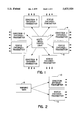
- FIG. 1 shows a block diagram of the parts of the system according to the invention located at one multi-way traffic light.
- FIG. 2 shows a block diagram of the parts of the system located at a warning sign.
- FIG. 3 shows a block diagram of the parts of the system located at an individual vehicle.
- FIG. 4 shows circuit details of one of the Direction Encoder-Transmitters shown in FIG. 1.
- FIG. 5 shows circuit details of one of the Status Encoder-Transmitters shown in FIG. 1.
- FIG. 6 shows details of the Direction Receiver-Demodulator shown in FIG. 3.
- FIG. 7 shows details of the Status Receiver-Demodulator shown in FIG. 3.
- FIG. 8 shows details one of the Direction Decoders shown in FIG. 3.
- FIG. 9 shows further details of the Direction Receiver-Demodulator of FIG. 6.
- FIGS. 10A and 10B show timing diagrams of the input to and the output from the Direction Receiver-Demodulator of FIG. 3.
- FIG. 10A illustrates the input and
- FIG. 10B illustrates the output.
- FIG. 11 illustrates an embodiment of the invention utilizing different types of radiant energy for transmitting direction and status signals.
- FIG. 1 shows a block diagram of the components of the invention at a multi-sided traffic light installation.
- Block 2 represents an ordinary arrangement of traffic lights at an intersection of two streets or roads.
- the lights can be on a single four-sided fixture or in four or more separate fixtures. Mechanical or electrical connections from the lights are used to activate the Direction Encoder-Transmitters 4 and the Status Encoder-Transmitters 6. For a four way installation there would be four pairs of these encoder-transmitters. Of course instead of four roads coming together, the intersection could be formed by the meeting of three, five or more roads. Details of the encoder-transmitters will be discussed later with reference to FIGS. 4 and 5.
- FIG. 2 shows a block diagram of one such installation.
- the warning sign 8 could be any one of several types of signs such as those just mentioned.
- the Direction Encoder-Transmitter 10 could be similar to the equivalent equipment in FIG. 1.
- the accompanying Status Encoder-Transmitter 12 could continuously transmit an encoded signal which would correspond to the message on the sign itself.
- the transmitters could be turned off when not needed.
- the SCHOOL ZONE transmitter could be turned off when the school was not in operation.
- FIG. 3 shows a block diagram of the equipment which would be installed on a vehicle according to the invention.
- Each vehicle would include a Direction Receiver-Demodulator 14 with a Direction Decoder 16 as well as a Status Receiver-Demodulator 18 and accompanying Decoders 20 through 28 and Alarms 30 through 38.
- the details of the receiver-demodulators are discussed below in reference to FIGS. 6-9, 10A and 10B.
- Direction Decoder 16 When a direction signal is received and demodulated by Receiver-Demodulator 14, it is decoded by Direction Decoder 16. If the received signal is a valid, properly coded direction signal, the output of Direction Decoder 16 enables the Status Receiver-Demodulator 18 to receive and demodulate the status signal and pass the demodulated status signal to the bank of Decoders 20-28.
- decoders can determine if a red, yellow, green or other signal has been received and then a corresponding visual alarm, audio alarm or message is energized within the vehicle.
- the devices for generating the visual alarm, audio alarms or messages are represented as Alarms 30-38 in FIG. 3.
- the system can also have decoders for other types of warning signs.
- Decoders 26 and 28 and Alarms 36 and 38 are indicated as Decoder 28 and Alarm 38 in dashed form to indicate that the number of decoders and alarm devices installed in vehicles can vary depending upon the actual system involved.
- FIG. 4 illustrates a simple circuit for implementing the Encoder-Transmitters such as block in FIG. 1.
- the 556 integrated circuit 40 is a dual timer circuit such as that described in detail in the book Integrated Circuit and Waveform Generator Handbook by R. M. Marston (1990), pages 87-88 and Radio Shack's Engineer's Mini-Notebook--555 Timer IC Circuits by Forrest M. Mims (1984), pages 10-23.
- the pin-outs for the 556 IC dual timer 40 are as follows:
- the 556 IC can be used in the encoder-transmitters in the present invention by setting the first timer to oscillate at a first frequency and allowing the output on pin 5 of this first timer to control the oscillation of the second timer. The frequencies are adjusted by choosing the proper values for the accompanying resistors and capacitors.
- the output on pin 9 of the second timer can be used to drive an infrared transmitter 50. The output on pin 9 may be amplified before being applied to the radiant energy transmitter 50 and the transmitter will be chosen to generate an infrared signal having the desired power.
- the frequency generated by the first timer is called the encode frequency herein and may be set to a value of 100 to 1000 Hz, while the frequency generated by the second timer is called the carrier frequency herein and may be set at 40 kHz.
- the output of the circuit shown in FIG. 4 would be bursts of 40 kHz signals separated by time intervals during which the second timer is not oscillating.
- This output is transmitted and is illustrated in FIG. 10A.
- the clusters of vertical lines in FIG. 10A are meant to signify the bursts of the 40 kHz carrier frequency.
- the encode frequency is set essentially by the charge and discharge times of capacitor 42 in FIG. 4. This capacitor is charged through resistors 44, 46 and 48 and discharged through resistors 46 and 48.
- capacitor 42 and resistors 44, 46 and 48 can be chosen to set the encode frequency.
- the carrier frequency is set essentially by the charge and discharge times of capacitor 52. This capacitor is charged through resistors 54 and 56 and discharged through resistor 56.
- the values of the elements 52, 54 and 56 can be chosen to set the carrier frequency.
- the Status Encoder-Transmitters for example block 6 in FIG. 1, are similar to the Direction Encoder-Transmitters but the status encoders are arranged so that the encode frequency changes as the traffic light changes from green to yellow to red.
- the carrier frequency produced by the Status Encoder-Transmitter may be the same as the carrier frequency produced by the Direction Encoder-Transmitters or may be an entirely different carrier frequency.
- FIG. 5 shows a partial view of a Status Encoder-Transmitter wherein components which act similarly to those in the Direction Encoder-Transmitter of FIG. 4 are given similar numbers with a letter added. It can be seen that the encode frequency, which is produced by the first timer in the 556 dual timer, can be changed by switching-in different sized capacitors. Just as the charge time and discharge time of capacitor 42 in FIG. 4 is used in determining the encode frequency of the Direction Encoder-Transmitter in FIG. 4, capacitors 42a, 42b and 42c in FIG. 5 are used in determining the encode frequencies of the Status Encoder-Transmitter for red, yellow and green signals. These capacitors are switched in and out of the timer circuit under control of the traffic light.
- the switches 58a, 58b and 58c may be electro-mechanical or electronic. When the traffic light turns green, switch 58a is closed and capacitor 42a is used in determining the encode frequency which then triggers on and off the carrier frequency transmitted by the Status Encoder-Transmitter. Of course, other methods could be devised to produce the different encode frequencies for the different traffic light colors.
- FIG. 10A shows a timing diagram of the transmitted signal. It illustrates bursts of infrared light with each burst comprising infrared blinking on and off at the carrier frequency (e.g 40 kHz) and the carrier frequency is triggered on and off at the encode frequency (e.g 150 Hz).
- the carrier frequency e.g 40 kHz
- the encode frequency e.g 150 Hz
- FIG. 6 shows some of the details of such a Direction Receiver-Demodulator 14.
- Element 61 in FIG. 6 can be a GP1U52X infrared receiver-demodulator available from Radio Shack (Cat. No. 276-137).
- the GP1U52X is presented only as an example of a type of element which can perform the required functions of a receiver-demodulator. Obviously, the receiver-demodulator could be built using other hardware components.
- the GP1U52X is a hybrid IC/infrared detector with a photo diode that has its peak sensitivity in the near infrared range and has a built-in filter to block visible light.
- FIG. 9 shows a block diagram of the internal operation of the GP1U52X.
- the output of photo diode 90 feeds into preamplifier 91 and limiter 92 to provide a clean signal to the rest of the circuit.
- Band pass filter 93 rejects all signals outside the band pass.
- the band pass is 40 kHz ⁇ 4 kHz but other carrier frequencies and band pass widths could be used.
- the remaining signal is fed to demodulator 94, integrator 95 and waveshaper circuit 96.
- the output of waveshaper 96 appears on line 97 and as can be seen in FIG. 6 this output drives a one-transistor amplifier 62 whose output appears on line 42.
- the output of the waveshaper is shown in FIG. 10B and it can be seen that it is an envelope of the received signal shown in FIG. 10A with the 40 kHz carrier frequency removed. This envelope is a series of rectangular pulses whose frequency is equal to the encode frequency.
- FIG. 3 shows a diagram of a 567 IC chip 80 which can be used to implement a decoder such as Direction Decoder 16.
- the operation of a 567 IC is explained on pages 214-225 of Marston's handbook cited above.
- the decoder could be constructed using other components than the 567 IC chip.
- the 567 IC chip 80 shown in FIG. 8 includes a voltage controlled oscillator (VCO) which is set to generate internally a frequency equal to the encode frequency. This frequency is compared with the frequency received on terminal 3 of the chip via line 42. When the input frequency on line 42 coincides with the internally generated frequency, the output on terminal 8 is pulled toward ground and this ground signal is available on line 44 which is connected to Status Receiver-Demodulator 18 in FIG. 3.
- VCO voltage controlled oscillator
- FIG. 7 shows that terminal 3 of the GP1U52X chip 71 in FIG. 7 is not connected directly to ground.
- FIG. 6 shows that in the Direction Receiver-Demodulator 14 terminal 3 of chip 61 is permanently connected to ground. Thus Direction Receiver-Demodulator 14 is continuously ready to receive the incoming infrared signals.
- FIG. 7 shows that terminal 3 of chip 71 is not permanently connected to ground so that the Status Receiver-Demodulator 18 is not continuously enabled to receive an incoming infrared signal. It can be seen that the Status Receiver-Demodulator is activated only if a valid
- Direction signal is found present by the Direction Receiver-Demodulator 14.
- the simultaneous reception of a valid Direction signal and a valid Status signal is required before a warning signal is issued in the vehicle. In this way false signals are minimized.
- FIGS. 6, 7 and 8 show how the activation of the Status Receiver-Demodulator 18 of FIG. 7 is accomplished.
- an infrared signal of the proper wavelength modulated with the proper carrier frequency is received by Direction Receiver-Demodulator 14 of FIG. 6, it is demodulated whereby the carrier frequency is removed and the demodulated signal which includes the encode frequency is output on line 42 and forwarded to the Direction Decoder 16 in FIG. 8.
- Decoder 16 receives this demodulated signal and, if it determines that the proper encode frequency is present, a signal is output on line 44. The signal on line 44 is then forwarded to the Status Receiver-Demodulator 18 shown in FIG. 7 where it enables the receiver-demodulator chip 71 to accept a status signal.
- the demodulated Status signal is presented simultaneously to red, yellow, green and/or other warning decoders.
- FIG. 3 where the demodulated output of Status Receiver/Demodulator 18 is fed simultaneously to decoders 20, 22, 24, 26 and 28.
- decoders 20, 22, 24, 26 and 28 These decoders check the encode frequency of the demodulated status signal to determine whether it corresponds to the red, yellow, green or other encode frequency. If one of the decoders finds a proper encode frequency, the corresponding alarm is activated. For example, if Red Decoder 20 receives its encode signal, Red Alarm 30 will light.
- the red, yellow, green, etc. decoders of FIG. 3 perform their functions in the same way as Direction Decoder 16 shown in FIG. 8 described above.
- the chances of false signals can be reduced even further by using different kinds of highly directional radiant energy to transmit the Direction signals and to transmit the Status signals.
- An embodiment incorporating this feature is illustrated in FIG. 11.
- the Direction signals are transmitted as laser signals while the Status signals are transmitted as infrared signals.
- the signals can be transmitted with selected carrier frequencies and selected encode frequencies.
Abstract
Description
______________________________________ FUNCTION 1st TIMER 2nd TIMER ______________________________________Ground 7 7Trigger 6 8Output 5 9Reset 4 10Control V 3 11Threshold 2 12Discharge 1 13Vcc 14 14 ______________________________________
Claims (11)
Priority Applications (1)
| Application Number | Priority Date | Filing Date | Title |
|---|---|---|---|
| US08/348,869 US5635920A (en) | 1994-11-29 | 1994-11-29 | Remote traffic signal indicator |
Applications Claiming Priority (1)
| Application Number | Priority Date | Filing Date | Title |
|---|---|---|---|
| US08/348,869 US5635920A (en) | 1994-11-29 | 1994-11-29 | Remote traffic signal indicator |
Publications (1)
| Publication Number | Publication Date |
|---|---|
| US5635920A true US5635920A (en) | 1997-06-03 |
Family
ID=23369908
Family Applications (1)
| Application Number | Title | Priority Date | Filing Date |
|---|---|---|---|
| US08/348,869 Expired - Fee Related US5635920A (en) | 1994-11-29 | 1994-11-29 | Remote traffic signal indicator |
Country Status (1)
| Country | Link |
|---|---|
| US (1) | US5635920A (en) |
Cited By (51)
| Publication number | Priority date | Publication date | Assignee | Title |
|---|---|---|---|---|
| GB2332551A (en) * | 1997-12-19 | 1999-06-23 | Daimler Benz Ag | Lighting system |
| WO1999035628A1 (en) * | 1998-01-07 | 1999-07-15 | Cobra Electronics Corp. | Transportation information warning system |
| US5940010A (en) * | 1997-07-31 | 1999-08-17 | Toyota Jidosha Kabushiki Kaisha | Intersection warning system |
| US6078279A (en) * | 1998-07-08 | 2000-06-20 | Cobra Electronics | Electromagnetic signal detector with mute feature |
| US6236336B1 (en) | 1999-02-24 | 2001-05-22 | Cobra Electronics Corp. | Traffic information warning system with single modulated carrier |
| US6262673B1 (en) * | 2000-05-30 | 2001-07-17 | Charleen L. Kalina | Roadway warning system |
| WO2002027690A1 (en) * | 2000-09-26 | 2002-04-04 | Dotson Alexander B | Audible stop light advance warning system |
| US20030016143A1 (en) * | 2001-07-23 | 2003-01-23 | Ohanes Ghazarian | Intersection vehicle collision avoidance system |
| US20030179106A1 (en) * | 2002-03-25 | 2003-09-25 | Neff Ryan A. | On-board vehicle system and method for receiving and indicating driving-related signals |
| US6683590B1 (en) | 1998-03-20 | 2004-01-27 | The University Of Hong Kong | Tricolor LED display system having audio output |
| EP1515292A1 (en) * | 2002-06-05 | 2005-03-16 | Sony Corporation | Communication system for vehicle, vehicle, and communication device for vehicle |
| US20050067557A1 (en) * | 2003-09-29 | 2005-03-31 | Edward Wong | Photoelectric controller and demonstrating apparatus simulating real life traffic means built in the photoelectric controller |
| US20050101678A1 (en) * | 2000-08-14 | 2005-05-12 | Andreas Natsch | Antibacterial composition |
| US20050137782A1 (en) * | 2003-12-17 | 2005-06-23 | Sony Corporation | Optical communication equipment and vehicle control method |
| US20050248468A1 (en) * | 2004-05-07 | 2005-11-10 | Glynn Alex P | Traffic stop sign safety enhancement system |
| US6965321B1 (en) | 2003-09-09 | 2005-11-15 | Abbas Arab | Vehicle notification system |
| US20060049963A1 (en) * | 2004-09-07 | 2006-03-09 | Smith Arthur E | Smith alert system |
| US20070242337A1 (en) * | 2006-04-17 | 2007-10-18 | Bradley James R | System and Method for Vehicular Communications |
| US20070242338A1 (en) * | 2006-04-17 | 2007-10-18 | James Roy Bradley | System and Method for Vehicular Communications |
| US20070242339A1 (en) * | 2006-04-17 | 2007-10-18 | James Roy Bradley | System and Method for Vehicular Communications |
| US20080088479A1 (en) * | 2006-10-13 | 2008-04-17 | Toyota Engineering & Manufacturing North America, Inc. | Traffic light warning method and system |
| US20080122607A1 (en) * | 2006-04-17 | 2008-05-29 | James Roy Bradley | System and Method for Vehicular Communications |
| US20080122606A1 (en) * | 2006-04-17 | 2008-05-29 | James Roy Bradley | System and Method for Vehicular Communications |
| US20090115632A1 (en) * | 2007-11-01 | 2009-05-07 | Lg Electronics Inc. | Terminal and computer program product for receiving traffic information, method of providing signal light information, and method of guiding signal |
| US20090299616A1 (en) * | 2008-05-30 | 2009-12-03 | Navteq North America, Llc | Data mining in a digital map database to identify intersections located over hills and enabling precautionary actions in a vehicle |
| US20090299632A1 (en) * | 2008-05-29 | 2009-12-03 | Delphi Technologies, Inc. | Vehicle Pre-Impact Sensing System Having Signal Modulation |
| US20090299630A1 (en) * | 2008-05-30 | 2009-12-03 | Navteq North America, Llc | Data mining in a digital map database to identify insufficient superelevation along roads and enabling precautionary actions in a vehicle |
| US20090299624A1 (en) * | 2008-05-30 | 2009-12-03 | Navteq North America, Llc | Data mining in a digital map database to identify speed changes on upcoming curves along roads and enabling precautionary actions in a vehicle |
| US20090299615A1 (en) * | 2008-05-30 | 2009-12-03 | Navteq North America, Llc | Data mining in a digital map database to identify insufficient merge lanes along roads and enabling precautionary actions in a vehicle |
| US20090299626A1 (en) * | 2008-05-30 | 2009-12-03 | Navteq North America, Llc | Data mining in a digital map database to identify unusually narrow lanes or roads and enabling precautionary actions in a vehicle |
| US20090300067A1 (en) * | 2008-05-30 | 2009-12-03 | Navteq North America, Llc | Data mining in a digital map database to identify decreasing radius of curvature along roads and enabling precautionary actions in a vehicle |
| US20090299622A1 (en) * | 2008-05-30 | 2009-12-03 | Navteq North America, Llc | Data mining to identify locations of potentially hazardous conditions for vehicle operation and use thereof |
| US20090299625A1 (en) * | 2008-05-30 | 2009-12-03 | Navteq North America, Llc | Data mining in a digital map database to identify blind intersections along roads and enabling precautionary actions in a vehicle |
| US20100073194A1 (en) * | 2002-07-22 | 2010-03-25 | Ohanes Ghazarian | Intersection vehicle collision avoidance system |
| CN102103798A (en) * | 2011-02-10 | 2011-06-22 | 惠州Tcl移动通信有限公司 | Traffic lights state information prompt system and method thereof |
| US20110187547A1 (en) * | 2010-02-01 | 2011-08-04 | Lg Electronics Inc. | Information display apparatus and method thereof |
| US20120095646A1 (en) * | 2009-09-15 | 2012-04-19 | Ghazarian Ohanes D | Intersection vehicle collision avoidance system |
| US20120253605A1 (en) * | 2008-05-30 | 2012-10-04 | Robert Denaro | Data mining in a digital map database to identify intersections located at hill bottoms and enabling precautionary actions in a vehicle |
| US20120313793A1 (en) * | 2011-06-07 | 2012-12-13 | Dustin Colin Huguenot | Truck mounted stop light display |
| AU2012205134B2 (en) * | 2011-07-14 | 2015-07-23 | Ge Global Sourcing Llc | System, method and device for conveying information from a wayside device |
| CN104821094A (en) * | 2015-05-22 | 2015-08-05 | 广东欧珀移动通信有限公司 | Traffic signal lamp reminding method and device |
| US9305460B1 (en) | 2013-10-28 | 2016-04-05 | John Justine Aza | Roadway warning light detector and method of warning a motorist |
| US9318021B2 (en) * | 2014-06-26 | 2016-04-19 | Jassem M. Al-Jasem Al-Qaneei | Vehicle mounted traffic light and system |
| US20170124870A1 (en) * | 2015-11-02 | 2017-05-04 | Magna Electronics Inc. | Driver assistance system with traffic light alert |
| CN106935049A (en) * | 2017-04-27 | 2017-07-07 | 上海博历机械科技有限公司 | A kind of intelligent vehicle early warning system |
| US9875653B2 (en) | 2013-08-26 | 2018-01-23 | Keyvan T. Diba | Electronic traffic alert system |
| WO2018232626A1 (en) * | 2017-06-21 | 2018-12-27 | 深圳支点电子智能科技有限公司 | Safety prompting method and smart watch |
| US20200111352A1 (en) * | 2017-11-27 | 2020-04-09 | Renato Martinez Openiano | Traffic Sign and System for Increasing Awareness of the Same |
| US10896605B2 (en) * | 2019-02-21 | 2021-01-19 | Juan Manuel Miranda | Communication system for traffic control equipment |
| US11334753B2 (en) | 2018-04-30 | 2022-05-17 | Uatc, Llc | Traffic signal state classification for autonomous vehicles |
| EP4195177A4 (en) * | 2020-08-20 | 2024-01-24 | Huawei Tech Co Ltd | Traffic signal identification method and apparatus |
Citations (14)
| Publication number | Priority date | Publication date | Assignee | Title |
|---|---|---|---|---|
| US2442851A (en) * | 1940-08-03 | 1948-06-08 | Farnsworth Res Corp | Traffic signaling system |
| US2968802A (en) * | 1957-04-26 | 1961-01-17 | Rca Corp | Radio signal receiving system |
| US3646580A (en) * | 1969-07-18 | 1972-02-29 | Raytheon Co | Surface vehicle fleet command and control system |
| US3899671A (en) * | 1974-02-27 | 1975-08-12 | Harris A Stover | Communication systems |
| US4228419A (en) * | 1978-08-09 | 1980-10-14 | Electronic Implementation Systems, Inc. | Emergency vehicle traffic control system |
| US4447800A (en) * | 1980-07-25 | 1984-05-08 | Nissan Motor Company, Limited | Obstacle detector for use in vehicles |
| US4816827A (en) * | 1986-04-14 | 1989-03-28 | Essacq Baloutch | Road safety installation with emission of sound messages |
| US4921468A (en) * | 1987-03-20 | 1990-05-01 | Aisin Seiki Kabushiki Kaisha | Space transmission optical communication system |
| US5126735A (en) * | 1990-03-09 | 1992-06-30 | Trevijano Jose J A | Inter-vehicle communication apparatus by means of infrared rays used to reduce acoustic noise pollution |
| US5172113A (en) * | 1991-10-24 | 1992-12-15 | Minnesota Mining And Manufacturing Company | System and method for transmitting data in an optical traffic preemption system |
| GB2265041A (en) * | 1992-03-13 | 1993-09-15 | Ronald Mark Henderson | Infra-red route and hazard system |
| US5280632A (en) * | 1990-11-26 | 1994-01-18 | Hyundai Electronics Industries Co., Ltd. | Method of transmitting and receiving warning broadcast signals during drive in dangerous area, and system thereof |
| US5289181A (en) * | 1990-11-29 | 1994-02-22 | Nissan Motor Co., Ltd. | Vehicle alarm system for informing other vehicles of its own presence |
| US5444742A (en) * | 1992-04-28 | 1995-08-22 | Robert Bosch Gmbh | System for bidirectional data transmission between a plurality of stationary units and a vehicle |
-
1994
- 1994-11-29 US US08/348,869 patent/US5635920A/en not_active Expired - Fee Related
Patent Citations (14)
| Publication number | Priority date | Publication date | Assignee | Title |
|---|---|---|---|---|
| US2442851A (en) * | 1940-08-03 | 1948-06-08 | Farnsworth Res Corp | Traffic signaling system |
| US2968802A (en) * | 1957-04-26 | 1961-01-17 | Rca Corp | Radio signal receiving system |
| US3646580A (en) * | 1969-07-18 | 1972-02-29 | Raytheon Co | Surface vehicle fleet command and control system |
| US3899671A (en) * | 1974-02-27 | 1975-08-12 | Harris A Stover | Communication systems |
| US4228419A (en) * | 1978-08-09 | 1980-10-14 | Electronic Implementation Systems, Inc. | Emergency vehicle traffic control system |
| US4447800A (en) * | 1980-07-25 | 1984-05-08 | Nissan Motor Company, Limited | Obstacle detector for use in vehicles |
| US4816827A (en) * | 1986-04-14 | 1989-03-28 | Essacq Baloutch | Road safety installation with emission of sound messages |
| US4921468A (en) * | 1987-03-20 | 1990-05-01 | Aisin Seiki Kabushiki Kaisha | Space transmission optical communication system |
| US5126735A (en) * | 1990-03-09 | 1992-06-30 | Trevijano Jose J A | Inter-vehicle communication apparatus by means of infrared rays used to reduce acoustic noise pollution |
| US5280632A (en) * | 1990-11-26 | 1994-01-18 | Hyundai Electronics Industries Co., Ltd. | Method of transmitting and receiving warning broadcast signals during drive in dangerous area, and system thereof |
| US5289181A (en) * | 1990-11-29 | 1994-02-22 | Nissan Motor Co., Ltd. | Vehicle alarm system for informing other vehicles of its own presence |
| US5172113A (en) * | 1991-10-24 | 1992-12-15 | Minnesota Mining And Manufacturing Company | System and method for transmitting data in an optical traffic preemption system |
| GB2265041A (en) * | 1992-03-13 | 1993-09-15 | Ronald Mark Henderson | Infra-red route and hazard system |
| US5444742A (en) * | 1992-04-28 | 1995-08-22 | Robert Bosch Gmbh | System for bidirectional data transmission between a plurality of stationary units and a vehicle |
Cited By (94)
| Publication number | Priority date | Publication date | Assignee | Title |
|---|---|---|---|---|
| US5940010A (en) * | 1997-07-31 | 1999-08-17 | Toyota Jidosha Kabushiki Kaisha | Intersection warning system |
| FR2772960A1 (en) * | 1997-12-19 | 1999-06-25 | Daimler Benz Ag | LIGHTING INSTALLATION |
| GB2332551B (en) * | 1997-12-19 | 1999-10-27 | Daimler Benz Ag | Lighting system |
| GB2332551A (en) * | 1997-12-19 | 1999-06-23 | Daimler Benz Ag | Lighting system |
| WO1999035628A1 (en) * | 1998-01-07 | 1999-07-15 | Cobra Electronics Corp. | Transportation information warning system |
| US6683590B1 (en) | 1998-03-20 | 2004-01-27 | The University Of Hong Kong | Tricolor LED display system having audio output |
| US6078279A (en) * | 1998-07-08 | 2000-06-20 | Cobra Electronics | Electromagnetic signal detector with mute feature |
| US6236336B1 (en) | 1999-02-24 | 2001-05-22 | Cobra Electronics Corp. | Traffic information warning system with single modulated carrier |
| US6262673B1 (en) * | 2000-05-30 | 2001-07-17 | Charleen L. Kalina | Roadway warning system |
| US20050101678A1 (en) * | 2000-08-14 | 2005-05-12 | Andreas Natsch | Antibacterial composition |
| WO2002027690A1 (en) * | 2000-09-26 | 2002-04-04 | Dotson Alexander B | Audible stop light advance warning system |
| US20030016143A1 (en) * | 2001-07-23 | 2003-01-23 | Ohanes Ghazarian | Intersection vehicle collision avoidance system |
| US20030179106A1 (en) * | 2002-03-25 | 2003-09-25 | Neff Ryan A. | On-board vehicle system and method for receiving and indicating driving-related signals |
| US6850170B2 (en) * | 2002-03-25 | 2005-02-01 | Ryan A. Neff | On-board vehicle system and method for receiving and indicating driving-related signals |
| EP1515292A1 (en) * | 2002-06-05 | 2005-03-16 | Sony Corporation | Communication system for vehicle, vehicle, and communication device for vehicle |
| US20060119489A1 (en) * | 2002-06-05 | 2006-06-08 | Sony Corporation | Communication system for vehicle, vehicle, and communication device for vehicle |
| US7548172B2 (en) | 2002-06-05 | 2009-06-16 | Sony Corporation | Communication system for vehicle, vehicle, and communication device for vehicle |
| EP1515292A4 (en) * | 2002-06-05 | 2006-01-18 | Sony Corp | Communication system for vehicle, vehicle, and communication device for vehicle |
| US8068036B2 (en) * | 2002-07-22 | 2011-11-29 | Ohanes Ghazarian | Intersection vehicle collision avoidance system |
| US20100073194A1 (en) * | 2002-07-22 | 2010-03-25 | Ohanes Ghazarian | Intersection vehicle collision avoidance system |
| US6965321B1 (en) | 2003-09-09 | 2005-11-15 | Abbas Arab | Vehicle notification system |
| US20050067557A1 (en) * | 2003-09-29 | 2005-03-31 | Edward Wong | Photoelectric controller and demonstrating apparatus simulating real life traffic means built in the photoelectric controller |
| US7383121B2 (en) * | 2003-12-17 | 2008-06-03 | Sony Corporation | Optical communication equipment and vehicle control method |
| US20050137782A1 (en) * | 2003-12-17 | 2005-06-23 | Sony Corporation | Optical communication equipment and vehicle control method |
| US7109884B2 (en) * | 2004-05-07 | 2006-09-19 | Glynntech, Inc. | Traffic stop sign safety enhancement system |
| US20050248468A1 (en) * | 2004-05-07 | 2005-11-10 | Glynn Alex P | Traffic stop sign safety enhancement system |
| US20060049963A1 (en) * | 2004-09-07 | 2006-03-09 | Smith Arthur E | Smith alert system |
| US20070242339A1 (en) * | 2006-04-17 | 2007-10-18 | James Roy Bradley | System and Method for Vehicular Communications |
| US20080122606A1 (en) * | 2006-04-17 | 2008-05-29 | James Roy Bradley | System and Method for Vehicular Communications |
| US20080122607A1 (en) * | 2006-04-17 | 2008-05-29 | James Roy Bradley | System and Method for Vehicular Communications |
| US20070242338A1 (en) * | 2006-04-17 | 2007-10-18 | James Roy Bradley | System and Method for Vehicular Communications |
| US20070242337A1 (en) * | 2006-04-17 | 2007-10-18 | Bradley James R | System and Method for Vehicular Communications |
| US7961086B2 (en) | 2006-04-17 | 2011-06-14 | James Roy Bradley | System and method for vehicular communications |
| US20080088479A1 (en) * | 2006-10-13 | 2008-04-17 | Toyota Engineering & Manufacturing North America, Inc. | Traffic light warning method and system |
| US20090115632A1 (en) * | 2007-11-01 | 2009-05-07 | Lg Electronics Inc. | Terminal and computer program product for receiving traffic information, method of providing signal light information, and method of guiding signal |
| US7825825B2 (en) * | 2007-11-01 | 2010-11-02 | Lg Electronics Inc. | Terminal and computer program product for receiving traffic information, method of providing signal light information, and method of guiding signal |
| US8249798B2 (en) * | 2008-05-29 | 2012-08-21 | Delphi Technologies, Inc. | Vehicle pre-impact sensing system having signal modulation |
| US20090299632A1 (en) * | 2008-05-29 | 2009-12-03 | Delphi Technologies, Inc. | Vehicle Pre-Impact Sensing System Having Signal Modulation |
| US20090299615A1 (en) * | 2008-05-30 | 2009-12-03 | Navteq North America, Llc | Data mining in a digital map database to identify insufficient merge lanes along roads and enabling precautionary actions in a vehicle |
| US20090299622A1 (en) * | 2008-05-30 | 2009-12-03 | Navteq North America, Llc | Data mining to identify locations of potentially hazardous conditions for vehicle operation and use thereof |
| US20090299625A1 (en) * | 2008-05-30 | 2009-12-03 | Navteq North America, Llc | Data mining in a digital map database to identify blind intersections along roads and enabling precautionary actions in a vehicle |
| US20090300067A1 (en) * | 2008-05-30 | 2009-12-03 | Navteq North America, Llc | Data mining in a digital map database to identify decreasing radius of curvature along roads and enabling precautionary actions in a vehicle |
| US20090299626A1 (en) * | 2008-05-30 | 2009-12-03 | Navteq North America, Llc | Data mining in a digital map database to identify unusually narrow lanes or roads and enabling precautionary actions in a vehicle |
| US9733093B2 (en) | 2008-05-30 | 2017-08-15 | Here Global B.V. | Data mining to identify locations of potentially hazardous conditions for vehicle operation and use thereof |
| US11119493B2 (en) | 2008-05-30 | 2021-09-14 | Here Global B.V. | Data mining in a digital map database to identify unusually narrow lanes or roads and enabling precautionary actions in a vehicle |
| US10648818B2 (en) | 2008-05-30 | 2020-05-12 | Here Global B.V. | Data mining in a digital map database to identify blind intersections along roads and enabling precautionary actions in a vehicle |
| US20090299624A1 (en) * | 2008-05-30 | 2009-12-03 | Navteq North America, Llc | Data mining in a digital map database to identify speed changes on upcoming curves along roads and enabling precautionary actions in a vehicle |
| US20090299630A1 (en) * | 2008-05-30 | 2009-12-03 | Navteq North America, Llc | Data mining in a digital map database to identify insufficient superelevation along roads and enabling precautionary actions in a vehicle |
| US20090299616A1 (en) * | 2008-05-30 | 2009-12-03 | Navteq North America, Llc | Data mining in a digital map database to identify intersections located over hills and enabling precautionary actions in a vehicle |
| US20120253605A1 (en) * | 2008-05-30 | 2012-10-04 | Robert Denaro | Data mining in a digital map database to identify intersections located at hill bottoms and enabling precautionary actions in a vehicle |
| US10648817B2 (en) | 2008-05-30 | 2020-05-12 | Here Global B.V. | Data mining in a digital map database to identify speed changes on upcoming curves along roads and enabling precautionary actions in a vehicle |
| US10627240B2 (en) | 2008-05-30 | 2020-04-21 | Here Global B.V. | Data mining in a digital map database to identify decreasing radius of curvature along roads and enabling precautionary actions in a vehicle |
| US8531318B2 (en) * | 2008-05-30 | 2013-09-10 | Navteq B.V. | Data mining in a digital map database to identify intersections located at hill bottoms and enabling precautionary actions in a vehicle |
| US8688369B2 (en) | 2008-05-30 | 2014-04-01 | Navteq B.V. | Data mining in a digital map database to identify blind intersections along roads and enabling precautionary actions in a vehicle |
| US8698649B2 (en) | 2008-05-30 | 2014-04-15 | Navteq B.V. | Data mining in a digital map database to identify decreasing radius of curvature along roads and enabling precautionary actions in a vehicle |
| US10612931B2 (en) | 2008-05-30 | 2020-04-07 | Here Global B.V. | Data mining in a digital map database to identify intersections located at hill bottoms and enabling precautionary actions in a vehicle |
| US10578442B2 (en) | 2008-05-30 | 2020-03-03 | Here Global B.V. | Data mining to identify locations of potentially hazardous conditions for vehicle operation and use thereof |
| US8775073B2 (en) | 2008-05-30 | 2014-07-08 | Navteq B.V. | Data mining in a digital map database to identify insufficient merge lanes along roads and enabling precautionary actions in a vehicle |
| US9035804B2 (en) | 2008-05-30 | 2015-05-19 | Here Global B.V. | Data mining in a digital map database to identify intersections located at hill bottoms and enabling precautionary actions in a vehicle |
| US9043127B2 (en) | 2008-05-30 | 2015-05-26 | Here Global B.V. | Data mining in a digital map database to identify blind intersections along roads and enabling precautionary actions in a vehicle |
| US10359781B2 (en) | 2008-05-30 | 2019-07-23 | Here Global B.V. | Data mining in a digital map database to identify unusually narrow lanes or roads and enabling precautionary actions in a vehicle |
| US10323945B2 (en) | 2008-05-30 | 2019-06-18 | Here Global B.V. | Data mining to identify locations of potentially hazardous conditions for vehicle operation and use thereof |
| US9121716B2 (en) | 2008-05-30 | 2015-09-01 | Here Global B.V. | Data mining in a digital map database to identify insufficient superelevation along roads and enabling precautionary actions in a vehicle |
| US9134133B2 (en) | 2008-05-30 | 2015-09-15 | Here Global B.V. | Data mining to identify locations of potentially hazardous conditions for vehicle operation and use thereof |
| US9182241B2 (en) | 2008-05-30 | 2015-11-10 | Here Global B.V. | Data mining in a digital map database to identify unusually narrow lanes or roads and enabling precautionary actions in a vehicle |
| US9228844B2 (en) | 2008-05-30 | 2016-01-05 | Here Global B.V. | Data mining in a digital map database to identify insufficient merge lanes along roads and enabling precautionary actions in a vehicle |
| US9279688B2 (en) | 2008-05-30 | 2016-03-08 | Here Global B.V. | Data mining in a digital map database to identify blind intersections along roads and enabling precautionary actions in a vehicle |
| US10012510B2 (en) | 2008-05-30 | 2018-07-03 | Here Global B.V. | Data mining in a digital map database to identify decreasing radius of curvature along roads and enabling precautionary actions in a vehicle |
| US9909881B2 (en) | 2008-05-30 | 2018-03-06 | Here Global B.V. | Data mining in a digital map database to identify insufficient superelevation along roads and enabling precautionary actions in a vehicle |
| US9399468B2 (en) | 2008-05-30 | 2016-07-26 | Here Global B.V. | Data mining in a digital map database to identify intersections located at hill bottoms and enabling precautionary actions in a vehicle |
| US9797735B2 (en) | 2008-05-30 | 2017-10-24 | Here Global B.V. | Data mining in a digital map database to identify blind intersections along roads and enabling precautionary actions in a vehicle |
| US9752884B2 (en) | 2008-05-30 | 2017-09-05 | Here Global B.V. | Data mining in a digital map database to identify insufficient merge lanes along roads and enabling precautionary actions in a vehicle |
| US20120095646A1 (en) * | 2009-09-15 | 2012-04-19 | Ghazarian Ohanes D | Intersection vehicle collision avoidance system |
| US8773281B2 (en) * | 2009-09-15 | 2014-07-08 | Ohanes D. Ghazarian | Intersection vehicle collision avoidance system |
| US20110187547A1 (en) * | 2010-02-01 | 2011-08-04 | Lg Electronics Inc. | Information display apparatus and method thereof |
| US8395522B2 (en) | 2010-02-01 | 2013-03-12 | Lg Electronics, Inc. | Information display apparatus and method thereof |
| CN102103798B (en) * | 2011-02-10 | 2014-04-16 | 惠州Tcl移动通信有限公司 | Traffic lights state information prompt system and method thereof |
| CN102103798A (en) * | 2011-02-10 | 2011-06-22 | 惠州Tcl移动通信有限公司 | Traffic lights state information prompt system and method thereof |
| US20120313793A1 (en) * | 2011-06-07 | 2012-12-13 | Dustin Colin Huguenot | Truck mounted stop light display |
| AU2012205134B2 (en) * | 2011-07-14 | 2015-07-23 | Ge Global Sourcing Llc | System, method and device for conveying information from a wayside device |
| US9875653B2 (en) | 2013-08-26 | 2018-01-23 | Keyvan T. Diba | Electronic traffic alert system |
| US9305460B1 (en) | 2013-10-28 | 2016-04-05 | John Justine Aza | Roadway warning light detector and method of warning a motorist |
| US9318021B2 (en) * | 2014-06-26 | 2016-04-19 | Jassem M. Al-Jasem Al-Qaneei | Vehicle mounted traffic light and system |
| CN104821094A (en) * | 2015-05-22 | 2015-08-05 | 广东欧珀移动通信有限公司 | Traffic signal lamp reminding method and device |
| US20170124870A1 (en) * | 2015-11-02 | 2017-05-04 | Magna Electronics Inc. | Driver assistance system with traffic light alert |
| US10152886B2 (en) | 2015-11-02 | 2018-12-11 | Magna Electronics Inc. | Driver assistance system with traffic light alert |
| US9881501B2 (en) * | 2015-11-02 | 2018-01-30 | Magna Electronics Inc. | Driver assistance system with traffic light alert |
| CN106935049A (en) * | 2017-04-27 | 2017-07-07 | 上海博历机械科技有限公司 | A kind of intelligent vehicle early warning system |
| WO2018232626A1 (en) * | 2017-06-21 | 2018-12-27 | 深圳支点电子智能科技有限公司 | Safety prompting method and smart watch |
| US20200111352A1 (en) * | 2017-11-27 | 2020-04-09 | Renato Martinez Openiano | Traffic Sign and System for Increasing Awareness of the Same |
| US10755562B2 (en) * | 2017-11-27 | 2020-08-25 | Renato Martinez Openiano | Traffic sign and system for increasing awareness of the same |
| US11334753B2 (en) | 2018-04-30 | 2022-05-17 | Uatc, Llc | Traffic signal state classification for autonomous vehicles |
| US10896605B2 (en) * | 2019-02-21 | 2021-01-19 | Juan Manuel Miranda | Communication system for traffic control equipment |
| EP4195177A4 (en) * | 2020-08-20 | 2024-01-24 | Huawei Tech Co Ltd | Traffic signal identification method and apparatus |
Similar Documents
| Publication | Publication Date | Title |
|---|---|---|
| US5635920A (en) | Remote traffic signal indicator | |
| US5917430A (en) | Radar based highway safety warning system | |
| US6822580B2 (en) | Emergency vehicle warning system | |
| US4325057A (en) | School bus approach notification method and apparatus | |
| US6707391B1 (en) | Supplemental automotive traffic safety apparatus and method | |
| US2355607A (en) | Control system | |
| US5495243A (en) | Emergency vehicle alarm system for vehicles | |
| US6160493A (en) | Radio warning system for hazard avoidance | |
| AU597287B2 (en) | Emergency vehicle warning and traffic control system | |
| US5889475A (en) | Warning system for emergency vehicles | |
| CA2169037C (en) | Traffic control system using light emitting diodes | |
| US3760349A (en) | Emergency warning system | |
| US4100529A (en) | Road hazard warning system, indicating specific hazard | |
| US8884783B2 (en) | Systems and method for controlling preemption of a traffic signal | |
| US3938080A (en) | System for the programmed flashing of warning lights | |
| US6850170B2 (en) | On-board vehicle system and method for receiving and indicating driving-related signals | |
| US20130027221A1 (en) | Warning system for an intersection | |
| US5739768A (en) | Train proximity detector | |
| US6064301A (en) | Roadway deviation prevention system | |
| US4621252A (en) | Safety apparatus | |
| US6262673B1 (en) | Roadway warning system | |
| EP0349470A3 (en) | Remote guidance- and information system for drivers and pedestrians in road traffic areas | |
| EP0715748A1 (en) | Vehicle stop warning system | |
| US9142130B1 (en) | Light emitting road safety device with sound activation | |
| EP0510131B1 (en) | Electronic equipement for prevention of collisions between vehicles |
Legal Events
| Date | Code | Title | Description |
|---|---|---|---|
| AS | Assignment |
Owner name: J.B. POGUE, TEXAS Free format text: ASSIGNMENT OF ASSIGNORS INTEREST;ASSIGNOR:COPE, JOHN E.;REEL/FRAME:007300/0034 Effective date: 19941123 |
|
| AS | Assignment |
Owner name: VANCE, GLENN R., TEXAS Free format text: ASSIGNMENT OF AN UNDIVIDED 15% INTEREST;ASSIGNOR:COPE, JOHN E.;REEL/FRAME:007466/0791 Effective date: 19941123 |
|
| FEPP | Fee payment procedure |
Free format text: PAYOR NUMBER ASSIGNED (ORIGINAL EVENT CODE: ASPN); ENTITY STATUS OF PATENT OWNER: SMALL ENTITY |
|
| REMI | Maintenance fee reminder mailed | ||
| LAPS | Lapse for failure to pay maintenance fees | ||
| FP | Lapsed due to failure to pay maintenance fee |
Effective date: 20010603 |
|
| STCH | Information on status: patent discontinuation |
Free format text: PATENT EXPIRED DUE TO NONPAYMENT OF MAINTENANCE FEES UNDER 37 CFR 1.362 |