US5634224A - Inflatable cushioning device with self opening intake valve - Google Patents
Inflatable cushioning device with self opening intake valve Download PDFInfo
- Publication number
- US5634224A US5634224A US08/291,551 US29155194A US5634224A US 5634224 A US5634224 A US 5634224A US 29155194 A US29155194 A US 29155194A US 5634224 A US5634224 A US 5634224A
- Authority
- US
- United States
- Prior art keywords
- envelope
- pressure
- fluid
- load
- cushioning device
- Prior art date
- Legal status (The legal status is an assumption and is not a legal conclusion. Google has not performed a legal analysis and makes no representation as to the accuracy of the status listed.)
- Expired - Lifetime
Links
Images


Classifications
-
- A—HUMAN NECESSITIES
- A47—FURNITURE; DOMESTIC ARTICLES OR APPLIANCES; COFFEE MILLS; SPICE MILLS; SUCTION CLEANERS IN GENERAL
- A47C—CHAIRS; SOFAS; BEDS
- A47C27/00—Spring, stuffed or fluid mattresses or cushions specially adapted for chairs, beds or sofas
- A47C27/08—Fluid mattresses or cushions
- A47C27/088—Fluid mattresses or cushions incorporating elastic bodies, e.g. foam
-
- A—HUMAN NECESSITIES
- A47—FURNITURE; DOMESTIC ARTICLES OR APPLIANCES; COFFEE MILLS; SPICE MILLS; SUCTION CLEANERS IN GENERAL
- A47C—CHAIRS; SOFAS; BEDS
- A47C27/00—Spring, stuffed or fluid mattresses or cushions specially adapted for chairs, beds or sofas
- A47C27/08—Fluid mattresses or cushions
- A47C27/081—Fluid mattresses or cushions of pneumatic type
-
- A—HUMAN NECESSITIES
- A47—FURNITURE; DOMESTIC ARTICLES OR APPLIANCES; COFFEE MILLS; SPICE MILLS; SUCTION CLEANERS IN GENERAL
- A47C—CHAIRS; SOFAS; BEDS
- A47C27/00—Spring, stuffed or fluid mattresses or cushions specially adapted for chairs, beds or sofas
- A47C27/08—Fluid mattresses or cushions
- A47C27/10—Fluid mattresses or cushions with two or more independently-fillable chambers
Definitions
- This invention relates to a cushioning device for a mattress, sofa, seat or the like wherein partial support is obtained from a fluid, such as air.
- this invention relates to a combination of a resilient member, and an impervious envelope having intake and exhaust valves which make up a deformable and reformable cushion.
- U.S. Pat. No. 5,070,560 provides a mattress structure in which air cells have a valve for manually inflating or deflating individual air cells to desired pressures to relieve bed sores.
- the present invention provides an envelope containing a fluid and has exhaust and intake valves.
- a load is applied to the envelope, e.g. by a person resting on it, the fluid exhausts as the envelope conforms to the body shape of a person resting on it but maintains sufficient pressure to support the person on a cushion of fluid.
- the exhaust valve acts as a pressure relief valve to permit exhaustion of fluid when pressure within the envelope exceeds a predetermined threshold pressure.
- the exhaust valve is adjustable so that it may be preset to different threshold pressures.
- An intake valve means is provided to refill the envelope.
- the intake valve is a one way valve that only permits intake of fluid when pressure within the envelope is less than the pressure of fluid supply. Pressure within the envelope will decrease as the load is lifted from it.
- a resilient means is provided to reform the envelope after the load is lifted from it.
- the weight of a person resting on the envelope deforms the envelope.
- the fluid pressure within the envelope increases as the volume of the envelope decreases under deformation. Further, as the envelope deforms to conform to the irregular shape of a person, the area of the envelope supporting the load increases. Equilibrium is achieved when the forces within the envelope, including pressure of the fluid within the envelope multiplied by the area of the envelope supporting the load, equal the weight of the load.
- the provision of a pressure relief valve on the envelope permits gradual deflation of the envelope to facilitate conformation to a person's shape resulting in an increased area of support and a reduced, more comfortable, pressure over the area of support.
- a controllable pressure relief valve permits one to preset the threshold pressure at which it will retain fluid. Different threshold pressures allow one to accommodate different weights or to allow for different degrees of conformation.
- Resilient means may be provided to reform the envelope after removal of the load. Provision of resilient means allows reinflation of the envelope by exerting a reforming force on the walls of the envelope.
- the resilient means may be provided inside or outside the envelope. In preferred embodiments a resilient foam is provided within the envelope.
- a one way intake valve means permits the fluid to re-enter the envelope.
- a supply reservoir may provide the intake fluid at a suitable pressure.
- resilient means may be used as described above to create a partial vacuum to draw the fluid into the envelope.
- the invention is a cushioning device comprising: a load bearing envelope containing fluid; a fluid supply reservoir; a fluid exhaust reservoir; a relief valve means in communication with said envelope and said fluid exhaust reservoir to release fluid from said envelope to said exhaust reservoir when pressure in the envelope exceeds a predetermined relief pressure; an intake valve means to permit fluid to re-enter the envelope from the supply reservoir when fluid pressure within the envelope is less than pressure in the fluid supply reservoir; combining to permit the envelope to deform under the application of a load to provide a greater area of the envelope to resist the load until the fluid pressure in the envelope reaches said predetermined relief pressure.
- intake and supply reservoirs may be combined into one and may be an ambient source of fluid, particularly where the fluid is air.
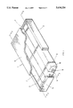
- FIG. 1 is a schematic of a mattress having envelopes constructed in accordance with one preferred embodiment of this invention
- FIG. 2 is a cross-section taken through a side view of said mattress on lines 2--2 in FIG. 1;
- FIG. 3 is a cross-sectional detail of an envelope and the intake and exhaust valves taken along lines 3--3 in FIG. 1;
- FIG. 4 is an cross-sectional end view of a envelope taken along lines 4--4 in FIG. 3;
- FIG. 5 is a plan view of a mattress having envelopes constructed in accordance with this invention.
- FIG. 6 is a detail of a side view of an envelope constructed in accordance with another preferred embodiment of this invention.
- FIG. 7 is a schematic view of a cushion having envelopes constructed in accordance with a third preferred embodiment of this invention.
- FIG. 8 is a cross-section through a side view of said cushion.
- FIG. 9 is a cross-section through an end view of said cushion.
- a mattress (1) comprises two side walls (2) and (3) and two end walls (4) and (5), a resilient cover (6) and envelopes (7) connected by bands (8).
- the particular construction of the mattress (1) shown in FIG. 1 is not essential to this invention but is illustrative of a use of the invention.
- Each envelope (7) has an intake and exhaust valves (9) and (10) respectively connected to a common pipe (11 ) in communication with the interior of the envelope (7).
- Each intake valve (9) may be a simple one way or check valve that permits air or other fluid to flow in one direction, namely into the interior of the envelope (7).
- Each exhaust valve (10) is a relief valve that permits exhaust to flow from the envelope (7) when pressure within the envelope exceeds the release pressure of the exhaust valve (12).
- an exhaust valve (12) has a pressure regulator which permits one to preset the release pressure.
- the envelopes of this preferred embodiment contain a resilient substance (12) which is deformable as load is applied but which will spring back to its original shape as the load is removed. As it returns to its original shape, it presses against the interior wall of the envelope to create a partial vacuum to draw fluid into the intake valve (9).
- the envelope may be loose fitting (see FIG. 3) or snug (see FIG. 6) about the resilient substance (12).
- the resilient substance (12) is coated with an envelope forming material. It is desirable that the resilient substance (12) should be permeable to the passage of the fluid to facilitate exhaustion and refilling of the envelope.
- suitable fabrication materials from a wide array of conventional materials. Examples of such materials, not intended to be limiting, include polyethylene for envelopes, polyurethane foam for resilient material and air for a fluid.
- the fluid used in the envelopes is preferably a compressible fluid but could be non-compressible as well. Air is preferred since it can be exhausted into and drawn from the surrounding environment which provides a convenient reservoir. If other fluids are used, it will be appreciated that a reservoir will be required in communication with the intake and exhaust valves. It will also be appreciated that two reservoirs may be provided; one for intake and one for exhaust. If separate intake and exhaust reservoirs are used, each reservoir pressure may be preset to assist in pressure regulation of the envelope (7).
- the resilient material (12) may be shaped to provide an increasing area to the load as its sinks into the material.
- the resilient material (12) may be shaped to provide more resistance as the load sinks which reduces the amount of the load available to increase fluid pressure in the envelope (7). It is preferred that the resilient material (12) have the shape of a truncated pyramid as shown in FIGS. 3 and 6 for this purpose. It will be appreciated that other shapes, such as cones will also be suitable for this purpose.
- the envelope of this invention will deform under load while exhausting fluid until equilibrium is achieved in the forces of the load, the fluid pressure and the resilient material.
- Pressure within the envelope (7) is maintained below a release pressure of the exhaust valve (10) and the release pressure is set to allow the load to sink into an envelope (7) by a desired amount.
- the pressure regulation feature of the exhaust valve permits a release pressure to be preset to accommodate a particular load or a range of anticipated loads.
- different envelopes (7) may have exhaust valves (10) set at different release pressures.
- the bed (1) may be adapted to have certain envelopes (7) which will support a patient at a lower level and others at a higher level.
- the envelopes (7) may be set with higher levels of support near the sides to resist the tendency of a patient to roll accidentally out of bed or the envelopes (7) may be set to assist a patient to roll over from an existing position to a different position to relieve sores or to present an area for treatment. Active control of intake and exhaust pressures can facilitate more active control of the patient. Other such uses of this invention will become apparent to those skilled in the art.
- FIGS. 7-9 illustrates a seat cushion constructed to take advantage of this invention.
- a cushion (20) is made up of three envelopes (21), (22) and (23) which are filled with a resilient material (24).
- One or more intake and exhaust valves (25) may be provided depending on the construction desired.
- Each intake and exhaust valve (25) has the features described above in that it will intake fluid at ambient conditions and exhaust at a predetermined release pressure.
- the envelopes (21), (22) and (23) may be in communication as shown or form separate chambers having their own valves (25).
- the envelopes (21), (22) and (23) will have a common release pressure, therefore resistance to loading in each envelope will depend on the thickness and resilience of the resilient material within them. In the latter configuration, the resistance to loading will also depend on individual pressure settings of a exhaust valve (25) in each envelope.
Abstract
Description
Claims (27)
Priority Applications (6)
| Application Number | Priority Date | Filing Date | Title |
|---|---|---|---|
| US08/291,551 US5634224A (en) | 1994-08-16 | 1994-08-16 | Inflatable cushioning device with self opening intake valve |
| CA002197434A CA2197434C (en) | 1994-08-16 | 1995-08-15 | Cushioning device |
| JP08507568A JP3038498B2 (en) | 1994-08-16 | 1995-08-15 | Shock absorber |
| PCT/US1995/010333 WO1996004825A1 (en) | 1994-08-16 | 1995-08-15 | Cushioning device |
| AU33257/95A AU686446B2 (en) | 1994-08-16 | 1995-08-15 | Cushioning device |
| EP95929528A EP0776172A1 (en) | 1994-08-16 | 1995-08-15 | Cushioning device |
Applications Claiming Priority (1)
| Application Number | Priority Date | Filing Date | Title |
|---|---|---|---|
| US08/291,551 US5634224A (en) | 1994-08-16 | 1994-08-16 | Inflatable cushioning device with self opening intake valve |
Publications (1)
| Publication Number | Publication Date |
|---|---|
| US5634224A true US5634224A (en) | 1997-06-03 |
Family
ID=23120770
Family Applications (1)
| Application Number | Title | Priority Date | Filing Date |
|---|---|---|---|
| US08/291,551 Expired - Lifetime US5634224A (en) | 1994-08-16 | 1994-08-16 | Inflatable cushioning device with self opening intake valve |
Country Status (6)
| Country | Link |
|---|---|
| US (1) | US5634224A (en) |
| EP (1) | EP0776172A1 (en) |
| JP (1) | JP3038498B2 (en) |
| AU (1) | AU686446B2 (en) |
| CA (1) | CA2197434C (en) |
| WO (1) | WO1996004825A1 (en) |
Cited By (54)
| Publication number | Priority date | Publication date | Assignee | Title |
|---|---|---|---|---|
| WO1998030133A1 (en) * | 1997-01-10 | 1998-07-16 | Comfortex Health Care Surfaces | Pressure reducing cushion with selective pressure point relief |
| US5797155A (en) * | 1996-06-07 | 1998-08-25 | Span-America Medical Systems, Inc. | Wheelchair cushion with protectively encased self-adjusting reservoir means |
| US5974608A (en) * | 1998-06-01 | 1999-11-02 | Stearns, Inc. | Camping mattress with cradling cushions |
| US6012188A (en) * | 1996-03-13 | 2000-01-11 | Ooltewah Manufacturing Company | Selectively deformable cushion |
| WO2000062648A1 (en) * | 1999-04-20 | 2000-10-26 | M.P.L. Ltd. | Inflatable cushioning device with manifold system |
| US6349439B1 (en) * | 1996-12-04 | 2002-02-26 | Huntleigh Technology, Plc | Alternating pad |
| US6370716B1 (en) | 1999-04-20 | 2002-04-16 | John W. Wilkinson | Inflatable cushioning device with tilting apparatus |
| US6385804B1 (en) * | 1998-07-30 | 2002-05-14 | Huntleigh Technology, Plc | Pressure control led pad |
| WO2002102195A2 (en) * | 2001-06-15 | 2002-12-27 | Hon Technology Inc. | Body support system |
| US6564411B2 (en) | 2001-03-19 | 2003-05-20 | Shahzad Pirzada | Active fluid channeling system for a bed |
| US20030096685A1 (en) * | 2001-11-16 | 2003-05-22 | Bernard Weitzman | Exercise apparatus and method |
| US20030191437A1 (en) * | 2000-06-30 | 2003-10-09 | Embro Corporation | Therapeutic device and system |
| US20030208848A1 (en) * | 2002-02-28 | 2003-11-13 | Flick Roland E. | Self-adjusting cushioning device |
| US6673028B1 (en) * | 1996-09-26 | 2004-01-06 | Wake Forest University Health Sciences | Passive joint movement device and method for using the same |
| US6684433B2 (en) * | 2001-03-07 | 2004-02-03 | Gualtiero G. Giori | Pressure adjustable foam support apparatus |
| US6694556B2 (en) | 2001-02-15 | 2004-02-24 | Hill-Rom Services, Inc. | Self-inflating mattress |
| US6711771B2 (en) * | 1999-05-03 | 2004-03-30 | Huntleigh Technology Plc | Alternating pad |
| US6739009B2 (en) * | 2000-05-26 | 2004-05-25 | Del Drago Marcantonio | Supporting device, notably mattress, mattress support or for a seat |
| US6789284B2 (en) | 2000-12-09 | 2004-09-14 | Huntleigh Technology, Plc | Inflatable support |
| US20040222684A1 (en) * | 2002-11-22 | 2004-11-11 | Schukra Of North America | Self inflating pneumatic seat cushion apparatus and method |
| US6839929B2 (en) * | 2001-12-13 | 2005-01-11 | Hill-Rom Services, Inc. | Self-sealing mattress structure |
| KR100466242B1 (en) * | 2002-10-07 | 2005-01-14 | 젠-슈 차이 | Self inflated air cushioned bed |
| US20050090721A1 (en) * | 2001-03-19 | 2005-04-28 | Shahzad Pirzada | Weighing and pump system for a bed |
| US20050125905A1 (en) * | 1999-04-20 | 2005-06-16 | John Wilkinson | Inflatable cushioning device with manifold system |
| US20050177952A1 (en) * | 2004-02-13 | 2005-08-18 | Wilkinson John W. | Discrete cell body support and method for using the same to provide dynamic massage |
| US20050273941A1 (en) * | 2004-06-04 | 2005-12-15 | Stolpmann James R | Mattress with heel pressure relief portion |
| US20060075569A1 (en) * | 2002-09-17 | 2006-04-13 | Gino Giori | Adjustable foam mattress |
| US20060168735A1 (en) * | 2005-02-02 | 2006-08-03 | Ren-Ji Tsay | Air cushion with selectively deflated chambers |
| US20070113352A1 (en) * | 2005-08-10 | 2007-05-24 | Craig Poulos | Therapeutic mattress |
| US20070155208A1 (en) * | 2006-01-03 | 2007-07-05 | Shahzad Pirzada | System, device and process for remotely controlling a medical device |
| US7698765B2 (en) | 2004-04-30 | 2010-04-20 | Hill-Rom Services, Inc. | Patient support |
| US20100146709A1 (en) * | 2008-12-17 | 2010-06-17 | Stryker Corporation | Patient support |
| US20100180384A1 (en) * | 2005-03-28 | 2010-07-22 | B.G. Industries, Inc. | Mattress |
| US20140101861A1 (en) * | 2012-10-15 | 2014-04-17 | Kap Medical, Inc. | Patient support appratus and method |
| WO2014063132A1 (en) * | 2012-10-19 | 2014-04-24 | Wilkinson Jeffrey W | Cushioning device and method of cushioning a body |
| US8745788B2 (en) | 2005-07-26 | 2014-06-10 | Hill-Rom Services. Inc. | System and method for controlling an air mattress |
| US8789224B2 (en) | 2000-11-07 | 2014-07-29 | Tempur-Pedic Managemant, LLC | Therapeutic mattress assembly |
| US20140215724A1 (en) * | 2009-10-02 | 2014-08-07 | Sizewise Rentals, L.L.C. | Segmented air foam mattress |
| US20150061346A1 (en) * | 2013-09-05 | 2015-03-05 | Heavy Feather, Llc | Cushions for relieving sciatic and/or perineum pressure |
| US8973186B2 (en) | 2011-12-08 | 2015-03-10 | Hill-Rom Services, Inc. | Optimization of the operation of a patient-support apparatus based on patient response |
| US20150320230A1 (en) * | 2014-05-09 | 2015-11-12 | Dreamwell, Ltd. | Firmness control for a smart response technology body support |
| WO2016040282A1 (en) * | 2014-09-08 | 2016-03-17 | Wcw, Inc. | Cushioning device and method of cushioning a body |
| GB2536637A (en) * | 2015-03-23 | 2016-09-28 | Talar-Made Ltd | An apparatus and method for supporting at least a part of a person and a method of manufacturing an apparatus |
| US20170112674A1 (en) * | 2015-10-27 | 2017-04-27 | Hill-Rom Services, Inc. | Dressing and Dressing Assembly for Preventing Pressure Ulcers |
| US9820904B2 (en) | 2011-07-13 | 2017-11-21 | Stryker Corporation | Patient/invalid handling support |
| US10182954B2 (en) * | 2014-09-08 | 2019-01-22 | Wcw, Inc. | Cushioning device and method |
| US11033117B2 (en) | 2017-07-27 | 2021-06-15 | Hill-Rom Services, Inc. | Dynamic foam mattress adapted for use with a variable length hospital bed |
| US20210275371A1 (en) * | 2012-04-12 | 2021-09-09 | Sage Products, Llc | Apparatus and method for positioning a seated patient |
| US11191367B2 (en) * | 2016-08-21 | 2021-12-07 | Mobisafe Systems Inc. | Inflatable cellular cushioning device for body support |
| US11389120B2 (en) * | 2019-05-30 | 2022-07-19 | Hill-Rom Services, Inc. | Mattress having selectable patient weight valve, inductive power, and a digital x-ray cassette |
| EP4066690A1 (en) | 2021-03-30 | 2022-10-05 | Invacare International GmbH | Pressure redistribution mattress |
| US11540964B2 (en) | 2018-02-27 | 2023-01-03 | Hill-Rom Services, Inc. | Patient support surface control, end of life indication, and x-ray cassette sleeve |
| RU2793885C1 (en) * | 2022-05-05 | 2023-04-07 | Михаил Григорьевич Рыжиков | Medical mattress for changing position of a patient with reduced mobility from a position on the left side to position on the back, to the right side and backwards during medical procedures and service |
| US11672356B2 (en) * | 2017-03-24 | 2023-06-13 | Comfort Concepts Pty Limited | Seating cushion |
Families Citing this family (6)
| Publication number | Priority date | Publication date | Assignee | Title |
|---|---|---|---|---|
| NL1007398C2 (en) * | 1997-08-07 | 1999-02-09 | Patrick Kloppenborg | Conforming body support with air chamber and pump chamber. |
| IES81179B2 (en) * | 1998-12-03 | 2000-06-14 | Longhaul Tech R & D Ltd | A seat |
| EP2431081B1 (en) | 2010-09-17 | 2014-11-05 | Österreichischer Skiverband | Heel guide of a ski binding |
| AT511783A1 (en) | 2011-07-28 | 2013-02-15 | Christoph Axel Dipl Ing | INFLATABLE BODY WITH A AIR-SEALED OUTER SLEEVE |
| WO2013136386A1 (en) * | 2012-03-15 | 2013-09-19 | 東海ゴム工業株式会社 | Alternating pressure mattress |
| KR101529134B1 (en) * | 2013-08-27 | 2015-06-16 | 함의신 | Cushion imbedded self inflated air tube and method for manufacturing the same |
Citations (10)
| Publication number | Priority date | Publication date | Assignee | Title |
|---|---|---|---|---|
| US201728A (en) * | 1878-03-26 | Improvement in combined bed and life-raft | ||
| US2750606A (en) * | 1953-05-14 | 1956-06-19 | Dayton Rubber Company | Foam rubber pillow construction |
| US4477935A (en) * | 1982-01-08 | 1984-10-23 | Griffin Gordon D | Mattress support system |
| US4644597A (en) * | 1983-05-09 | 1987-02-24 | Dynatech, Inc. | Air mattress with pressure relief valve |
| US4908895A (en) * | 1989-03-20 | 1990-03-20 | Walker Robert A | Air mattress |
| US4989283A (en) * | 1989-06-12 | 1991-02-05 | Research Development Foundation | Inflation control for air supports |
| US5020176A (en) * | 1989-10-20 | 1991-06-04 | Angel Echevarria Co., Inc. | Control system for fluid-filled beds |
| US5033133A (en) * | 1990-09-13 | 1991-07-23 | Nissen Sports Academy, Inc. | Seat cushion |
| US5070560A (en) * | 1990-10-22 | 1991-12-10 | Healthflex, Inc. | Pressure relief support system for a mattress |
| US5142717A (en) * | 1988-10-20 | 1992-09-01 | Sustena, Inc. | Constant pressure load bearing air chamber |
-
1994
- 1994-08-16 US US08/291,551 patent/US5634224A/en not_active Expired - Lifetime
-
1995
- 1995-08-15 CA CA002197434A patent/CA2197434C/en not_active Expired - Lifetime
- 1995-08-15 JP JP08507568A patent/JP3038498B2/en not_active Expired - Lifetime
- 1995-08-15 EP EP95929528A patent/EP0776172A1/en not_active Withdrawn
- 1995-08-15 WO PCT/US1995/010333 patent/WO1996004825A1/en not_active Application Discontinuation
- 1995-08-15 AU AU33257/95A patent/AU686446B2/en not_active Expired
Patent Citations (10)
| Publication number | Priority date | Publication date | Assignee | Title |
|---|---|---|---|---|
| US201728A (en) * | 1878-03-26 | Improvement in combined bed and life-raft | ||
| US2750606A (en) * | 1953-05-14 | 1956-06-19 | Dayton Rubber Company | Foam rubber pillow construction |
| US4477935A (en) * | 1982-01-08 | 1984-10-23 | Griffin Gordon D | Mattress support system |
| US4644597A (en) * | 1983-05-09 | 1987-02-24 | Dynatech, Inc. | Air mattress with pressure relief valve |
| US5142717A (en) * | 1988-10-20 | 1992-09-01 | Sustena, Inc. | Constant pressure load bearing air chamber |
| US4908895A (en) * | 1989-03-20 | 1990-03-20 | Walker Robert A | Air mattress |
| US4989283A (en) * | 1989-06-12 | 1991-02-05 | Research Development Foundation | Inflation control for air supports |
| US5020176A (en) * | 1989-10-20 | 1991-06-04 | Angel Echevarria Co., Inc. | Control system for fluid-filled beds |
| US5033133A (en) * | 1990-09-13 | 1991-07-23 | Nissen Sports Academy, Inc. | Seat cushion |
| US5070560A (en) * | 1990-10-22 | 1991-12-10 | Healthflex, Inc. | Pressure relief support system for a mattress |
Cited By (105)
| Publication number | Priority date | Publication date | Assignee | Title |
|---|---|---|---|---|
| US6012188A (en) * | 1996-03-13 | 2000-01-11 | Ooltewah Manufacturing Company | Selectively deformable cushion |
| US5797155A (en) * | 1996-06-07 | 1998-08-25 | Span-America Medical Systems, Inc. | Wheelchair cushion with protectively encased self-adjusting reservoir means |
| US6673028B1 (en) * | 1996-09-26 | 2004-01-06 | Wake Forest University Health Sciences | Passive joint movement device and method for using the same |
| US6349439B1 (en) * | 1996-12-04 | 2002-02-26 | Huntleigh Technology, Plc | Alternating pad |
| US5893184A (en) * | 1997-01-10 | 1999-04-13 | Comfortex Health Care Surfaces | Pressure reducing backrest cushion with selective pressure point relief |
| WO1998030133A1 (en) * | 1997-01-10 | 1998-07-16 | Comfortex Health Care Surfaces | Pressure reducing cushion with selective pressure point relief |
| US6209159B1 (en) * | 1997-01-10 | 2001-04-03 | Comfortex Health Care Surfaces | Pressure reducing cushion with selective pressure point relief |
| US5974608A (en) * | 1998-06-01 | 1999-11-02 | Stearns, Inc. | Camping mattress with cradling cushions |
| US6385804B1 (en) * | 1998-07-30 | 2002-05-14 | Huntleigh Technology, Plc | Pressure control led pad |
| US20030208849A1 (en) * | 1999-04-20 | 2003-11-13 | Wilkinson John W. | Inflatable cushioning device with manifold system |
| US10357114B2 (en) * | 1999-04-20 | 2019-07-23 | Wcw, Inc. | Inflatable cushioning device with manifold system |
| US20050125905A1 (en) * | 1999-04-20 | 2005-06-16 | John Wilkinson | Inflatable cushioning device with manifold system |
| AU779556B2 (en) * | 1999-04-20 | 2005-01-27 | Wcw Inc. | Inflatable cushioning device with manifold system |
| US6370716B1 (en) | 1999-04-20 | 2002-04-16 | John W. Wilkinson | Inflatable cushioning device with tilting apparatus |
| US8122545B2 (en) * | 1999-04-20 | 2012-02-28 | M.P.L. Limited | Inflatable cushioning device with manifold system |
| US6826795B2 (en) * | 1999-04-20 | 2004-12-07 | M.P.L. Limited | Inflatable cushioning device with manifold system |
| US6269505B1 (en) * | 1999-04-20 | 2001-08-07 | M.P.L. Ltd. | Inflatable cushioning device with manifold system |
| USRE44584E1 (en) * | 1999-04-20 | 2013-11-12 | M.P.L. Limited | Inflatable cushioning device with manifold system |
| WO2000062648A1 (en) * | 1999-04-20 | 2000-10-26 | M.P.L. Ltd. | Inflatable cushioning device with manifold system |
| US6711771B2 (en) * | 1999-05-03 | 2004-03-30 | Huntleigh Technology Plc | Alternating pad |
| US6739009B2 (en) * | 2000-05-26 | 2004-05-25 | Del Drago Marcantonio | Supporting device, notably mattress, mattress support or for a seat |
| US7396345B2 (en) * | 2000-06-30 | 2008-07-08 | Embro Corporation | Therapeutic device and system |
| US7691084B2 (en) | 2000-06-30 | 2010-04-06 | Embro Corporation | Therapeutic device and system |
| US20030191437A1 (en) * | 2000-06-30 | 2003-10-09 | Embro Corporation | Therapeutic device and system |
| US8789224B2 (en) | 2000-11-07 | 2014-07-29 | Tempur-Pedic Managemant, LLC | Therapeutic mattress assembly |
| US6789284B2 (en) | 2000-12-09 | 2004-09-14 | Huntleigh Technology, Plc | Inflatable support |
| US6694556B2 (en) | 2001-02-15 | 2004-02-24 | Hill-Rom Services, Inc. | Self-inflating mattress |
| US6684433B2 (en) * | 2001-03-07 | 2004-02-03 | Gualtiero G. Giori | Pressure adjustable foam support apparatus |
| US20050090721A1 (en) * | 2001-03-19 | 2005-04-28 | Shahzad Pirzada | Weighing and pump system for a bed |
| US6564411B2 (en) | 2001-03-19 | 2003-05-20 | Shahzad Pirzada | Active fluid channeling system for a bed |
| WO2002102195A3 (en) * | 2001-06-15 | 2004-09-16 | Hon Tech Inc | Body support system |
| US6687933B2 (en) * | 2001-06-15 | 2004-02-10 | Hon Technology, Inc. | Body support system with energy dissipation means |
| GB2392382B (en) * | 2001-06-15 | 2006-01-11 | Hon Tech Inc | Body support system |
| WO2002102195A2 (en) * | 2001-06-15 | 2002-12-27 | Hon Technology Inc. | Body support system |
| US20050005363A1 (en) * | 2001-10-30 | 2005-01-13 | Gualtiero Giori | Pressure adjustable foam support apparatus |
| US20030096685A1 (en) * | 2001-11-16 | 2003-05-22 | Bernard Weitzman | Exercise apparatus and method |
| US7074166B2 (en) * | 2001-11-16 | 2006-07-11 | Bernard Weitzman | Exercise apparatus and method |
| US6839929B2 (en) * | 2001-12-13 | 2005-01-11 | Hill-Rom Services, Inc. | Self-sealing mattress structure |
| US20030208848A1 (en) * | 2002-02-28 | 2003-11-13 | Flick Roland E. | Self-adjusting cushioning device |
| US6813790B2 (en) | 2002-02-28 | 2004-11-09 | Gaymar Industries, Inc. | Self-adjusting cushioning device |
| US20060075569A1 (en) * | 2002-09-17 | 2006-04-13 | Gino Giori | Adjustable foam mattress |
| KR100466242B1 (en) * | 2002-10-07 | 2005-01-14 | 젠-슈 차이 | Self inflated air cushioned bed |
| US6912748B2 (en) | 2002-11-22 | 2005-07-05 | L & P Property Management Company | Self inflating pneumatic seat cushion apparatus and method |
| US20040222684A1 (en) * | 2002-11-22 | 2004-11-11 | Schukra Of North America | Self inflating pneumatic seat cushion apparatus and method |
| US7434283B2 (en) | 2004-02-13 | 2008-10-14 | M.P.L. Limited | Discrete cell body support and method for using the same to provide dynamic massage |
| US20050177952A1 (en) * | 2004-02-13 | 2005-08-18 | Wilkinson John W. | Discrete cell body support and method for using the same to provide dynamic massage |
| US7698765B2 (en) | 2004-04-30 | 2010-04-20 | Hill-Rom Services, Inc. | Patient support |
| US8146191B2 (en) | 2004-04-30 | 2012-04-03 | Hill-Rom Services, Inc. | Patient support |
| US7685664B2 (en) | 2004-06-04 | 2010-03-30 | Hill-Rom Services, Inc. | Mattress with heel pressure relief portion |
| US20050273941A1 (en) * | 2004-06-04 | 2005-12-15 | Stolpmann James R | Mattress with heel pressure relief portion |
| US20060175097A1 (en) * | 2004-09-13 | 2006-08-10 | Shazad Pirzada | Wireless weighing system for a bed |
| CN101123901B (en) * | 2005-01-24 | 2011-05-11 | Mpl有限公司 | Inflatable cushioning device with manifold system |
| WO2006079059A1 (en) * | 2005-01-24 | 2006-07-27 | Mpl, Ltd. | Inflatable cushioning device with manifold system |
| US20060168735A1 (en) * | 2005-02-02 | 2006-08-03 | Ren-Ji Tsay | Air cushion with selectively deflated chambers |
| US7086104B1 (en) * | 2005-02-02 | 2006-08-08 | Ren-Ji Tsay | Air cushion with selectively deflated chambers |
| US20100180384A1 (en) * | 2005-03-28 | 2010-07-22 | B.G. Industries, Inc. | Mattress |
| US7886386B2 (en) * | 2005-03-28 | 2011-02-15 | Bg Industries, Llc. | Mattress |
| US8745788B2 (en) | 2005-07-26 | 2014-06-10 | Hill-Rom Services. Inc. | System and method for controlling an air mattress |
| US20090183313A1 (en) * | 2005-08-10 | 2009-07-23 | Craig Poulos | Therapeutic mattress |
| US20080115288A1 (en) * | 2005-08-10 | 2008-05-22 | Craig Poulos | Therapeutic mattress |
| US20070113352A1 (en) * | 2005-08-10 | 2007-05-24 | Craig Poulos | Therapeutic mattress |
| US7716766B2 (en) | 2005-08-10 | 2010-05-18 | Kreg Medical, Inc. | Therapeutic mattress |
| US20110163885A1 (en) * | 2005-08-10 | 2011-07-07 | Craig Poulos | Adjustable therapeutic mattress |
| US20100000020A1 (en) * | 2005-08-10 | 2010-01-07 | Craig Poulos | Dynamic therapy bed system |
| US7536739B2 (en) | 2005-08-10 | 2009-05-26 | Kreg Medical, Inc. | Therapeutic mattress |
| US7509698B2 (en) | 2005-08-10 | 2009-03-31 | Kreg Medical, Inc. | Therapeutic mattress |
| US8015972B2 (en) | 2006-01-03 | 2011-09-13 | Shahzad Pirzada | System, device and process for remotely controlling a medical device |
| US9278183B2 (en) | 2006-01-03 | 2016-03-08 | Shahzad Pirzada | System, device and process for remotely controlling a medical device |
| US20070155208A1 (en) * | 2006-01-03 | 2007-07-05 | Shahzad Pirzada | System, device and process for remotely controlling a medical device |
| US20100175196A1 (en) * | 2008-12-17 | 2010-07-15 | Patrick Lafleche | Patient support |
| US8910334B2 (en) | 2008-12-17 | 2014-12-16 | Stryker Corporation | Patient support |
| US20100146709A1 (en) * | 2008-12-17 | 2010-06-17 | Stryker Corporation | Patient support |
| US10835050B2 (en) | 2009-10-02 | 2020-11-17 | Sizewise Rentals, L.L.C. | Segmented air mattress with variable stiffness insert |
| US20140215724A1 (en) * | 2009-10-02 | 2014-08-07 | Sizewise Rentals, L.L.C. | Segmented air foam mattress |
| US9877590B2 (en) * | 2009-10-02 | 2018-01-30 | Sizewise Rentals, L.L.C. | Segmented air foam mattress |
| US10987265B2 (en) | 2011-07-13 | 2021-04-27 | Stryker Corporation | Patient/invalid handling support |
| US9820904B2 (en) | 2011-07-13 | 2017-11-21 | Stryker Corporation | Patient/invalid handling support |
| US10391009B2 (en) | 2011-12-08 | 2019-08-27 | Hill-Rom Services, Inc. | Optimization of the operation of a patient-support apparatus based on patient response |
| US8973186B2 (en) | 2011-12-08 | 2015-03-10 | Hill-Rom Services, Inc. | Optimization of the operation of a patient-support apparatus based on patient response |
| US20210275371A1 (en) * | 2012-04-12 | 2021-09-09 | Sage Products, Llc | Apparatus and method for positioning a seated patient |
| US20140101861A1 (en) * | 2012-10-15 | 2014-04-17 | Kap Medical, Inc. | Patient support appratus and method |
| US11020299B2 (en) | 2012-10-15 | 2021-06-01 | Kap Medical, Inc. | Patient support apparatus and method |
| US11679048B2 (en) | 2012-10-15 | 2023-06-20 | Kap Medical, Inc. | Patient support apparatus and method |
| US20150143636A1 (en) * | 2012-10-19 | 2015-05-28 | Jeffrey W. Wilkinson | Cushioning device and method of cushioning a body |
| RU2635907C2 (en) * | 2012-10-19 | 2017-11-16 | Джеффри В. УИЛКИНСОН | Shock absorber and method for body shock absorbtion |
| US9826842B2 (en) * | 2012-10-19 | 2017-11-28 | Jeffrey W. Wilkinson | Cushioning device and method of cushioning a body |
| WO2014063132A1 (en) * | 2012-10-19 | 2014-04-24 | Wilkinson Jeffrey W | Cushioning device and method of cushioning a body |
| US8943627B2 (en) * | 2012-10-19 | 2015-02-03 | Jeffrey W. Wilkinson | Cushioning device and method of cushioning a body |
| US9468299B2 (en) * | 2013-09-05 | 2016-10-18 | Heavy Feather, Llc | Cushions for relieving sciatic and/or perineum pressure |
| US20150061346A1 (en) * | 2013-09-05 | 2015-03-05 | Heavy Feather, Llc | Cushions for relieving sciatic and/or perineum pressure |
| US10548410B2 (en) * | 2014-05-09 | 2020-02-04 | Dreamwell, Ltd. | Firmness control for a smart response technology body support |
| US20150320230A1 (en) * | 2014-05-09 | 2015-11-12 | Dreamwell, Ltd. | Firmness control for a smart response technology body support |
| US10182954B2 (en) * | 2014-09-08 | 2019-01-22 | Wcw, Inc. | Cushioning device and method |
| WO2016040282A1 (en) * | 2014-09-08 | 2016-03-17 | Wcw, Inc. | Cushioning device and method of cushioning a body |
| GB2536637A (en) * | 2015-03-23 | 2016-09-28 | Talar-Made Ltd | An apparatus and method for supporting at least a part of a person and a method of manufacturing an apparatus |
| US20170112674A1 (en) * | 2015-10-27 | 2017-04-27 | Hill-Rom Services, Inc. | Dressing and Dressing Assembly for Preventing Pressure Ulcers |
| US11191367B2 (en) * | 2016-08-21 | 2021-12-07 | Mobisafe Systems Inc. | Inflatable cellular cushioning device for body support |
| US11672356B2 (en) * | 2017-03-24 | 2023-06-13 | Comfort Concepts Pty Limited | Seating cushion |
| US11033117B2 (en) | 2017-07-27 | 2021-06-15 | Hill-Rom Services, Inc. | Dynamic foam mattress adapted for use with a variable length hospital bed |
| US11540964B2 (en) | 2018-02-27 | 2023-01-03 | Hill-Rom Services, Inc. | Patient support surface control, end of life indication, and x-ray cassette sleeve |
| US11389120B2 (en) * | 2019-05-30 | 2022-07-19 | Hill-Rom Services, Inc. | Mattress having selectable patient weight valve, inductive power, and a digital x-ray cassette |
| US11826185B2 (en) | 2019-05-30 | 2023-11-28 | Hill-Rom Services, Inc. | Mattress having selectable patient weight valve, inductive power, and a digital x-ray cassette |
| WO2022208207A1 (en) | 2021-03-30 | 2022-10-06 | Invacare International Gmbh | Pressure redistribution mattress |
| EP4066690A1 (en) | 2021-03-30 | 2022-10-05 | Invacare International GmbH | Pressure redistribution mattress |
| RU2793885C1 (en) * | 2022-05-05 | 2023-04-07 | Михаил Григорьевич Рыжиков | Medical mattress for changing position of a patient with reduced mobility from a position on the left side to position on the back, to the right side and backwards during medical procedures and service |
Also Published As
| Publication number | Publication date |
|---|---|
| JPH10502850A (en) | 1998-03-17 |
| AU686446B2 (en) | 1998-02-05 |
| WO1996004825A1 (en) | 1996-02-22 |
| CA2197434A1 (en) | 1996-02-22 |
| AU3325795A (en) | 1996-03-07 |
| JP3038498B2 (en) | 2000-05-08 |
| EP0776172A1 (en) | 1997-06-04 |
| CA2197434C (en) | 2006-04-25 |
Similar Documents
| Publication | Publication Date | Title |
|---|---|---|
| US5634224A (en) | Inflatable cushioning device with self opening intake valve | |
| US5282286A (en) | Sealed composite cushion having multiple indentation force deflection zones | |
| US7434283B2 (en) | Discrete cell body support and method for using the same to provide dynamic massage | |
| US6148461A (en) | Inflatable support | |
| US6209159B1 (en) | Pressure reducing cushion with selective pressure point relief | |
| US6694556B2 (en) | Self-inflating mattress | |
| JP3959116B2 (en) | Steady pressure seat system | |
| US20080028534A1 (en) | Mattress having three separate adjustable pressure relief zones | |
| EP1845823B1 (en) | Inflatable cushioning device with manifold system | |
| US6813790B2 (en) | Self-adjusting cushioning device | |
| US6519797B1 (en) | Self adjusting, contouring cushioning system | |
| EP1178746B1 (en) | Inflatable cushioning device with manifold system | |
| US4995124A (en) | Constant pressure load bearing air chamber | |
| US20070107133A1 (en) | Air-permeable mattress providing great lying comfort | |
| JP2014018671A (en) | Pressure sore preventing cushion enabling pressure adjustment | |
| US10537185B2 (en) | Accelerated calibration system for a smart response technology mattress | |
| US6126152A (en) | Variable response pneumatic support | |
| US6941602B2 (en) | Self adjusting, contouring cushioning system | |
| US20190307259A1 (en) | Hybrid air immersion mattress | |
| JPS60150713A (en) | Bed | |
| US20070056113A1 (en) | Water pad | |
| CN218219801U (en) | Intelligent pillow capable of being adjusted according to sleeping posture | |
| US20170020769A1 (en) | Cushion support insert | |
| IT202100015518A1 (en) | PADDING FOR SUPPORTING DEVICES | |
| JPH05285028A (en) | Fluid enclosed bed |
Legal Events
| Date | Code | Title | Description |
|---|---|---|---|
| STCF | Information on status: patent grant |
Free format text: PATENTED CASE |
|
| AS | Assignment |
Owner name: M.P.L. LTD., BAHAMAS Free format text: ASSIGNMENT OF ASSIGNORS INTEREST;ASSIGNOR:GATES, STEPHEN M.;REEL/FRAME:008859/0636 Effective date: 19970113 |
|
| REMI | Maintenance fee reminder mailed | ||
| FPAY | Fee payment |
Year of fee payment: 4 |
|
| SULP | Surcharge for late payment | ||
| AS | Assignment |
Owner name: M.P.L. LIMITED, BELIZE Free format text: ASSIGNMENT OF ASSIGNORS INTEREST;ASSIGNOR:M.P.L. LIMITED;REEL/FRAME:013130/0033 Effective date: 20010518 |
|
| FPAY | Fee payment |
Year of fee payment: 8 |
|
| AS | Assignment |
Owner name: MPL LTD., BAHAMAS Free format text: NOTICE OF PENDENCY OF OWNERSHIP DISPUTE (RICO CASE); ROYALTY AND MARKETING AGREEMENT; AFFIDAVIT;ASSIGNOR:GATES, STEPHEN M.;REEL/FRAME:016334/0592 Effective date: 19970113 |
|
| FEPP | Fee payment procedure |
Free format text: PAT HOLDER NO LONGER CLAIMS SMALL ENTITY STATUS, ENTITY STATUS SET TO UNDISCOUNTED (ORIGINAL EVENT CODE: STOL); ENTITY STATUS OF PATENT OWNER: LARGE ENTITY |
|
| FPAY | Fee payment |
Year of fee payment: 12 |