US5631998A - Method for recording and/or reproducing data using a digital video tape - Google Patents
Method for recording and/or reproducing data using a digital video tape Download PDFInfo
- Publication number
- US5631998A US5631998A US08/541,410 US54141095A US5631998A US 5631998 A US5631998 A US 5631998A US 54141095 A US54141095 A US 54141095A US 5631998 A US5631998 A US 5631998A
- Authority
- US
- United States
- Prior art keywords
- trick
- data
- area
- play
- recording
- Prior art date
- Legal status (The legal status is an assumption and is not a legal conclusion. Google has not performed a legal analysis and makes no representation as to the accuracy of the status listed.)
- Expired - Lifetime
Links
Images


Classifications
-
- H—ELECTRICITY
- H04—ELECTRIC COMMUNICATION TECHNIQUE
- H04N—PICTORIAL COMMUNICATION, e.g. TELEVISION
- H04N5/00—Details of television systems
- H04N5/76—Television signal recording
- H04N5/78—Television signal recording using magnetic recording
- H04N5/782—Television signal recording using magnetic recording on tape
- H04N5/783—Adaptations for reproducing at a rate different from the recording rate
-
- G—PHYSICS
- G11—INFORMATION STORAGE
- G11B—INFORMATION STORAGE BASED ON RELATIVE MOVEMENT BETWEEN RECORD CARRIER AND TRANSDUCER
- G11B20/00—Signal processing not specific to the method of recording or reproducing; Circuits therefor
- G11B20/10—Digital recording or reproducing
- G11B20/12—Formatting, e.g. arrangement of data block or words on the record carriers
- G11B20/1201—Formatting, e.g. arrangement of data block or words on the record carriers on tapes
- G11B20/1207—Formatting, e.g. arrangement of data block or words on the record carriers on tapes with transverse tracks only
- G11B20/1208—Formatting, e.g. arrangement of data block or words on the record carriers on tapes with transverse tracks only for continuous data, e.g. digitised analog information signals, pulse code modulated [PCM] data
-
- G—PHYSICS
- G11—INFORMATION STORAGE
- G11B—INFORMATION STORAGE BASED ON RELATIVE MOVEMENT BETWEEN RECORD CARRIER AND TRANSDUCER
- G11B20/00—Signal processing not specific to the method of recording or reproducing; Circuits therefor
- G11B20/10—Digital recording or reproducing
- G11B20/18—Error detection or correction; Testing, e.g. of drop-outs
- G11B20/1806—Pulse code modulation systems for audio signals
- G11B20/1809—Pulse code modulation systems for audio signals by interleaving
-
- H—ELECTRICITY
- H04—ELECTRIC COMMUNICATION TECHNIQUE
- H04N—PICTORIAL COMMUNICATION, e.g. TELEVISION
- H04N5/00—Details of television systems
- H04N5/76—Television signal recording
- H04N5/907—Television signal recording using static stores, e.g. storage tubes or semiconductor memories
-
- H—ELECTRICITY
- H04—ELECTRIC COMMUNICATION TECHNIQUE
- H04N—PICTORIAL COMMUNICATION, e.g. TELEVISION
- H04N9/00—Details of colour television systems
- H04N9/79—Processing of colour television signals in connection with recording
- H04N9/80—Transformation of the television signal for recording, e.g. modulation, frequency changing; Inverse transformation for playback
- H04N9/804—Transformation of the television signal for recording, e.g. modulation, frequency changing; Inverse transformation for playback involving pulse code modulation of the colour picture signal components
- H04N9/8042—Transformation of the television signal for recording, e.g. modulation, frequency changing; Inverse transformation for playback involving pulse code modulation of the colour picture signal components involving data reduction
-
- H—ELECTRICITY
- H04—ELECTRIC COMMUNICATION TECHNIQUE
- H04N—PICTORIAL COMMUNICATION, e.g. TELEVISION
- H04N5/00—Details of television systems
- H04N5/76—Television signal recording
- H04N5/765—Interface circuits between an apparatus for recording and another apparatus
- H04N5/77—Interface circuits between an apparatus for recording and another apparatus between a recording apparatus and a television camera
- H04N5/772—Interface circuits between an apparatus for recording and another apparatus between a recording apparatus and a television camera the recording apparatus and the television camera being placed in the same enclosure
-
- H—ELECTRICITY
- H04—ELECTRIC COMMUNICATION TECHNIQUE
- H04N—PICTORIAL COMMUNICATION, e.g. TELEVISION
- H04N5/00—Details of television systems
- H04N5/76—Television signal recording
- H04N5/78—Television signal recording using magnetic recording
- H04N5/782—Television signal recording using magnetic recording on tape
- H04N5/7824—Television signal recording using magnetic recording on tape with rotating magnetic heads
- H04N5/7826—Television signal recording using magnetic recording on tape with rotating magnetic heads involving helical scanning of the magnetic tape
- H04N5/78263—Television signal recording using magnetic recording on tape with rotating magnetic heads involving helical scanning of the magnetic tape for recording on tracks inclined relative to the direction of movement of the tape
-
- H—ELECTRICITY
- H04—ELECTRIC COMMUNICATION TECHNIQUE
- H04N—PICTORIAL COMMUNICATION, e.g. TELEVISION
- H04N9/00—Details of colour television systems
- H04N9/79—Processing of colour television signals in connection with recording
- H04N9/80—Transformation of the television signal for recording, e.g. modulation, frequency changing; Inverse transformation for playback
- H04N9/82—Transformation of the television signal for recording, e.g. modulation, frequency changing; Inverse transformation for playback the individual colour picture signal components being recorded simultaneously only
- H04N9/8205—Transformation of the television signal for recording, e.g. modulation, frequency changing; Inverse transformation for playback the individual colour picture signal components being recorded simultaneously only involving the multiplexing of an additional signal and the colour video signal
- H04N9/8227—Transformation of the television signal for recording, e.g. modulation, frequency changing; Inverse transformation for playback the individual colour picture signal components being recorded simultaneously only involving the multiplexing of an additional signal and the colour video signal the additional signal being at least another television signal
Definitions
- the present invention relates to a method for recording and/or reproducing data using a digital video tape, and more particularly, to a method for recording and/or reproducing data for performing a trick-play in an apparatus for recording and reproducing an advanced television (ATV) signal using a digital video tape.
- ATV advanced television
- a digital video tape recorder (DVCR) for recording and reproducing an ATV signal on digital video tape of a standard-definition videocassette recorder (SD-VCR) has been developed.
- bit stream for an SD-VCR has a bit rate of 24.9 Mbps
- bit stream for an ATV signal has a bit rate of 19.3 Mbps
- An ongoing study is directed to a method by which trick-play data for performing trick-play operations can be recorded in the above remaining video and audio sector areas in order to satisfy various trick-play speeds and meet the requirements of various kinds of scanners while improving picture quality by reducing noise.
- the present invention proposes a method for recording the trick-play data which enables a broader range of multiple speeds in a trick-play mode at the time of recording or reproducing data for a DVCR.
- the goal in developing DVCRs is to establish a recording format for a specific reproduction which is desirable in terms of picture quality and cost.
- a conventional method exists by which trick-play data is arranged in the scanning area corresponding to each multiple speed. According to this method, the picture quality of a screen reproduced by performing a trick-play operation is relatively good. However, it is essential to scan the trick-play data area in scanning areas corresponding to each multiple speed. Thus, the servo should be controlled with a high degree of precision, which results in a cost increase.
- a method for recording data onto a digital video tape by dividing the ATV signal into normal-play data for performing a normal-play operation and trick-play data for performing a trick-play operation, wherein the ATV signal contains frame data which are supplied in a predetermined interval and can be decoded independently comprising the steps of: dividing the data area of a sync block forming an audio sector and a video sector of each track of the digital video tape into a first area and a second area; recording the normal-play data in the first area and the trick-play data in the second area; and repeatedly recording the same trick-play data in sync blocks of the same number with respect to a number of tracks corresponding to twice the maximum even-multiple speed number among a plurality of even-multiple speeds, when the trick-play data is recorded in the second area.
- a method for recording data onto a digital video tape by dividing the ATV signal into normal-play data for performing a normal-play operation and trick-play data for performing a trick-play operation wherein the ATV signal contains frame data which are supplied in a predetermined interval and can be decoded independently, the method comprising the steps of: dividing the data area of a sync block forming a video sector of each track of the digital video tape into a first area and a second area; recording the normal-play data in the first area and the trick-play data in the second area; and repeatedly recording the same trick-play data in sync blocks of the same number with respect to a number of tracks corresponding to twice the maximum even-multiple speed number among a plurality of even-multiple speeds, when the trick-play data is recorded in the second area.
- a method for recording data onto a digital video tape by dividing the ATV signal into normal-play data for performing a normal-play operation and trick-play data for performing a trick-play operation wherein the ATV signal contains frame data which are supplied in a predetermined interval and can be decoded independently, the method comprising the steps of: dividing the data area of a sync block forming an audio sector of each track of the digital video tape into a first area and a second area; recording the normal-play data in the first area and the trick-play data in the second area; and repeatedly recording the same trick-play data in sync blocks of the same number with respect to a number of tracks corresponding to twice the maximum even-multiple speed number among a plurality of even-multiple speeds, when the trick-play data is recorded in the second area.
- a method for reproducing an ATV signal containing frame data supplied in a predetermined interval and decoded independently by dividing said ATV signal into normal-play data for performing a normal-play operation and trick-play data for performing a trick-play operation and recording said normal-play data and trick-play data respectively in first and second areas of each track of a digital video tape said method comprising the steps of: scanning the data-recorded area of said digital video tape by means of a head; decoding said trick-play data by scanning said first area in which normal-play data is recorded and said second area in which trick-play data is recorded and by scanning an inner parity error correction area; and reproducing said trick-play data by decoding said trick-play data by scanning an outer parity error correction area for said second area.
- FIG. 1 shows a track format of a digital video tape having a recording format of an SD-VCR
- FIGS. 2A to 2C show data sync blocks according to the conventional method and the present invention
- FIGS. 3A and 3B show audio and video sectors of a sync block of data area according to the present invention.
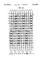
- FIGS. 4A to 4D show trick-play performance according to the present invention.
- normal-play data and trick-play data are recorded separately in different areas in a data area of a sync block, which can be attained by employing as a trick-play data area the 5.6 Mbps bit stream which remains when a 19.3 Mbps ATV bit stream is used as a normal-play data area in the recording bit capacity of a 24.9 Mbps SD-VCR bit stream.
- a track is sequentially divided into an insert and track information (ITI) sector 2, an audio sector 4, a video sector 6 and a subcode sector 8.
- ITI sector 2 consists of ITI pre-amble 10, start-sync block area 12, track information area 14 and ITI post-amble 16.
- Audio sector 4 consists of audio pre-amble 18, fourteen audio data sync blocks 20 and audio post-amble 22.
- Video sector 6 consists of video pre-amble 24, 149 video data sync blocks 26 and video post-amble 28.
- Subcode sector 8 consists of subcode pre-amble 30, subcode area 32 and subcode post-amble 34. The area following the subcode sector 8 corresponds to an overwrite margin 36.
- FIG. 2A shows a conventional data sync block.
- reference numeral 38 denotes a two-byte sync area
- 40 denotes a three-byte identification (ID) code
- 42 denotes a 77-byte data area
- 44 denotes an eight-byte inner parity area.
- FIG. 2B shows a data sync block according to the present invention.
- reference numeral 42 denotes a data area (the same as shown in FIG. 2A), and 46 denotes an area for recording trick-play data having a predetermined size within the data area 42.
- the trick-play data area 46 is shown to occupy seventeen bytes from the 65th byte to the 81st byte within the data area 42 in FIG. 2B, it is not necessarily limited to positions of these bytes and may occupy any seventeen bytes positioned within the data area 42.
- a and B are real numbers.
- the bit rate of the standardized SD-VCR bit stream is 24.9 Mbps and that of the standardized ATV signal bit stream is 19.3 Mbps
- the 5.6 Mbps surplus is used for the trick-play data area. That is to say, if the value of A and/or B is changed, C is also changed accordingly.
- FIG. 2C shows that the trick-play data of the data area is set in a different position from that of FIG. 2B and indicates that the trick-play data can be recorded in any position of the data area 42. Positioning the trick-play data as in FIG. 2C is applicable to both audio and video sectors. However, for the sake of a simplified explanation, only the video sector application will be described. Here, the reference numerals in FIG. 2C are the same as those in FIG. 2B.
- the present invention shows an embodiment for the case when the trick-play data is recorded in the last seventeen bytes of data area 42, as shown in FIG. 2B, which is applied to an audio sector as well as a video sector.
- FIG. 3A shows a video sector of each sync block and corresponds to the case when the trick-play data is positioned as shown in FIG. 2B.
- reference letter i denotes the number of sync blocks with respect to video data
- 48 denotes an area where normal-play data is recorded within the data area
- 50 denotes an area where trick-play data is recorded within the data area.
- FIG. 3B shows a video sector of each sync block of a data area and corresponds to the case when the trick-play data is positioned as shown in FIG. 2C.
- Reference numerals in FIG. 3B are the same as those in FIG. 3A and their explanation will be omitted.
- trick-play data is repeatedly recorded on as many tracks as twice the maximum multiple speed, and then reproduced.
- FIG. 4A shows a status where trick-play data is recorded on as many tracks as twice the maximum multiple speed and corresponds to the case shown in FIG. 3A.
- numerals marked in the ordinate direction represent the number of sync blocks.
- the trick-play data is recorded only in the video data area here, it should be noted that the same effect is applied to the case when the trick-play data is recorded in the audio data area. If the case shown in FIG. 3B is applied to FIG. 4A, the trick-play data of each sync block will be repeatedly recorded somewhere in the mid-section of the sync block, not in the tail end.
- the maximum multiple speed is set as a speed of six times the normal-play speed.
- FIG. 4B shows that a head scans the track whereon trick-play data is recorded at a speed of six times the normal-play speed.
- the number of tracks having trick-play data recorded is twelve.
- the same trick-play data is recorded in each trick-play data area of the same sync block number with respect to twelve tracks.
- the oblique-lined portions are trick-play data areas
- the blackened portions are portions read by heads a and b during their scanning operations for a trick-play operation
- the "white" (blank) portions are normal-play data areas.
- Head a reads tracks of the a portion
- head b reads tracks of the b portion.
- head a decodes sync blocks 23, 24, 25, 26, 153, 154 and 155 and head b decodes sync blocks 21, 22, 150, 151 and 152. That is to say, in the case of a maximum multiple speed of six-times the normal-play speed, the trick-play data is allotted to twelve tracks, to then be scanned by heads a and b.
- the reason is that the difference between the portions scanned by a head for performing a trick-play operation at a speed of 4.0 times and at a speed of 4.1 times is very small in lo the case of a speed of four times the normal-play speed, for example. Also, as described above, if the head reads 50% of the data, the data can be decoded. Thus, the multiple speeds corresponding to the numbers containing a decimal point at which more than 50% of data cannot be read, are not available. Next, according to the embodiment described above, the multiple speeds of four times and two times will be described.
- FIG. 4C shows a scanning of a head when a speed of four times is selected, in the case of a trick-play operation which can be performed at a speed of six times the scanning speed at maximum. Since the same trick-play data is recorded in each trick-play data area of the same sync block number with respect to twelve tracks, head a scans the same data (the dotted-line portions 1 and 2) twice, and head b scans data once.
- FIG. 4D shows a scanning of a head when a two-times speed is selected in the case of a trick-play operation by which the maximum speed of six times can be performed.
- the same data is read three times each, by heads a and b, respectively. That is to say, portions 3, 5 and 7 represent the trick-play data read by head a and portions 4, 6 and 8 represent the trick-play data read by head b. Since the same screens are repeatedly displayed three times by the multiple speed of two times, compared to the multiple speed of six times, it appears comparatively tedious.
- trick-play operations at speeds of 2, 4, 6, . . . , 28 and 30 times are available.
- the reverse-direction multiple speeds corresponding thereto are also available.
- the multiple speeds corresponding to the numbers having a decimal point are available as above-explained. This means that the user's selection becomes remarkably diversified, compared to those in the conventional trick-play system which enables only speeds of a specific multiple.
- ECC error correction coding
- error correction codes follow behind audio and video data areas.
- inner parity is disposed vertically and outer parity is disposed horizontally, both of which perform an ECC.
- an eight-byte inner parity follows a 77-byte data area for a sync block. Also, for a track, the outer parities follow the audio data area in the sync blocks of a predetermined number, and the outer parities of a predetermined number follow the video data area, for performing an ECC.
- the ECC of the trick-play data can be implemented with the ECC area of normal-play data only, which is an essential area. This contributes to a recording efficiency whereby a large quantity of data can be recorded in a given area.
- the area corresponding to 5.6 Mbps is used as trick-play data in the case of an ATV signal. Also, a separate data area is not required for performing ECC of trick-play data. Since the trick-play operation of speeds of even-number multiples are available within the range of the maximum multiple speed, a variety of speeds for a trick-play mode is allowed.
Abstract
A method for performing a trick play in a digital video tape apparatus for recording and/or reproducing an advanced television (ATV) signal is performed such that the data area of a sync block forming an audio sector and a video sector in a track is divided into a first area and a second area to record and reproduce normal-play data and trick-play data for a normal play and a trick play, respectively. The area corresponding to 5.6 Mbps is used for trick-play data in the case of an ATV signal; a separate data area for the error correction coding of a trick-play data is not necessary. Also, since trick plays of speeds of even-number times are available within the range of the maximum multiple speed, a diversity of speeds for a trick-play mode are allowed.
Description
The present invention relates to a method for recording and/or reproducing data using a digital video tape, and more particularly, to a method for recording and/or reproducing data for performing a trick-play in an apparatus for recording and reproducing an advanced television (ATV) signal using a digital video tape.
A digital video tape recorder (DVCR) for recording and reproducing an ATV signal on digital video tape of a standard-definition videocassette recorder (SD-VCR) has been developed. Here, considering that the bit stream for an SD-VCR has a bit rate of 24.9 Mbps and the bit stream for an ATV signal has a bit rate of 19.3 Mbps, an area where bits can be recorded at a rate of 5.6 Mbps remains unused. An ongoing study is directed to a method by which trick-play data for performing trick-play operations can be recorded in the above remaining video and audio sector areas in order to satisfy various trick-play speeds and meet the requirements of various kinds of scanners while improving picture quality by reducing noise.
As a part of this study, the present invention proposes a method for recording the trick-play data which enables a broader range of multiple speeds in a trick-play mode at the time of recording or reproducing data for a DVCR.
The goal in developing DVCRs is to establish a recording format for a specific reproduction which is desirable in terms of picture quality and cost.
A conventional method exists by which trick-play data is arranged in the scanning area corresponding to each multiple speed. According to this method, the picture quality of a screen reproduced by performing a trick-play operation is relatively good. However, it is essential to scan the trick-play data area in scanning areas corresponding to each multiple speed. Thus, the servo should be controlled with a high degree of precision, which results in a cost increase.
In order to solve the above-described problems, it is therefore an object of the present invention to provide a method for recording data onto or reproducing data from a digital video tape whereby the manufacturing cost is reduced and a diversity of multiple speeds are available in performing trick-play operations of a DVCR, since high-precision servo control is not required when a head scans a data-arranged area.
According to one aspect of the present invention, there is provided a method for recording data onto a digital video tape by dividing the ATV signal into normal-play data for performing a normal-play operation and trick-play data for performing a trick-play operation, wherein the ATV signal contains frame data which are supplied in a predetermined interval and can be decoded independently, the method comprising the steps of: dividing the data area of a sync block forming an audio sector and a video sector of each track of the digital video tape into a first area and a second area; recording the normal-play data in the first area and the trick-play data in the second area; and repeatedly recording the same trick-play data in sync blocks of the same number with respect to a number of tracks corresponding to twice the maximum even-multiple speed number among a plurality of even-multiple speeds, when the trick-play data is recorded in the second area.
According to another aspect of the present invention, there is provided a method for recording data onto a digital video tape by dividing the ATV signal into normal-play data for performing a normal-play operation and trick-play data for performing a trick-play operation, wherein the ATV signal contains frame data which are supplied in a predetermined interval and can be decoded independently, the method comprising the steps of: dividing the data area of a sync block forming a video sector of each track of the digital video tape into a first area and a second area; recording the normal-play data in the first area and the trick-play data in the second area; and repeatedly recording the same trick-play data in sync blocks of the same number with respect to a number of tracks corresponding to twice the maximum even-multiple speed number among a plurality of even-multiple speeds, when the trick-play data is recorded in the second area.
According to still another aspect of the present invention, there is provided a method for recording data onto a digital video tape by dividing the ATV signal into normal-play data for performing a normal-play operation and trick-play data for performing a trick-play operation, wherein the ATV signal contains frame data which are supplied in a predetermined interval and can be decoded independently, the method comprising the steps of: dividing the data area of a sync block forming an audio sector of each track of the digital video tape into a first area and a second area; recording the normal-play data in the first area and the trick-play data in the second area; and repeatedly recording the same trick-play data in sync blocks of the same number with respect to a number of tracks corresponding to twice the maximum even-multiple speed number among a plurality of even-multiple speeds, when the trick-play data is recorded in the second area.
According to still yet another aspect of the present invention, there is provided a method for reproducing an ATV signal containing frame data supplied in a predetermined interval and decoded independently by dividing said ATV signal into normal-play data for performing a normal-play operation and trick-play data for performing a trick-play operation and recording said normal-play data and trick-play data respectively in first and second areas of each track of a digital video tape, said method comprising the steps of: scanning the data-recorded area of said digital video tape by means of a head; decoding said trick-play data by scanning said first area in which normal-play data is recorded and said second area in which trick-play data is recorded and by scanning an inner parity error correction area; and reproducing said trick-play data by decoding said trick-play data by scanning an outer parity error correction area for said second area.
The above objects and advantages of the present invention will become more apparent by describing in detail a preferred embodiment thereof with reference to the attached drawings in which:
FIG. 1 shows a track format of a digital video tape having a recording format of an SD-VCR;
FIGS. 2A to 2C show data sync blocks according to the conventional method and the present invention;
FIGS. 3A and 3B show audio and video sectors of a sync block of data area according to the present invention; and
FIGS. 4A to 4D show trick-play performance according to the present invention.
In the present invention, normal-play data and trick-play data are recorded separately in different areas in a data area of a sync block, which can be attained by employing as a trick-play data area the 5.6 Mbps bit stream which remains when a 19.3 Mbps ATV bit stream is used as a normal-play data area in the recording bit capacity of a 24.9 Mbps SD-VCR bit stream.
In FIG. 1, a track is sequentially divided into an insert and track information (ITI) sector 2, an audio sector 4, a video sector 6 and a subcode sector 8. Gaps G1, G2 and G3 exist between the respective sectors. ITI sector 2 consists of ITI pre-amble 10, start-sync block area 12, track information area 14 and ITI post-amble 16. Audio sector 4 consists of audio pre-amble 18, fourteen audio data sync blocks 20 and audio post-amble 22. Video sector 6 consists of video pre-amble 24, 149 video data sync blocks 26 and video post-amble 28. Subcode sector 8 consists of subcode pre-amble 30, subcode area 32 and subcode post-amble 34. The area following the subcode sector 8 corresponds to an overwrite margin 36.
FIG. 2A shows a conventional data sync block. In FIG. 2A, reference numeral 38 denotes a two-byte sync area, 40 denotes a three-byte identification (ID) code, 42 denotes a 77-byte data area, and 44 denotes an eight-byte inner parity area.
FIG. 2B shows a data sync block according to the present invention. In FIG. 2B, reference numeral 42 denotes a data area (the same as shown in FIG. 2A), and 46 denotes an area for recording trick-play data having a predetermined size within the data area 42. Though the trick-play data area 46 is shown to occupy seventeen bytes from the 65th byte to the 81st byte within the data area 42 in FIG. 2B, it is not necessarily limited to positions of these bytes and may occupy any seventeen bytes positioned within the data area 42. Also, the seventeen bytes allotted herein is merely an example, and the number of the bytes of trick-play data area 46 can vary according to the surplus C Mbps bit stream which is obtained by subtracting a B Mbps ATV signal bit stream from an A Mbps SD-VCR bit stream; that is, A-B=C. Here, A and B are real numbers. Currently, since the bit rate of the standardized SD-VCR bit stream is 24.9 Mbps and that of the standardized ATV signal bit stream is 19.3 Mbps, the 5.6 Mbps surplus is used for the trick-play data area. That is to say, if the value of A and/or B is changed, C is also changed accordingly.
FIG. 2C shows that the trick-play data of the data area is set in a different position from that of FIG. 2B and indicates that the trick-play data can be recorded in any position of the data area 42. Positioning the trick-play data as in FIG. 2C is applicable to both audio and video sectors. However, for the sake of a simplified explanation, only the video sector application will be described. Here, the reference numerals in FIG. 2C are the same as those in FIG. 2B.
The present invention shows an embodiment for the case when the trick-play data is recorded in the last seventeen bytes of data area 42, as shown in FIG. 2B, which is applied to an audio sector as well as a video sector.
FIG. 3A shows a video sector of each sync block and corresponds to the case when the trick-play data is positioned as shown in FIG. 2B. In FIG. 3A, reference letter i denotes the number of sync blocks with respect to video data, 48 denotes an area where normal-play data is recorded within the data area, and 50 denotes an area where trick-play data is recorded within the data area.
FIG. 3B shows a video sector of each sync block of a data area and corresponds to the case when the trick-play data is positioned as shown in FIG. 2C. Reference numerals in FIG. 3B are the same as those in FIG. 3A and their explanation will be omitted.
In the present invention, for performing a trick-play operation, trick-play data is repeatedly recorded on as many tracks as twice the maximum multiple speed, and then reproduced.
Next, the effect of repeatedly recording trick-play data on as many tracks as twice the maximum multiple speed will be described with reference to FIGS. 4A to 4D.
FIG. 4A shows a status where trick-play data is recorded on as many tracks as twice the maximum multiple speed and corresponds to the case shown in FIG. 3A. In FIG. 4A, numerals marked in the ordinate direction represent the number of sync blocks. Although the trick-play data is recorded only in the video data area here, it should be noted that the same effect is applied to the case when the trick-play data is recorded in the audio data area. If the case shown in FIG. 3B is applied to FIG. 4A, the trick-play data of each sync block will be repeatedly recorded somewhere in the mid-section of the sync block, not in the tail end.
Now, an embodiment of the present invention will be described in more detail.
In this embodiment, it is assumed that the maximum multiple speed is set as a speed of six times the normal-play speed.
FIG. 4B shows that a head scans the track whereon trick-play data is recorded at a speed of six times the normal-play speed. In FIG. 4B, since the maximum multiple speed is six times the normal-play speed, the number of tracks having trick-play data recorded is twelve. The same trick-play data is recorded in each trick-play data area of the same sync block number with respect to twelve tracks. Here, the oblique-lined portions are trick-play data areas, the blackened portions are portions read by heads a and b during their scanning operations for a trick-play operation, and the "white" (blank) portions are normal-play data areas. Head a reads tracks of the a portion, and head b reads tracks of the b portion. Also, assuming that the recorded data can be decoded when more than 50% of the trick-play data is scanned, head a decodes sync blocks 23, 24, 25, 26, 153, 154 and 155 and head b decodes sync blocks 21, 22, 150, 151 and 152. That is to say, in the case of a maximum multiple speed of six-times the normal-play speed, the trick-play data is allotted to twelve tracks, to then be scanned by heads a and b.
According to the present invention, only even-numbered multiple speeds (i.e., 2x, 4x, 6x. . . ) are available, in view of the trick-play data arrangement. Thus, if the maximum multiple speed corresponds to 2N speeds, then, speeds of -2N, -2(N-1), -4, -2, 2, 4, . . . , 2(N-1) and 2N times are all available in the present invention. (Here, N is an integer.) Also, based on the respective multiple speeds, the multiple speeds which are obtained by adding -0.5, -0.4, -0.3, -0.2, -0.1, 0.1, 0.2, 0.3, 0.4 and 0.5 to the above respective multiple speeds are available. The reason is that the difference between the portions scanned by a head for performing a trick-play operation at a speed of 4.0 times and at a speed of 4.1 times is very small in lo the case of a speed of four times the normal-play speed, for example. Also, as described above, if the head reads 50% of the data, the data can be decoded. Thus, the multiple speeds corresponding to the numbers containing a decimal point at which more than 50% of data cannot be read, are not available. Next, according to the embodiment described above, the multiple speeds of four times and two times will be described.
FIG. 4C shows a scanning of a head when a speed of four times is selected, in the case of a trick-play operation which can be performed at a speed of six times the scanning speed at maximum. Since the same trick-play data is recorded in each trick-play data area of the same sync block number with respect to twelve tracks, head a scans the same data (the dotted-line portions 1 and 2) twice, and head b scans data once.
FIG. 4D shows a scanning of a head when a two-times speed is selected in the case of a trick-play operation by which the maximum speed of six times can be performed. Here, the same data is read three times each, by heads a and b, respectively. That is to say, portions 3, 5 and 7 represent the trick-play data read by head a and portions 4, 6 and 8 represent the trick-play data read by head b. Since the same screens are repeatedly displayed three times by the multiple speed of two times, compared to the multiple speed of six times, it appears comparatively tedious.
If the trick-play data is recorded at a speed of 30 times at the maximum, based on the principle of the present invention, trick-play operations at speeds of 2, 4, 6, . . . , 28 and 30 times are available. In addition to these forward multiple speeds, the reverse-direction multiple speeds corresponding thereto are also available. Also, based on the respective multiple speeds, the multiple speeds corresponding to the numbers having a decimal point are available as above-explained. This means that the user's selection becomes remarkably diversified, compared to those in the conventional trick-play system which enables only speeds of a specific multiple.
Next, the operation of error correction coding (ECC) will be described.
For a sync block, error correction codes follow behind audio and video data areas. As shown in FIGS. 3A and 3B, inner parity is disposed vertically and outer parity is disposed horizontally, both of which perform an ECC.
In the present invention, an eight-byte inner parity follows a 77-byte data area for a sync block. Also, for a track, the outer parities follow the audio data area in the sync blocks of a predetermined number, and the outer parities of a predetermined number follow the video data area, for performing an ECC.
Conventionally, there has been a method by which the original ECC area and a predetermined data area are required for performing the ECC of the trick-play data. However, according to the present invention, since the trick-play data is recorded in seventeen bytes of audio and video data areas, a separate area for performing the ECC of trick-play data is not necessary. The ECC of normal-play data and trick-play data can be performed using only the area necessary for the ECC of the normal-play data.
Therefore, the ECC of the trick-play data can be implemented with the ECC area of normal-play data only, which is an essential area. This contributes to a recording efficiency whereby a large quantity of data can be recorded in a given area.
As described above, according to the present invention, the area corresponding to 5.6 Mbps is used as trick-play data in the case of an ATV signal. Also, a separate data area is not required for performing ECC of trick-play data. Since the trick-play operation of speeds of even-number multiples are available within the range of the maximum multiple speed, a variety of speeds for a trick-play mode is allowed.
Claims (12)
1. A method for recording data onto a digital video tape by dividing an ATV signal into normal-play data for performing a normal-play operation and trick-play data for performing a trick-play operation, wherein said ATV signal contains frame data which are supplied in a predetermined interval and can be decoded independently, said method comprising the steps of:
dividing the data area of a sync block forming an audio sector and a video sector of each track of said digital video tape into a first area and a second area;
recording said normal-play data in said first area and said trick-play data in said second area; and
repeatedly recording identical trick-play data in sync blocks of a number of tracks, said number of tracks corresponding to twice a maximum even-multiple speed number among a plurality of even-multiple speeds, when said trick-play data is recorded in said second area.
2. A method for recording data onto a digital video tape as claimed in claim 1, wherein said trick-play has a recording bit capacity corresponding to the difference between SD-VCR and ATV signal recording bit capacities with respect to a recording bit capacity of the data area of each sync block, and is recorded in said second area to perform said trick-play operation.
3. A method for recording data onto a digital video tape as claimed in claim 1, wherein said trick-play data has a recording bit capacity corresponding to the difference between SD-VCR and ATV signal recording bit capacities with respect to the recording bit capacity of the data area of each sync block, is recorded periodically and repeatedly at an identical interval in each track.
4. A method for recording data onto a digital video tape by dividing an ATV signal into normal-play data for performing a normal-play operation and trick-play data for performing a trick-play operation, wherein said ATV signal contains frame data which are supplied at a predetermined interval and can be decoded independently, said method comprising the steps of:
dividing the data area of a sync block forming a video sector of each track of said digital video tape into a first area and a second area;
recording said normal-play data in said first area and said trick-play data in said second area; and
repeatedly recording identical trick-play data in sync blocks of a number of tracks, said number of tracks corresponding to twice a maximum even-multiple speed number among a plurality of even-multiple speeds, when said trick-play data is recorded in said second area.
5. A method for recording data onto a digital video tape as claimed in claim 4, wherein said trick-play data has a recording bit capacity corresponding to the difference between SD-VCR and ATV signal recording bit capacities with respect to a recording bit capacity of the data area of each sync block and is recorded in said second area to perform said trick-play operation.
6. A method for recording data onto a digital video tape as claimed in claim 4, wherein said trick-play data has a recording bit capacity corresponding to the difference between SD-VCR and ATV signal recording bit capacities with respect to a recording bit capacity of the data area of each sync block and is recorded periodically and repeatedly at an identical interval in each track.
7. A recording method for recording data onto a digital video tape by dividing an ATV signal into normal-play data for performing a normal-play operation and trick-play data for performing a trick-play operation, wherein said ATV signal contains frame data which are supplied at a predetermined interval and can be decoded independently, said method comprising the steps of:
dividing the data area of a sync block forming an audio sector of each track of said digital video tape into a first area and a second area;
recording said normal-play data in said finest area and said trick-play data in said second area; and
repeatedly recording identical trick-play data in sync blocks of a number of tracks, said number of tracks corresponding to twice a maximum even-multiple speed number among a plurality of even-multiple speeds, when said trick-play data is recorded in said second area.
8. A digital video tape recording method as claimed in claim 7, wherein said trick-play data has a recording bit capacity corresponding to the difference between SD-VCR and ATV signal recording bit capacities with respect to a recording bit capacity of the data area of each sync block and is recorded in said second area for performing said trick-play operation.
9. A digital video tape recording method as claimed in claim 7, wherein said trick-play data has a recording bit capacity corresponding to the difference between SD-VCR and ATV signal recording bit capacities with respect to a recording bit capacity of the data area of each sync block and is recorded periodically and repeatedly at an identical interval in each track.
10. A method for reproducing an ATV signal containing frame data supplied at a predetermined interval and decoded independently, said ATV signal being divided into normal-play data for performing a normal-play operation and trick-play data for performing a trick-play operation and said normal-play data and trick-play data being respectively recorded in first and second areas of each track of a digital video tape, said method comprising the steps of:
scanning the data-recorded area of said digital video tape by means of a head;
decoding said trick-play data by scanning said first area in which normal-play data is recorded and said second area in which trick-play data is recorded, said second area including sync blocks of a number of tracks where identical trick-play data is recorded, said number of tracks corresponding to twice a maximum playback speed, and by scanning an inner parity error correction area; and
reproducing said trick-play data by decoding said trick-play data by scanning an outer parity error correction area of said second area.
11. A method for reproducing data from a digital video tape as claimed in claim 10, wherein said trick-play data is recorded in a recording area of 5.6 Mbps which occupies seventeen bytes in a 77-byte data area in a sync block and corresponds to the difference between the bit rates of SD-VCR and ATV signals and is reproduced for performing trick-play operation.
12. A method for reproducing data from a digital video tape as claimed in claim 10, wherein the trick-play data reproducing step includes scanning an inner parity error correction area recorded in an eight-byte recording capacity behind an area in which normal-play data and trick-play data are recorded in each sync block, and performing an error correction by allotting an outer parity error correction area in eleven sync blocks.
Applications Claiming Priority (2)
| Application Number | Priority Date | Filing Date | Title |
|---|---|---|---|
| KR1019940040131A KR0129947B1 (en) | 1994-12-30 | 1994-12-30 | Recording and reproducing method of digital video tape for trick play |
| KR94-40131 | 1994-12-30 |
Publications (1)
| Publication Number | Publication Date |
|---|---|
| US5631998A true US5631998A (en) | 1997-05-20 |
Family
ID=19405998
Family Applications (1)
| Application Number | Title | Priority Date | Filing Date |
|---|---|---|---|
| US08/541,410 Expired - Lifetime US5631998A (en) | 1994-12-30 | 1995-10-10 | Method for recording and/or reproducing data using a digital video tape |
Country Status (10)
| Country | Link |
|---|---|
| US (1) | US5631998A (en) |
| EP (2) | EP0720364B1 (en) |
| JP (1) | JP3706182B2 (en) |
| KR (1) | KR0129947B1 (en) |
| CN (1) | CN1090366C (en) |
| CA (1) | CA2159693C (en) |
| DE (1) | DE69510762T2 (en) |
| MX (1) | MX9504812A (en) |
| RU (1) | RU2153199C2 (en) |
| TW (1) | TW440816B (en) |
Cited By (11)
| Publication number | Priority date | Publication date | Assignee | Title |
|---|---|---|---|---|
| US5778139A (en) * | 1995-05-29 | 1998-07-07 | Samsung Electronics Co., Ltd. | Digital video data recording with outer-error-correction coding of trick-play data and apparatus for use therewith |
| USRE36820E (en) | 1995-01-13 | 2000-08-15 | Methode Electronics, Inc. | Removable optoelectronic module |
| US6179627B1 (en) | 1998-04-22 | 2001-01-30 | Stratos Lightwave, Inc. | High speed interface converter module |
| US6201704B1 (en) | 1995-01-13 | 2001-03-13 | Stratos Lightwave, Inc. | Transceive module with EMI shielding |
| US6203333B1 (en) | 1998-04-22 | 2001-03-20 | Stratos Lightwave, Inc. | High speed interface converter module |
| US6220878B1 (en) | 1995-10-04 | 2001-04-24 | Methode Electronics, Inc. | Optoelectronic module with grounding means |
| US6220873B1 (en) | 1999-08-10 | 2001-04-24 | Stratos Lightwave, Inc. | Modified contact traces for interface converter |
| US20020001150A1 (en) * | 2000-05-10 | 2002-01-03 | Toshitaka Yoshihiro | Magnetic-tape recording apparatus , magnetic-tape recording method, magnetic tape, and recording medium |
| US20020126988A1 (en) * | 1999-12-03 | 2002-09-12 | Haruo Togashi | Recording apparatus and method, and reproducing apparatus and method |
| US6665690B2 (en) * | 1997-10-21 | 2003-12-16 | Sony Corporation | System and method for determining respective lengths of recording units used for recording different types of data on disc medium |
| US7929828B1 (en) * | 1999-11-10 | 2011-04-19 | Thomson Licensing | Method for editing source video to slow motion or fast motion on the recordable media |
Families Citing this family (1)
| Publication number | Priority date | Publication date | Assignee | Title |
|---|---|---|---|---|
| KR0135810B1 (en) * | 1995-01-23 | 1998-05-15 | 김광호 | Recording and reproducing method in digital vcr for trick play and the apparatus |
Citations (10)
| Publication number | Priority date | Publication date | Assignee | Title |
|---|---|---|---|---|
| US5168356A (en) * | 1991-02-27 | 1992-12-01 | General Electric Company | Apparatus for segmenting encoded video signal for transmission |
| US5223987A (en) * | 1989-07-06 | 1993-06-29 | Bts Broadcast Television Systems Gmbh | Method and apparatus for reproducing at a selected speed video signals recorded on magnetic tape |
| US5257141A (en) * | 1990-07-30 | 1993-10-26 | Matsushita Electric Industrial Co., Ltd. | Method of recording a digital video signal |
| US5377051A (en) * | 1993-01-13 | 1994-12-27 | Hitachi America, Ltd. | Digital video recorder compatible receiver with trick play image enhancement |
| US5398143A (en) * | 1992-12-01 | 1995-03-14 | Samsung Electronics Co., Ltd. | Data placement on tape for a digital video tape recorder suitable for high speed picture playback |
| US5434677A (en) * | 1992-12-25 | 1995-07-18 | Sony Corporation | Digital video signal reproducing apparatus with high-speed play mode |
| US5450209A (en) * | 1991-09-30 | 1995-09-12 | Kabushiki Kaisha Toshiba | Band-compressed signal processing apparatus |
| US5461486A (en) * | 1992-12-04 | 1995-10-24 | Matsushita Electric Industrial Co., Ltd. | Apparatus for recording and reproducing digital video signal |
| US5486931A (en) * | 1992-07-14 | 1996-01-23 | Samsung Electronics Co., Ltd. | Digital video signal recording and reproducing method and apparatus thereof |
| US5510899A (en) * | 1993-04-02 | 1996-04-23 | Goldstar Co., Ltd. | Method of multi-speed recording-reproducing a video signal in digital video cassette recorder |
Family Cites Families (5)
| Publication number | Priority date | Publication date | Assignee | Title |
|---|---|---|---|---|
| JP2855067B2 (en) * | 1992-11-28 | 1999-02-10 | 三星電子株式会社 | Digital VCR image recording method |
| JP3261844B2 (en) * | 1993-01-13 | 2002-03-04 | 株式会社日立製作所 | Digital video recording device and recording method |
| EP0627855B1 (en) * | 1993-05-31 | 2001-11-07 | Sony Corporation | Digital video signal recording |
| KR0157665B1 (en) * | 1993-09-20 | 1998-11-16 | 모리시타 요이찌 | Compressed television signal recording and reproducing apparatus |
| US5627935A (en) * | 1994-11-11 | 1997-05-06 | Samsung Electronics Co., Ltd. | Error-correction-code coding & decoding procedures for the recording & reproduction of digital video data |
-
1994
- 1994-12-30 KR KR1019940040131A patent/KR0129947B1/en not_active IP Right Cessation
-
1995
- 1995-10-02 CA CA002159693A patent/CA2159693C/en not_active Expired - Fee Related
- 1995-10-03 TW TW084110290A patent/TW440816B/en not_active IP Right Cessation
- 1995-10-05 CN CN95117255A patent/CN1090366C/en not_active Expired - Fee Related
- 1995-10-05 RU RU95117133/28A patent/RU2153199C2/en active
- 1995-10-06 EP EP95307099A patent/EP0720364B1/en not_active Expired - Lifetime
- 1995-10-06 EP EP98114038A patent/EP0883297A1/en not_active Withdrawn
- 1995-10-06 DE DE69510762T patent/DE69510762T2/en not_active Expired - Lifetime
- 1995-10-10 US US08/541,410 patent/US5631998A/en not_active Expired - Lifetime
- 1995-11-17 MX MX9504812A patent/MX9504812A/en active IP Right Grant
- 1995-11-29 JP JP31098995A patent/JP3706182B2/en not_active Expired - Lifetime
Patent Citations (10)
| Publication number | Priority date | Publication date | Assignee | Title |
|---|---|---|---|---|
| US5223987A (en) * | 1989-07-06 | 1993-06-29 | Bts Broadcast Television Systems Gmbh | Method and apparatus for reproducing at a selected speed video signals recorded on magnetic tape |
| US5257141A (en) * | 1990-07-30 | 1993-10-26 | Matsushita Electric Industrial Co., Ltd. | Method of recording a digital video signal |
| US5168356A (en) * | 1991-02-27 | 1992-12-01 | General Electric Company | Apparatus for segmenting encoded video signal for transmission |
| US5450209A (en) * | 1991-09-30 | 1995-09-12 | Kabushiki Kaisha Toshiba | Band-compressed signal processing apparatus |
| US5486931A (en) * | 1992-07-14 | 1996-01-23 | Samsung Electronics Co., Ltd. | Digital video signal recording and reproducing method and apparatus thereof |
| US5398143A (en) * | 1992-12-01 | 1995-03-14 | Samsung Electronics Co., Ltd. | Data placement on tape for a digital video tape recorder suitable for high speed picture playback |
| US5461486A (en) * | 1992-12-04 | 1995-10-24 | Matsushita Electric Industrial Co., Ltd. | Apparatus for recording and reproducing digital video signal |
| US5434677A (en) * | 1992-12-25 | 1995-07-18 | Sony Corporation | Digital video signal reproducing apparatus with high-speed play mode |
| US5377051A (en) * | 1993-01-13 | 1994-12-27 | Hitachi America, Ltd. | Digital video recorder compatible receiver with trick play image enhancement |
| US5510899A (en) * | 1993-04-02 | 1996-04-23 | Goldstar Co., Ltd. | Method of multi-speed recording-reproducing a video signal in digital video cassette recorder |
Non-Patent Citations (2)
| Title |
|---|
| Jim Boyce and Frank Lane, Fast Scan Technology For Digital VCR, IEEE, pp. 186 191 Oct. 1993. * |
| Jim Boyce and Frank Lane, Fast Scan Technology For Digital VCR, IEEE, pp. 186-191 Oct. 1993. |
Cited By (14)
| Publication number | Priority date | Publication date | Assignee | Title |
|---|---|---|---|---|
| USRE36820E (en) | 1995-01-13 | 2000-08-15 | Methode Electronics, Inc. | Removable optoelectronic module |
| US6201704B1 (en) | 1995-01-13 | 2001-03-13 | Stratos Lightwave, Inc. | Transceive module with EMI shielding |
| US6267606B1 (en) | 1995-01-13 | 2001-07-31 | Stratos Lightwave, Inc. | Removable transceiver module and receptacle |
| US5778139A (en) * | 1995-05-29 | 1998-07-07 | Samsung Electronics Co., Ltd. | Digital video data recording with outer-error-correction coding of trick-play data and apparatus for use therewith |
| US6220878B1 (en) | 1995-10-04 | 2001-04-24 | Methode Electronics, Inc. | Optoelectronic module with grounding means |
| US6665690B2 (en) * | 1997-10-21 | 2003-12-16 | Sony Corporation | System and method for determining respective lengths of recording units used for recording different types of data on disc medium |
| US6179627B1 (en) | 1998-04-22 | 2001-01-30 | Stratos Lightwave, Inc. | High speed interface converter module |
| US6203333B1 (en) | 1998-04-22 | 2001-03-20 | Stratos Lightwave, Inc. | High speed interface converter module |
| US6220873B1 (en) | 1999-08-10 | 2001-04-24 | Stratos Lightwave, Inc. | Modified contact traces for interface converter |
| US7929828B1 (en) * | 1999-11-10 | 2011-04-19 | Thomson Licensing | Method for editing source video to slow motion or fast motion on the recordable media |
| US20020126988A1 (en) * | 1999-12-03 | 2002-09-12 | Haruo Togashi | Recording apparatus and method, and reproducing apparatus and method |
| US7228063B2 (en) * | 1999-12-03 | 2007-06-05 | Sony Corporation | Recording apparatus and method, and reproducing apparatus and method |
| US20020001150A1 (en) * | 2000-05-10 | 2002-01-03 | Toshitaka Yoshihiro | Magnetic-tape recording apparatus , magnetic-tape recording method, magnetic tape, and recording medium |
| US7027715B2 (en) * | 2000-05-10 | 2006-04-11 | Sony Corporation | Magnetic-tape recording apparatus, magnetic-tape recording method, magnetic tape, and recording medium |
Also Published As
| Publication number | Publication date |
|---|---|
| EP0720364B1 (en) | 1999-07-14 |
| MX9504812A (en) | 1997-01-31 |
| RU2153199C2 (en) | 2000-07-20 |
| EP0720364A3 (en) | 1997-06-25 |
| EP0720364A2 (en) | 1996-07-03 |
| CN1128889A (en) | 1996-08-14 |
| DE69510762T2 (en) | 1999-12-23 |
| JPH08242424A (en) | 1996-09-17 |
| KR0129947B1 (en) | 1998-04-18 |
| TW440816B (en) | 2001-06-16 |
| CN1090366C (en) | 2002-09-04 |
| CA2159693C (en) | 2003-07-29 |
| EP0883297A1 (en) | 1998-12-09 |
| JP3706182B2 (en) | 2005-10-12 |
| CA2159693A1 (en) | 1996-07-01 |
| DE69510762D1 (en) | 1999-08-19 |
Similar Documents
| Publication | Publication Date | Title |
|---|---|---|
| JP3237152B2 (en) | Digital information signal recording device | |
| EP0303450B2 (en) | Digital signal transmission apparatus | |
| US5592343A (en) | Method of reproducing digital video signals having trick play data | |
| JP3446372B2 (en) | Digital data recording / reproducing apparatus and method | |
| US5631998A (en) | Method for recording and/or reproducing data using a digital video tape | |
| US20010021306A1 (en) | Digital signal recording method and apparatus and recording medium therefor | |
| US6317557B1 (en) | Digital signal recording method and apparatus and recording medium therefor | |
| US5933568A (en) | Method of recording and reproducing digital signals in different signal transmission modes and recording medium therefor | |
| JPS6340077B2 (en) | ||
| JP3259298B2 (en) | Digital image signal recording device | |
| JP3441004B2 (en) | Magnetic tape and digital recording / reproducing device | |
| US5848219A (en) | Recording format for an audio signal and a VCR circuit and method of operation for producing same | |
| KR960000453B1 (en) | Rotary type magnetic recording & reproducing system | |
| JP4193256B2 (en) | Audio signal processing apparatus and method, and video / audio recording / reproducing apparatus | |
| KR0132832B1 (en) | Recording and reproducing method at digital video tape for trick play | |
| KR100200577B1 (en) | Method for recording image data for trick play | |
| JPH05144189A (en) | Recorder for digital image signal | |
| JPH05144187A (en) | Audio signal processor for digital vtr | |
| JPH05174499A (en) | Audio signal processor for digital vtr | |
| JPH07162799A (en) | Digital video signal recording and reproducing device | |
| JPS61206901A (en) | Magnetic recorder and magnetic recording and reproducing device | |
| JP2000152149A (en) | Data processing unit, its method, and data reproducing device |
Legal Events
| Date | Code | Title | Description |
|---|---|---|---|
| AS | Assignment |
Owner name: SAMSUNG ELECTRONICS CO., LTD., KOREA, REPUBLIC OF Free format text: ASSIGNMENT OF ASSIGNORS INTEREST;ASSIGNOR:HAN, TAEK-SOO;REEL/FRAME:007703/0243 Effective date: 19951003 |
|
| STCF | Information on status: patent grant |
Free format text: PATENTED CASE |
|
| FEPP | Fee payment procedure |
Free format text: PAYOR NUMBER ASSIGNED (ORIGINAL EVENT CODE: ASPN); ENTITY STATUS OF PATENT OWNER: LARGE ENTITY |
|
| FPAY | Fee payment |
Year of fee payment: 4 |
|
| FPAY | Fee payment |
Year of fee payment: 8 |
|
| FPAY | Fee payment |
Year of fee payment: 12 |