US5614788A - Automated ambient condition responsive daytime running light system - Google Patents
Automated ambient condition responsive daytime running light system Download PDFInfo
- Publication number
- US5614788A US5614788A US08/510,092 US51009295A US5614788A US 5614788 A US5614788 A US 5614788A US 51009295 A US51009295 A US 51009295A US 5614788 A US5614788 A US 5614788A
- Authority
- US
- United States
- Prior art keywords
- switch
- control circuit
- input
- lights
- output
- Prior art date
- Legal status (The legal status is an assumption and is not a legal conclusion. Google has not performed a legal analysis and makes no representation as to the accuracy of the status listed.)
- Expired - Lifetime
Links
Images


Classifications
-
- B—PERFORMING OPERATIONS; TRANSPORTING
- B60—VEHICLES IN GENERAL
- B60Q—ARRANGEMENT OF SIGNALLING OR LIGHTING DEVICES, THE MOUNTING OR SUPPORTING THEREOF OR CIRCUITS THEREFOR, FOR VEHICLES IN GENERAL
- B60Q1/00—Arrangement of optical signalling or lighting devices, the mounting or supporting thereof or circuits therefor
- B60Q1/02—Arrangement of optical signalling or lighting devices, the mounting or supporting thereof or circuits therefor the devices being primarily intended to illuminate the way ahead or to illuminate other areas of way or environments
- B60Q1/04—Arrangement of optical signalling or lighting devices, the mounting or supporting thereof or circuits therefor the devices being primarily intended to illuminate the way ahead or to illuminate other areas of way or environments the devices being headlights
- B60Q1/14—Arrangement of optical signalling or lighting devices, the mounting or supporting thereof or circuits therefor the devices being primarily intended to illuminate the way ahead or to illuminate other areas of way or environments the devices being headlights having dimming means
- B60Q1/1415—Dimming circuits
- B60Q1/1423—Automatic dimming circuits, i.e. switching between high beam and low beam due to change of ambient light or light level in road traffic
- B60Q1/143—Automatic dimming circuits, i.e. switching between high beam and low beam due to change of ambient light or light level in road traffic combined with another condition, e.g. using vehicle recognition from camera images or activation of wipers
-
- B—PERFORMING OPERATIONS; TRANSPORTING
- B60—VEHICLES IN GENERAL
- B60Q—ARRANGEMENT OF SIGNALLING OR LIGHTING DEVICES, THE MOUNTING OR SUPPORTING THEREOF OR CIRCUITS THEREFOR, FOR VEHICLES IN GENERAL
- B60Q2300/00—Indexing codes for automatically adjustable headlamps or automatically dimmable headlamps
- B60Q2300/05—Special features for controlling or switching of the light beam
- B60Q2300/052—Switching delay, i.e. the beam is not switched or changed instantaneously upon occurrence of a condition change
-
- B—PERFORMING OPERATIONS; TRANSPORTING
- B60—VEHICLES IN GENERAL
- B60Q—ARRANGEMENT OF SIGNALLING OR LIGHTING DEVICES, THE MOUNTING OR SUPPORTING THEREOF OR CIRCUITS THEREFOR, FOR VEHICLES IN GENERAL
- B60Q2300/00—Indexing codes for automatically adjustable headlamps or automatically dimmable headlamps
- B60Q2300/30—Indexing codes relating to the vehicle environment
- B60Q2300/31—Atmospheric conditions
- B60Q2300/312—Adverse weather
-
- B—PERFORMING OPERATIONS; TRANSPORTING
- B60—VEHICLES IN GENERAL
- B60Q—ARRANGEMENT OF SIGNALLING OR LIGHTING DEVICES, THE MOUNTING OR SUPPORTING THEREOF OR CIRCUITS THEREFOR, FOR VEHICLES IN GENERAL
- B60Q2300/00—Indexing codes for automatically adjustable headlamps or automatically dimmable headlamps
- B60Q2300/30—Indexing codes relating to the vehicle environment
- B60Q2300/31—Atmospheric conditions
- B60Q2300/314—Ambient light
-
- B—PERFORMING OPERATIONS; TRANSPORTING
- B60—VEHICLES IN GENERAL
- B60Q—ARRANGEMENT OF SIGNALLING OR LIGHTING DEVICES, THE MOUNTING OR SUPPORTING THEREOF OR CIRCUITS THEREFOR, FOR VEHICLES IN GENERAL
- B60Q2400/00—Special features or arrangements of exterior signal lamps for vehicles
- B60Q2400/30—Daytime running lights [DRL], e.g. circuits or arrangements therefor
Definitions
- This invention is generally directed to daytime running light systems for surface transportation vehicles which include control circuitry for activating the vehicle headlights under normal daylight conditions upon sensing of the vehicle ignition and starter. More particularly, the present invention is directed to an automated ambient condition response daytime running light system which includes a daytime running light control circuit for activating the highbeam filaments at low energy levels whenever the starter motor is OFF and the ignition is ON which daytime running light control circuit is automatically overridden and de-activated by a navigational lighting control circuit which is responsive to ambient condition sensors and which is operable to activate the vehicle headlights, taillights and other exterior running like at normal power levels when conditions such as low light levels, fog or moisture have been sensed or whenever the vehicle windshield wiper motor has been activated.
- the daytime running light control circuit also simultaneously activates the parking lights so as to illuminate the vehicle tail lights.
- the system further provides an automatic override of the daytime running light and navigational lighting control circuits by manual activation of the vehicle headlight switch, by external override or by parking brake engagement.
- a headlight control system wherein headlights are energized at reduced intensity in response to predetermined vehicle operating conditions.
- U.S. Pat. No. 4,899,832 to Kataoka a headlamp control circuit is disclosed which provides a by-pass for the manual lighting switch. In this patent, the headlamps are automatically turned on when the engine operation becomes stable after a completion of engine start-up.
- U.S. Pat. No. 4,686,423 to Eydt discloses an automatic headlight control circuit for operating the headlights of an automotive vehicle when the engine is operating and wherein the headlights are energized at a reduced power level. Additional examples of prior art daytime running light systems are disclosed in U.S. Pat. Nos. 4,831,310 to Heintzberger et al. and 4,667,129 to Papil et al.
- the daytime running system provides a false sense of safety and security to the vehicle operator.
- the present invention is directed to an automatic ambient condition controlled daytime running light system for transport vehicles which includes a first daytime running light (DRL) control circuit for activating the High Beam filament of the vehicle headlamps during daylight hours in response to the vehicle ignition being in an ON condition and the vehicle starter being in an OFF condition.
- the system further includes a navigational light (NL) control system for automatically extinguishing the DRL control circuit in response to sensors for detecting poor ambient conditions including fog or moisture sensors and low light level sensors and windshield wiper sensors.
- DRL daytime running light
- NL navigational light
- the NL control circuit is responsive to the ignition being in an ON condition, the starter being in an OFF condition and to the receipt of an input from any of the ambient condition sensors to thereby automatically terminate power supply to the High Beam filament by deactivating the DRL control circuit and to activate the vehicle low beam headlights, taillights and any associated ICC running lights.
- both the DRL control circuit and the NL control circuit are responsive to input from a parking brake sensor so that, when the parking brakes are engaged, both the DRL control circuit and the NL control circuit are placed in an OFF condition.
- a manual override switch is also provided in the system so as to extinguish the DRL and some or all of the NL control circuits so that a vehicle engine may remain running with the headlights and parking lights in an OFF condition as may be required for military and various types of service vehicle applications.
- the DRL control circuit and the NL control circuit both include MOSFET switches which receive gate and source inputs from associated high side FET drivers.
- the DRL FET driver receives a modulated signal from a High Beam Modulator so that power to the High beam filament from the DRL MOSFET is provided at a reduced level to prolong the life of the filament.
- the FET driver of the NL control circuit receives power input from a delay-OFF timer which allows the vehicle navigational lights to remain in an ON condition for a predetermined amount of time following the control circuit being in an OFF condition.
- the NL control circuit includes a pair of MOSFET switches with one being connected to the output of the vehicle headlight switch and the other being connected to the output of the vehicle parking and ICC running light switch.
- the MOSFETS are separately driven by separate FET drivers which are each connected to receive input signals from the delay-OFF timer.
- an external shut-off switch may be provided between one or both of the NL FET drivers and the delay-OFF timer.
- the circuit is designed such that the parking lights will be illuminated whenever the ignition switch is ON and the starter motor is OFF to thereby provide continuous illumination of the vehicle taillights during the operation of the daylight running light system.
- poor ambient conditions such as fog, moisture or low light levels
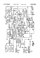
- FIG. 1 is an electrical block diagram of the automated ambient condition responsive daytime running light system of the present invention.
- FIG. 2 is a circuit diagram of the High Beam Modulator of FIG. 1.
- FIG. 3 is a circuit of the DRL high beam filament driver circuit of FIG. 1.
- FIG. 4 is a circuit diagram of the delay-OFF timer of FIG. 1.
- FIG. 5 is a circuit diagram of the navigational running light driver circuit of FIG. 1.
- FIG. 6 is a diagram of an alternate embodiment of navigational running light driver circuit which may be used in which the vehicle taillights will be illuminated whenever the vehicle ignition switch is on and the starter motor is off.
- the system is designed to be used with surface transportation vehicles having headlights, tail or parking lights, and other exterior lights such as ICC running lights, including automobiles, trucks, buses, and the like.
- the system includes a Daytime Running Light (DRL) control circuit for activating the highbeam filament HB of the headlights at a reduced power level whenever the vehicle Starter motor is deactivated following a Start cycle and with the Ignition in an "ON" condition.
- the DRL control circuit is automatically overridden in response to ambient light and weather condition sensors which activate a Navigational Lighting (NL) control circuit which is responsive to the sensors.
- NL Navigational Lighting
- navigational lights refer to the headlights, tail or parking brake lights and any other exterior lights associated with the vehicle such as ICC lights incorporated on trucks, trailers and buses.
- the Ignition 18 is the primary control input of the automated daytime running light system. With the Ignition input 18 in the Low or "OFF" state, a Starter Sequence Latch 24 is reset thereby providing a False signal to connected AND gate A4 and a High Beam Modulator 25. This False signal forces the AND gate's output to a False state, and turns OFF a High Beam Modulator 25 which supplies modulated power through the DRL control circuit to apply reduced power to the highbeam filaments HB of the vehicle headlights.
- a delay-OFF Timer 26 With AND gate's A4 output in a FALSE state when the Ignition input is in the Low or OFF state, power to a delay-OFF Timer 26 is also turned OFF. This action immediately removes any further enabling of the delay-OFF timer 26 which, if any of the vehicle navigational lights were previously ON, would function to maintain illumination of the navigational lights for a predetermined period after shutting OFF the Ignition.
- the length of time lights are retained ON after the Ignition is turned OFF may be varied by the manufacturer for any period thereby allowing an individual to turn OFF the Ignition while having the benefit of the operation of the navigational lights.
- the navigational lights of the vehicle are controlled in response to activation of one or more ambient condition sensors.
- FIG. 1 there is shown a light sensor amplifier circuit LS, fog or moisture sensor amplifier circuit FS, and a windshield wiper motor detector or sensor WWS.
- Each of the sensors or detectors are connected through an OR gate A5 to the AND gate A4.
- OR gate A5 to the AND gate A4.
- all inputs to the OR gate A5 are Low or False, therefore, the output of the AND gate A4 remains False so that no signal is supplied to the delay-OFF Timer 26 or to the navigational lights of the vehicle.
- the Starter Sequence Latch 24 includes two CMOS-4093 type Schmitt Trigger NAND gates A6 and A7 commonly available from Motorola, RCA, or National.
- the NAND gates are connected in a cross-coupled configuration and powered from a nominal eight to twelve volt source such as the vehicle battery. With this power supply voltage, the NAND gates respond to a logic LOW as less than five volts and a logic HIGH greater than eight volts.
- the highbeam filaments will be operating at approximately fifty percent (50%) of their normal operating voltage. Operating the highbeams at the reduced voltage prolongs the life of the highbeam filaments and also provides sufficient light intensity to make the headlights conspicuous, but without causing undue glare. Further, utilizing the highbeam filaments, it is possible to obtain a broader dissemination of the light than is possible with the lowbeams of the vehicle headlights.
- activation of the High Beam Modulator 25 requires that a parking brake indicator light input 35 be in an OFF condition, that is, the parking brake of the vehicle must be disengaged or released. If the parking brake indicator light input 35 is activated when the parking brake is applied, a TRUE or ON signal will be sent to an OR gate A2 thereby disabling the integrated DRL FET driver 36 which is connected at it's pin 8 to the output of the OR gate A2 through line 43 and thus terminating the power supply to the highbeam filaments through the MOSFET 37 of the DRL control circuit. In a like manner, when the starter is ON, a TRUE or ON signal is sent to OR gate A2 which is connected through line 43 to pin 8 of the DRL FET driver 36, again disabling the DRL FET driver 36.
- the High Beam Modulator 25 provides a switching frequency of approximately 100 Hertz with a duty cycle of approximately thirty percent (30%).
- the modulator 25 develops a resultant frequency which presents repetitive ON and OFF signals to the DRL integrated FET driver 36 which in turn powers the headlight filament HB resulting in an averaged reduced power.
- the High Beam Modulator 25 is preferably a multi-vibrator comprised of a CMOS-4093 Schmitt Trigger NAND gate available from Motorola, RCA, or National.
- the oscillator includes a feedback diode CR15 and a feedback resistor R26 which effectively adjust the duty cycle to provide for the appropriate power reduction.
- the oscillator base frequency is established with resistor R27 and capacitor CIO.
- the driver circuit includes an electronic MOSFET, Field Effect Transistor, output switching device 37 which controls the application of power to the highbeam filament HB.
- the MOSFET is utilized for maximum reliability and minimal heat dissipation within the electronic system. In order to completely turn ON an "N" channel MOSFET for minimum voltage drop across it, a voltage greater than 4 volts is required between its gate, 37', and source, 37", terminals which must be produced in addition to the nominal supply voltage.
- a Motorola MC33091 Integrated Driver Circuit also known as a high side driver or digital logic timer, 36, is utilized to generate the gate voltage for the MOSFET.
- Protected resistances R29 and R30 are provided between the integrated DRL FET driver 36 gate (pin 4) and source (pin 1) connections, respectively, to and with the respective gate and source connections of the MOSFET switch 37. These resistances protect the integrated DRL FET driver when transients occur on the external connections associated therewith.
- the source pin 1 of the integrated FET driver is also connected through resistor R30 to the highbeam filament HB. Control input to pin 7 of the integrated FET driver is from the output 38 from the AND gate A1 which receives the modulated signal from the High Beam Modulator 25.
- the digital logic timer circuits of the integrated DRL FET driver 36 are powered from a regulated and filtered power supply including C3, C4, C6, C7, C12, and VR2, and the positive twelve volt side of the vehicle battery as shown in FIG. 1, which supplies the voltage input at VCC or pin 5 of the DRL FET driver.
- the drain pin 2 of the DRL FET driver is also connected, together with the MOSFET drain, to the positive side of the vehicle battery through connection 39.
- the MOSFET gate 37' is further protected from transients through line 41, coupling diode CR20 and clamping Zener diode VR3 associated with the NL control circuit of FIG. 5.
- the MOSFET gate is also connected through capacitor C9 to ground.
- a further safety is incorporated into the system to avoid MOSFET failure in the event of lost ground connection.
- the cathode of diode CR19 is connected to the MOSFET source output 37' whereas the anode of CR19 is connected to ground.
- This diode provides an electrical reference to ground in the event the system ground connection is lost, not to maintain the operation of the system, but to prevent circuit failure. Without this diode component connection, a lost ground connection could ordinarily destroy MOSFET 37 because the integrated DRL FET driver 36 cannot develop full voltage potential to properly saturate the input gate to the MOSFET.
- the present invention also includes an external shut-off switch 40 which is connected at 42 to the AND gate A1. When switch 40 is closed, a ground connection is created which provides an OFF or FALSE signal to the input pin 7 of the integrated DRL FET driver 36.
- Pin 8 of the integrated DRL FET driver 36 is also connected to the output 43 of OR gate A2.
- the OR gate A2 receives signals from the Starter input 20 and the parking brake light indicator input 35. Therefore, whenever either of inputs 20 or 35 are High or ON, a shut-off signal is supplied by OR gate A2 thereby removing gate voltage from the DRL FET driver 36 and terminating power to the MOSFET 37. In this manner DRL operation of the High Beam filament will be terminated during activation of the starter or when the parking brake is engaged.
- Pin 8 of FET driver 36 is also connected to an integration filter circuit to ground through resistor R28 and capacitor C8.
- the DRL control circuit is also automatically overridden to shut-off power to the highbeam filament in response to the activation of the navigational light (NL) control circuit which is itself responsive to sensed ambient conditions.
- sensors associated with the system such as the light sensor LS, fog sensor FS, and the windshield wiper sensor WWS detect the presence of a condition which requires that power be supplied to the navigational lighting of the vehicle, the NL control circuit will automatically override the DRL control circuit. Further, upon removal of any condition requiring navigational lighting, the DRL circuit is again automatically activated to provide reduced power to the highbeam filament HB.
- the NL control circuit of the present invention includes the delay-OFF timer 26 which maintains the navigational lighting ON for a timed period after removal of a sensed condition.
- the delay-OFF timer 26 receives input signals from AND gate A4 through resistor R21 and diode CR9 and from the windshield wiper sensor WWS and Ignition 18 through the NAND gate A7 of the starter sequence latch 24 through diode CR1. If input is received through CR1 or CR9, a timing capacitor C2 will be charged and the output 46 of NAND gate A8 will be True or High.
- the resistor R3 and capacitor C2 govern the discharge rate.
- Zener diode VR1 reduces the True state voltage to a level compatible with an FET driver 48 of the NL control circuit so as to disable the driver circuit whenever the vehicle battery voltage is too low for proper FET driver operation.
- the timer is connected to ground through resistor R8.
- the NL control system also includes inputs to deactivate some or all of the navigational lights of the vehicle when the starter is engaged or when the parking brake of the vehicle has been applied. This feature is particularly useful for military and utility or service vehicles to extinguish power to the navigational lights when the motor is running.
- OR gate A5 when an ambient low light level, moist weather condition or activation of the windshield wipers is sensed by one of the sensors, a digital signal will be sent establishing a True condition at one of the inputs of OR gate A5.
- the output 45 signal from OR gate A5 is passed to AND gate A4 which powers the delay-OFF timer 26.
- the delay-OFF timer is connected at 46 to the input of AND gate A3 which is utilized to control power to a second integrated FET driver 48 which is associated with the NL control circuit.
- AND gate A3 is also connected at 42 to the external shut-OFF switch 40 so that when the switch is closed, the AND gate input will be connected to ground.
- the navigational integrated FET driver 48 receives a control input at pin 7 from the output of AND gate A3.
- the integrated driver 46 is preferably a Motorola MC33091 integrated High Side driver which generates gate voltage for a pair of MOSFET switches 50 and 52.
- MOSFET switch 50 is connected at 56 to power the input terminal HL of the conventional headlight dimmer switch, that is, the power is applied downstream of the conventional headlight switch and thus is applied to its output, whereas MOSFET switch 52 is connected at 57 to control power to an output PL to the parking lights and ICC lights.
- the gate pin 4 of the integrated FET driver 48 is connected through a protective resistor R24 to the gates 50' and 52' of the MOSFETS 50 and 52.
- resistors R20 and R19 located between source pin 1 of the integrated FET driver 48 and the source outputs 50" and 52" from the MOSFET switches 50 and 52, respectively. These resistances protect the integrated FET driver when transient currents occur on the external connections associated therewith.
- the digital logic timer circuits of the integrated FET driver 48 are also connected to the regulated and filter power supply including C3, C4, C6, C7, C12 and VR2 which supplies voltage input at VCC or pin 5 of the FET driver.
- the drain pin 2 of FET driver is also connected through resistor R23 and line 39 with the drains of MOSFETS 50 and 52 to the positive side of the vehicle battery.
- Each MOSFET gate is further transient protected through resistance R24, coupling diode CR16 and clamping Zener diode VR3.
- a further safety is incorporated in the NL control circuit to avoid MOSFET failure in the event of lost ground connection.
- the cathode of a diode CR17 is connected to the source output of MOSFET switch 50 whereas the annode of diode CR17 is connected to ground.
- the cathode of a diode CR18 is connected to the source output from the MOSFET switch 52 with its annode being connected to ground.
- Pin 8 of the FET driver 48 is also connected to an integration filter circuit R22 and C5 to ground.
- a signal representing a low light condition at the Light Sensor input LS is conditioned to provide a digital signal, and further, it may be seen that a TRUE condition at either input of OR gate A5 will be passed along to the delay-Off timer 26 which is connected to the navigational Integrated FET Driver 48.
- a TRUE signal is tapped from the headlight dimmer switch junction, HL, at 58 and is applied through OR gate A2 (R11, CR4, CR7) for the purpose of extinguishing the DRL FET driver 36 gate output voltage by applying a signal at pin 8 through connection 43.
- a Shut-OFF signal is applied to pin 8 of the Integrated FET Driver 48 through lines 54 and 55 to immediately extinguish all navigational lamps. This same signal is applied to pin 8 of the DRL FET driver 36 through line 54 and OR gate A2 to extinguish the DRL FET driver's gate output voltage. Also, it can be seen that a High signal applied to the Parking Brake indicator input 35 will disable FET Driver 48 through line 55 thereby disabling the navigational lighting function.
- the input signal to the delay-Off timer 26 will become FALSE thereby disabling the FET Driver 48 and extinguishing the navigation lights. Under these conditions a FALSE signal is applied to the input 58 of OR gate A2 which is connected to the source output pin 1 of FET driver 48 thus permitting the DRL FET driver 36 to become active and power the MOSFET switch 37 to illuminate the High Beam filament HB.
- the navigational light control output 56 is connected to the headlight dimmer switch input HL. Therefore, the connection is intermediate to the vehicle manual light switch and the vehicle dimmer switch. In this manner, whenever the manual switch is activated, voltage from the battery is applied along line 56 to the input 58 of OR gate A2 which shuts-OFF the DRL FET Driver 36.
- each of the navigational MOSFETS 50 and 52 are connected to receive their gate voltages from separate FET drivers 48 and 60.
- the NL control system utilizes separate FET drivers for controlling power to the headlamps and to the parking lights and running lights.
- the embodiment of invention shown in FIG. 6 also varies from the previous embodiment of FIG. 1 in that the parking lights are illuminated whenever the starter motor is OFF and the ignition is ON so that the vehicle taillights are illuminated at times the vehicle is operated with the exception of when the motor is being started. This provides an additional safety factor whenever the vehicle is operated.
- the output from latching switch 24 from the ignition 18 is supplied through connection 27 and line 61 to the input 7 of FET driver 60 whenever the daytime running light control circuit is activated to illuminate the high beam filaments.
- Both of the FET drivers 48 and 60 are controlled in the manner as previously discussed with respect to the embodiment incorporating a single FET driver for driving both MOSFETS 50 and 52. Therefore, whenever a condition is sensed which requires the activation of the NL control circuit, a TRUE signal will be applied to the delay-OFF timer 26 which will cause the output from AND gate A3 to be high thereby supplying input through connection 47 to the input pin 7 of the FET driver 48. In this embodiment, however, the output from the delay-OFF timer is applied directly through connection 61 to the input pin 7 of FET driver 60.
- the external shut-off switch 40 is only connected to prevent activation of NL FET driver 48 by providing a ground connection to the input of AND gate A3. Thus, in this embodiment, closing the external shut-off switch 40 will extinguish power to both the DRL High Beam HB filaments and the NL navigational headlights at HL while the parking light PL remain operated. See Truth Table IV, below.
- the gate pin 4 of FET driver 48 is connected through resistor R24 to the gate input of MOSFET 50.
- the drain pin 2 of FET driver 48 and the drain of MOSFET 50 are both connected through line 39 to the vehicle battery.
- the MOSFET gate is protected from transients through coupling diode CR16 and Zener diode VR3.
- Source pin 1 of FET driver 48 is connected through protective resistance R20 to the source output of the MOSFET 50 which output is connected through line 56 to power the input terminal HL of the conventional headlight dimmer switch in a manner as previously described with respect to the embodiment of FIG. 5.
- the source output of MOSFET switch 50 is connected through diode CR17 to ground.
- OR gate A2 receives an input signal responsive to MOSFET 50 being activated by way of connection 57 to connection 56 extending from MOSFET 50 to the input terminal HL of the headlight dimmer switch. In this manner, whenever the MOSFET 50 is activated to power the input terminal HL, OR gate A2 will supply a signal to pin 8 of the DRL FET driver 36 thereby extinguishing power from DRL FET 37 to the High Beam filaments HB.
- the FET driver 60 is connected to control the activation of MOSFET switch 52 which controls power to the parking and ICC running lights.
- Output gate pin 4 of FET driver 60 is connected through line 62 to the gate of the MOSFET 52.
- a protective resistance is provided by resistor R30. Both the FET driver and the MOSFET 50 are protected from transients by being connected at their gates through diode CR30 and Zener diode VR3 to line 39 extending to the battery and power supply.
- the source output pin 1 of FET driver 60 is connected through resistance R31 to the source output of MOSFET 52.
- the source output from MOSFET 52 is also connected to the parking light and ICC running light switches indicated at PL so that, when activated by the FET driver 60, power is supplied to the parking lights and ICC running lights. To avoid failure of MOSFET 52, the source output of the switch is connected through diode CR31 to ground.
- the drain pins 2 of both FET drivers 48 and 60 are connected through resistances R23 and R32, respectively, to the drains of their respective MOSFETS 50 and 52 and to the positive side of the vehicle battery through line 39.
- the digital logic timer circuits of the integrated FET drivers 48 and 60 are powered from the same regulated and filtered power supply disclosed in FIG. 5 which supplies voltage input at pins 5 of each FET driver.
- the NL control circuit of the present embodiment includes an input line 55 from the starter 18 and the parking brake indicator light 35. Whenever the starter is activated or the parking brake indicator light is ON or High, a signal is applied to pin 8 of each of the FET drivers 48 and 60 thereby extinguishing gate voltage to the MOSFETS 50 and 52. Pin 8 of each FET driver is also connected to a single integration filter circuit including resistor R22 and capacitor C5.
- the control of the DRL circuit is substantially identical to that previously described with respect to the embodiments of FIGS. 1-5.
- the parking lights will be illuminated at all times the ignition switch is ON and the starter switch is OFF and a redundancy feature has been provided by incorporating separate FET drivers for activation of the vehicle headlights and for activation of the vehicle parking and ICC running lights so that the parking and ICC running lights may remain ON when the external shut-off switch is OFF.
- a Truth Table, Table I, of the embodiment shown in FIG. 1 of the inputs (18, 20, LS, MS and WWS) and outputs (DRL HB, HL, PL) of the present invention when the parking brake indicator input is not in use is as follows:
- a Truth Table, Table II, of the embodiment shown in FIG. 6 of the inputs (18, 20, LS, MS and WWS) and outputs (DRL HB, HL, PL) of the present invention when the parking brake indicator input 35 is not in use is as follows:
- a Truth Table, Table III of both of the embodiments of the invention shown in FIGS. 1 and 6 of the inputs (18, 20, 35, LS, MS, WWS) and outputs (DRL HB, HL, PL) when the-parking brake indicator input is in use is as follows:
- a Truth Table, Table IV, of the embodiment of FIG. 6 of the inputs (18, 20, LS, MS and WWS) and outputs (DRL HB, HL, PL) of the present invention when the parking brake indicator input 35 is not in use and with the external shut-off (SO) closed to control the input to AND gate A3 to ground is as follows:
- the Automatic Light System of the present invention functions to provide low energy operation of the DRL high beam filament and normal operation of the parking lights during daylight hours when no adverse ambient conditions are sensed.
- the system automatically shuts-off the DRL operation and supplies power to the downstream side of the vehicle headlight switch and upstream of the vehicle dimmer switch. Therefore, if the conventional headlight switch is engaged, it will function to override and turn OFF the DRL circuit.
Abstract
Description
TABLE I __________________________________________________________________________ 5INPUTS 3 OUTPUTS __________________________________________________________________________ IGN(18) 1 1 1 1 1 1 1 1 1 1 1 1 1 1 1 1 ST (20) 1 0 0 0 0 0 0 0 0 1 1 1 1 1 1 1 LS 0 0 1 1 1 1 0 0 0 1 1 1 1 0 0 0 MS 0 0 0 1 1 0 1 1 0 0 1 1 0 1 1 0 WWS 0 0 0 0 1 1 1 0 1 0 0 1 1 1 0 1 DRL HB 0 1 0 0 0 0 0 0 0 0 0 0 0 0 0 0 HL 0 0 1 1 1 1 1 1 1 0 0 0 0 0 0 0 PL 0 0 1 1 1 1 1 1 1 0 0 0 0 0 0 0 __________________________________________________________________________
TABLE II __________________________________________________________________________ 5INPUTS 3 OUTPUTS __________________________________________________________________________ IGN(18) 1 1 1 1 1 1 1 1 1 1 1 1 1 1 1 1 ST (20) 1 0 0 0 0 0 0 0 0 1 1 1 1 1 1 1 LS 0 0 1 1 1 1 0 0 0 1 1 1 1 0 0 0 MS 0 0 0 1 1 0 1 1 0 0 1 1 0 1 1 0 WWS 0 0 0 0 1 1 1 0 1 0 0 1 1 1 0 1 DRL HB 0 1 0 0 0 0 0 0 0 0 0 0 0 0 0 0 HL 0 0 1 1 1 1 1 1 1 0 0 0 0 0 0 0 PL 0 1 1 1 1 1 1 1 1 0 0 0 0 0 0 0 __________________________________________________________________________
              TABLE III
______________________________________
         6 INPUTS       3 OUTPUTS
______________________________________
IGN (18) 1       1     1      1   1     1   1
ST (20)  0       0     0      0   0     0   0
LS       1       1     1      1   0     0   0
MS       0       1     1      0   1     1   0
WWS      0       0     1      1   1     0   1
DRL HB   0       0     0      0   0     0   0
HL       0       0     0      0   0     0   0
PL       0       0     0      0   0     0   0
PB       1       1     1      1   1     1   1
______________________________________
TABLE IV __________________________________________________________________________ 5INPUTS 3 OUTPUTS __________________________________________________________________________ IGN(18) 1 1 1 1 1 1 1 1 1 1 1 1 1 1 1 1 ST (20) 1 0 0 0 0 0 0 0 0 1 1 1 1 1 1 1 LS 0 0 1 1 1 1 0 0 0 1 1 1 1 0 0 0 MS 0 0 0 1 1 0 1 1 0 0 1 1 0 1 1 0 WWS 0 0 0 0 1 1 1 0 1 0 0 1 1 1 0 1 DRL HB 0 0 0 0 0 0 0 0 0 0 0 0 0 0 0 0 HL 0 0 0 0 0 0 0 0 0 0 0 0 0 0 0 0 PL 0 1 1 1 1 1 1 1 1 0 0 0 0 0 0 0 __________________________________________________________________________
Claims (38)
Priority Applications (1)
| Application Number | Priority Date | Filing Date | Title |
|---|---|---|---|
| US08/510,092 US5614788A (en) | 1995-01-31 | 1995-08-01 | Automated ambient condition responsive daytime running light system |
Applications Claiming Priority (2)
| Application Number | Priority Date | Filing Date | Title |
|---|---|---|---|
| US38164795A | 1995-01-31 | 1995-01-31 | |
| US08/510,092 US5614788A (en) | 1995-01-31 | 1995-08-01 | Automated ambient condition responsive daytime running light system |
Related Parent Applications (1)
| Application Number | Title | Priority Date | Filing Date |
|---|---|---|---|
| US38164795A Continuation-In-Part | 1995-01-31 | 1995-01-31 |
Publications (1)
| Publication Number | Publication Date |
|---|---|
| US5614788A true US5614788A (en) | 1997-03-25 |
Family
ID=23505837
Family Applications (1)
| Application Number | Title | Priority Date | Filing Date |
|---|---|---|---|
| US08/510,092 Expired - Lifetime US5614788A (en) | 1995-01-31 | 1995-08-01 | Automated ambient condition responsive daytime running light system |
Country Status (1)
| Country | Link |
|---|---|
| US (1) | US5614788A (en) |
Cited By (305)
| Publication number | Priority date | Publication date | Assignee | Title |
|---|---|---|---|---|
| US5736816A (en) * | 1996-06-24 | 1998-04-07 | Strenke; Leroy M. | Automatic on-off vehicle headlight system |
| US5742130A (en) * | 1991-11-12 | 1998-04-21 | Korkala; Heikki | Intelligent lamp or intelligent contact terminal for a lamp |
| US5886471A (en) * | 1996-03-18 | 1999-03-23 | Autosmart Light Switches, Inc. | Automatic vehicle light relay switching system for providing daytime running lights |
| US5912534A (en) * | 1996-03-18 | 1999-06-15 | Autosmart Light Switches, Inc. | Double relay light switching system for providing daytime running lights for vehicles |
| GB2337578A (en) * | 1998-05-18 | 1999-11-24 | Koito Mfg Co Ltd | A vehicle lamp system using environment detection means |
| WO2000017009A1 (en) * | 1998-09-18 | 2000-03-30 | Gentex Corporation | Continuously variable headlamp control |
| WO2000019389A1 (en) * | 1998-09-30 | 2000-04-06 | Clampco Sistemi Srl | System and device to signal obstacles to flight |
| WO2000049680A1 (en) * | 1999-02-16 | 2000-08-24 | Gentex Corporation | Rearview mirror with integrated microwave receiver |
| GB2347996A (en) * | 1999-02-22 | 2000-09-20 | Koito Mfg Co Ltd | Lighting device for vehicle comprising a plurality of lamps |
| EP1043193A1 (en) * | 1998-10-26 | 2000-10-11 | Kabushiki Kaisha Tokai-Rika-Denki-Seisakusho | Automatic control system for car accessory |
| US6175196B1 (en) * | 1999-07-02 | 2001-01-16 | Gary Dean Ragner | Photo-sensitive illuminated skate wheel |
| US6191531B1 (en) * | 1997-11-03 | 2001-02-20 | Valeo Auto-Electric Wischer Und Motoren Gmbh | Device for influencing a lighting installation as a function of ambient light |
| EP1089324A1 (en) | 1999-09-28 | 2001-04-04 | Philips Corporate Intellectual Property GmbH | Incandescent lamp |
| US6255639B1 (en) | 1997-04-02 | 2001-07-03 | Gentex Corporation | Control system to automatically dim vehicle head lamps |
| US6379013B1 (en) | 1999-01-25 | 2002-04-30 | Gentex Corporation | Vehicle equipment control with semiconductor light sensors |
| US6382378B1 (en) * | 1999-10-25 | 2002-05-07 | Alstom | Static system for supplying current through the ground for an electric vehicle and electric vehicle intended to be supplied by means of such a supply system |
| US6403942B1 (en) | 2000-03-20 | 2002-06-11 | Gentex Corporation | Automatic headlamp control system utilizing radar and an optical sensor |
| US20020070688A1 (en) * | 1997-08-26 | 2002-06-13 | Dowling Kevin J. | Light-emitting diode based products |
| US20020101197A1 (en) * | 1997-08-26 | 2002-08-01 | Lys Ihor A. | Packaged information systems |
| US20020171428A1 (en) * | 1997-11-03 | 2002-11-21 | Bertness Kevin I. | Electronic battery tester with network communication |
| US20020180445A1 (en) * | 2000-09-14 | 2002-12-05 | Bertness Kevin I. | Method and apparatus for testing cells and batteries embedded in series/parallel systems |
| US6507286B2 (en) * | 2000-12-29 | 2003-01-14 | Visteon Global Technologies, Inc. | Luminance control of automotive displays using an ambient light sensor |
| US20030011538A1 (en) * | 1997-08-26 | 2003-01-16 | Lys Ihor A. | Linear lighting apparatus and methods |
| US6515425B1 (en) * | 2000-06-28 | 2003-02-04 | International Truck Intellectual Property Company, L.L.C. | Headlight anti-glare system |
| US20030025481A1 (en) * | 1997-11-03 | 2003-02-06 | Bertness Kevin I. | Energy management system for automotive vehicle |
| US6522029B1 (en) * | 2000-10-30 | 2003-02-18 | International Truck Intellectual Property Company, L.L.C. | Remote keyless entry system for motor vehicles |
| US20030057890A1 (en) * | 1997-08-26 | 2003-03-27 | Lys Ihor A. | Systems and methods for controlling illumination sources |
| US20030090272A1 (en) * | 1997-11-03 | 2003-05-15 | Bertness Kevin I. | In-vehicle battery monitor |
| US20030107323A1 (en) * | 1998-09-18 | 2003-06-12 | Stam Joseph S. | Headlamp control to prevent glare |
| US6587573B1 (en) | 2000-03-20 | 2003-07-01 | Gentex Corporation | System for controlling exterior vehicle lights |
| US20030138131A1 (en) * | 1997-04-02 | 2003-07-24 | Stam Joseph S. | Vehicle lamp control |
| US20030137258A1 (en) * | 1997-08-26 | 2003-07-24 | Colin Piepgras | Light emitting diode based products |
| US20030155930A1 (en) * | 2000-04-25 | 2003-08-21 | Jes Thomsen | Current measuring circuit suited for batteries |
| EP1344683A2 (en) * | 2002-03-13 | 2003-09-17 | Adam Opel Ag | Daytime running light control unit for a vehicle and method to implement external lights as daytime running lights |
| US6631316B2 (en) | 2001-03-05 | 2003-10-07 | Gentex Corporation | Image processing system to control vehicle headlamps or other vehicle equipment |
| US6653615B2 (en) | 1998-06-09 | 2003-11-25 | Gentex Corporation | Imaging system for vehicle headlamp control |
| US20040008410A1 (en) * | 2002-07-09 | 2004-01-15 | Stam Joseph S. | Vehicle vision system with high dynamic range |
| US20040021853A1 (en) * | 2002-07-30 | 2004-02-05 | Stam Joseph S. | Light source detection and categorization system for automatic vehicle exterior light control and method of manufacturing |
| US20040036443A1 (en) * | 2000-03-27 | 2004-02-26 | Bertness Kevin I. | Modular battery tester for scan tool |
| US20040052076A1 (en) * | 1997-08-26 | 2004-03-18 | Mueller George G. | Controlled lighting methods and apparatus |
| US6717376B2 (en) | 1997-08-26 | 2004-04-06 | Color Kinetics, Incorporated | Automotive information systems |
| US20040113494A1 (en) * | 2000-09-01 | 2004-06-17 | Karuppana Samy V. | Daytime running light control using an intelligent power management system |
| US20040130909A1 (en) * | 2002-10-03 | 2004-07-08 | Color Kinetics Incorporated | Methods and apparatus for illuminating environments |
| US20040143380A1 (en) * | 2002-08-21 | 2004-07-22 | Stam Joseph S. | Image acquisition and processing methods for automatic vehicular exterior lighting control |
| US20040141321A1 (en) * | 2002-11-20 | 2004-07-22 | Color Kinetics, Incorporated | Lighting and other perceivable effects for toys and other consumer products |
| US20040145371A1 (en) * | 2001-10-17 | 2004-07-29 | Bertness Kevin I | Query based electronic battery tester |
| US6777891B2 (en) | 1997-08-26 | 2004-08-17 | Color Kinetics, Incorporated | Methods and apparatus for controlling devices in a networked lighting system |
| US20040160199A1 (en) * | 2001-05-30 | 2004-08-19 | Color Kinetics, Inc. | Controlled lighting methods and apparatus |
| US6788011B2 (en) | 1997-08-26 | 2004-09-07 | Color Kinetics, Incorporated | Multicolored LED lighting method and apparatus |
| US20040189309A1 (en) * | 2003-03-25 | 2004-09-30 | Bertness Kevin I. | Electronic battery tester cable |
| US20040201483A1 (en) * | 2003-02-21 | 2004-10-14 | Stam Joseph S. | Automatic vehicle exterior light control systems |
| US20040212321A1 (en) * | 2001-03-13 | 2004-10-28 | Lys Ihor A | Methods and apparatus for providing power to lighting devices |
| US20040212320A1 (en) * | 1997-08-26 | 2004-10-28 | Dowling Kevin J. | Systems and methods of generating control signals |
| US20040230358A1 (en) * | 2003-02-21 | 2004-11-18 | Stam Joseph S. | Monitoring and automatic equipment control systems |
| US20040232918A1 (en) * | 1996-07-29 | 2004-11-25 | Bertness Kevin I. | Automotive battery charging system tester |
| US20040251908A1 (en) * | 2003-06-16 | 2004-12-16 | Midtronics, Inc. | Electronic battery tester having a user interface to configure a printer |
| US20040257084A1 (en) * | 2003-06-23 | 2004-12-23 | Restaino Harvey A. | Cable for electronic battery tester |
| US20040263176A1 (en) * | 1996-07-29 | 2004-12-30 | Vonderhaar J. David | Electronic battery tester |
| US20050021475A1 (en) * | 1996-07-29 | 2005-01-27 | Bertness Kevin I. | Electronic battery tester with relative test output |
| US20050024061A1 (en) * | 1997-11-03 | 2005-02-03 | Michael Cox | Energy management system for automotive vehicle |
| US20050035752A1 (en) * | 1996-07-29 | 2005-02-17 | Bertness Kevin I. | Alternator tester |
| US20050040774A1 (en) * | 1999-11-18 | 2005-02-24 | Color Kinetics, Inc. | Methods and apparatus for generating and modulating white light illumination conditions |
| US20050052187A1 (en) * | 2003-09-05 | 2005-03-10 | Bertness Kevin I. | Method and apparatus for measuring a parameter of a vehicle electrical system |
| US20050057865A1 (en) * | 2003-07-25 | 2005-03-17 | Midtronics, Inc. | Shunt connection to a PCB of an energy management system employed in an automotive vehicle |
| US20050063194A1 (en) * | 1997-08-26 | 2005-03-24 | Color Kinetics, Incorporated | Vehicle lighting methods and apparatus |
| US20050083706A1 (en) * | 2003-10-21 | 2005-04-21 | Raymond Kesterson | Daytime running light module and system |
| US20050128751A1 (en) * | 2003-05-05 | 2005-06-16 | Color Kinetics, Incorporated | Lighting methods and systems |
| US20050162172A1 (en) * | 1997-11-03 | 2005-07-28 | Midtronics, Inc. | Wireless battery monitor |
| US20050184732A1 (en) * | 2004-02-20 | 2005-08-25 | Midtronics, Inc. | Replaceable clamp for electronic battery tester |
| US20050212521A1 (en) * | 2000-03-27 | 2005-09-29 | Midtronics, Inc. | Electronic battery tester or charger with databus connection |
| US20050218902A1 (en) * | 1999-04-08 | 2005-10-06 | Midtronics, Inc. | Battery test module |
| US20050225446A1 (en) * | 2004-04-13 | 2005-10-13 | Bertness Kevin I | Theft prevention device for automotive vehicle service centers |
| US20050231205A1 (en) * | 2000-03-27 | 2005-10-20 | Bertness Kevin I | Scan tool for electronic battery tester |
| US20050236998A1 (en) * | 1997-08-26 | 2005-10-27 | Color Kinetics, Inc. | Light emitting diode based products |
| US20050253533A1 (en) * | 2002-05-09 | 2005-11-17 | Color Kinetics Incorporated | Dimmable LED-based MR16 lighting apparatus methods |
| US20060006876A1 (en) * | 2004-07-12 | 2006-01-12 | Midtronics, Inc. | Wireless battery tester/charger |
| US20060017447A1 (en) * | 2004-07-22 | 2006-01-26 | Bertness Kevin I | Broad-band low-inductance cables for making kelvin connections to electrochemical cells and batteries |
| US20060038572A1 (en) * | 2004-08-20 | 2006-02-23 | Midtronics, Inc. | System for automatically gathering battery information for use during battery testing/charging |
| US20060106518A1 (en) * | 2004-11-18 | 2006-05-18 | Gentex Corporation | Image acquisition and processing systems for vehicle equipment control |
| US20060125483A1 (en) * | 2004-12-09 | 2006-06-15 | Midtronics, Inc. | Battery tester that calculates its own reference values |
| US20060192564A1 (en) * | 2005-02-16 | 2006-08-31 | Brown Dennis V | Centrally monitored sales of storage batteries |
| US20060217914A1 (en) * | 2000-03-27 | 2006-09-28 | Bertness Kevin I | Battery testers with secondary functionality |
| US20060267575A1 (en) * | 2004-04-13 | 2006-11-30 | Midtronics, Inc. | Theft prevention device for automotive vehicle service centers |
| US20060279288A1 (en) * | 2003-11-11 | 2006-12-14 | Midtronics, Inc. | Apparatus and method for simulating a battery tester with a fixed resistance load |
| US20070090844A1 (en) * | 2002-12-31 | 2007-04-26 | Midtronics, Inc. | Battery monitoring system |
| DE102005055476A1 (en) * | 2005-11-22 | 2007-05-24 | Robert Bosch Gmbh | Device for controlling light sources of a motor vehicle and method for controlling a rest lighting system of a motor vehicle |
| US20070159177A1 (en) * | 1997-11-03 | 2007-07-12 | Midtronics, Inc. | Automotive vehicle electrical system diagnostic device |
| US20070244660A1 (en) * | 1996-07-29 | 2007-10-18 | Bertness Kevin I | Alternator tester |
| US20080007180A1 (en) * | 2003-10-21 | 2008-01-10 | Raymond Kesterson | Directional lamp daytime running light module and vehicular turn signal control system |
| US20080054161A1 (en) * | 1993-02-26 | 2008-03-06 | Donnelly Corporation | Image sensing system for a vehicle |
| US20080130267A1 (en) * | 2000-09-27 | 2008-06-05 | Philips Solid-State Lighting Solutions | Methods and systems for illuminating household products |
| US20080204030A1 (en) * | 2007-02-27 | 2008-08-28 | Midtronics, Inc. | Battery tester with promotion feature |
| US20090010494A1 (en) * | 1997-04-02 | 2009-01-08 | Gentex Corporation | System for controlling vehicle equipment |
| US20090045323A1 (en) * | 2007-08-17 | 2009-02-19 | Yuesheng Lu | Automatic Headlamp Control System |
| US20090160451A1 (en) * | 2000-03-27 | 2009-06-25 | Midtronics, Inc. | Scan tool for electronic battery tester |
| US20090192704A1 (en) * | 2006-03-08 | 2009-07-30 | Tomtom International B.V. | Portable navigation device |
| US20090208058A1 (en) * | 2004-04-15 | 2009-08-20 | Donnelly Corporation | Imaging system for vehicle |
| US20090311919A1 (en) * | 2008-06-16 | 2009-12-17 | Midtronics, Inc. | Clamp for Electrically Coupling to a Battery Contact |
| US7653215B2 (en) | 1997-04-02 | 2010-01-26 | Gentex Corporation | System for controlling exterior vehicle lights |
| US20100020170A1 (en) * | 2008-07-24 | 2010-01-28 | Higgins-Luthman Michael J | Vehicle Imaging System |
| US7655894B2 (en) | 1996-03-25 | 2010-02-02 | Donnelly Corporation | Vehicular image sensing system |
| US7705602B2 (en) | 1997-11-03 | 2010-04-27 | Midtronics, Inc. | Automotive vehicle electrical system diagnostic device |
| US20100114509A1 (en) * | 2007-02-08 | 2010-05-06 | Techimp Technologies S.A. | Method for processing data pertaining to an activity of partial electrical discharges |
| US20100214791A1 (en) * | 2006-08-11 | 2010-08-26 | Donnelly Corporation | Automatic headlamp control system |
| US7808375B2 (en) | 2007-04-16 | 2010-10-05 | Midtronics, Inc. | Battery run down indicator |
| US20100265048A1 (en) * | 2007-09-11 | 2010-10-21 | Yuesheng Lu | Imaging System for Vehicle |
| US20110018441A1 (en) * | 2007-07-26 | 2011-01-27 | Panasonic Electric Works Co., Ltd. | Vehicle-mounted load controller, vehicle-mounted headlight device, and vehicle-mounted taillight device |
| US7926975B2 (en) | 2007-12-21 | 2011-04-19 | Altair Engineering, Inc. | Light distribution using a light emitting diode assembly |
| US7938562B2 (en) | 2008-10-24 | 2011-05-10 | Altair Engineering, Inc. | Lighting including integral communication apparatus |
| US7946729B2 (en) | 2008-07-31 | 2011-05-24 | Altair Engineering, Inc. | Fluorescent tube replacement having longitudinally oriented LEDs |
| US20110122249A1 (en) * | 2004-09-30 | 2011-05-26 | Donnelly Corporation | Vision system for vehicle |
| US7976196B2 (en) | 2008-07-09 | 2011-07-12 | Altair Engineering, Inc. | Method of forming LED-based light and resulting LED-based light |
| US7977914B2 (en) | 2003-10-08 | 2011-07-12 | Midtronics, Inc. | Battery maintenance tool with probe light |
| US20110193961A1 (en) * | 2010-02-10 | 2011-08-11 | Magna Mirrors Of America, Inc. | Imaging and display system for vehicle |
| US8070332B2 (en) | 2007-07-12 | 2011-12-06 | Magna Electronics Inc. | Automatic lighting system with adaptive function |
| US20120038474A1 (en) * | 2010-08-12 | 2012-02-16 | David Joseph De Sanzo | Vehicle lighting control apparatus and method |
| US8118447B2 (en) | 2007-12-20 | 2012-02-21 | Altair Engineering, Inc. | LED lighting apparatus with swivel connection |
| US8164343B2 (en) | 2003-09-05 | 2012-04-24 | Midtronics, Inc. | Method and apparatus for measuring a parameter of a vehicle electrical system |
| US8203440B2 (en) | 1993-02-26 | 2012-06-19 | Donnelly Corporation | Vehicular vision system |
| US8203345B2 (en) | 2007-12-06 | 2012-06-19 | Midtronics, Inc. | Storage battery and battery tester |
| US8214084B2 (en) | 2008-10-24 | 2012-07-03 | Ilumisys, Inc. | Integration of LED lighting with building controls |
| US8217830B2 (en) | 2007-01-25 | 2012-07-10 | Magna Electronics Inc. | Forward facing sensing system for a vehicle |
| US8256924B2 (en) | 2008-09-15 | 2012-09-04 | Ilumisys, Inc. | LED-based light having rapidly oscillating LEDs |
| US8299695B2 (en) | 2009-06-02 | 2012-10-30 | Ilumisys, Inc. | Screw-in LED bulb comprising a base having outwardly projecting nodes |
| US8306690B2 (en) | 2007-07-17 | 2012-11-06 | Midtronics, Inc. | Battery tester for electric vehicle |
| US8324817B2 (en) | 2008-10-24 | 2012-12-04 | Ilumisys, Inc. | Light and light sensor |
| US8330381B2 (en) | 2009-05-14 | 2012-12-11 | Ilumisys, Inc. | Electronic circuit for DC conversion of fluorescent lighting ballast |
| US8344685B2 (en) | 2004-08-20 | 2013-01-01 | Midtronics, Inc. | System for automatically gathering battery information |
| US8360599B2 (en) | 2008-05-23 | 2013-01-29 | Ilumisys, Inc. | Electric shock resistant L.E.D. based light |
| US8362885B2 (en) | 2000-03-31 | 2013-01-29 | Donnelly Corporation | Vehicular rearview mirror system |
| US8362710B2 (en) | 2009-01-21 | 2013-01-29 | Ilumisys, Inc. | Direct AC-to-DC converter for passive component minimization and universal operation of LED arrays |
| US8376595B2 (en) | 2009-05-15 | 2013-02-19 | Magna Electronics, Inc. | Automatic headlamp control |
| US8421366B2 (en) | 2009-06-23 | 2013-04-16 | Ilumisys, Inc. | Illumination device including LEDs and a switching power control system |
| US8436619B2 (en) | 2004-08-20 | 2013-05-07 | Midtronics, Inc. | Integrated tag reader and environment sensor |
| US8442877B2 (en) | 2004-08-20 | 2013-05-14 | Midtronics, Inc. | Simplification of inventory management |
| US8444292B2 (en) | 2008-10-24 | 2013-05-21 | Ilumisys, Inc. | End cap substitute for LED-based tube replacement light |
| US8446470B2 (en) | 2007-10-04 | 2013-05-21 | Magna Electronics, Inc. | Combined RGB and IR imaging sensor |
| US8454193B2 (en) | 2010-07-08 | 2013-06-04 | Ilumisys, Inc. | Independent modules for LED fluorescent light tube replacement |
| US8513949B2 (en) | 2000-03-27 | 2013-08-20 | Midtronics, Inc. | Electronic battery tester or charger with databus connection |
| US8523394B2 (en) | 2010-10-29 | 2013-09-03 | Ilumisys, Inc. | Mechanisms for reducing risk of shock during installation of light tube |
| US8541958B2 (en) | 2010-03-26 | 2013-09-24 | Ilumisys, Inc. | LED light with thermoelectric generator |
| US8540401B2 (en) | 2010-03-26 | 2013-09-24 | Ilumisys, Inc. | LED bulb with internal heat dissipating structures |
| US8556452B2 (en) | 2009-01-15 | 2013-10-15 | Ilumisys, Inc. | LED lens |
| US8596813B2 (en) | 2010-07-12 | 2013-12-03 | Ilumisys, Inc. | Circuit board mount for LED light tube |
| US8620523B2 (en) | 2011-06-24 | 2013-12-31 | Gentex Corporation | Rearview assembly with multiple ambient light sensors |
| US8629768B2 (en) | 1999-08-12 | 2014-01-14 | Donnelly Corporation | Vehicle vision system |
| US8643724B2 (en) | 1996-05-22 | 2014-02-04 | Magna Electronics Inc. | Multi-camera vision system for a vehicle |
| US8653984B2 (en) | 2008-10-24 | 2014-02-18 | Ilumisys, Inc. | Integration of LED lighting control with emergency notification systems |
| US8665079B2 (en) | 2002-05-03 | 2014-03-04 | Magna Electronics Inc. | Vision system for vehicle |
| US8664880B2 (en) | 2009-01-21 | 2014-03-04 | Ilumisys, Inc. | Ballast/line detection circuit for fluorescent replacement lamps |
| US8674626B2 (en) | 2008-09-02 | 2014-03-18 | Ilumisys, Inc. | LED lamp failure alerting system |
| US8694224B2 (en) | 2012-03-01 | 2014-04-08 | Magna Electronics Inc. | Vehicle yaw rate correction |
| EP2722226A1 (en) * | 2012-10-18 | 2014-04-23 | Koito Manufacturing Co., Ltd. | Lighting control system for vehicle lamp |
| US8738309B2 (en) | 2010-09-30 | 2014-05-27 | Midtronics, Inc. | Battery pack maintenance for electric vehicles |
| US8866396B2 (en) | 2000-02-11 | 2014-10-21 | Ilumisys, Inc. | Light tube and power supply circuit |
| US8872517B2 (en) | 1996-07-29 | 2014-10-28 | Midtronics, Inc. | Electronic battery tester with battery age input |
| US8870415B2 (en) | 2010-12-09 | 2014-10-28 | Ilumisys, Inc. | LED fluorescent tube replacement light with reduced shock hazard |
| US8874317B2 (en) | 2009-07-27 | 2014-10-28 | Magna Electronics Inc. | Parking assist system |
| US8879139B2 (en) | 2012-04-24 | 2014-11-04 | Gentex Corporation | Display mirror assembly |
| US8886401B2 (en) | 2003-10-14 | 2014-11-11 | Donnelly Corporation | Driver assistance system for a vehicle |
| US8901823B2 (en) | 2008-10-24 | 2014-12-02 | Ilumisys, Inc. | Light and light sensor |
| US8912476B2 (en) | 2003-02-21 | 2014-12-16 | Gentex Corporation | Automatic vehicle exterior light control system assemblies |
| US8924078B2 (en) | 2004-11-18 | 2014-12-30 | Gentex Corporation | Image acquisition and processing system for vehicle equipment control |
| US8958998B2 (en) | 1997-11-03 | 2015-02-17 | Midtronics, Inc. | Electronic battery tester with network communication |
| US8964024B2 (en) | 2012-08-02 | 2015-02-24 | Gentex Corporation | System and method for controlling exterior vehicle lights responsive to detection of a semi-truck |
| US8977439B2 (en) | 2012-06-12 | 2015-03-10 | Genetex Corporation | Vehicle imaging system providing multi-stage aiming stability indication |
| US8983135B2 (en) | 2012-06-01 | 2015-03-17 | Gentex Corporation | System and method for controlling vehicle equipment responsive to a multi-stage village detection |
| US9014904B2 (en) | 2004-12-23 | 2015-04-21 | Magna Electronics Inc. | Driver assistance system for vehicle |
| US9018958B2 (en) | 2003-09-05 | 2015-04-28 | Midtronics, Inc. | Method and apparatus for measuring a parameter of a vehicle electrical system |
| US9041806B2 (en) | 2009-09-01 | 2015-05-26 | Magna Electronics Inc. | Imaging and display system for vehicle |
| US9057493B2 (en) | 2010-03-26 | 2015-06-16 | Ilumisys, Inc. | LED light tube with dual sided light distribution |
| US9072171B2 (en) | 2011-08-24 | 2015-06-30 | Ilumisys, Inc. | Circuit board mount for LED light |
| US9085261B2 (en) | 2011-01-26 | 2015-07-21 | Magna Electronics Inc. | Rear vision system with trailer angle detection |
| US9092986B2 (en) | 2013-02-04 | 2015-07-28 | Magna Electronics Inc. | Vehicular vision system |
| US9090234B2 (en) | 2012-11-19 | 2015-07-28 | Magna Electronics Inc. | Braking control system for vehicle |
| US9117123B2 (en) | 2010-07-05 | 2015-08-25 | Magna Electronics Inc. | Vehicular rear view camera display system with lifecheck function |
| US9126525B2 (en) | 2009-02-27 | 2015-09-08 | Magna Electronics Inc. | Alert system for vehicle |
| US9146898B2 (en) | 2011-10-27 | 2015-09-29 | Magna Electronics Inc. | Driver assist system with algorithm switching |
| US9163794B2 (en) | 2012-07-06 | 2015-10-20 | Ilumisys, Inc. | Power supply assembly for LED-based light tube |
| US9180908B2 (en) | 2010-11-19 | 2015-11-10 | Magna Electronics Inc. | Lane keeping system and lane centering system |
| US9184518B2 (en) | 2012-03-02 | 2015-11-10 | Ilumisys, Inc. | Electrical connector header for an LED-based light |
| US9191574B2 (en) | 2001-07-31 | 2015-11-17 | Magna Electronics Inc. | Vehicular vision system |
| US9187029B2 (en) | 2013-10-01 | 2015-11-17 | Gentex Corporation | System and method for controlling exterior vehicle lights on motorways |
| US9194943B2 (en) | 2011-04-12 | 2015-11-24 | Magna Electronics Inc. | Step filter for estimating distance in a time-of-flight ranging system |
| US9201120B2 (en) | 2010-08-12 | 2015-12-01 | Midtronics, Inc. | Electronic battery tester for testing storage battery |
| US9207116B2 (en) | 2013-02-12 | 2015-12-08 | Gentex Corporation | Light sensor |
| US20150360665A1 (en) * | 2014-06-13 | 2015-12-17 | Ford Global Technolgies, Llc | Method for operating an electromechanical vehicle braking |
| US9224889B2 (en) | 2011-08-05 | 2015-12-29 | Gentex Corporation | Optical assembly for a light sensor, light sensor assembly using the optical assembly, and vehicle rearview assembly using the light sensor assembly |
| US9229062B2 (en) | 2010-05-27 | 2016-01-05 | Midtronics, Inc. | Electronic storage battery diagnostic system |
| US9245448B2 (en) | 2001-07-31 | 2016-01-26 | Magna Electronics Inc. | Driver assistance system for a vehicle |
| US9244100B2 (en) | 2013-03-15 | 2016-01-26 | Midtronics, Inc. | Current clamp with jaw closure detection |
| US9255955B2 (en) | 2003-09-05 | 2016-02-09 | Midtronics, Inc. | Method and apparatus for measuring a parameter of a vehicle electrical system |
| US9260095B2 (en) | 2013-06-19 | 2016-02-16 | Magna Electronics Inc. | Vehicle vision system with collision mitigation |
| US9264672B2 (en) | 2010-12-22 | 2016-02-16 | Magna Mirrors Of America, Inc. | Vision display system for vehicle |
| US9267650B2 (en) | 2013-10-09 | 2016-02-23 | Ilumisys, Inc. | Lens for an LED-based light |
| US9271367B2 (en) | 2012-07-09 | 2016-02-23 | Ilumisys, Inc. | System and method for controlling operation of an LED-based light |
| US9274157B2 (en) | 2007-07-17 | 2016-03-01 | Midtronics, Inc. | Battery tester for electric vehicle |
| US9285084B2 (en) | 2013-03-14 | 2016-03-15 | Ilumisys, Inc. | Diffusers for LED-based lights |
| US9312575B2 (en) | 2013-05-16 | 2016-04-12 | Midtronics, Inc. | Battery testing system and method |
| US9317758B2 (en) | 2013-08-19 | 2016-04-19 | Gentex Corporation | Vehicle imaging system and method for distinguishing reflective objects from lights of another vehicle |
| US9327693B2 (en) | 2013-04-10 | 2016-05-03 | Magna Electronics Inc. | Rear collision avoidance system for vehicle |
| US9340227B2 (en) | 2012-08-14 | 2016-05-17 | Magna Electronics Inc. | Vehicle lane keep assist system |
| US9419311B2 (en) | 2010-06-18 | 2016-08-16 | Midtronics, Inc. | Battery maintenance device with thermal buffer |
| US9425487B2 (en) | 2010-03-03 | 2016-08-23 | Midtronics, Inc. | Monitor for front terminal batteries |
| US9434327B2 (en) | 2013-11-15 | 2016-09-06 | Gentex Corporation | Imaging system including dynamic compensation for color attenuation for vehicle windscreens |
| US9446713B2 (en) | 2012-09-26 | 2016-09-20 | Magna Electronics Inc. | Trailer angle detection system |
| US9481301B2 (en) | 2012-12-05 | 2016-11-01 | Magna Electronics Inc. | Vehicle vision system utilizing camera synchronization |
| US9487235B2 (en) | 2014-04-10 | 2016-11-08 | Magna Electronics Inc. | Vehicle control system with adaptive wheel angle correction |
| US9496720B2 (en) | 2004-08-20 | 2016-11-15 | Midtronics, Inc. | System for automatically gathering battery information |
| US9495876B2 (en) | 2009-07-27 | 2016-11-15 | Magna Electronics Inc. | Vehicular camera with on-board microcontroller |
| US9499139B2 (en) | 2013-12-05 | 2016-11-22 | Magna Electronics Inc. | Vehicle monitoring system |
| US9508014B2 (en) | 2013-05-06 | 2016-11-29 | Magna Electronics Inc. | Vehicular multi-camera vision system |
| US9510400B2 (en) | 2014-05-13 | 2016-11-29 | Ilumisys, Inc. | User input systems for an LED-based light |
| US9511715B2 (en) | 2014-01-31 | 2016-12-06 | Gentex Corporation | Backlighting assembly for display for reducing cross-hatching |
| US9547795B2 (en) | 2011-04-25 | 2017-01-17 | Magna Electronics Inc. | Image processing method for detecting objects using relative motion |
| US9558409B2 (en) | 2012-09-26 | 2017-01-31 | Magna Electronics Inc. | Vehicle vision system with trailer angle detection |
| US9574717B2 (en) | 2014-01-22 | 2017-02-21 | Ilumisys, Inc. | LED-based light with addressed LEDs |
| US9575315B2 (en) | 2013-09-24 | 2017-02-21 | Gentex Corporation | Display mirror assembly |
| US9588185B2 (en) | 2010-02-25 | 2017-03-07 | Keith S. Champlin | Method and apparatus for detecting cell deterioration in an electrochemical cell or battery |
| US9592812B2 (en) | 2014-06-13 | 2017-03-14 | Ford Global Technologies, Llc | Method for operating an electromechanical vehicle brake system |
| US9619720B2 (en) | 2013-08-19 | 2017-04-11 | Gentex Corporation | Vehicle imaging system and method for distinguishing between vehicle tail lights and flashing red stop lights |
| USD783480S1 (en) | 2014-12-05 | 2017-04-11 | Gentex Corporation | Rearview device |
| US9623878B2 (en) | 2014-04-02 | 2017-04-18 | Magna Electronics Inc. | Personalized driver assistance system for vehicle |
| US20170142800A1 (en) * | 2015-11-13 | 2017-05-18 | Custom Lights Ug | Lamp kit for installation in a motor vehicle, and a motor vehicle |
| US9681062B2 (en) | 2011-09-26 | 2017-06-13 | Magna Electronics Inc. | Vehicle camera image quality improvement in poor visibility conditions by contrast amplification |
| US9694752B2 (en) | 2014-11-07 | 2017-07-04 | Gentex Corporation | Full display mirror actuator |
| US9694751B2 (en) | 2014-09-19 | 2017-07-04 | Gentex Corporation | Rearview assembly |
| US9720278B2 (en) | 2015-01-22 | 2017-08-01 | Gentex Corporation | Low cost optical film stack |
| US9743002B2 (en) | 2012-11-19 | 2017-08-22 | Magna Electronics Inc. | Vehicle vision system with enhanced display functions |
| US9744907B2 (en) | 2014-12-29 | 2017-08-29 | Gentex Corporation | Vehicle vision system having adjustable displayed field of view |
| US9751465B2 (en) | 2012-04-16 | 2017-09-05 | Magna Electronics Inc. | Vehicle vision system with reduced image color data processing by use of dithering |
| US9761142B2 (en) | 2012-09-04 | 2017-09-12 | Magna Electronics Inc. | Driver assistant system using influence mapping for conflict avoidance path determination |
| USD797627S1 (en) | 2015-10-30 | 2017-09-19 | Gentex Corporation | Rearview mirror device |
| USD798207S1 (en) | 2015-10-30 | 2017-09-26 | Gentex Corporation | Rearview mirror assembly |
| USD800618S1 (en) | 2015-11-02 | 2017-10-24 | Gentex Corporation | Toggle paddle for a rear view device |
| US9834146B2 (en) | 2014-04-01 | 2017-12-05 | Gentex Corporation | Automatic display mirror assembly |
| US9851411B2 (en) | 2012-06-28 | 2017-12-26 | Keith S. Champlin | Suppressing HF cable oscillations during dynamic measurements of cells and batteries |
| US9870753B2 (en) | 2013-02-12 | 2018-01-16 | Gentex Corporation | Light sensor having partially opaque optic |
| USD809984S1 (en) | 2016-12-07 | 2018-02-13 | Gentex Corporation | Rearview assembly |
| US9900522B2 (en) | 2010-12-01 | 2018-02-20 | Magna Electronics Inc. | System and method of establishing a multi-camera image using pixel remapping |
| US9900490B2 (en) | 2011-09-21 | 2018-02-20 | Magna Electronics Inc. | Vehicle vision system using image data transmission and power supply via a coaxial cable |
| US9923289B2 (en) | 2014-01-16 | 2018-03-20 | Midtronics, Inc. | Battery clamp with endoskeleton design |
| US9925980B2 (en) | 2014-09-17 | 2018-03-27 | Magna Electronics Inc. | Vehicle collision avoidance system with enhanced pedestrian avoidance |
| USD817238S1 (en) | 2016-04-29 | 2018-05-08 | Gentex Corporation | Rearview device |
| US9966676B2 (en) | 2015-09-28 | 2018-05-08 | Midtronics, Inc. | Kelvin connector adapter for storage battery |
| US9988047B2 (en) | 2013-12-12 | 2018-06-05 | Magna Electronics Inc. | Vehicle control system with traffic driving control |
| US9995854B2 (en) | 2015-04-20 | 2018-06-12 | Gentex Corporation | Rearview assembly with applique |
| US9994156B2 (en) | 2015-10-30 | 2018-06-12 | Gentex Corporation | Rearview device |
| US10025138B2 (en) | 2016-06-06 | 2018-07-17 | Gentex Corporation | Illuminating display with light gathering structure |
| US10027930B2 (en) | 2013-03-29 | 2018-07-17 | Magna Electronics Inc. | Spectral filtering for vehicular driver assistance systems |
| US10025994B2 (en) | 2012-12-04 | 2018-07-17 | Magna Electronics Inc. | Vehicle vision system utilizing corner detection |
| US10046649B2 (en) | 2012-06-28 | 2018-08-14 | Midtronics, Inc. | Hybrid and electric vehicle battery pack maintenance device |
| US10055651B2 (en) | 2016-03-08 | 2018-08-21 | Magna Electronics Inc. | Vehicle vision system with enhanced lane tracking |
| US10071689B2 (en) | 2014-11-13 | 2018-09-11 | Gentex Corporation | Rearview mirror system with a display |
| US10078789B2 (en) | 2015-07-17 | 2018-09-18 | Magna Electronics Inc. | Vehicle parking assist system with vision-based parking space detection |
| US10086870B2 (en) | 2015-08-18 | 2018-10-02 | Magna Electronics Inc. | Trailer parking assist system for vehicle |
| US10089537B2 (en) | 2012-05-18 | 2018-10-02 | Magna Electronics Inc. | Vehicle vision system with front and rear camera integration |
| US10112540B2 (en) | 2015-05-18 | 2018-10-30 | Gentex Corporation | Full display rearview device |
| US10132971B2 (en) | 2016-03-04 | 2018-11-20 | Magna Electronics Inc. | Vehicle camera with multiple spectral filters |
| US10131279B2 (en) | 2014-12-03 | 2018-11-20 | Gentex Corporation | Display mirror assembly with an RF shield bezel |
| US10144419B2 (en) | 2015-11-23 | 2018-12-04 | Magna Electronics Inc. | Vehicle dynamic control system for emergency handling |
| US10161568B2 (en) | 2015-06-01 | 2018-12-25 | Ilumisys, Inc. | LED-based light with canted outer walls |
| US10160382B2 (en) | 2014-02-04 | 2018-12-25 | Magna Electronics Inc. | Trailer backup assist system |
| US10222224B2 (en) | 2013-06-24 | 2019-03-05 | Magna Electronics Inc. | System for locating a parking space based on a previously parked space |
| US10222397B2 (en) | 2014-09-26 | 2019-03-05 | Midtronics, Inc. | Cable connector for electronic battery tester |
| US10232797B2 (en) | 2013-04-29 | 2019-03-19 | Magna Electronics Inc. | Rear vision system for vehicle with dual purpose signal lines |
| USD845851S1 (en) | 2016-03-31 | 2019-04-16 | Gentex Corporation | Rearview device |
| CN109695852A (en) * | 2017-10-24 | 2019-04-30 | 株式会社小糸制作所 | The control device and lamp system for vehicle of lamps apparatus for vehicle |
| US10317468B2 (en) | 2015-01-26 | 2019-06-11 | Midtronics, Inc. | Alternator tester |
| US10326969B2 (en) | 2013-08-12 | 2019-06-18 | Magna Electronics Inc. | Vehicle vision system with reduction of temporal noise in images |
| USD854473S1 (en) | 2016-12-16 | 2019-07-23 | Gentex Corporation | Rearview assembly |
| US10429449B2 (en) | 2011-11-10 | 2019-10-01 | Midtronics, Inc. | Battery pack tester |
| US10457209B2 (en) | 2012-02-22 | 2019-10-29 | Magna Electronics Inc. | Vehicle vision system with multi-paned view |
| US10457358B1 (en) | 2018-05-08 | 2019-10-29 | Peter Granata Design, LLC | Marine safety lighting |
| US10473555B2 (en) | 2014-07-14 | 2019-11-12 | Midtronics, Inc. | Automotive maintenance system |
| US10493916B2 (en) | 2012-02-22 | 2019-12-03 | Magna Electronics Inc. | Vehicle camera system with image manipulation |
| US10523904B2 (en) | 2013-02-04 | 2019-12-31 | Magna Electronics Inc. | Vehicle data recording system |
| US10567705B2 (en) | 2013-06-10 | 2020-02-18 | Magna Electronics Inc. | Coaxial cable with bidirectional data transmission |
| US10608353B2 (en) | 2016-06-28 | 2020-03-31 | Midtronics, Inc. | Battery clamp |
| US10609335B2 (en) | 2012-03-23 | 2020-03-31 | Magna Electronics Inc. | Vehicle vision system with accelerated object confirmation |
| US10640040B2 (en) | 2011-11-28 | 2020-05-05 | Magna Electronics Inc. | Vision system for vehicle |
| US10685623B2 (en) | 2015-10-30 | 2020-06-16 | Gentex Corporation | Toggle paddle |
| US10705332B2 (en) | 2014-03-21 | 2020-07-07 | Gentex Corporation | Tri-modal display mirror assembly |
| US10735638B2 (en) | 2017-03-17 | 2020-08-04 | Gentex Corporation | Dual display reverse camera system |
| US10793067B2 (en) | 2011-07-26 | 2020-10-06 | Magna Electronics Inc. | Imaging system for vehicle |
| US10819943B2 (en) | 2015-05-07 | 2020-10-27 | Magna Electronics Inc. | Vehicle vision system with incident recording function |
| US10843574B2 (en) | 2013-12-12 | 2020-11-24 | Midtronics, Inc. | Calibration and programming of in-vehicle battery sensors |
| WO2020244079A1 (en) * | 2019-06-05 | 2020-12-10 | 华域视觉科技(上海)有限公司 | Vehicle headlamp and vehicle |
| US10875403B2 (en) | 2015-10-27 | 2020-12-29 | Magna Electronics Inc. | Vehicle vision system with enhanced night vision |
| US11054480B2 (en) | 2016-10-25 | 2021-07-06 | Midtronics, Inc. | Electrical load for electronic battery tester and electronic battery tester including such electrical load |
| US11178353B2 (en) | 2015-06-22 | 2021-11-16 | Gentex Corporation | System and method for processing streamed video images to correct for flicker of amplitude-modulated lights |
| US11277558B2 (en) | 2016-02-01 | 2022-03-15 | Magna Electronics Inc. | Vehicle vision system with master-slave camera configuration |
| US11325479B2 (en) | 2012-06-28 | 2022-05-10 | Midtronics, Inc. | Hybrid and electric vehicle battery maintenance device |
| US11433809B2 (en) | 2016-02-02 | 2022-09-06 | Magna Electronics Inc. | Vehicle vision system with smart camera video output |
| US11474153B2 (en) | 2019-11-12 | 2022-10-18 | Midtronics, Inc. | Battery pack maintenance system |
| US11486930B2 (en) | 2020-01-23 | 2022-11-01 | Midtronics, Inc. | Electronic battery tester with battery clamp storage holsters |
| US11513160B2 (en) | 2018-11-29 | 2022-11-29 | Midtronics, Inc. | Vehicle battery maintenance device |
| US11545839B2 (en) | 2019-11-05 | 2023-01-03 | Midtronics, Inc. | System for charging a series of connected batteries |
| US11566972B2 (en) | 2019-07-31 | 2023-01-31 | Midtronics, Inc. | Tire tread gauge using visual indicator |
| US11650259B2 (en) | 2010-06-03 | 2023-05-16 | Midtronics, Inc. | Battery pack maintenance for electric vehicle |
| US11668779B2 (en) | 2019-11-11 | 2023-06-06 | Midtronics, Inc. | Hybrid and electric vehicle battery pack maintenance device |
| US11691698B2 (en) | 2021-11-12 | 2023-07-04 | Daniel Scott Trotter | Safety lighting system for watercraft |
| US11740294B2 (en) | 2010-06-03 | 2023-08-29 | Midtronics, Inc. | High use battery pack maintenance |
| US11800050B2 (en) | 2016-12-30 | 2023-10-24 | Gentex Corporation | Full display mirror with on-demand spotter view |
| US11951900B2 (en) | 2023-04-10 | 2024-04-09 | Magna Electronics Inc. | Vehicular forward viewing image capture system |
Citations (15)
| Publication number | Priority date | Publication date | Assignee | Title |
|---|---|---|---|---|
| US3391301A (en) * | 1966-09-06 | 1968-07-02 | William A. Poznik | Electrical control system for motor vehicle |
| US3832597A (en) * | 1973-07-23 | 1974-08-27 | B Mitchell | Automatic vehicle light control system for daylight driving |
| US3932788A (en) * | 1974-09-17 | 1976-01-13 | The Raymond Lee Organization, Inc. | Automobile headlight switch |
| US4667129A (en) * | 1986-04-21 | 1987-05-19 | Jacques Papillon | Method and device for automatically switching on and off the headlights of a motor vehicle |
| US4684819A (en) * | 1986-10-14 | 1987-08-04 | General Motors Corporation | Vehicle daytime running lamps |
| US4686423A (en) * | 1986-02-26 | 1987-08-11 | Safety Solutions Co. Inc. | Automotive headlight control |
| US4723095A (en) * | 1987-03-10 | 1988-02-02 | Dominion Automotive Industries Inc. | Daytime running lights using turn signal lamps |
| US4728861A (en) * | 1984-12-25 | 1988-03-01 | Honda Motor Co., Ltd. | Light control apparatus for a vehicle |
| US4831310A (en) * | 1986-09-09 | 1989-05-16 | Heintzberger Antonius H | Automatic headlight control system |
| US4841199A (en) * | 1988-02-03 | 1989-06-20 | See-Me Lights Corp. | Electrical system for vehicle daytime running lights |
| US4899083A (en) * | 1985-04-26 | 1990-02-06 | Nisson Motor Co., Ltd. | Automatic lighting system for automobile |
| US4928036A (en) * | 1987-11-23 | 1990-05-22 | General Motors Corporation | Vehicle headlamp system with series high beam daylight running lamp operation |
| US4983883A (en) * | 1989-04-04 | 1991-01-08 | Roland George R | Automatic illumination circuit |
| US5030884A (en) * | 1988-01-21 | 1991-07-09 | Navistar International Transportation Corp. | Automotive vehicle daytime running light circuit |
| US5075593A (en) * | 1990-02-09 | 1991-12-24 | Fuji Jukogyo Kabushiki Kaisha | Lighting control circuit for head lamps |
-
1995
- 1995-08-01 US US08/510,092 patent/US5614788A/en not_active Expired - Lifetime
Patent Citations (15)
| Publication number | Priority date | Publication date | Assignee | Title |
|---|---|---|---|---|
| US3391301A (en) * | 1966-09-06 | 1968-07-02 | William A. Poznik | Electrical control system for motor vehicle |
| US3832597A (en) * | 1973-07-23 | 1974-08-27 | B Mitchell | Automatic vehicle light control system for daylight driving |
| US3932788A (en) * | 1974-09-17 | 1976-01-13 | The Raymond Lee Organization, Inc. | Automobile headlight switch |
| US4728861A (en) * | 1984-12-25 | 1988-03-01 | Honda Motor Co., Ltd. | Light control apparatus for a vehicle |
| US4899083A (en) * | 1985-04-26 | 1990-02-06 | Nisson Motor Co., Ltd. | Automatic lighting system for automobile |
| US4686423A (en) * | 1986-02-26 | 1987-08-11 | Safety Solutions Co. Inc. | Automotive headlight control |
| US4667129A (en) * | 1986-04-21 | 1987-05-19 | Jacques Papillon | Method and device for automatically switching on and off the headlights of a motor vehicle |
| US4831310A (en) * | 1986-09-09 | 1989-05-16 | Heintzberger Antonius H | Automatic headlight control system |
| US4684819A (en) * | 1986-10-14 | 1987-08-04 | General Motors Corporation | Vehicle daytime running lamps |
| US4723095A (en) * | 1987-03-10 | 1988-02-02 | Dominion Automotive Industries Inc. | Daytime running lights using turn signal lamps |
| US4928036A (en) * | 1987-11-23 | 1990-05-22 | General Motors Corporation | Vehicle headlamp system with series high beam daylight running lamp operation |
| US5030884A (en) * | 1988-01-21 | 1991-07-09 | Navistar International Transportation Corp. | Automotive vehicle daytime running light circuit |
| US4841199A (en) * | 1988-02-03 | 1989-06-20 | See-Me Lights Corp. | Electrical system for vehicle daytime running lights |
| US4983883A (en) * | 1989-04-04 | 1991-01-08 | Roland George R | Automatic illumination circuit |
| US5075593A (en) * | 1990-02-09 | 1991-12-24 | Fuji Jukogyo Kabushiki Kaisha | Lighting control circuit for head lamps |
Cited By (728)
| Publication number | Priority date | Publication date | Assignee | Title |
|---|---|---|---|---|
| US5742130A (en) * | 1991-11-12 | 1998-04-21 | Korkala; Heikki | Intelligent lamp or intelligent contact terminal for a lamp |
| US8599001B2 (en) | 1993-02-26 | 2013-12-03 | Magna Electronics Inc. | Vehicular vision system |
| US8917169B2 (en) | 1993-02-26 | 2014-12-23 | Magna Electronics Inc. | Vehicular vision system |
| US8314689B2 (en) | 1993-02-26 | 2012-11-20 | Donnelly Corporation | Vehicular vision system |
| US8203440B2 (en) | 1993-02-26 | 2012-06-19 | Donnelly Corporation | Vehicular vision system |
| US20080054161A1 (en) * | 1993-02-26 | 2008-03-06 | Donnelly Corporation | Image sensing system for a vehicle |
| US5886471A (en) * | 1996-03-18 | 1999-03-23 | Autosmart Light Switches, Inc. | Automatic vehicle light relay switching system for providing daytime running lights |
| US5912534A (en) * | 1996-03-18 | 1999-06-15 | Autosmart Light Switches, Inc. | Double relay light switching system for providing daytime running lights for vehicles |
| US8492698B2 (en) | 1996-03-25 | 2013-07-23 | Donnelly Corporation | Driver assistance system for a vehicle |
| US8481910B2 (en) | 1996-03-25 | 2013-07-09 | Donnelly Corporation | Vehicular image sensing system |
| US8993951B2 (en) | 1996-03-25 | 2015-03-31 | Magna Electronics Inc. | Driver assistance system for a vehicle |
| US8324552B2 (en) | 1996-03-25 | 2012-12-04 | Donnelly Corporation | Vehicular image sensing system |
| US8222588B2 (en) | 1996-03-25 | 2012-07-17 | Donnelly Corporation | Vehicular image sensing system |
| US8637801B2 (en) | 1996-03-25 | 2014-01-28 | Magna Electronics Inc. | Driver assistance system for a vehicle |
| US7994462B2 (en) | 1996-03-25 | 2011-08-09 | Donnelly Corporation | Vehicular image sensing system |
| US7655894B2 (en) | 1996-03-25 | 2010-02-02 | Donnelly Corporation | Vehicular image sensing system |
| US8643724B2 (en) | 1996-05-22 | 2014-02-04 | Magna Electronics Inc. | Multi-camera vision system for a vehicle |
| US9131120B2 (en) | 1996-05-22 | 2015-09-08 | Magna Electronics Inc. | Multi-camera vision system for a vehicle |
| US8842176B2 (en) | 1996-05-22 | 2014-09-23 | Donnelly Corporation | Automatic vehicle exterior light control |
| US5736816A (en) * | 1996-06-24 | 1998-04-07 | Strenke; Leroy M. | Automatic on-off vehicle headlight system |
| US20070244660A1 (en) * | 1996-07-29 | 2007-10-18 | Bertness Kevin I | Alternator tester |
| US20040263176A1 (en) * | 1996-07-29 | 2004-12-30 | Vonderhaar J. David | Electronic battery tester |
| US20040232918A1 (en) * | 1996-07-29 | 2004-11-25 | Bertness Kevin I. | Automotive battery charging system tester |
| US20050021475A1 (en) * | 1996-07-29 | 2005-01-27 | Bertness Kevin I. | Electronic battery tester with relative test output |
| US8198900B2 (en) | 1996-07-29 | 2012-06-12 | Midtronics, Inc. | Automotive battery charging system tester |
| US20050035752A1 (en) * | 1996-07-29 | 2005-02-17 | Bertness Kevin I. | Alternator tester |
| US7656162B2 (en) | 1996-07-29 | 2010-02-02 | Midtronics Inc. | Electronic battery tester with vehicle type input |
| US7940052B2 (en) | 1996-07-29 | 2011-05-10 | Midtronics, Inc. | Electronic battery test based upon battery requirements |
| US8872517B2 (en) | 1996-07-29 | 2014-10-28 | Midtronics, Inc. | Electronic battery tester with battery age input |
| US20060282226A1 (en) * | 1996-07-29 | 2006-12-14 | Bertness Kevin I | Electronic battery tester with relative test output |
| US7706991B2 (en) | 1996-07-29 | 2010-04-27 | Midtronics, Inc. | Alternator tester |
| US20080044062A1 (en) * | 1997-04-02 | 2008-02-21 | Gentex Corporation | Vehicle automatic exterior light control |
| US7613327B2 (en) | 1997-04-02 | 2009-11-03 | Gentex Corporation | Vehicle automatic exterior light control |
| US6255639B1 (en) | 1997-04-02 | 2001-07-03 | Gentex Corporation | Control system to automatically dim vehicle head lamps |
| US6947577B2 (en) | 1997-04-02 | 2005-09-20 | Gentex Corporation | Vehicle lamp control |
| US6611610B1 (en) | 1997-04-02 | 2003-08-26 | Gentex Corporation | Vehicle lamp control |
| US6919548B2 (en) | 1997-04-02 | 2005-07-19 | Gentax Corporation | control system to automatically control vehicle headlamps |
| US8120652B2 (en) | 1997-04-02 | 2012-02-21 | Gentex Corporation | System for controlling vehicle equipment |
| US20090010494A1 (en) * | 1997-04-02 | 2009-01-08 | Gentex Corporation | System for controlling vehicle equipment |
| US20060091813A1 (en) * | 1997-04-02 | 2006-05-04 | Stam Joseph S | Control system to automatically control vehicle headlamps |
| US7653215B2 (en) | 1997-04-02 | 2010-01-26 | Gentex Corporation | System for controlling exterior vehicle lights |
| US6728393B2 (en) | 1997-04-02 | 2004-04-27 | Gentex Corporation | Vehicle lamp control |
| US20030138131A1 (en) * | 1997-04-02 | 2003-07-24 | Stam Joseph S. | Vehicle lamp control |
| US20040069931A1 (en) * | 1997-04-02 | 2004-04-15 | Stam Joseph S. | Control system to automatically control vehicle headlamps |
| US20030138132A1 (en) * | 1997-04-02 | 2003-07-24 | Stam Joseph S. | Vehicle lamp control |
| US6653614B2 (en) | 1997-04-02 | 2003-11-25 | Gentex Corporation | Control system to automatically control vehicle headlamps |
| US20050236998A1 (en) * | 1997-08-26 | 2005-10-27 | Color Kinetics, Inc. | Light emitting diode based products |
| US7845823B2 (en) | 1997-08-26 | 2010-12-07 | Philips Solid-State Lighting Solutions, Inc. | Controlled lighting methods and apparatus |
| US20030011538A1 (en) * | 1997-08-26 | 2003-01-16 | Lys Ihor A. | Linear lighting apparatus and methods |
| US20070195526A1 (en) * | 1997-08-26 | 2007-08-23 | Color Kinetics Incorporated | Wireless lighting control methods and apparatus |
| US20030214259A9 (en) * | 1997-08-26 | 2003-11-20 | Dowling Kevin J. | Light-emitting diode based products |
| US20020101197A1 (en) * | 1997-08-26 | 2002-08-01 | Lys Ihor A. | Packaged information systems |
| US20030057890A1 (en) * | 1997-08-26 | 2003-03-27 | Lys Ihor A. | Systems and methods for controlling illumination sources |
| US20020070688A1 (en) * | 1997-08-26 | 2002-06-13 | Dowling Kevin J. | Light-emitting diode based products |
| US20050151489A1 (en) * | 1997-08-26 | 2005-07-14 | Color Kinetics Incorporated | Marketplace illumination methods and apparatus |
| US20050063194A1 (en) * | 1997-08-26 | 2005-03-24 | Color Kinetics, Incorporated | Vehicle lighting methods and apparatus |
| US20050062440A1 (en) * | 1997-08-26 | 2005-03-24 | Color Kinetics, Inc. | Systems and methods for controlling illumination sources |
| US7659674B2 (en) | 1997-08-26 | 2010-02-09 | Philips Solid-State Lighting Solutions, Inc. | Wireless lighting control methods and apparatus |
| US20040240890A1 (en) * | 1997-08-26 | 2004-12-02 | Color Kinetics, Inc. | Methods and apparatus for controlling devices in a networked lighting system |
| US20040052076A1 (en) * | 1997-08-26 | 2004-03-18 | Mueller George G. | Controlled lighting methods and apparatus |
| US6717376B2 (en) | 1997-08-26 | 2004-04-06 | Color Kinetics, Incorporated | Automotive information systems |
| US20030137258A1 (en) * | 1997-08-26 | 2003-07-24 | Colin Piepgras | Light emitting diode based products |
| US20040212320A1 (en) * | 1997-08-26 | 2004-10-28 | Dowling Kevin J. | Systems and methods of generating control signals |
| US6806659B1 (en) | 1997-08-26 | 2004-10-19 | Color Kinetics, Incorporated | Multicolored LED lighting method and apparatus |
| US20040178751A1 (en) * | 1997-08-26 | 2004-09-16 | Color Kinetics, Incorporated | Multicolored lighting method and apparatus |
| US6788011B2 (en) | 1997-08-26 | 2004-09-07 | Color Kinetics, Incorporated | Multicolored LED lighting method and apparatus |
| US6777891B2 (en) | 1997-08-26 | 2004-08-17 | Color Kinetics, Incorporated | Methods and apparatus for controlling devices in a networked lighting system |
| US20050162172A1 (en) * | 1997-11-03 | 2005-07-28 | Midtronics, Inc. | Wireless battery monitor |
| US20030090272A1 (en) * | 1997-11-03 | 2003-05-15 | Bertness Kevin I. | In-vehicle battery monitor |
| US20060282227A1 (en) * | 1997-11-03 | 2006-12-14 | Bertness Kevin I | Electronic battery tester with network communication |
| US8493022B2 (en) | 1997-11-03 | 2013-07-23 | Midtronics, Inc. | Automotive vehicle electrical system diagnostic device |
| US6191531B1 (en) * | 1997-11-03 | 2001-02-20 | Valeo Auto-Electric Wischer Und Motoren Gmbh | Device for influencing a lighting installation as a function of ambient light |
| US20020171428A1 (en) * | 1997-11-03 | 2002-11-21 | Bertness Kevin I. | Electronic battery tester with network communication |
| US20070159177A1 (en) * | 1997-11-03 | 2007-07-12 | Midtronics, Inc. | Automotive vehicle electrical system diagnostic device |
| US20030025481A1 (en) * | 1997-11-03 | 2003-02-06 | Bertness Kevin I. | Energy management system for automotive vehicle |
| US7688074B2 (en) | 1997-11-03 | 2010-03-30 | Midtronics, Inc. | Energy management system for automotive vehicle |
| US7999505B2 (en) | 1997-11-03 | 2011-08-16 | Midtronics, Inc. | In-vehicle battery monitor |
| US8958998B2 (en) | 1997-11-03 | 2015-02-17 | Midtronics, Inc. | Electronic battery tester with network communication |
| US20050075807A1 (en) * | 1997-11-03 | 2005-04-07 | Bertness Kevin I. | Electronic battery tester with network communication |
| US20050068039A1 (en) * | 1997-11-03 | 2005-03-31 | Midtronics, Inc. | In-vehicle battery monitor |
| US7774151B2 (en) | 1997-11-03 | 2010-08-10 | Midtronics, Inc. | Wireless battery monitor |
| US8674654B2 (en) | 1997-11-03 | 2014-03-18 | Midtronics, Inc. | In-vehicle battery monitor |
| US20050024061A1 (en) * | 1997-11-03 | 2005-02-03 | Michael Cox | Energy management system for automotive vehicle |
| US7705602B2 (en) | 1997-11-03 | 2010-04-27 | Midtronics, Inc. | Automotive vehicle electrical system diagnostic device |
| US20060152172A9 (en) * | 1997-12-17 | 2006-07-13 | Color Kinetics, Inc. | Methods and apparatus for generating and modulating white light illumination conditions |
| GB2337578B (en) * | 1998-05-18 | 2000-07-19 | Koito Mfg Co Ltd | Vehicle lamp system |
| US6254259B1 (en) * | 1998-05-18 | 2001-07-03 | Koito Manufactuting Co. Ltd. | Vehicle Lamp System |
| GB2337578A (en) * | 1998-05-18 | 1999-11-24 | Koito Mfg Co Ltd | A vehicle lamp system using environment detection means |
| US6653615B2 (en) | 1998-06-09 | 2003-11-25 | Gentex Corporation | Imaging system for vehicle headlamp control |
| US20040031907A1 (en) * | 1998-06-09 | 2004-02-19 | Bechtel Jon H. | Imaging system for vehicle headlamp control |
| US6924470B2 (en) | 1998-06-09 | 2005-08-02 | Gentex Corporation | Vehicle vision system |
| US6281632B1 (en) | 1998-09-18 | 2001-08-28 | Gentex Corporation | Continuously variable headlamp control |
| US6429594B1 (en) * | 1998-09-18 | 2002-08-06 | Gentex Corporation | Continuously variable headlamp control |
| EP1504959A2 (en) * | 1998-09-18 | 2005-02-09 | Gentex Corporation | Headlamp control |
| EP1504959A3 (en) * | 1998-09-18 | 2007-06-06 | Gentex Corporation | Headlamp control |
| WO2000017009A1 (en) * | 1998-09-18 | 2000-03-30 | Gentex Corporation | Continuously variable headlamp control |
| US6049171A (en) * | 1998-09-18 | 2000-04-11 | Gentex Corporation | Continuously variable headlamp control |
| US20050219852A1 (en) * | 1998-09-18 | 2005-10-06 | Stam Joseph S | Automatic vehicle exterior light control |
| US6861809B2 (en) | 1998-09-18 | 2005-03-01 | Gentex Corporation | Headlamp control to prevent glare |
| US20050073853A1 (en) * | 1998-09-18 | 2005-04-07 | Stam Joseph S. | Headlamp control to prevent glare |
| US6593698B2 (en) | 1998-09-18 | 2003-07-15 | Gentex Corporation | Continuously variable headlamp control |
| US20030107323A1 (en) * | 1998-09-18 | 2003-06-12 | Stam Joseph S. | Headlamp control to prevent glare |
| US6906467B2 (en) | 1998-09-18 | 2005-06-14 | Gentex Corporation | Continuously variable headlamp control |
| US20040008110A1 (en) * | 1998-09-18 | 2004-01-15 | Stam Joseph S. | Continuously variable headlamp control |
| WO2000019389A1 (en) * | 1998-09-30 | 2000-04-06 | Clampco Sistemi Srl | System and device to signal obstacles to flight |
| EP1043193A4 (en) * | 1998-10-26 | 2005-06-29 | Tokai Rika Co Ltd | Automatic control system for car accessory |
| EP1043193A1 (en) * | 1998-10-26 | 2000-10-11 | Kabushiki Kaisha Tokai-Rika-Denki-Seisakusho | Automatic control system for car accessory |
| US6742904B2 (en) | 1999-01-25 | 2004-06-01 | Gentex Corporation | Vehicle equipment control with semiconductor light sensors |
| US6379013B1 (en) | 1999-01-25 | 2002-04-30 | Gentex Corporation | Vehicle equipment control with semiconductor light sensors |
| US20050002103A1 (en) * | 1999-01-25 | 2005-01-06 | Bechtel Jon H. | Vehicle equipment control with semiconductor light sensors |
| US7361875B2 (en) | 1999-01-25 | 2008-04-22 | Gentex Corporation | Vehicle headlamp control utilizing a light sensor having at least two light transducers |
| WO2000049680A1 (en) * | 1999-02-16 | 2000-08-24 | Gentex Corporation | Rearview mirror with integrated microwave receiver |
| US6465963B1 (en) | 1999-02-16 | 2002-10-15 | Gentex Corporation | Headlight control system utilizing information from a microwave receiver |
| GB2347996A (en) * | 1999-02-22 | 2000-09-20 | Koito Mfg Co Ltd | Lighting device for vehicle comprising a plurality of lamps |
| US6293686B1 (en) | 1999-02-22 | 2001-09-25 | Koito Manufacturing Co., Ltd. | Lighting device for vehicles |
| GB2347996B (en) * | 1999-02-22 | 2001-05-30 | Koito Mfg Co Ltd | Lighting device for vehicles |
| US20050218902A1 (en) * | 1999-04-08 | 2005-10-06 | Midtronics, Inc. | Battery test module |
| US6175196B1 (en) * | 1999-07-02 | 2001-01-16 | Gary Dean Ragner | Photo-sensitive illuminated skate wheel |
| US8629768B2 (en) | 1999-08-12 | 2014-01-14 | Donnelly Corporation | Vehicle vision system |
| US9436880B2 (en) | 1999-08-12 | 2016-09-06 | Magna Electronics Inc. | Vehicle vision system |
| US6439739B1 (en) | 1999-09-28 | 2002-08-27 | Koninklijke Philips Electronics N.V. | Incandescent lamp |
| EP1089324A1 (en) | 1999-09-28 | 2001-04-04 | Philips Corporate Intellectual Property GmbH | Incandescent lamp |
| AU764952B2 (en) * | 1999-10-25 | 2003-09-04 | Alstom Transport Technologies | Static system for supplying current through the ground for an electric vehicle and electric vehicle intended to be supplied by means of such a supply system |
| US6382378B1 (en) * | 1999-10-25 | 2002-05-07 | Alstom | Static system for supplying current through the ground for an electric vehicle and electric vehicle intended to be supplied by means of such a supply system |
| US8754653B2 (en) | 1999-11-01 | 2014-06-17 | Midtronics, Inc. | Electronic battery tester |
| US7959320B2 (en) | 1999-11-18 | 2011-06-14 | Philips Solid-State Lighting Solutions, Inc. | Methods and apparatus for generating and modulating white light illumination conditions |
| US20070115658A1 (en) * | 1999-11-18 | 2007-05-24 | Color Kinetics Incorporated | Methods and apparatus for generating and modulating white light illumination conditions |
| US20070115665A1 (en) * | 1999-11-18 | 2007-05-24 | Color Kinetics Incorporated | Methods and apparatus for generating and modulating white light illumination conditions |
| US20050040774A1 (en) * | 1999-11-18 | 2005-02-24 | Color Kinetics, Inc. | Methods and apparatus for generating and modulating white light illumination conditions |
| US8866396B2 (en) | 2000-02-11 | 2014-10-21 | Ilumisys, Inc. | Light tube and power supply circuit |
| US9739428B1 (en) | 2000-02-11 | 2017-08-22 | Ilumisys, Inc. | Light tube and power supply circuit |
| US9416923B1 (en) | 2000-02-11 | 2016-08-16 | Ilumisys, Inc. | Light tube and power supply circuit |
| US8870412B1 (en) | 2000-02-11 | 2014-10-28 | Ilumisys, Inc. | Light tube and power supply circuit |
| US10557593B2 (en) | 2000-02-11 | 2020-02-11 | Ilumisys, Inc. | Light tube and power supply circuit |
| US9746139B2 (en) | 2000-02-11 | 2017-08-29 | Ilumisys, Inc. | Light tube and power supply circuit |
| US9222626B1 (en) | 2000-02-11 | 2015-12-29 | Ilumisys, Inc. | Light tube and power supply circuit |
| US9970601B2 (en) | 2000-02-11 | 2018-05-15 | Ilumisys, Inc. | Light tube and power supply circuit |
| US9752736B2 (en) | 2000-02-11 | 2017-09-05 | Ilumisys, Inc. | Light tube and power supply circuit |
| US9759392B2 (en) | 2000-02-11 | 2017-09-12 | Ilumisys, Inc. | Light tube and power supply circuit |
| US9777893B2 (en) | 2000-02-11 | 2017-10-03 | Ilumisys, Inc. | Light tube and power supply circuit |
| US9803806B2 (en) | 2000-02-11 | 2017-10-31 | Ilumisys, Inc. | Light tube and power supply circuit |
| US10054270B2 (en) | 2000-02-11 | 2018-08-21 | Ilumisys, Inc. | Light tube and power supply circuit |
| US9006993B1 (en) | 2000-02-11 | 2015-04-14 | Ilumisys, Inc. | Light tube and power supply circuit |
| US9006990B1 (en) | 2000-02-11 | 2015-04-14 | Ilumisys, Inc. | Light tube and power supply circuit |
| US6947576B2 (en) | 2000-03-20 | 2005-09-20 | Gentex Corporation | System for controlling exterior vehicle lights |
| US20030123706A1 (en) * | 2000-03-20 | 2003-07-03 | Stam Joseph S. | System for controlling exterior vehicle lights |
| US6587573B1 (en) | 2000-03-20 | 2003-07-01 | Gentex Corporation | System for controlling exterior vehicle lights |
| US20030123705A1 (en) * | 2000-03-20 | 2003-07-03 | Stam Joseph S. | System for controlling exterior vehicle lights |
| US6403942B1 (en) | 2000-03-20 | 2002-06-11 | Gentex Corporation | Automatic headlamp control system utilizing radar and an optical sensor |
| US7825600B2 (en) | 2000-03-20 | 2010-11-02 | Gentex Corporation | System for controlling vehicle equipment |
| US6928180B2 (en) | 2000-03-20 | 2005-08-09 | Gentex Corporation | System for controlling exterior vehicle lights |
| US8237448B2 (en) | 2000-03-27 | 2012-08-07 | Midtronics, Inc. | Battery testers with secondary functionality |
| US7728597B2 (en) | 2000-03-27 | 2010-06-01 | Midtronics, Inc. | Electronic battery tester with databus |
| US20050212521A1 (en) * | 2000-03-27 | 2005-09-29 | Midtronics, Inc. | Electronic battery tester or charger with databus connection |
| US7924015B2 (en) | 2000-03-27 | 2011-04-12 | Midtronics, Inc. | Automotive vehicle battery test system |
| US8513949B2 (en) | 2000-03-27 | 2013-08-20 | Midtronics, Inc. | Electronic battery tester or charger with databus connection |
| US20100295549A1 (en) * | 2000-03-27 | 2010-11-25 | Bertness Kevin I | Scan tool for electronic battery tester |
| US8872516B2 (en) | 2000-03-27 | 2014-10-28 | Midtronics, Inc. | Electronic battery tester mounted in a vehicle |
| US20050231205A1 (en) * | 2000-03-27 | 2005-10-20 | Bertness Kevin I | Scan tool for electronic battery tester |
| US20060217914A1 (en) * | 2000-03-27 | 2006-09-28 | Bertness Kevin I | Battery testers with secondary functionality |
| US9052366B2 (en) | 2000-03-27 | 2015-06-09 | Midtronics, Inc. | Battery testers with secondary functionality |
| US20090160451A1 (en) * | 2000-03-27 | 2009-06-25 | Midtronics, Inc. | Scan tool for electronic battery tester |
| US20040036443A1 (en) * | 2000-03-27 | 2004-02-26 | Bertness Kevin I. | Modular battery tester for scan tool |
| US8686840B2 (en) | 2000-03-31 | 2014-04-01 | Magna Electronics Inc. | Accessory system for a vehicle |
| US8362885B2 (en) | 2000-03-31 | 2013-01-29 | Donnelly Corporation | Vehicular rearview mirror system |
| US9783125B2 (en) | 2000-03-31 | 2017-10-10 | Magna Electronics Inc. | Accessory system for a vehicle |
| US20030155930A1 (en) * | 2000-04-25 | 2003-08-21 | Jes Thomsen | Current measuring circuit suited for batteries |
| US6515425B1 (en) * | 2000-06-28 | 2003-02-04 | International Truck Intellectual Property Company, L.L.C. | Headlight anti-glare system |
| US20040113494A1 (en) * | 2000-09-01 | 2004-06-17 | Karuppana Samy V. | Daytime running light control using an intelligent power management system |
| US20020180445A1 (en) * | 2000-09-14 | 2002-12-05 | Bertness Kevin I. | Method and apparatus for testing cells and batteries embedded in series/parallel systems |
| US7652436B2 (en) | 2000-09-27 | 2010-01-26 | Philips Solid-State Lighting Solutions, Inc. | Methods and systems for illuminating household products |
| US20080130267A1 (en) * | 2000-09-27 | 2008-06-05 | Philips Solid-State Lighting Solutions | Methods and systems for illuminating household products |
| US6522029B1 (en) * | 2000-10-30 | 2003-02-18 | International Truck Intellectual Property Company, L.L.C. | Remote keyless entry system for motor vehicles |
| US6507286B2 (en) * | 2000-12-29 | 2003-01-14 | Visteon Global Technologies, Inc. | Luminance control of automotive displays using an ambient light sensor |
| US20040034457A1 (en) * | 2001-03-05 | 2004-02-19 | Stam Joseph S. | Image processing system to control vehicle headlamps or other vehicle equipment |
| US7149613B2 (en) | 2001-03-05 | 2006-12-12 | Gentex Corporation | Image processing system to control vehicle headlamps or other vehicle equipment |
| US6868322B2 (en) | 2001-03-05 | 2005-03-15 | Gentex Corporation | Image processing system to control vehicle headlamps or other vehicle equipment |
| US20050165526A1 (en) * | 2001-03-05 | 2005-07-28 | Stam Joseph S. | Image processing system to control vehicle headlamps or other vehicle equipment |
| US20070093949A1 (en) * | 2001-03-05 | 2007-04-26 | Stam Joseph S | Image processing system to control vehicle headlamps of other vehicle equipment |
| US7302326B2 (en) | 2001-03-05 | 2007-11-27 | Gentex Corporation | Image processing system to control vehicle headlamps or other vehicle equipment |
| US6631316B2 (en) | 2001-03-05 | 2003-10-07 | Gentex Corporation | Image processing system to control vehicle headlamps or other vehicle equipment |
| US20040212321A1 (en) * | 2001-03-13 | 2004-10-28 | Lys Ihor A | Methods and apparatus for providing power to lighting devices |
| US20040160199A1 (en) * | 2001-05-30 | 2004-08-19 | Color Kinetics, Inc. | Controlled lighting methods and apparatus |
| US20070291483A1 (en) * | 2001-05-30 | 2007-12-20 | Color Kinetics Incorporated | Controlled lighting methods and apparatus |
| US9463744B2 (en) | 2001-07-31 | 2016-10-11 | Magna Electronics Inc. | Driver assistance system for a vehicle |
| US9376060B2 (en) | 2001-07-31 | 2016-06-28 | Magna Electronics Inc. | Driver assist system for vehicle |
| US9834142B2 (en) | 2001-07-31 | 2017-12-05 | Magna Electronics Inc. | Driving assist system for vehicle |
| US9656608B2 (en) | 2001-07-31 | 2017-05-23 | Magna Electronics Inc. | Driver assist system for vehicle |
| US10099610B2 (en) | 2001-07-31 | 2018-10-16 | Magna Electronics Inc. | Driver assistance system for a vehicle |
| US9245448B2 (en) | 2001-07-31 | 2016-01-26 | Magna Electronics Inc. | Driver assistance system for a vehicle |
| US10406980B2 (en) | 2001-07-31 | 2019-09-10 | Magna Electronics Inc. | Vehicular lane change system |
| US9191574B2 (en) | 2001-07-31 | 2015-11-17 | Magna Electronics Inc. | Vehicular vision system |
| US10611306B2 (en) | 2001-07-31 | 2020-04-07 | Magna Electronics Inc. | Video processor module for vehicle |
| US10046702B2 (en) | 2001-07-31 | 2018-08-14 | Magna Electronics Inc. | Control system for vehicle |
| US20040145371A1 (en) * | 2001-10-17 | 2004-07-29 | Bertness Kevin I | Query based electronic battery tester |
| US20060279287A1 (en) * | 2001-10-17 | 2006-12-14 | Bertness Kevin I | Query based electronic battery tester |
| EP1344683A2 (en) * | 2002-03-13 | 2003-09-17 | Adam Opel Ag | Daytime running light control unit for a vehicle and method to implement external lights as daytime running lights |
| EP1344683A3 (en) * | 2002-03-13 | 2006-04-26 | Adam Opel Ag | Daytime running light control unit for a vehicle and method to implement external lights as daytime running lights |
| US9171217B2 (en) | 2002-05-03 | 2015-10-27 | Magna Electronics Inc. | Vision system for vehicle |
| US10351135B2 (en) | 2002-05-03 | 2019-07-16 | Magna Electronics Inc. | Vehicular control system using cameras and radar sensor |
| US8665079B2 (en) | 2002-05-03 | 2014-03-04 | Magna Electronics Inc. | Vision system for vehicle |
| US10683008B2 (en) | 2002-05-03 | 2020-06-16 | Magna Electronics Inc. | Vehicular driving assist system using forward-viewing camera |
| US9643605B2 (en) | 2002-05-03 | 2017-05-09 | Magna Electronics Inc. | Vision system for vehicle |
| US11203340B2 (en) | 2002-05-03 | 2021-12-21 | Magna Electronics Inc. | Vehicular vision system using side-viewing camera |
| US10118618B2 (en) | 2002-05-03 | 2018-11-06 | Magna Electronics Inc. | Vehicular control system using cameras and radar sensor |
| US9834216B2 (en) | 2002-05-03 | 2017-12-05 | Magna Electronics Inc. | Vehicular control system using cameras and radar sensor |
| US9555803B2 (en) | 2002-05-03 | 2017-01-31 | Magna Electronics Inc. | Driver assistance system for vehicle |
| US20050253533A1 (en) * | 2002-05-09 | 2005-11-17 | Color Kinetics Incorporated | Dimmable LED-based MR16 lighting apparatus methods |
| US7683326B2 (en) | 2002-07-09 | 2010-03-23 | Gentex Corporation | Vehicle vision system with high dynamic range |
| US20040008410A1 (en) * | 2002-07-09 | 2004-01-15 | Stam Joseph S. | Vehicle vision system with high dynamic range |
| US20040021853A1 (en) * | 2002-07-30 | 2004-02-05 | Stam Joseph S. | Light source detection and categorization system for automatic vehicle exterior light control and method of manufacturing |
| US20050007579A1 (en) * | 2002-07-30 | 2005-01-13 | Stam Joseph S. | Light source detection and categorization system for automatic vehicle exterior light control and method of manufacturing |
| US6774988B2 (en) | 2002-07-30 | 2004-08-10 | Gentex Corporation | Light source detection and categorization system for automatic vehicle exterior light control and method of manufacturing |
| US7565006B2 (en) | 2002-08-21 | 2009-07-21 | Gentex Corporation | Image acquisition and processing methods for automatic vehicular exterior lighting control |
| US20040143380A1 (en) * | 2002-08-21 | 2004-07-22 | Stam Joseph S. | Image acquisition and processing methods for automatic vehicular exterior lighting control |
| US20040130909A1 (en) * | 2002-10-03 | 2004-07-08 | Color Kinetics Incorporated | Methods and apparatus for illuminating environments |
| US20040141321A1 (en) * | 2002-11-20 | 2004-07-22 | Color Kinetics, Incorporated | Lighting and other perceivable effects for toys and other consumer products |
| US20070090844A1 (en) * | 2002-12-31 | 2007-04-26 | Midtronics, Inc. | Battery monitoring system |
| US8583331B2 (en) | 2003-02-21 | 2013-11-12 | Gentex Corporation | Monitoring and automatic equipment control systems |
| US8912476B2 (en) | 2003-02-21 | 2014-12-16 | Gentex Corporation | Automatic vehicle exterior light control system assemblies |
| US8326483B2 (en) | 2003-02-21 | 2012-12-04 | Gentex Corporation | Monitoring and automatic equipment control systems |
| US20040201483A1 (en) * | 2003-02-21 | 2004-10-14 | Stam Joseph S. | Automatic vehicle exterior light control systems |
| US8045760B2 (en) | 2003-02-21 | 2011-10-25 | Gentex Corporation | Automatic vehicle exterior light control systems |
| US20040230358A1 (en) * | 2003-02-21 | 2004-11-18 | Stam Joseph S. | Monitoring and automatic equipment control systems |
| US20040189309A1 (en) * | 2003-03-25 | 2004-09-30 | Bertness Kevin I. | Electronic battery tester cable |
| US20050128751A1 (en) * | 2003-05-05 | 2005-06-16 | Color Kinetics, Incorporated | Lighting methods and systems |
| US20070145915A1 (en) * | 2003-05-05 | 2007-06-28 | Color Kinetics Incorporated | Lighting methods and systems |
| US8207821B2 (en) | 2003-05-05 | 2012-06-26 | Philips Solid-State Lighting Solutions, Inc. | Lighting methods and systems |
| US20040251908A1 (en) * | 2003-06-16 | 2004-12-16 | Midtronics, Inc. | Electronic battery tester having a user interface to configure a printer |
| US20040257084A1 (en) * | 2003-06-23 | 2004-12-23 | Restaino Harvey A. | Cable for electronic battery tester |
| US20050057865A1 (en) * | 2003-07-25 | 2005-03-17 | Midtronics, Inc. | Shunt connection to a PCB of an energy management system employed in an automotive vehicle |
| US8164343B2 (en) | 2003-09-05 | 2012-04-24 | Midtronics, Inc. | Method and apparatus for measuring a parameter of a vehicle electrical system |
| US8674711B2 (en) | 2003-09-05 | 2014-03-18 | Midtronics, Inc. | Method and apparatus for measuring a parameter of a vehicle electrical system |
| US20050052187A1 (en) * | 2003-09-05 | 2005-03-10 | Bertness Kevin I. | Method and apparatus for measuring a parameter of a vehicle electrical system |
| US9018958B2 (en) | 2003-09-05 | 2015-04-28 | Midtronics, Inc. | Method and apparatus for measuring a parameter of a vehicle electrical system |
| US9255955B2 (en) | 2003-09-05 | 2016-02-09 | Midtronics, Inc. | Method and apparatus for measuring a parameter of a vehicle electrical system |
| US7977914B2 (en) | 2003-10-08 | 2011-07-12 | Midtronics, Inc. | Battery maintenance tool with probe light |
| US8886401B2 (en) | 2003-10-14 | 2014-11-11 | Donnelly Corporation | Driver assistance system for a vehicle |
| US7482756B2 (en) | 2003-10-21 | 2009-01-27 | Raymond Kesterson | Directional lamp daytime running light module and vehicular turn signal control system |
| US7019463B2 (en) | 2003-10-21 | 2006-03-28 | Raymond Kesterson | Daytime running light module and system |
| US7619511B2 (en) | 2003-10-21 | 2009-11-17 | Raymond Kesterson | Directional lamp daytime running light module, fog light system and vehicular turn signal control system |
| US20080007180A1 (en) * | 2003-10-21 | 2008-01-10 | Raymond Kesterson | Directional lamp daytime running light module and vehicular turn signal control system |
| US20050083706A1 (en) * | 2003-10-21 | 2005-04-21 | Raymond Kesterson | Daytime running light module and system |
| US20070273495A1 (en) * | 2003-10-21 | 2007-11-29 | Raymond Kesterson | Directional lamp daytime running light module, fog light system and vehicular turn signal control system |
| US20060279288A1 (en) * | 2003-11-11 | 2006-12-14 | Midtronics, Inc. | Apparatus and method for simulating a battery tester with a fixed resistance load |
| US20050184732A1 (en) * | 2004-02-20 | 2005-08-25 | Midtronics, Inc. | Replaceable clamp for electronic battery tester |
| US20060267575A1 (en) * | 2004-04-13 | 2006-11-30 | Midtronics, Inc. | Theft prevention device for automotive vehicle service centers |
| US20050225446A1 (en) * | 2004-04-13 | 2005-10-13 | Bertness Kevin I | Theft prevention device for automotive vehicle service centers |
| US7777612B2 (en) | 2004-04-13 | 2010-08-17 | Midtronics, Inc. | Theft prevention device for automotive vehicle service centers |
| US8818042B2 (en) | 2004-04-15 | 2014-08-26 | Magna Electronics Inc. | Driver assistance system for vehicle |
| US20110216198A1 (en) * | 2004-04-15 | 2011-09-08 | Donnelly Corporation | Imaging system for vehicle |
| US9948904B2 (en) | 2004-04-15 | 2018-04-17 | Magna Electronics Inc. | Vision system for vehicle |
| US9609289B2 (en) | 2004-04-15 | 2017-03-28 | Magna Electronics Inc. | Vision system for vehicle |
| US20100045797A1 (en) * | 2004-04-15 | 2010-02-25 | Donnelly Corporation | Imaging system for vehicle |
| US20090208058A1 (en) * | 2004-04-15 | 2009-08-20 | Donnelly Corporation | Imaging system for vehicle |
| US10187615B1 (en) | 2004-04-15 | 2019-01-22 | Magna Electronics Inc. | Vehicular control system |
| US10462426B2 (en) | 2004-04-15 | 2019-10-29 | Magna Electronics Inc. | Vehicular control system |
| US9008369B2 (en) | 2004-04-15 | 2015-04-14 | Magna Electronics Inc. | Vision system for vehicle |
| US9736435B2 (en) | 2004-04-15 | 2017-08-15 | Magna Electronics Inc. | Vision system for vehicle |
| US9191634B2 (en) | 2004-04-15 | 2015-11-17 | Magna Electronics Inc. | Vision system for vehicle |
| US10110860B1 (en) | 2004-04-15 | 2018-10-23 | Magna Electronics Inc. | Vehicular control system |
| US11503253B2 (en) | 2004-04-15 | 2022-11-15 | Magna Electronics Inc. | Vehicular control system with traffic lane detection |
| US8090153B2 (en) | 2004-04-15 | 2012-01-03 | Donnelly Corporation | Imaging system for vehicle |
| US7949152B2 (en) | 2004-04-15 | 2011-05-24 | Donnelly Corporation | Driver assistance system for vehicle |
| US20110093179A1 (en) * | 2004-04-15 | 2011-04-21 | Donnelly Corporation | Driver assistance system for vehicle |
| US7792329B2 (en) | 2004-04-15 | 2010-09-07 | Donnelly Corporation | Imaging system for vehicle |
| US8325986B2 (en) | 2004-04-15 | 2012-12-04 | Donnelly Corporation | Imaging system for vehicle |
| US10306190B1 (en) | 2004-04-15 | 2019-05-28 | Magna Electronics Inc. | Vehicular control system |
| US9428192B2 (en) | 2004-04-15 | 2016-08-30 | Magna Electronics Inc. | Vision system for vehicle |
| US7873187B2 (en) | 2004-04-15 | 2011-01-18 | Donnelly Corporation | Driver assistance system for vehicle |
| US10735695B2 (en) | 2004-04-15 | 2020-08-04 | Magna Electronics Inc. | Vehicular control system with traffic lane detection |
| US8593521B2 (en) | 2004-04-15 | 2013-11-26 | Magna Electronics Inc. | Imaging system for vehicle |
| US10015452B1 (en) | 2004-04-15 | 2018-07-03 | Magna Electronics Inc. | Vehicular control system |
| US11847836B2 (en) | 2004-04-15 | 2023-12-19 | Magna Electronics Inc. | Vehicular control system with road curvature determination |
| US20060006876A1 (en) * | 2004-07-12 | 2006-01-12 | Midtronics, Inc. | Wireless battery tester/charger |
| US7772850B2 (en) | 2004-07-12 | 2010-08-10 | Midtronics, Inc. | Wireless battery tester with information encryption means |
| US20060017447A1 (en) * | 2004-07-22 | 2006-01-26 | Bertness Kevin I | Broad-band low-inductance cables for making kelvin connections to electrochemical cells and batteries |
| US20070018651A1 (en) * | 2004-07-22 | 2007-01-25 | Bertness Kevin I | Broad-band low-inductance cables for making Kelvin connections to electrochemical cells and batteries |
| US8344685B2 (en) | 2004-08-20 | 2013-01-01 | Midtronics, Inc. | System for automatically gathering battery information |
| US9496720B2 (en) | 2004-08-20 | 2016-11-15 | Midtronics, Inc. | System for automatically gathering battery information |
| US20060038572A1 (en) * | 2004-08-20 | 2006-02-23 | Midtronics, Inc. | System for automatically gathering battery information for use during battery testing/charging |
| US8963550B2 (en) | 2004-08-20 | 2015-02-24 | Midtronics, Inc. | System for automatically gathering battery information |
| US8442877B2 (en) | 2004-08-20 | 2013-05-14 | Midtronics, Inc. | Simplification of inventory management |
| US8704483B2 (en) | 2004-08-20 | 2014-04-22 | Midtronics, Inc. | System for automatically gathering battery information |
| US8436619B2 (en) | 2004-08-20 | 2013-05-07 | Midtronics, Inc. | Integrated tag reader and environment sensor |
| US20110122249A1 (en) * | 2004-09-30 | 2011-05-26 | Donnelly Corporation | Vision system for vehicle |
| US8977008B2 (en) | 2004-09-30 | 2015-03-10 | Donnelly Corporation | Driver assistance system for vehicle |
| US8189871B2 (en) | 2004-09-30 | 2012-05-29 | Donnelly Corporation | Vision system for vehicle |
| US8483439B2 (en) | 2004-09-30 | 2013-07-09 | Donnelly Corporation | Vision system for vehicle |
| US10623704B2 (en) | 2004-09-30 | 2020-04-14 | Donnelly Corporation | Driver assistance system for vehicle |
| US7881839B2 (en) | 2004-11-18 | 2011-02-01 | Gentex Corporation | Image acquisition and processing systems for vehicle equipment control |
| US8924078B2 (en) | 2004-11-18 | 2014-12-30 | Gentex Corporation | Image acquisition and processing system for vehicle equipment control |
| US8065053B2 (en) | 2004-11-18 | 2011-11-22 | Gentex Corporation | Image acquisition and processing systems for vehicle equipment control |
| US20110125374A1 (en) * | 2004-11-18 | 2011-05-26 | Stam Joseph S | Image acquisition and processing systems for vehicle equipment control |
| US20060106518A1 (en) * | 2004-11-18 | 2006-05-18 | Gentex Corporation | Image acquisition and processing systems for vehicle equipment control |
| US7710119B2 (en) | 2004-12-09 | 2010-05-04 | Midtronics, Inc. | Battery tester that calculates its own reference values |
| US20060125483A1 (en) * | 2004-12-09 | 2006-06-15 | Midtronics, Inc. | Battery tester that calculates its own reference values |
| US9940528B2 (en) | 2004-12-23 | 2018-04-10 | Magna Electronics Inc. | Driver assistance system for vehicle |
| US9193303B2 (en) | 2004-12-23 | 2015-11-24 | Magna Electronics Inc. | Driver assistance system for vehicle |
| US11308720B2 (en) | 2004-12-23 | 2022-04-19 | Magna Electronics Inc. | Vehicular imaging system |
| US10509972B2 (en) | 2004-12-23 | 2019-12-17 | Magna Electronics Inc. | Vehicular vision system |
| US9014904B2 (en) | 2004-12-23 | 2015-04-21 | Magna Electronics Inc. | Driver assistance system for vehicle |
| US20060192564A1 (en) * | 2005-02-16 | 2006-08-31 | Brown Dennis V | Centrally monitored sales of storage batteries |
| DE102005055476A1 (en) * | 2005-11-22 | 2007-05-24 | Robert Bosch Gmbh | Device for controlling light sources of a motor vehicle and method for controlling a rest lighting system of a motor vehicle |
| US20090192704A1 (en) * | 2006-03-08 | 2009-07-30 | Tomtom International B.V. | Portable navigation device |
| US8954263B2 (en) * | 2006-03-08 | 2015-02-10 | Tomtom International B.V. | Portable navigation device |
| US8434919B2 (en) | 2006-08-11 | 2013-05-07 | Donnelly Corporation | Adaptive forward lighting system for vehicle |
| US11396257B2 (en) | 2006-08-11 | 2022-07-26 | Magna Electronics Inc. | Vehicular forward viewing image capture system |
| US7972045B2 (en) | 2006-08-11 | 2011-07-05 | Donnelly Corporation | Automatic headlamp control system |
| US11148583B2 (en) | 2006-08-11 | 2021-10-19 | Magna Electronics Inc. | Vehicular forward viewing image capture system |
| US8636393B2 (en) | 2006-08-11 | 2014-01-28 | Magna Electronics Inc. | Driver assistance system for vehicle |
| US8162518B2 (en) | 2006-08-11 | 2012-04-24 | Donnelly Corporation | Adaptive forward lighting system for vehicle |
| US11623559B2 (en) | 2006-08-11 | 2023-04-11 | Magna Electronics Inc. | Vehicular forward viewing image capture system |
| US9440535B2 (en) | 2006-08-11 | 2016-09-13 | Magna Electronics Inc. | Vision system for vehicle |
| US10787116B2 (en) | 2006-08-11 | 2020-09-29 | Magna Electronics Inc. | Adaptive forward lighting system for vehicle comprising a control that adjusts the headlamp beam in response to processing of image data captured by a camera |
| US20100214791A1 (en) * | 2006-08-11 | 2010-08-26 | Donnelly Corporation | Automatic headlamp control system |
| US10071676B2 (en) | 2006-08-11 | 2018-09-11 | Magna Electronics Inc. | Vision system for vehicle |
| US9244165B1 (en) | 2007-01-25 | 2016-01-26 | Magna Electronics Inc. | Forward facing sensing system for vehicle |
| US8217830B2 (en) | 2007-01-25 | 2012-07-10 | Magna Electronics Inc. | Forward facing sensing system for a vehicle |
| US11815594B2 (en) | 2007-01-25 | 2023-11-14 | Magna Electronics Inc. | Vehicular forward-sensing system |
| US11506782B2 (en) | 2007-01-25 | 2022-11-22 | Magna Electronics Inc. | Vehicular forward-sensing system |
| US10670713B2 (en) | 2007-01-25 | 2020-06-02 | Magna Electronics Inc. | Forward sensing system for vehicle |
| US10107905B2 (en) | 2007-01-25 | 2018-10-23 | Magna Electronics Inc. | Forward facing sensing system for vehicle |
| US9140789B2 (en) | 2007-01-25 | 2015-09-22 | Magna Electronics Inc. | Forward facing sensing system for vehicle |
| US8294608B1 (en) | 2007-01-25 | 2012-10-23 | Magna Electronics, Inc. | Forward facing sensing system for vehicle |
| US8614640B2 (en) | 2007-01-25 | 2013-12-24 | Magna Electronics Inc. | Forward facing sensing system for vehicle |
| US10877147B2 (en) | 2007-01-25 | 2020-12-29 | Magna Electronics Inc. | Forward sensing system for vehicle |
| US9335411B1 (en) | 2007-01-25 | 2016-05-10 | Magna Electronics Inc. | Forward facing sensing system for vehicle |
| US9507021B2 (en) | 2007-01-25 | 2016-11-29 | Magna Electronics Inc. | Forward facing sensing system for vehicle |
| US20100114509A1 (en) * | 2007-02-08 | 2010-05-06 | Techimp Technologies S.A. | Method for processing data pertaining to an activity of partial electrical discharges |
| US7791348B2 (en) | 2007-02-27 | 2010-09-07 | Midtronics, Inc. | Battery tester with promotion feature to promote use of the battery tester by providing the user with codes having redeemable value |
| US20080204030A1 (en) * | 2007-02-27 | 2008-08-28 | Midtronics, Inc. | Battery tester with promotion feature |
| US7940053B2 (en) | 2007-02-27 | 2011-05-10 | Midtronics, Inc. | Battery tester with promotion feature |
| US20100289498A1 (en) * | 2007-02-27 | 2010-11-18 | Brown Dennis V | Battery tester with promotion feature |
| US7808375B2 (en) | 2007-04-16 | 2010-10-05 | Midtronics, Inc. | Battery run down indicator |
| US8142059B2 (en) | 2007-07-12 | 2012-03-27 | Magna Electronics Inc. | Automatic lighting system |
| US10086747B2 (en) | 2007-07-12 | 2018-10-02 | Magna Electronics Inc. | Driver assistance system for vehicle |
| US10807515B2 (en) | 2007-07-12 | 2020-10-20 | Magna Electronics Inc. | Vehicular adaptive headlighting system |
| US8070332B2 (en) | 2007-07-12 | 2011-12-06 | Magna Electronics Inc. | Automatic lighting system with adaptive function |
| US8814401B2 (en) | 2007-07-12 | 2014-08-26 | Magna Electronics Inc. | Vehicular vision system |
| US8306690B2 (en) | 2007-07-17 | 2012-11-06 | Midtronics, Inc. | Battery tester for electric vehicle |
| US9274157B2 (en) | 2007-07-17 | 2016-03-01 | Midtronics, Inc. | Battery tester for electric vehicle |
| US9335362B2 (en) | 2007-07-17 | 2016-05-10 | Midtronics, Inc. | Battery tester for electric vehicle |
| US20110018441A1 (en) * | 2007-07-26 | 2011-01-27 | Panasonic Electric Works Co., Ltd. | Vehicle-mounted load controller, vehicle-mounted headlight device, and vehicle-mounted taillight device |
| US8330374B2 (en) * | 2007-07-26 | 2012-12-11 | Panasonic Corporation | Vehicle-mounted load controller, vehicle-mounted headlight device, and vehicle-mounted taillight device |
| US10726578B2 (en) | 2007-08-17 | 2020-07-28 | Magna Electronics Inc. | Vehicular imaging system with blockage determination and misalignment correction |
| US8017898B2 (en) | 2007-08-17 | 2011-09-13 | Magna Electronics Inc. | Vehicular imaging system in an automatic headlamp control system |
| US9018577B2 (en) | 2007-08-17 | 2015-04-28 | Magna Electronics Inc. | Vehicular imaging system with camera misalignment correction and capturing image data at different resolution levels dependent on distance to object in field of view |
| US11328447B2 (en) | 2007-08-17 | 2022-05-10 | Magna Electronics Inc. | Method of blockage determination and misalignment correction for vehicular vision system |
| US9972100B2 (en) | 2007-08-17 | 2018-05-15 | Magna Electronics Inc. | Vehicular imaging system comprising an imaging device with a single image sensor and image processor for determining a totally blocked state or partially blocked state of the single image sensor as well as an automatic correction for misalignment of the imaging device |
| US11908166B2 (en) | 2007-08-17 | 2024-02-20 | Magna Electronics Inc. | Vehicular imaging system with misalignment correction of camera |
| US20090045323A1 (en) * | 2007-08-17 | 2009-02-19 | Yuesheng Lu | Automatic Headlamp Control System |
| US8451107B2 (en) | 2007-09-11 | 2013-05-28 | Magna Electronics, Inc. | Imaging system for vehicle |
| US10766417B2 (en) | 2007-09-11 | 2020-09-08 | Magna Electronics Inc. | Imaging system for vehicle |
| US11613209B2 (en) | 2007-09-11 | 2023-03-28 | Magna Electronics Inc. | System and method for guiding reversing of a vehicle toward a trailer hitch |
| US20100265048A1 (en) * | 2007-09-11 | 2010-10-21 | Yuesheng Lu | Imaging System for Vehicle |
| US9796332B2 (en) | 2007-09-11 | 2017-10-24 | Magna Electronics Inc. | Imaging system for vehicle |
| US8908040B2 (en) | 2007-10-04 | 2014-12-09 | Magna Electronics Inc. | Imaging system for vehicle |
| US8446470B2 (en) | 2007-10-04 | 2013-05-21 | Magna Electronics, Inc. | Combined RGB and IR imaging sensor |
| US11165975B2 (en) | 2007-10-04 | 2021-11-02 | Magna Electronics Inc. | Imaging system for vehicle |
| US10616507B2 (en) | 2007-10-04 | 2020-04-07 | Magna Electronics Inc. | Imaging system for vehicle |
| US10003755B2 (en) | 2007-10-04 | 2018-06-19 | Magna Electronics Inc. | Imaging system for vehicle |
| US8203345B2 (en) | 2007-12-06 | 2012-06-19 | Midtronics, Inc. | Storage battery and battery tester |
| US8928025B2 (en) | 2007-12-20 | 2015-01-06 | Ilumisys, Inc. | LED lighting apparatus with swivel connection |
| US8118447B2 (en) | 2007-12-20 | 2012-02-21 | Altair Engineering, Inc. | LED lighting apparatus with swivel connection |
| US7926975B2 (en) | 2007-12-21 | 2011-04-19 | Altair Engineering, Inc. | Light distribution using a light emitting diode assembly |
| US8360599B2 (en) | 2008-05-23 | 2013-01-29 | Ilumisys, Inc. | Electric shock resistant L.E.D. based light |
| US8807785B2 (en) | 2008-05-23 | 2014-08-19 | Ilumisys, Inc. | Electric shock resistant L.E.D. based light |
| US20090311919A1 (en) * | 2008-06-16 | 2009-12-17 | Midtronics, Inc. | Clamp for Electrically Coupling to a Battery Contact |
| US7976196B2 (en) | 2008-07-09 | 2011-07-12 | Altair Engineering, Inc. | Method of forming LED-based light and resulting LED-based light |
| US9509957B2 (en) | 2008-07-24 | 2016-11-29 | Magna Electronics Inc. | Vehicle imaging system |
| US11091105B2 (en) | 2008-07-24 | 2021-08-17 | Magna Electronics Inc. | Vehicle vision system |
| US20100020170A1 (en) * | 2008-07-24 | 2010-01-28 | Higgins-Luthman Michael J | Vehicle Imaging System |
| US7946729B2 (en) | 2008-07-31 | 2011-05-24 | Altair Engineering, Inc. | Fluorescent tube replacement having longitudinally oriented LEDs |
| US8674626B2 (en) | 2008-09-02 | 2014-03-18 | Ilumisys, Inc. | LED lamp failure alerting system |
| US8256924B2 (en) | 2008-09-15 | 2012-09-04 | Ilumisys, Inc. | LED-based light having rapidly oscillating LEDs |
| US7938562B2 (en) | 2008-10-24 | 2011-05-10 | Altair Engineering, Inc. | Lighting including integral communication apparatus |
| US10342086B2 (en) | 2008-10-24 | 2019-07-02 | Ilumisys, Inc. | Integration of LED lighting with building controls |
| US10560992B2 (en) | 2008-10-24 | 2020-02-11 | Ilumisys, Inc. | Light and light sensor |
| US9353939B2 (en) | 2008-10-24 | 2016-05-31 | iLumisys, Inc | Lighting including integral communication apparatus |
| US10182480B2 (en) | 2008-10-24 | 2019-01-15 | Ilumisys, Inc. | Light and light sensor |
| US8214084B2 (en) | 2008-10-24 | 2012-07-03 | Ilumisys, Inc. | Integration of LED lighting with building controls |
| US9398661B2 (en) | 2008-10-24 | 2016-07-19 | Ilumisys, Inc. | Light and light sensor |
| US10571115B2 (en) | 2008-10-24 | 2020-02-25 | Ilumisys, Inc. | Lighting including integral communication apparatus |
| US8653984B2 (en) | 2008-10-24 | 2014-02-18 | Ilumisys, Inc. | Integration of LED lighting control with emergency notification systems |
| US10932339B2 (en) | 2008-10-24 | 2021-02-23 | Ilumisys, Inc. | Light and light sensor |
| US8251544B2 (en) | 2008-10-24 | 2012-08-28 | Ilumisys, Inc. | Lighting including integral communication apparatus |
| US9585216B2 (en) | 2008-10-24 | 2017-02-28 | Ilumisys, Inc. | Integration of LED lighting with building controls |
| US10036549B2 (en) | 2008-10-24 | 2018-07-31 | Ilumisys, Inc. | Lighting including integral communication apparatus |
| US11333308B2 (en) | 2008-10-24 | 2022-05-17 | Ilumisys, Inc. | Light and light sensor |
| US9635727B2 (en) | 2008-10-24 | 2017-04-25 | Ilumisys, Inc. | Light and light sensor |
| US10713915B2 (en) | 2008-10-24 | 2020-07-14 | Ilumisys, Inc. | Integration of LED lighting control with emergency notification systems |
| US10176689B2 (en) | 2008-10-24 | 2019-01-08 | Ilumisys, Inc. | Integration of led lighting control with emergency notification systems |
| US8946996B2 (en) | 2008-10-24 | 2015-02-03 | Ilumisys, Inc. | Light and light sensor |
| US9101026B2 (en) | 2008-10-24 | 2015-08-04 | Ilumisys, Inc. | Integration of LED lighting with building controls |
| US11073275B2 (en) | 2008-10-24 | 2021-07-27 | Ilumisys, Inc. | Lighting including integral communication apparatus |
| US8444292B2 (en) | 2008-10-24 | 2013-05-21 | Ilumisys, Inc. | End cap substitute for LED-based tube replacement light |
| US8901823B2 (en) | 2008-10-24 | 2014-12-02 | Ilumisys, Inc. | Light and light sensor |
| US10973094B2 (en) | 2008-10-24 | 2021-04-06 | Ilumisys, Inc. | Integration of LED lighting with building controls |
| US8324817B2 (en) | 2008-10-24 | 2012-12-04 | Ilumisys, Inc. | Light and light sensor |
| US8556452B2 (en) | 2009-01-15 | 2013-10-15 | Ilumisys, Inc. | LED lens |
| US8664880B2 (en) | 2009-01-21 | 2014-03-04 | Ilumisys, Inc. | Ballast/line detection circuit for fluorescent replacement lamps |
| US8362710B2 (en) | 2009-01-21 | 2013-01-29 | Ilumisys, Inc. | Direct AC-to-DC converter for passive component minimization and universal operation of LED arrays |
| US9126525B2 (en) | 2009-02-27 | 2015-09-08 | Magna Electronics Inc. | Alert system for vehicle |
| US10839233B2 (en) | 2009-02-27 | 2020-11-17 | Magna Electronics Inc. | Vehicular control system |
| US9911050B2 (en) | 2009-02-27 | 2018-03-06 | Magna Electronics Inc. | Driver active safety control system for vehicle |
| US11288888B2 (en) | 2009-02-27 | 2022-03-29 | Magna Electronics Inc. | Vehicular control system |
| US11763573B2 (en) | 2009-02-27 | 2023-09-19 | Magna Electronics Inc. | Vehicular control system |
| US8330381B2 (en) | 2009-05-14 | 2012-12-11 | Ilumisys, Inc. | Electronic circuit for DC conversion of fluorescent lighting ballast |
| US8376595B2 (en) | 2009-05-15 | 2013-02-19 | Magna Electronics, Inc. | Automatic headlamp control |
| US10744940B2 (en) | 2009-05-15 | 2020-08-18 | Magna Electronics Inc. | Vehicular control system with temperature input |
| US10005394B2 (en) | 2009-05-15 | 2018-06-26 | Magna Electronics Inc. | Driver assistance system for vehicle |
| US9187028B2 (en) | 2009-05-15 | 2015-11-17 | Magna Electronics Inc. | Driver assistance system for vehicle |
| US11511668B2 (en) | 2009-05-15 | 2022-11-29 | Magna Electronics Inc. | Vehicular driver assistance system with construction zone recognition |
| US8299695B2 (en) | 2009-06-02 | 2012-10-30 | Ilumisys, Inc. | Screw-in LED bulb comprising a base having outwardly projecting nodes |
| US8421366B2 (en) | 2009-06-23 | 2013-04-16 | Ilumisys, Inc. | Illumination device including LEDs and a switching power control system |
| US9495876B2 (en) | 2009-07-27 | 2016-11-15 | Magna Electronics Inc. | Vehicular camera with on-board microcontroller |
| US9868463B2 (en) | 2009-07-27 | 2018-01-16 | Magna Electronics Inc. | Parking assist system |
| US9457717B2 (en) | 2009-07-27 | 2016-10-04 | Magna Electronics Inc. | Parking assist system |
| US11518377B2 (en) | 2009-07-27 | 2022-12-06 | Magna Electronics Inc. | Vehicular vision system |
| US10569804B2 (en) | 2009-07-27 | 2020-02-25 | Magna Electronics Inc. | Parking assist system |
| US8874317B2 (en) | 2009-07-27 | 2014-10-28 | Magna Electronics Inc. | Parking assist system |
| US10875526B2 (en) | 2009-07-27 | 2020-12-29 | Magna Electronics Inc. | Vehicular vision system |
| US10106155B2 (en) | 2009-07-27 | 2018-10-23 | Magna Electronics Inc. | Vehicular camera with on-board microcontroller |
| US10875455B2 (en) | 2009-09-01 | 2020-12-29 | Magna Electronics Inc. | Vehicular vision system |
| US11285877B2 (en) | 2009-09-01 | 2022-03-29 | Magna Electronics Inc. | Vehicular vision system |
| US10053012B2 (en) | 2009-09-01 | 2018-08-21 | Magna Electronics Inc. | Imaging and display system for vehicle |
| US9041806B2 (en) | 2009-09-01 | 2015-05-26 | Magna Electronics Inc. | Imaging and display system for vehicle |
| US11794651B2 (en) | 2009-09-01 | 2023-10-24 | Magna Electronics Inc. | Vehicular vision system |
| US9789821B2 (en) | 2009-09-01 | 2017-10-17 | Magna Electronics Inc. | Imaging and display system for vehicle |
| US10300856B2 (en) | 2009-09-01 | 2019-05-28 | Magna Electronics Inc. | Vehicular display system |
| US8890955B2 (en) | 2010-02-10 | 2014-11-18 | Magna Mirrors Of America, Inc. | Adaptable wireless vehicle vision system based on wireless communication error |
| US20110193961A1 (en) * | 2010-02-10 | 2011-08-11 | Magna Mirrors Of America, Inc. | Imaging and display system for vehicle |
| US9588185B2 (en) | 2010-02-25 | 2017-03-07 | Keith S. Champlin | Method and apparatus for detecting cell deterioration in an electrochemical cell or battery |
| US9425487B2 (en) | 2010-03-03 | 2016-08-23 | Midtronics, Inc. | Monitor for front terminal batteries |
| US8840282B2 (en) | 2010-03-26 | 2014-09-23 | Ilumisys, Inc. | LED bulb with internal heat dissipating structures |
| US9013119B2 (en) | 2010-03-26 | 2015-04-21 | Ilumisys, Inc. | LED light with thermoelectric generator |
| US8541958B2 (en) | 2010-03-26 | 2013-09-24 | Ilumisys, Inc. | LED light with thermoelectric generator |
| US8540401B2 (en) | 2010-03-26 | 2013-09-24 | Ilumisys, Inc. | LED bulb with internal heat dissipating structures |
| US9057493B2 (en) | 2010-03-26 | 2015-06-16 | Ilumisys, Inc. | LED light tube with dual sided light distribution |
| US9395075B2 (en) | 2010-03-26 | 2016-07-19 | Ilumisys, Inc. | LED bulb for incandescent bulb replacement with internal heat dissipating structures |
| US9229062B2 (en) | 2010-05-27 | 2016-01-05 | Midtronics, Inc. | Electronic storage battery diagnostic system |
| US11740294B2 (en) | 2010-06-03 | 2023-08-29 | Midtronics, Inc. | High use battery pack maintenance |
| US11650259B2 (en) | 2010-06-03 | 2023-05-16 | Midtronics, Inc. | Battery pack maintenance for electric vehicle |
| US9419311B2 (en) | 2010-06-18 | 2016-08-16 | Midtronics, Inc. | Battery maintenance device with thermal buffer |
| US9117123B2 (en) | 2010-07-05 | 2015-08-25 | Magna Electronics Inc. | Vehicular rear view camera display system with lifecheck function |
| US8454193B2 (en) | 2010-07-08 | 2013-06-04 | Ilumisys, Inc. | Independent modules for LED fluorescent light tube replacement |
| US8596813B2 (en) | 2010-07-12 | 2013-12-03 | Ilumisys, Inc. | Circuit board mount for LED light tube |
| US8536997B2 (en) * | 2010-08-12 | 2013-09-17 | General Electric Company | Vehicle lighting control apparatus and method |
| US20120038474A1 (en) * | 2010-08-12 | 2012-02-16 | David Joseph De Sanzo | Vehicle lighting control apparatus and method |
| US9201120B2 (en) | 2010-08-12 | 2015-12-01 | Midtronics, Inc. | Electronic battery tester for testing storage battery |
| US8738309B2 (en) | 2010-09-30 | 2014-05-27 | Midtronics, Inc. | Battery pack maintenance for electric vehicles |
| US8894430B2 (en) | 2010-10-29 | 2014-11-25 | Ilumisys, Inc. | Mechanisms for reducing risk of shock during installation of light tube |
| US8523394B2 (en) | 2010-10-29 | 2013-09-03 | Ilumisys, Inc. | Mechanisms for reducing risk of shock during installation of light tube |
| US11198434B2 (en) | 2010-11-19 | 2021-12-14 | Magna Electronics Inc. | Vehicular lane centering system |
| US9758163B2 (en) | 2010-11-19 | 2017-09-12 | Magna Electronics Inc. | Lane keeping system and lane centering system |
| US11753007B2 (en) | 2010-11-19 | 2023-09-12 | Magna Electronics Inc. | Vehicular lane centering system |
| US10427679B2 (en) | 2010-11-19 | 2019-10-01 | Magna Electronics Inc. | Lane keeping system and lane centering system |
| US9180908B2 (en) | 2010-11-19 | 2015-11-10 | Magna Electronics Inc. | Lane keeping system and lane centering system |
| US10868974B2 (en) | 2010-12-01 | 2020-12-15 | Magna Electronics Inc. | Method for determining alignment of vehicular cameras |
| US11553140B2 (en) | 2010-12-01 | 2023-01-10 | Magna Electronics Inc. | Vehicular vision system with multiple cameras |
| US9900522B2 (en) | 2010-12-01 | 2018-02-20 | Magna Electronics Inc. | System and method of establishing a multi-camera image using pixel remapping |
| US8870415B2 (en) | 2010-12-09 | 2014-10-28 | Ilumisys, Inc. | LED fluorescent tube replacement light with reduced shock hazard |
| US10814785B2 (en) | 2010-12-22 | 2020-10-27 | Magna Electronics Inc. | Vehicular rear backup vision system with video display |
| US11708026B2 (en) | 2010-12-22 | 2023-07-25 | Magna Electronics Inc. | Vehicular rear backup system with video display |
| US11548444B2 (en) | 2010-12-22 | 2023-01-10 | Magna Electronics Inc. | Vehicular multi-camera surround view system with video display |
| US9598014B2 (en) | 2010-12-22 | 2017-03-21 | Magna Electronics Inc. | Vision display system for vehicle |
| US10589678B1 (en) | 2010-12-22 | 2020-03-17 | Magna Electronics Inc. | Vehicular rear backup vision system with video display |
| US11155211B2 (en) | 2010-12-22 | 2021-10-26 | Magna Electronics Inc. | Vehicular multi-camera surround view system with video display |
| US10486597B1 (en) | 2010-12-22 | 2019-11-26 | Magna Electronics Inc. | Vehicular vision system with rear backup video display |
| US9264672B2 (en) | 2010-12-22 | 2016-02-16 | Magna Mirrors Of America, Inc. | Vision display system for vehicle |
| US10144352B2 (en) | 2010-12-22 | 2018-12-04 | Magna Electronics Inc. | Vision display system for vehicle |
| US10336255B2 (en) | 2010-12-22 | 2019-07-02 | Magna Electronics Inc. | Vehicular vision system with rear backup video display |
| US9731653B2 (en) | 2010-12-22 | 2017-08-15 | Magna Electronics Inc. | Vision display system for vehicle |
| US9469250B2 (en) | 2010-12-22 | 2016-10-18 | Magna Electronics Inc. | Vision display system for vehicle |
| US10858042B2 (en) | 2011-01-26 | 2020-12-08 | Magna Electronics Inc. | Trailering assist system with trailer angle detection |
| US9950738B2 (en) | 2011-01-26 | 2018-04-24 | Magna Electronics Inc. | Trailering assist system with trailer angle detection |
| US9085261B2 (en) | 2011-01-26 | 2015-07-21 | Magna Electronics Inc. | Rear vision system with trailer angle detection |
| US11820424B2 (en) | 2011-01-26 | 2023-11-21 | Magna Electronics Inc. | Trailering assist system with trailer angle detection |
| US10288724B2 (en) | 2011-04-12 | 2019-05-14 | Magna Electronics Inc. | System and method for estimating distance between a mobile unit and a vehicle using a TOF system |
| US9194943B2 (en) | 2011-04-12 | 2015-11-24 | Magna Electronics Inc. | Step filter for estimating distance in a time-of-flight ranging system |
| US9547795B2 (en) | 2011-04-25 | 2017-01-17 | Magna Electronics Inc. | Image processing method for detecting objects using relative motion |
| US10452931B2 (en) | 2011-04-25 | 2019-10-22 | Magna Electronics Inc. | Processing method for distinguishing a three dimensional object from a two dimensional object using a vehicular system |
| US10043082B2 (en) | 2011-04-25 | 2018-08-07 | Magna Electronics Inc. | Image processing method for detecting objects using relative motion |
| US8620523B2 (en) | 2011-06-24 | 2013-12-31 | Gentex Corporation | Rearview assembly with multiple ambient light sensors |
| US10793067B2 (en) | 2011-07-26 | 2020-10-06 | Magna Electronics Inc. | Imaging system for vehicle |
| US11285873B2 (en) | 2011-07-26 | 2022-03-29 | Magna Electronics Inc. | Method for generating surround view images derived from image data captured by cameras of a vehicular surround view vision system |
| US9224889B2 (en) | 2011-08-05 | 2015-12-29 | Gentex Corporation | Optical assembly for a light sensor, light sensor assembly using the optical assembly, and vehicle rearview assembly using the light sensor assembly |
| US9072171B2 (en) | 2011-08-24 | 2015-06-30 | Ilumisys, Inc. | Circuit board mount for LED light |
| US10284764B2 (en) | 2011-09-21 | 2019-05-07 | Magna Electronics Inc. | Vehicle vision using image data transmission and power supply via a coaxial cable |
| US11638070B2 (en) | 2011-09-21 | 2023-04-25 | Magna Electronics Inc. | Vehicular vision system using image data transmission and power supply via a coaxial cable |
| US11201994B2 (en) | 2011-09-21 | 2021-12-14 | Magna Electronics Inc. | Vehicular multi-camera surround view system using image data transmission and power supply via coaxial cables |
| US11877054B2 (en) | 2011-09-21 | 2024-01-16 | Magna Electronics Inc. | Vehicular vision system using image data transmission and power supply via a coaxial cable |
| US9900490B2 (en) | 2011-09-21 | 2018-02-20 | Magna Electronics Inc. | Vehicle vision system using image data transmission and power supply via a coaxial cable |
| US10827108B2 (en) | 2011-09-21 | 2020-11-03 | Magna Electronics Inc. | Vehicular vision system using image data transmission and power supply via a coaxial cable |
| US10567633B2 (en) | 2011-09-21 | 2020-02-18 | Magna Electronics Inc. | Vehicle vision system using image data transmission and power supply via a coaxial cable |
| US9774790B1 (en) | 2011-09-26 | 2017-09-26 | Magna Electronics Inc. | Method for enhancing vehicle camera image quality |
| US9681062B2 (en) | 2011-09-26 | 2017-06-13 | Magna Electronics Inc. | Vehicle camera image quality improvement in poor visibility conditions by contrast amplification |
| US10257432B2 (en) | 2011-09-26 | 2019-04-09 | Magna Electronics Inc. | Method for enhancing vehicle camera image quality |
| US9919705B2 (en) | 2011-10-27 | 2018-03-20 | Magna Electronics Inc. | Driver assist system with image processing and wireless communication |
| US11673546B2 (en) | 2011-10-27 | 2023-06-13 | Magna Electronics Inc. | Vehicular control system with image processing and wireless communication |
| US9146898B2 (en) | 2011-10-27 | 2015-09-29 | Magna Electronics Inc. | Driver assist system with algorithm switching |
| US11279343B2 (en) | 2011-10-27 | 2022-03-22 | Magna Electronics Inc. | Vehicular control system with image processing and wireless communication |
| US10429449B2 (en) | 2011-11-10 | 2019-10-01 | Midtronics, Inc. | Battery pack tester |
| US11142123B2 (en) | 2011-11-28 | 2021-10-12 | Magna Electronics Inc. | Multi-camera vehicular vision system |
| US10640040B2 (en) | 2011-11-28 | 2020-05-05 | Magna Electronics Inc. | Vision system for vehicle |
| US11634073B2 (en) | 2011-11-28 | 2023-04-25 | Magna Electronics Inc. | Multi-camera vehicular vision system |
| US10493916B2 (en) | 2012-02-22 | 2019-12-03 | Magna Electronics Inc. | Vehicle camera system with image manipulation |
| US11607995B2 (en) | 2012-02-22 | 2023-03-21 | Magna Electronics Inc. | Vehicular display system with multi-paned image display |
| US10926702B2 (en) | 2012-02-22 | 2021-02-23 | Magna Electronics Inc. | Vehicle camera system with image manipulation |
| US11007937B2 (en) | 2012-02-22 | 2021-05-18 | Magna Electronics Inc. | Vehicular display system with multi-paned image display |
| US10457209B2 (en) | 2012-02-22 | 2019-10-29 | Magna Electronics Inc. | Vehicle vision system with multi-paned view |
| US11577645B2 (en) | 2012-02-22 | 2023-02-14 | Magna Electronics Inc. | Vehicular vision system with image manipulation |
| US8849495B2 (en) | 2012-03-01 | 2014-09-30 | Magna Electronics Inc. | Vehicle vision system with yaw rate determination |
| US8694224B2 (en) | 2012-03-01 | 2014-04-08 | Magna Electronics Inc. | Vehicle yaw rate correction |
| US10127738B2 (en) | 2012-03-01 | 2018-11-13 | Magna Electronics Inc. | Method for vehicular control |
| US9916699B2 (en) | 2012-03-01 | 2018-03-13 | Magna Electronics Inc. | Process for determining state of a vehicle |
| US9346468B2 (en) | 2012-03-01 | 2016-05-24 | Magna Electronics Inc. | Vehicle vision system with yaw rate determination |
| US9715769B2 (en) | 2012-03-01 | 2017-07-25 | Magna Electronics Inc. | Process for determining state of a vehicle |
| US9184518B2 (en) | 2012-03-02 | 2015-11-10 | Ilumisys, Inc. | Electrical connector header for an LED-based light |
| US10911721B2 (en) | 2012-03-23 | 2021-02-02 | Magna Electronics Inc. | Vehicle vision system with accelerated determination of an object of interest |
| US10609335B2 (en) | 2012-03-23 | 2020-03-31 | Magna Electronics Inc. | Vehicle vision system with accelerated object confirmation |
| US11627286B2 (en) | 2012-03-23 | 2023-04-11 | Magna Electronics Inc. | Vehicular vision system with accelerated determination of another vehicle |
| US11184585B2 (en) | 2012-03-23 | 2021-11-23 | Magna Electronics Inc. | Vehicular vision system with accelerated determination of an object of interest |
| US10434944B2 (en) | 2012-04-16 | 2019-10-08 | Magna Electronics Inc. | Vehicle vision system with reduced image color data processing by use of dithering |
| US9751465B2 (en) | 2012-04-16 | 2017-09-05 | Magna Electronics Inc. | Vehicle vision system with reduced image color data processing by use of dithering |
| US8879139B2 (en) | 2012-04-24 | 2014-11-04 | Gentex Corporation | Display mirror assembly |
| US9505349B2 (en) | 2012-04-24 | 2016-11-29 | Gentex Corporation | Display mirror assembly |
| US9057875B2 (en) | 2012-04-24 | 2015-06-16 | Gentex Corporation | Display mirror assembly |
| US11508160B2 (en) | 2012-05-18 | 2022-11-22 | Magna Electronics Inc. | Vehicular vision system |
| US10089537B2 (en) | 2012-05-18 | 2018-10-02 | Magna Electronics Inc. | Vehicle vision system with front and rear camera integration |
| US10515279B2 (en) | 2012-05-18 | 2019-12-24 | Magna Electronics Inc. | Vehicle vision system with front and rear camera integration |
| US10922563B2 (en) | 2012-05-18 | 2021-02-16 | Magna Electronics Inc. | Vehicular control system |
| US11769335B2 (en) | 2012-05-18 | 2023-09-26 | Magna Electronics Inc. | Vehicular rear backup system |
| US11308718B2 (en) | 2012-05-18 | 2022-04-19 | Magna Electronics Inc. | Vehicular vision system |
| US8983135B2 (en) | 2012-06-01 | 2015-03-17 | Gentex Corporation | System and method for controlling vehicle equipment responsive to a multi-stage village detection |
| US8977439B2 (en) | 2012-06-12 | 2015-03-10 | Genetex Corporation | Vehicle imaging system providing multi-stage aiming stability indication |
| US11926224B2 (en) | 2012-06-28 | 2024-03-12 | Midtronics, Inc. | Hybrid and electric vehicle battery pack maintenance device |
| US10046649B2 (en) | 2012-06-28 | 2018-08-14 | Midtronics, Inc. | Hybrid and electric vehicle battery pack maintenance device |
| US9851411B2 (en) | 2012-06-28 | 2017-12-26 | Keith S. Champlin | Suppressing HF cable oscillations during dynamic measurements of cells and batteries |
| US11548404B2 (en) | 2012-06-28 | 2023-01-10 | Midtronics, Inc. | Hybrid and electric vehicle battery pack maintenance device |
| US11325479B2 (en) | 2012-06-28 | 2022-05-10 | Midtronics, Inc. | Hybrid and electric vehicle battery maintenance device |
| US9163794B2 (en) | 2012-07-06 | 2015-10-20 | Ilumisys, Inc. | Power supply assembly for LED-based light tube |
| US10278247B2 (en) | 2012-07-09 | 2019-04-30 | Ilumisys, Inc. | System and method for controlling operation of an LED-based light |
| US10966295B2 (en) | 2012-07-09 | 2021-03-30 | Ilumisys, Inc. | System and method for controlling operation of an LED-based light |
| US9271367B2 (en) | 2012-07-09 | 2016-02-23 | Ilumisys, Inc. | System and method for controlling operation of an LED-based light |
| US9807842B2 (en) | 2012-07-09 | 2017-10-31 | Ilumisys, Inc. | System and method for controlling operation of an LED-based light |
| US8964024B2 (en) | 2012-08-02 | 2015-02-24 | Gentex Corporation | System and method for controlling exterior vehicle lights responsive to detection of a semi-truck |
| US9340227B2 (en) | 2012-08-14 | 2016-05-17 | Magna Electronics Inc. | Vehicle lane keep assist system |
| US11663917B2 (en) | 2012-09-04 | 2023-05-30 | Magna Electronics Inc. | Vehicular control system using influence mapping for conflict avoidance path determination |
| US10115310B2 (en) | 2012-09-04 | 2018-10-30 | Magna Electronics Inc. | Driver assistant system using influence mapping for conflict avoidance path determination |
| US9761142B2 (en) | 2012-09-04 | 2017-09-12 | Magna Electronics Inc. | Driver assistant system using influence mapping for conflict avoidance path determination |
| US10733892B2 (en) | 2012-09-04 | 2020-08-04 | Magna Electronics Inc. | Driver assistant system using influence mapping for conflict avoidance path determination |
| US9779313B2 (en) | 2012-09-26 | 2017-10-03 | Magna Electronics Inc. | Vehicle vision system with trailer angle detection |
| US11410431B2 (en) | 2012-09-26 | 2022-08-09 | Magna Electronics Inc. | Vehicular control system with trailering assist function |
| US11285875B2 (en) | 2012-09-26 | 2022-03-29 | Magna Electronics Inc. | Method for dynamically calibrating a vehicular trailer angle detection system |
| US9558409B2 (en) | 2012-09-26 | 2017-01-31 | Magna Electronics Inc. | Vehicle vision system with trailer angle detection |
| US9802542B2 (en) | 2012-09-26 | 2017-10-31 | Magna Electronics Inc. | Trailer angle detection system calibration |
| US10909393B2 (en) | 2012-09-26 | 2021-02-02 | Magna Electronics Inc. | Vehicular control system with trailering assist function |
| US9446713B2 (en) | 2012-09-26 | 2016-09-20 | Magna Electronics Inc. | Trailer angle detection system |
| US10300855B2 (en) | 2012-09-26 | 2019-05-28 | Magna Electronics Inc. | Trailer driving assist system |
| US10800332B2 (en) | 2012-09-26 | 2020-10-13 | Magna Electronics Inc. | Trailer driving assist system |
| US10089541B2 (en) | 2012-09-26 | 2018-10-02 | Magna Electronics Inc. | Vehicular control system with trailering assist function |
| US10586119B2 (en) | 2012-09-26 | 2020-03-10 | Magna Electronics Inc. | Vehicular control system with trailering assist function |
| US11872939B2 (en) | 2012-09-26 | 2024-01-16 | Magna Electronics Inc. | Vehicular trailer angle detection system |
| US9187026B2 (en) | 2012-10-18 | 2015-11-17 | Koito Manufacturing Co., Ltd. | Lighting control system for vehicle lamp |
| EP2722226A1 (en) * | 2012-10-18 | 2014-04-23 | Koito Manufacturing Co., Ltd. | Lighting control system for vehicle lamp |
| US9743002B2 (en) | 2012-11-19 | 2017-08-22 | Magna Electronics Inc. | Vehicle vision system with enhanced display functions |
| US10321064B2 (en) | 2012-11-19 | 2019-06-11 | Magna Electronics Inc. | Vehicular vision system with enhanced display functions |
| US9090234B2 (en) | 2012-11-19 | 2015-07-28 | Magna Electronics Inc. | Braking control system for vehicle |
| US10104298B2 (en) | 2012-11-19 | 2018-10-16 | Magna Electronics Inc. | Vehicle vision system with enhanced display functions |
| US10023161B2 (en) | 2012-11-19 | 2018-07-17 | Magna Electronics Inc. | Braking control system for vehicle |
| US9481344B2 (en) | 2012-11-19 | 2016-11-01 | Magna Electronics Inc. | Braking control system for vehicle |
| US10025994B2 (en) | 2012-12-04 | 2018-07-17 | Magna Electronics Inc. | Vehicle vision system utilizing corner detection |
| US10873682B2 (en) | 2012-12-05 | 2020-12-22 | Magna Electronics Inc. | Method of synchronizing multiple vehicular cameras with an ECU |
| US10560610B2 (en) | 2012-12-05 | 2020-02-11 | Magna Electronics Inc. | Method of synchronizing multiple vehicular cameras with an ECU |
| US10171709B2 (en) | 2012-12-05 | 2019-01-01 | Magna Electronics Inc. | Vehicle vision system utilizing multiple cameras and ethernet links |
| US9481301B2 (en) | 2012-12-05 | 2016-11-01 | Magna Electronics Inc. | Vehicle vision system utilizing camera synchronization |
| US9912841B2 (en) | 2012-12-05 | 2018-03-06 | Magna Electronics Inc. | Vehicle vision system utilizing camera synchronization |
| US9563809B2 (en) | 2013-02-04 | 2017-02-07 | Magna Electronics Inc. | Vehicular vision system |
| US9092986B2 (en) | 2013-02-04 | 2015-07-28 | Magna Electronics Inc. | Vehicular vision system |
| US11012668B2 (en) | 2013-02-04 | 2021-05-18 | Magna Electronics Inc. | Vehicular security system that limits vehicle access responsive to signal jamming detection |
| US10803744B2 (en) | 2013-02-04 | 2020-10-13 | Magna Electronics Inc. | Vehicular collision mitigation system |
| US10497262B2 (en) | 2013-02-04 | 2019-12-03 | Magna Electronics Inc. | Vehicular collision mitigation system |
| US10523904B2 (en) | 2013-02-04 | 2019-12-31 | Magna Electronics Inc. | Vehicle data recording system |
| US9318020B2 (en) | 2013-02-04 | 2016-04-19 | Magna Electronics Inc. | Vehicular collision mitigation system |
| US11798419B2 (en) | 2013-02-04 | 2023-10-24 | Magna Electronics Inc. | Vehicular collision mitigation system |
| US9824285B2 (en) | 2013-02-04 | 2017-11-21 | Magna Electronics Inc. | Vehicular control system |
| US9207116B2 (en) | 2013-02-12 | 2015-12-08 | Gentex Corporation | Light sensor |
| US11017741B2 (en) | 2013-02-12 | 2021-05-25 | Gentex Corporation | Light sensor having partially opaque optic |
| US9870753B2 (en) | 2013-02-12 | 2018-01-16 | Gentex Corporation | Light sensor having partially opaque optic |
| US11006502B2 (en) | 2013-02-12 | 2021-05-11 | Gentex Corporation | Light sensor |
| US9961746B2 (en) | 2013-02-12 | 2018-05-01 | Gentex Corporation | Light sensor |
| US9285084B2 (en) | 2013-03-14 | 2016-03-15 | Ilumisys, Inc. | Diffusers for LED-based lights |
| US9244100B2 (en) | 2013-03-15 | 2016-01-26 | Midtronics, Inc. | Current clamp with jaw closure detection |
| US10027930B2 (en) | 2013-03-29 | 2018-07-17 | Magna Electronics Inc. | Spectral filtering for vehicular driver assistance systems |
| US11485358B2 (en) | 2013-04-10 | 2022-11-01 | Magna Electronics Inc. | Vehicular collision avoidance system |
| US11718291B2 (en) | 2013-04-10 | 2023-08-08 | Magna Electronics Inc. | Vehicular collision avoidance system |
| US9327693B2 (en) | 2013-04-10 | 2016-05-03 | Magna Electronics Inc. | Rear collision avoidance system for vehicle |
| US10207705B2 (en) | 2013-04-10 | 2019-02-19 | Magna Electronics Inc. | Collision avoidance system for vehicle |
| US10875527B2 (en) | 2013-04-10 | 2020-12-29 | Magna Electronics Inc. | Collision avoidance system for vehicle |
| US9545921B2 (en) | 2013-04-10 | 2017-01-17 | Magna Electronics Inc. | Collision avoidance system for vehicle |
| US9802609B2 (en) | 2013-04-10 | 2017-10-31 | Magna Electronics Inc. | Collision avoidance system for vehicle |
| US10232797B2 (en) | 2013-04-29 | 2019-03-19 | Magna Electronics Inc. | Rear vision system for vehicle with dual purpose signal lines |
| US10574885B2 (en) | 2013-05-06 | 2020-02-25 | Magna Electronics Inc. | Method for displaying video images for a vehicular vision system |
| US9769381B2 (en) | 2013-05-06 | 2017-09-19 | Magna Electronics Inc. | Vehicular multi-camera vision system |
| US9508014B2 (en) | 2013-05-06 | 2016-11-29 | Magna Electronics Inc. | Vehicular multi-camera vision system |
| US11616910B2 (en) | 2013-05-06 | 2023-03-28 | Magna Electronics Inc. | Vehicular vision system with video display |
| US10057489B2 (en) | 2013-05-06 | 2018-08-21 | Magna Electronics Inc. | Vehicular multi-camera vision system |
| US11050934B2 (en) | 2013-05-06 | 2021-06-29 | Magna Electronics Inc. | Method for displaying video images for a vehicular vision system |
| US9312575B2 (en) | 2013-05-16 | 2016-04-12 | Midtronics, Inc. | Battery testing system and method |
| US11792360B2 (en) | 2013-06-10 | 2023-10-17 | Magna Electronics Inc. | Vehicular vision system using cable with bidirectional data transmission |
| US11290679B2 (en) | 2013-06-10 | 2022-03-29 | Magna Electronics Inc. | Vehicular multi-camera vision system using coaxial cables with bidirectional data transmission |
| US11533452B2 (en) | 2013-06-10 | 2022-12-20 | Magna Electronics Inc. | Vehicular multi-camera vision system using coaxial cables with bidirectional data transmission |
| US10567705B2 (en) | 2013-06-10 | 2020-02-18 | Magna Electronics Inc. | Coaxial cable with bidirectional data transmission |
| US11025859B2 (en) | 2013-06-10 | 2021-06-01 | Magna Electronics Inc. | Vehicular multi-camera vision system using coaxial cables with bidirectional data transmission |
| US10692380B2 (en) | 2013-06-19 | 2020-06-23 | Magna Electronics Inc. | Vehicle vision system with collision mitigation |
| US9260095B2 (en) | 2013-06-19 | 2016-02-16 | Magna Electronics Inc. | Vehicle vision system with collision mitigation |
| US9824587B2 (en) | 2013-06-19 | 2017-11-21 | Magna Electronics Inc. | Vehicle vision system with collision mitigation |
| US10222224B2 (en) | 2013-06-24 | 2019-03-05 | Magna Electronics Inc. | System for locating a parking space based on a previously parked space |
| US10718624B2 (en) | 2013-06-24 | 2020-07-21 | Magna Electronics Inc. | Vehicular parking assist system that determines a parking space based in part on previously parked spaces |
| US10326969B2 (en) | 2013-08-12 | 2019-06-18 | Magna Electronics Inc. | Vehicle vision system with reduction of temporal noise in images |
| US9619720B2 (en) | 2013-08-19 | 2017-04-11 | Gentex Corporation | Vehicle imaging system and method for distinguishing between vehicle tail lights and flashing red stop lights |
| US9317758B2 (en) | 2013-08-19 | 2016-04-19 | Gentex Corporation | Vehicle imaging system and method for distinguishing reflective objects from lights of another vehicle |
| US10018843B2 (en) | 2013-09-24 | 2018-07-10 | Gentex Corporation | Display mirror assembly |
| US10739591B2 (en) | 2013-09-24 | 2020-08-11 | Gentex Corporation | Display mirror assembly |
| US9575315B2 (en) | 2013-09-24 | 2017-02-21 | Gentex Corporation | Display mirror assembly |
| US9187029B2 (en) | 2013-10-01 | 2015-11-17 | Gentex Corporation | System and method for controlling exterior vehicle lights on motorways |
| US9267650B2 (en) | 2013-10-09 | 2016-02-23 | Ilumisys, Inc. | Lens for an LED-based light |
| US9434327B2 (en) | 2013-11-15 | 2016-09-06 | Gentex Corporation | Imaging system including dynamic compensation for color attenuation for vehicle windscreens |
| US10870427B2 (en) | 2013-12-05 | 2020-12-22 | Magna Electronics Inc. | Vehicular control system with remote processor |
| US11618441B2 (en) | 2013-12-05 | 2023-04-04 | Magna Electronics Inc. | Vehicular control system with remote processor |
| US10137892B2 (en) | 2013-12-05 | 2018-11-27 | Magna Electronics Inc. | Vehicle monitoring system |
| US9499139B2 (en) | 2013-12-05 | 2016-11-22 | Magna Electronics Inc. | Vehicle monitoring system |
| US10688993B2 (en) | 2013-12-12 | 2020-06-23 | Magna Electronics Inc. | Vehicle control system with traffic driving control |
| US9988047B2 (en) | 2013-12-12 | 2018-06-05 | Magna Electronics Inc. | Vehicle control system with traffic driving control |
| US10843574B2 (en) | 2013-12-12 | 2020-11-24 | Midtronics, Inc. | Calibration and programming of in-vehicle battery sensors |
| US9923289B2 (en) | 2014-01-16 | 2018-03-20 | Midtronics, Inc. | Battery clamp with endoskeleton design |
| US10260686B2 (en) | 2014-01-22 | 2019-04-16 | Ilumisys, Inc. | LED-based light with addressed LEDs |
| US9574717B2 (en) | 2014-01-22 | 2017-02-21 | Ilumisys, Inc. | LED-based light with addressed LEDs |
| US9511715B2 (en) | 2014-01-31 | 2016-12-06 | Gentex Corporation | Backlighting assembly for display for reducing cross-hatching |
| US10160382B2 (en) | 2014-02-04 | 2018-12-25 | Magna Electronics Inc. | Trailer backup assist system |
| US10493917B2 (en) | 2014-02-04 | 2019-12-03 | Magna Electronics Inc. | Vehicular trailer backup assist system |
| US10705332B2 (en) | 2014-03-21 | 2020-07-07 | Gentex Corporation | Tri-modal display mirror assembly |
| US9834146B2 (en) | 2014-04-01 | 2017-12-05 | Gentex Corporation | Automatic display mirror assembly |
| US9623878B2 (en) | 2014-04-02 | 2017-04-18 | Magna Electronics Inc. | Personalized driver assistance system for vehicle |
| US11130487B2 (en) | 2014-04-02 | 2021-09-28 | Magna Electronics Inc. | Method for controlling a vehicle in accordance with parameters preferred by an identified driver |
| US9950707B2 (en) | 2014-04-02 | 2018-04-24 | Magna Electronics Inc. | Method for controlling a vehicle in accordance with parameters preferred by an identified driver |
| US11565690B2 (en) | 2014-04-02 | 2023-01-31 | Magna Electronics Inc. | Vehicular driving assistance system that controls a vehicle in accordance with parameters preferred by an identified driver |
| US10994774B2 (en) | 2014-04-10 | 2021-05-04 | Magna Electronics Inc. | Vehicular control system with steering adjustment |
| US9487235B2 (en) | 2014-04-10 | 2016-11-08 | Magna Electronics Inc. | Vehicle control system with adaptive wheel angle correction |
| US10202147B2 (en) | 2014-04-10 | 2019-02-12 | Magna Electronics Inc. | Vehicle control system with adaptive wheel angle correction |
| US9510400B2 (en) | 2014-05-13 | 2016-11-29 | Ilumisys, Inc. | User input systems for an LED-based light |
| US9592812B2 (en) | 2014-06-13 | 2017-03-14 | Ford Global Technologies, Llc | Method for operating an electromechanical vehicle brake system |
| US20150360665A1 (en) * | 2014-06-13 | 2015-12-17 | Ford Global Technolgies, Llc | Method for operating an electromechanical vehicle braking |
| US9539994B2 (en) * | 2014-06-13 | 2017-01-10 | Ford Global Technologies, Llc | Method for operating an electromechanical vehicle braking |
| US10473555B2 (en) | 2014-07-14 | 2019-11-12 | Midtronics, Inc. | Automotive maintenance system |
| US11198432B2 (en) | 2014-09-17 | 2021-12-14 | Magna Electronics Inc. | Vehicle collision avoidance system with enhanced pedestrian avoidance |
| US11572065B2 (en) | 2014-09-17 | 2023-02-07 | Magna Electronics Inc. | Vehicle collision avoidance system with enhanced pedestrian avoidance |
| US9925980B2 (en) | 2014-09-17 | 2018-03-27 | Magna Electronics Inc. | Vehicle collision avoidance system with enhanced pedestrian avoidance |
| US11787402B2 (en) | 2014-09-17 | 2023-10-17 | Magna Electronics Inc. | Vehicle collision avoidance system with enhanced pedestrian avoidance |
| US10343608B2 (en) | 2014-09-19 | 2019-07-09 | Gentex Corporation | Rearview assembly |
| US9694751B2 (en) | 2014-09-19 | 2017-07-04 | Gentex Corporation | Rearview assembly |
| US10222397B2 (en) | 2014-09-26 | 2019-03-05 | Midtronics, Inc. | Cable connector for electronic battery tester |
| US9694752B2 (en) | 2014-11-07 | 2017-07-04 | Gentex Corporation | Full display mirror actuator |
| US10071689B2 (en) | 2014-11-13 | 2018-09-11 | Gentex Corporation | Rearview mirror system with a display |
| US10131279B2 (en) | 2014-12-03 | 2018-11-20 | Gentex Corporation | Display mirror assembly with an RF shield bezel |
| USD783480S1 (en) | 2014-12-05 | 2017-04-11 | Gentex Corporation | Rearview device |
| US9744907B2 (en) | 2014-12-29 | 2017-08-29 | Gentex Corporation | Vehicle vision system having adjustable displayed field of view |
| US10195995B2 (en) | 2014-12-29 | 2019-02-05 | Gentex Corporation | Vehicle vision system having adjustable displayed field of view |
| US9720278B2 (en) | 2015-01-22 | 2017-08-01 | Gentex Corporation | Low cost optical film stack |
| US10317468B2 (en) | 2015-01-26 | 2019-06-11 | Midtronics, Inc. | Alternator tester |
| US9995854B2 (en) | 2015-04-20 | 2018-06-12 | Gentex Corporation | Rearview assembly with applique |
| US10823882B2 (en) | 2015-04-20 | 2020-11-03 | Gentex Corporation | Rearview assembly with applique |
| US10819943B2 (en) | 2015-05-07 | 2020-10-27 | Magna Electronics Inc. | Vehicle vision system with incident recording function |
| US11483514B2 (en) | 2015-05-07 | 2022-10-25 | Magna Electronics Inc. | Vehicular vision system with incident recording function |
| US10112540B2 (en) | 2015-05-18 | 2018-10-30 | Gentex Corporation | Full display rearview device |
| US10807535B2 (en) | 2015-05-18 | 2020-10-20 | Gentex Corporation | Full display rearview device |
| US10161568B2 (en) | 2015-06-01 | 2018-12-25 | Ilumisys, Inc. | LED-based light with canted outer walls |
| US11428370B2 (en) | 2015-06-01 | 2022-08-30 | Ilumisys, Inc. | LED-based light with canted outer walls |
| US10690296B2 (en) | 2015-06-01 | 2020-06-23 | Ilumisys, Inc. | LED-based light with canted outer walls |
| US11028972B2 (en) | 2015-06-01 | 2021-06-08 | Ilumisys, Inc. | LED-based light with canted outer walls |
| US11178353B2 (en) | 2015-06-22 | 2021-11-16 | Gentex Corporation | System and method for processing streamed video images to correct for flicker of amplitude-modulated lights |
| US10078789B2 (en) | 2015-07-17 | 2018-09-18 | Magna Electronics Inc. | Vehicle parking assist system with vision-based parking space detection |
| US10870449B2 (en) | 2015-08-18 | 2020-12-22 | Magna Electronics Inc. | Vehicular trailering system |
| US11673605B2 (en) | 2015-08-18 | 2023-06-13 | Magna Electronics Inc. | Vehicular driving assist system |
| US10086870B2 (en) | 2015-08-18 | 2018-10-02 | Magna Electronics Inc. | Trailer parking assist system for vehicle |
| US9966676B2 (en) | 2015-09-28 | 2018-05-08 | Midtronics, Inc. | Kelvin connector adapter for storage battery |
| US10875403B2 (en) | 2015-10-27 | 2020-12-29 | Magna Electronics Inc. | Vehicle vision system with enhanced night vision |
| US9994156B2 (en) | 2015-10-30 | 2018-06-12 | Gentex Corporation | Rearview device |
| USD798207S1 (en) | 2015-10-30 | 2017-09-26 | Gentex Corporation | Rearview mirror assembly |
| USD797627S1 (en) | 2015-10-30 | 2017-09-19 | Gentex Corporation | Rearview mirror device |
| US10685623B2 (en) | 2015-10-30 | 2020-06-16 | Gentex Corporation | Toggle paddle |
| USD800618S1 (en) | 2015-11-02 | 2017-10-24 | Gentex Corporation | Toggle paddle for a rear view device |
| US10182482B2 (en) * | 2015-11-13 | 2019-01-15 | Custom Lights Ug | Lamp kit for installation in a motor vehicle, and a motor vehicle |
| US20170142800A1 (en) * | 2015-11-13 | 2017-05-18 | Custom Lights Ug | Lamp kit for installation in a motor vehicle, and a motor vehicle |
| US10889293B2 (en) | 2015-11-23 | 2021-01-12 | Magna Electronics Inc. | Vehicular control system for emergency handling |
| US11618442B2 (en) | 2015-11-23 | 2023-04-04 | Magna Electronics Inc. | Vehicle control system for emergency handling |
| US10144419B2 (en) | 2015-11-23 | 2018-12-04 | Magna Electronics Inc. | Vehicle dynamic control system for emergency handling |
| US11277558B2 (en) | 2016-02-01 | 2022-03-15 | Magna Electronics Inc. | Vehicle vision system with master-slave camera configuration |
| US11433809B2 (en) | 2016-02-02 | 2022-09-06 | Magna Electronics Inc. | Vehicle vision system with smart camera video output |
| US11708025B2 (en) | 2016-02-02 | 2023-07-25 | Magna Electronics Inc. | Vehicle vision system with smart camera video output |
| US10132971B2 (en) | 2016-03-04 | 2018-11-20 | Magna Electronics Inc. | Vehicle camera with multiple spectral filters |
| US10685243B2 (en) | 2016-03-08 | 2020-06-16 | Magna Electronics Inc. | Vehicular driver assist system |
| US11288890B2 (en) | 2016-03-08 | 2022-03-29 | Magna Electronics Inc. | Vehicular driving assist system |
| US10055651B2 (en) | 2016-03-08 | 2018-08-21 | Magna Electronics Inc. | Vehicle vision system with enhanced lane tracking |
| US11756316B2 (en) | 2016-03-08 | 2023-09-12 | Magna Electronics Inc. | Vehicular lane keeping system |
| USD845851S1 (en) | 2016-03-31 | 2019-04-16 | Gentex Corporation | Rearview device |
| USD817238S1 (en) | 2016-04-29 | 2018-05-08 | Gentex Corporation | Rearview device |
| US10025138B2 (en) | 2016-06-06 | 2018-07-17 | Gentex Corporation | Illuminating display with light gathering structure |
| US10608353B2 (en) | 2016-06-28 | 2020-03-31 | Midtronics, Inc. | Battery clamp |
| US11054480B2 (en) | 2016-10-25 | 2021-07-06 | Midtronics, Inc. | Electrical load for electronic battery tester and electronic battery tester including such electrical load |
| USD809984S1 (en) | 2016-12-07 | 2018-02-13 | Gentex Corporation | Rearview assembly |
| USD924761S1 (en) | 2016-12-16 | 2021-07-13 | Gentex Corporation | Rearview assembly |
| USD854473S1 (en) | 2016-12-16 | 2019-07-23 | Gentex Corporation | Rearview assembly |
| US11800050B2 (en) | 2016-12-30 | 2023-10-24 | Gentex Corporation | Full display mirror with on-demand spotter view |
| US10735638B2 (en) | 2017-03-17 | 2020-08-04 | Gentex Corporation | Dual display reverse camera system |
| CN109695852A (en) * | 2017-10-24 | 2019-04-30 | 株式会社小糸制作所 | The control device and lamp system for vehicle of lamps apparatus for vehicle |
| US10457358B1 (en) | 2018-05-08 | 2019-10-29 | Peter Granata Design, LLC | Marine safety lighting |
| US11513160B2 (en) | 2018-11-29 | 2022-11-29 | Midtronics, Inc. | Vehicle battery maintenance device |
| WO2020244079A1 (en) * | 2019-06-05 | 2020-12-10 | 华域视觉科技(上海)有限公司 | Vehicle headlamp and vehicle |
| US11566972B2 (en) | 2019-07-31 | 2023-01-31 | Midtronics, Inc. | Tire tread gauge using visual indicator |
| US11545839B2 (en) | 2019-11-05 | 2023-01-03 | Midtronics, Inc. | System for charging a series of connected batteries |
| US11668779B2 (en) | 2019-11-11 | 2023-06-06 | Midtronics, Inc. | Hybrid and electric vehicle battery pack maintenance device |
| US11474153B2 (en) | 2019-11-12 | 2022-10-18 | Midtronics, Inc. | Battery pack maintenance system |
| US11486930B2 (en) | 2020-01-23 | 2022-11-01 | Midtronics, Inc. | Electronic battery tester with battery clamp storage holsters |
| US11691698B2 (en) | 2021-11-12 | 2023-07-04 | Daniel Scott Trotter | Safety lighting system for watercraft |
| US11951900B2 (en) | 2023-04-10 | 2024-04-09 | Magna Electronics Inc. | Vehicular forward viewing image capture system |
Similar Documents
| Publication | Publication Date | Title |
|---|---|---|
| US5614788A (en) | Automated ambient condition responsive daytime running light system | |
| US7619511B2 (en) | Directional lamp daytime running light module, fog light system and vehicular turn signal control system | |
| US5912534A (en) | Double relay light switching system for providing daytime running lights for vehicles | |
| US4949012A (en) | Automotive vehicle daytime running light circuit | |
| US5170097A (en) | Intermittent windshield wiper and headlight control | |
| US5886471A (en) | Automatic vehicle light relay switching system for providing daytime running lights | |
| US6515425B1 (en) | Headlight anti-glare system | |
| JP3531179B2 (en) | Automotive lamp control device | |
| KR0132488Y1 (en) | Automatic lighting circuit for a reading light | |
| US6456195B1 (en) | Vehicle lighting control system | |
| KR200145177Y1 (en) | Instrument panel lighting and fog light on / off device of automobile | |
| KR100204294B1 (en) | Foglamp on/off system | |
| KR910007754Y1 (en) | Motor's lighting systgem for the daying time | |
| CA1316208C (en) | Vehicle light control system for automotive vehicles | |
| US5705893A (en) | Simplified automatic energy saving system for automotive daytime running lights | |
| KR0116398Y1 (en) | Fog lamp | |
| KR200250455Y1 (en) | Fog Light Operation System | |
| CA1334987C (en) | Automotive vehicle daytime running light circuit | |
| KR19980066753A (en) | Taillight and fog light dimming device for cars | |
| KR0137875Y1 (en) | Foglamp | |
| JPH0352189Y2 (en) | ||
| KR960002863B1 (en) | Car's warning lamp autolighting device with sensing light intensity | |
| KR0120293Y1 (en) | Indication directing device | |
| KR0180205B1 (en) | Control circuit for lamp of a vehicle | |
| KR0121416Y1 (en) | Battery discharging cutting off apparatus |
Legal Events
| Date | Code | Title | Description |
|---|---|---|---|
| AS | Assignment |
Owner name: AUTOSMART LIGHT SWITCHES, INC., FLORIDA Free format text: ASSIGNMENT OF ASSIGNORS INTEREST;ASSIGNORS:MULLINS, PATRICK;BENEDICT, CHARLES E.;TIEDEBERG, JAY;REEL/FRAME:007602/0777 Effective date: 19950801 |
|
| AS | Assignment |
Owner name: AUTOSMART LIGHT SWITCHES, INC., FLORIDA Free format text: ASSIGNMENT OF ASSIGNORS INTEREST;ASSIGNORS:MULLINS, PATRICK;BENEDICT, CHARLES;TIEDEBERG, JAY;REEL/FRAME:007814/0032;SIGNING DATES FROM 19950729 TO 19950801 |
|
| STCF | Information on status: patent grant |
Free format text: PATENTED CASE |
|
| FEPP | Fee payment procedure |
Free format text: PAYOR NUMBER ASSIGNED (ORIGINAL EVENT CODE: ASPN); ENTITY STATUS OF PATENT OWNER: SMALL ENTITY |
|
| AS | Assignment |
Owner name: BENEDICT, CHARLES E., FLORIDA Free format text: ASSIGNMENT OF ASSIGNORS INTEREST;ASSIGNOR:AUTOSMART LIGHT SWITCHES, INC.;REEL/FRAME:010909/0435 Effective date: 20000619 |
|
| FPAY | Fee payment |
Year of fee payment: 4 |
|
| FPAY | Fee payment |
Year of fee payment: 8 |
|
| FPAY | Fee payment |
Year of fee payment: 12 |